EP3147495A1 - Method for controlling engine start/stop - Google Patents
Method for controlling engine start/stop Download PDFInfo
- Publication number
- EP3147495A1 EP3147495A1 EP15200562.5A EP15200562A EP3147495A1 EP 3147495 A1 EP3147495 A1 EP 3147495A1 EP 15200562 A EP15200562 A EP 15200562A EP 3147495 A1 EP3147495 A1 EP 3147495A1
- Authority
- EP
- European Patent Office
- Prior art keywords
- engine
- crankshaft
- controlling
- angles
- drive
- Prior art date
- Legal status (The legal status is an assumption and is not a legal conclusion. Google has not performed a legal analysis and makes no representation as to the accuracy of the status listed.)
- Withdrawn
Links
Images




Classifications
-
- F—MECHANICAL ENGINEERING; LIGHTING; HEATING; WEAPONS; BLASTING
- F02—COMBUSTION ENGINES; HOT-GAS OR COMBUSTION-PRODUCT ENGINE PLANTS
- F02N—STARTING OF COMBUSTION ENGINES; STARTING AIDS FOR SUCH ENGINES, NOT OTHERWISE PROVIDED FOR
- F02N19/00—Starting aids for combustion engines, not otherwise provided for
- F02N19/005—Aiding engine start by starting from a predetermined position, e.g. pre-positioning or reverse rotation
-
- F—MECHANICAL ENGINEERING; LIGHTING; HEATING; WEAPONS; BLASTING
- F02—COMBUSTION ENGINES; HOT-GAS OR COMBUSTION-PRODUCT ENGINE PLANTS
- F02N—STARTING OF COMBUSTION ENGINES; STARTING AIDS FOR SUCH ENGINES, NOT OTHERWISE PROVIDED FOR
- F02N19/00—Starting aids for combustion engines, not otherwise provided for
- F02N19/004—Aiding engine start by using decompression means or variable valve actuation
-
- F—MECHANICAL ENGINEERING; LIGHTING; HEATING; WEAPONS; BLASTING
- F02—COMBUSTION ENGINES; HOT-GAS OR COMBUSTION-PRODUCT ENGINE PLANTS
- F02D—CONTROLLING COMBUSTION ENGINES
- F02D41/00—Electrical control of supply of combustible mixture or its constituents
- F02D41/02—Circuit arrangements for generating control signals
- F02D41/04—Introducing corrections for particular operating conditions
- F02D41/042—Introducing corrections for particular operating conditions for stopping the engine
-
- F—MECHANICAL ENGINEERING; LIGHTING; HEATING; WEAPONS; BLASTING
- F02—COMBUSTION ENGINES; HOT-GAS OR COMBUSTION-PRODUCT ENGINE PLANTS
- F02N—STARTING OF COMBUSTION ENGINES; STARTING AIDS FOR SUCH ENGINES, NOT OTHERWISE PROVIDED FOR
- F02N11/00—Starting of engines by means of electric motors
- F02N11/04—Starting of engines by means of electric motors the motors being associated with current generators
-
- F—MECHANICAL ENGINEERING; LIGHTING; HEATING; WEAPONS; BLASTING
- F02—COMBUSTION ENGINES; HOT-GAS OR COMBUSTION-PRODUCT ENGINE PLANTS
- F02N—STARTING OF COMBUSTION ENGINES; STARTING AIDS FOR SUCH ENGINES, NOT OTHERWISE PROVIDED FOR
- F02N11/00—Starting of engines by means of electric motors
- F02N11/08—Circuits specially adapted for starting of engines
- F02N11/0803—Circuits specially adapted for starting of engines characterised by means for initiating engine start or stop
-
- F—MECHANICAL ENGINEERING; LIGHTING; HEATING; WEAPONS; BLASTING
- F02—COMBUSTION ENGINES; HOT-GAS OR COMBUSTION-PRODUCT ENGINE PLANTS
- F02N—STARTING OF COMBUSTION ENGINES; STARTING AIDS FOR SUCH ENGINES, NOT OTHERWISE PROVIDED FOR
- F02N11/00—Starting of engines by means of electric motors
- F02N11/08—Circuits specially adapted for starting of engines
- F02N11/0814—Circuits specially adapted for starting of engines comprising means for controlling automatic idle-start-stop
-
- F—MECHANICAL ENGINEERING; LIGHTING; HEATING; WEAPONS; BLASTING
- F02—COMBUSTION ENGINES; HOT-GAS OR COMBUSTION-PRODUCT ENGINE PLANTS
- F02N—STARTING OF COMBUSTION ENGINES; STARTING AIDS FOR SUCH ENGINES, NOT OTHERWISE PROVIDED FOR
- F02N11/00—Starting of engines by means of electric motors
- F02N11/08—Circuits specially adapted for starting of engines
- F02N11/0814—Circuits specially adapted for starting of engines comprising means for controlling automatic idle-start-stop
- F02N11/0844—Circuits specially adapted for starting of engines comprising means for controlling automatic idle-start-stop with means for restarting the engine directly after an engine stop request, e.g. caused by change of driver mind
-
- F—MECHANICAL ENGINEERING; LIGHTING; HEATING; WEAPONS; BLASTING
- F02—COMBUSTION ENGINES; HOT-GAS OR COMBUSTION-PRODUCT ENGINE PLANTS
- F02N—STARTING OF COMBUSTION ENGINES; STARTING AIDS FOR SUCH ENGINES, NOT OTHERWISE PROVIDED FOR
- F02N19/00—Starting aids for combustion engines, not otherwise provided for
- F02N19/005—Aiding engine start by starting from a predetermined position, e.g. pre-positioning or reverse rotation
- F02N2019/008—Aiding engine start by starting from a predetermined position, e.g. pre-positioning or reverse rotation the engine being stopped in a particular position
Definitions
- the present invention relates to a method for controlling engine start/stop, and more particularly, to a method for controlling engine start/stop adapted for motorcycles.
- ISG Integrated Starter Generator
- a motorcycle engine in case of turned off, will stay before the top dead center of the compression stroke, and at this moment, suppose the ISG needs to start the engine, then a high torque will be necessary so as to overcome compression pressure of the engine.
- a conventional measure to start an engine resides in that prior to an engine start, firstly a crankshaft needs to be rotated reversely to a specific predetermined position, then the crankshaft is rotated forward so as to drive the engine with a higher inertia. Thereafter, the crankshaft overcomes resistant torque occurred at the top dead center of compression stroke, where the engine is brought to an appropriate rotation speed of ignition.
- the ISG When the ISG is converted into a charging mode, the ISG continues a power supply to the whole vehicle and charges to a battery.
- a first object of the present invention is to provide a method for controlling engine start so as to optimize the process of engine start. This will make the engine, no matter stopping at any angle of crankshaft, rotate reversely a specific range of angles before an engine start and then perform a forward rotation derive. Such will make the crankshaft be driven within a shortest time so as to start the engine and to enhance smoothness of the engine start. Also, such will increase inertia and rotation speed of the crankshaft so as to ensure each time a stable and smooth ignition for the engine start.
- a second object of the present invention is, based on the theory of the first object, to perform such action of reversely rotating a specific range of angles for the crankshaft such that for a subsequent engine restart, the engine start can be smoothly accomplished within a shortest time upon an order of engine start is given.
- the method for controlling engine start is used in a motorcycle, wherein the motorcycle is equipped with an engine having a crankshaft and a one-way decompression device, an ISG for driving the engine for a forward rotation or a reverse rotation, an angle sensing device for detecting angles of the crankshaft, and a drive controlling device for controlling the ISG.
- the method comprises the following steps:
- the method for controlling engine stop is used in a motorcycle, wherein the motorcycle is equipped with an engine having a crankshaft and a one-way decompression device, an ISG for driving the engine for a forward rotation or a reverse rotation, an angle sensing device for detecting angles of the crankshaft, and a drive controlling device for controlling the ISG.
- the method comprises the following steps:
- the drive controlling device has a function of power delayed switch-off, as such, even after the key-power switch is turned off, the method for controlling engine stop can still be performed.
- the engine has a function of idle stop, as such, upon an engine stop, the method for controlling engine stop can be performed.
- the first object of the present invention in starting the engine is to ensure that the engine can be driven smoothly such that each time upon receiving a starting signal, a reverse rotation to a specific range of angles will first be performed so as to actuate the one-way decompression device, and to ensure that the first engine compression stroke stands in a decompression status and then follows with a forward rotation drive so as to start the engine smoothly.
- the second object of the present invention relates to a method for restarting the engine after the engine stops, namely, first determining whether there is an action of spontaneous reverse rotation, if there is an action of spontaneous reverse rotation, then controlling the action of spontaneous reverse rotation so as to make the crankshaft rotate for a specific range of angles in order to actuate the one-way decompression device, stopping such control; and if there is no such action of spontaneous reverse rotation, then controlling and driving the crankshaft for a forward rotation to an appropriate range of angles, then driving the crankshaft for a reverse rotation to specific range of angles in order to actuate the one-way decompression device, stopping such control; and thereafter, in case of receiving an engine starting signal, then driving the crankshaft directly for a forward rotation so as to start the engine.
- a key-power switch not only a key-power switch, but also a main-power switch and a large-power switch, those have a function of delayed switch-off, are located at the connection between the drive controlling device and the battery.
- the drive controlling device is still powered, and variation in angles and positions of the crankshaft of the engine can still be detected by the angle sensing device, where the angles of the crankshaft being calculated are used for driving control.
- the motorcycle can be equipped with a centrifugal decompression device such that through a decompression by the centrifugal decompression device, resistance of the crankshaft prior to an engine start and following a second (included) compression stroke can be reduced so as to enhance smoothness of rotation of the crankshaft, and to facilitate the engine start operation.
- the motorcycle may be arranged with a start button, a throttle actuating device, and an engine control unit.
- the starting signal for the engine refers to either one of the following: a starting signal transmitted from the engine control unit; or a signal indicating pressing of the start button and a signal indicating actuation of the throttle actuating device.
- the throttle actuating device relates to providing a micro switch on a throttle cable such that when driving the throttle cable, the micro switch will be triggered; or providing a sensor on a throttle grip for detecting whether the throttle grip has been turned such that either the micro switch or the throttle grip sensor may be regarded as the throttle actuating device.
- the angle sensing device is arranged on an engine casing, and that the ISG is connected with the crankshaft, so that the angle sensing device can detect, simultaneously, electrical angles of the ISG and angles of the crankshaft.
- the angle sensing device refers to at least one Hall sensor for detecting phase variation of a rotor of the ISG, based on which, motor driving or a generator mode can be performed.
- a plurality of protrusions and a pulse-signal sensor are provided on an external surface of the rotor of the ISG where the pulse-signal sensor is connected with the engine control unit.
- the specific range of angles P refers to 40-140 degrees so as to ensure a successful trigger of the decompression device when the engine starts.
- the appropriate range of angles relates to 600-680 degrees such that the crankshaft of the engine can be close to a first compression top dead center as much as possible so as to shorten the time required for starting the engine.
- the predetermined time for determining the time for driving forward rotation of the crankshaft is four (4) seconds. In case the engine is not started successfully for the crankshaft reaching to a threshold of engine start rotation speed in four (4) seconds, then the drive will be stopped.
- an engine decompression device for releasing some gas pressure during a piston moving in a compression stroke of an engine.
- FIG. 1 a graph illustrating a comparison between crankshaft-angle positions and resistance of start for ISG according to the present invention
- the vertical axis coordinate indicates a resistance of start for an ISG forward rotation
- the horizontal axis coordinate indicates angles of crankshaft rotation.
- the four-stroke engine operational principle is adopted. Namely, the four strokes are divided from positions of movement of the piston in a cylinder. Therefore, every 180 degree of crankshaft rotation will reach to a top dead center (T.D.C) or a bottom dead center (B.D.C).
- the intervals are divided into a power stroke, exhaust stroke, intake stroke, and compression stroke, during a cycle of which the crankshaft rotates 720 degree.
- a curve line drawn with resistance of start relative to angles of crankshaft rotation will be shown as an X curve line.
- a curve line drawn with resistance of start relative to angles of crankshaft rotation will be shown as a Y curve line.
- a curve line drawn with resistance of start relative to angles of crankshaft rotation will be shown as a Z curve line.
- FIG. 2 a cross-sectional view of an engine according to a first embodiment of the present invention
- FIG. 3 a block diagram illustrating the systematic framework of a whole vehicle according to the first embodiment of the present invention
- the engine 30 comprises a cylinder head 36, a crankshaft 31, a power output shaft 34, a transmission device 35, an ISG 23, and a one-way decompression device 32.
- the ISG is arranged at one end of the crankshaft 31, whereas the transmission device 35 is arranged at one end of the power output shaft 34.
- the ISG 23 is arranged in a motorcycle comprising a battery 10, a start button 11, an engine control unit 33, a throttle actuating device 12, and an engine 30.
- the engine 30 is equipped with the one-way decompression device 32 for decreasing resistance of the crankshaft 31 of the engine 30 so as to enhance smoothness of rotation of the crankshaft 31 and to facilitate a start operation.
- the ISG 23 is connected with the battery 10, the start button 11, the throttle actuating device 12, the engine control unit 33, and the engine 30.
- FIG. 4 a block diagram illustrating a framework including an ISG and a drive controlling device according to the first embodiment of the present invention
- FIG. 5 a plane view illustrating a crankshaft-angle sensor laid out on an engine case according to the first embodiment of the present invention
- FIG. 3 a block diagram illustrating a framework including an ISG and a drive controlling device according to the first embodiment of the present invention
- FIG. 5 a plane view illustrating a crankshaft-angle sensor laid out on an engine case according to the first embodiment of the present invention
- FIG. 3 a block diagram illustrating a framework including an ISG and a drive controlling device according to the first embodiment of the present invention
- the ISG 23, a drive controlling device 21, an angle sensing device 22, the battery 10, the engine control unit 33, and the engine 30 are electrically connected.
- the drive controlling device 21 can detect, through the angle sensing device 22, information including angle phase sequence of the ISG 23, angular positions of the crankshaft 31 of the engine 30, and so forth.
- the angle sensing device 22
- the ISG 23 includes a rotor 231 and a stator 232, in connection with the crankshaft 31 of the engine 30.
- the angle sensing device 22 is arranged on an engine case 301.
- FIG. 6 a perspective view illustrating an ISG-angle sensor laid out on the engine case according to the first embodiment of the present invention, the ISG-angle sensor 221 includes three or four Hall sensors 2211, arranged on the engine case 301, and a controlling circuit for detecting variation of the magnet polarity of the rotor 231 such that the control of ISG commutation for driving mode and the generator mode can be determined.
- crankshaft angle sensor 222 includes a pulse-signal sensing element 2221 and a plurality of protrusions 2222 correspondingly provided on an external surface of the rotor 231, where the protrusions 2222 are equidistantly provided thereon.
- the pulse-signal sensing element 2221 detecting positions of each protrusion 2222 and feeding back pulse signals, an absolute position at every revolution of the crankshaft 31 can be perceived and such signal can be connected to the engine control unit 33.
- FIG. 7 a block diagram illustrating a layout of the drive controlling device and a battery according to the first embodiment of the present invention, and FIG. 3 .
- a key-power switch S1, a main-power switch S2, and a large-power switch S3 are arranged between the drive controlling device 21 and the battery 10, where even under the circumstance that the key-power switch S1 is shut off, the drive controlling device 21 is still powered by connecting the battery 10 with the main-power switch S2, which has a function of delayed switch-off, and so does the large-power switch S3.
- variation in angles and positions of the crankshaft 31 of the engine 30 can still be detected by the angle sensing device 22, where the angles of the crankshaft 31 being calculated are used for driving control.
- FIG. 8 a flow chart illustrating a method for controlling engine start according to the first embodiment of the present invention
- FIG. 9 a graph illustrating reverse angles of the crankshaft 31 according to the first embodiment of the present invention, the method for controlling engine start comprises the following steps:
- the one-way decompression device 32 can be triggered for decompression simply by reversely rotating the crankshaft 31 for the specific range of angles P; thereafter, driving the ISG 23 for a forward rotation at a forward rotation drive starting point L2 so as to start the engine 30 successfully. Differences between the reverse rotation starting point L1 and the forward rotation drive starting point L2 fall within the specific range of angles P.
- the specific range of angles P refers to 40-140 degrees so as to ensure a successful actuating of the one-way decompression device 32 when the engine 30 starts.
- the predetermined time for driving the crankshaft 31 is four (4) seconds so as to determine whether the crankshaft 31 rotates at a speed greater than the threshold of engine start rotation speed. In case the engine 30 is not started successfully in four (4) seconds, then the drive will be stopped, and returning to step (A). On the other hand, suppose it is greater than the threshold of engine start rotation speed within four (4) seconds, namely the engine 30 starts successfully, then performing step (D) to stop the drive and the ISG 23 entering into a generator mode.
- the method for controlling engine stop comprises: (A) Detecting an angle of the crankshaft 31 before the engine 30 stops, and determining whether there is an action of spontaneous reverse rotation, if Yes, then performing step (B), if No, then performing step (C). When there is an action of spontaneous reverse rotation, as shown in FIG.
- step (B) at a spontaneous reverse rotation starting point M1, controls the action of spontaneous reverse rotation to make the crankshaft 31 reversely rotate to a specific range of angles P and to actuate the one-way decompression device 32, and after which the control stops.
- the angle sensing device 22 when the engine 30 stops, no matter whether the key-power switch S1 turns off, the angle sensing device 22, during a engine stop process of the engine 30, will detect variation in angles and positions of the crankshaft 31 of the engine 30, and use angles of the crankshaft 31 being calculated to perform a driving control.
- the drive controlling device 21 is still powered by connecting the battery 10 with the main-power switch S2, which has a function of delayed switch-off, and so does the large-power switch S3.
- variation in angles and positions of the crankshaft 31 of the engine 30 can still be detected by the angle sensing device 22, where the angles of the crankshaft 31 being calculated are used for the driving control.
- FIG. 11B a graph illustrating angles of crankshaft forward and reverse rotations, without spontaneous reverse rotation after the engine stop, according to the second embodiment of the present invention.
- step (A) when detecting angles of the crankshaft 31 prior to stop of the engine 30 and determining no action of spontaneous reverse rotation, as shown in FIG. 11B , then continued with step (C) directly so as to drive the crankshaft 31 for a forward rotation to an appropriate range of angles Q. Thereafter, the crankshaft 31 is driven for a reverse rotation to a specific range of angles P so as to actuate the one-way decompression device 32, and after which such control is stopped.
- step (D) so as to determine whether a starting signal is received, if Yes, then performing step (E), if No, then returning to step (D).
- step (E) the crankshaft 31 is driven for a forward rotation so as to start the engine 30; then continued with step (F) so as to determine whether the crankshaft 31 rotates at a speed greater than an engine start threshold, if Yes, then performing (G), if No, then performing step (F1).
- step (F1) the drive is determined as to whether or not exceeding a predetermined time, if Yes, then stopping the drive and returning to step (D), if No, then returning to step (E). Further, in step (G), the drive is stopped, and the ISG 23 enters into a generator mode.
- the specific range of angles P refers to 40-140 degrees so as to ensure a successful actuating of the one-way decompression device 32 when the engine 30 starts.
- the appropriate range of angles Q relates to 600-680 degrees such that the crankshaft 31 of the engine 30 can be close to a first compression top dead center as much as possible so as to shorten the time required for starting the engine 30.
- the predetermined time for driving the crankshaft 31 is four (4) seconds so as to determine whether the crankshaft 31 rotates at a speed greater than the threshold of engine start rotation speed. In case the engine 30 is not started successfully in four (4) seconds, then the drive will be stopped, and returning to step (D). On the other hand, suppose it is greater than the threshold of engine start rotation speed within four (4) seconds, namely the engine 30 starts successfully, then performing step (G) to stop the drive and the ISG 23 entering into a generator mode.
- the starting signal for the engine 30 refers to either one of the following: a starting signal transmitted from the engine control unit 33; or a signal indicating pressing of the start button 11 and a signal indicating actuation of the throttle actuating device 12.
- the throttle actuating device 12 relates to providing a micro switch on a throttle cable such that when driving the throttle cable, the micro switch will be triggered; or providing a sensor on a throttle grip for detecting whether the throttle grip has been turned such that either the micro switch or the throttle grip sensor may be regarded as the throttle actuating device 12.
- the engine control unit 33 can control the engine 30 so as to make it have a function of idle stop.
- a centrifugal decompression device in addition to the one-way decompression device 32, can be installed as well.
- the engine 30 can, at the first compression stroke, release most compression pressure through the one-way decompression device 32, so that the engine 30 can start under a minor resistance.
- the one-way decompression device 32 requires a reverse rotation to the specific range of angles P in order to actuate a decompression function.
- the one-way decompression device 32 then follows with a stroke of forward rotation, and after which, the decompression function is deactivated. Prior to the engine rotation speed reaching to a specific rotation speed, the centrifugal decompression device actuates a decompression function. Accordingly, the subsequent compression stroke, after the one-way decompression device 32 has deactivated, can release part of the compression pressure so as to lower resistance for the engine 30, however maintaining a compression pressure for a condition of combustion for starting the engine 30.
Landscapes
- Engineering & Computer Science (AREA)
- Chemical & Material Sciences (AREA)
- Combustion & Propulsion (AREA)
- Mechanical Engineering (AREA)
- General Engineering & Computer Science (AREA)
- Output Control And Ontrol Of Special Type Engine (AREA)
Abstract
(A) Determining whether a starting signal is received; (B) Driving reversely the crankshaft to a specific range of angles; (C) Driving forward rotation of the crankshaft so as to start the engine, and determining whether the crankshaft rotates at a speed greater than a threshold of engine start rotation speed, if Yes, then performing step (D), if No, then performing step (C1); (C1) Determining whether the drive exceeds a predetermined time, if Yes, then stopping the drive and returning to step (A), if No, then returning to step (C); and (D) Stopping the drive, and the ISG entering into a generator mode. Also disclosed is method for controlling engine stop, comprising the following steps: (A) Detecting an angle of the crankshaft before the engine stops, and determining whether there is an action of spontaneous reverse rotation, if Yes, then performing step (B), if No, then performing step (C);
(B) Controlling the action of spontaneous reverse rotation so as to make the crankshaft rotate for a specific range of angles, in order to actuate the one-way decompression device, and stopping such control; and (C) Driving forward rotation of the crankshaft to an appropriate range of angles, then driving the crankshaft for a reverse rotation to a specific range of angles, in order to actuate the one-way decompression device, and stopping such control.
Description
- The present invention relates to a method for controlling engine start/stop, and more particularly, to a method for controlling engine start/stop adapted for motorcycles.
- Integrated Starter Generator (ISG) is currently available in the market for increasing energy-saving effect for motorcycles, where the ISG also functions idling stop and restart. Generally speaking, a motorcycle engine, in case of turned off, will stay before the top dead center of the compression stroke, and at this moment, suppose the ISG needs to start the engine, then a high torque will be necessary so as to overcome compression pressure of the engine.
- A conventional measure to start an engine resides in that prior to an engine start, firstly a crankshaft needs to be rotated reversely to a specific predetermined position, then the crankshaft is rotated forward so as to drive the engine with a higher inertia. Thereafter, the crankshaft overcomes resistant torque occurred at the top dead center of compression stroke, where the engine is brought to an appropriate rotation speed of ignition. When the ISG is converted into a charging mode, the ISG continues a power supply to the whole vehicle and charges to a battery.
- The measure that the conventional ISG implements an engine start has a shortage such that prior to each engine start, the crankshaft has to rotate reversely and precisely to a specific predetermined position, and then forward rotates with inertia to overcome the compression torque so as to facilitate the engine start. However, it is difficult to achieve the precise positioning of a specific angle of crankshaft, and as such, cost on a required controlling device is much higher.
- Given the above, in an attempt to solve the problem, as mentioned above, research and experiments for a "Method for Controlling Engine Start/Stop" has been undertaken, eventually resulting in accomplishment of the present invention.
- A first object of the present invention is to provide a method for controlling engine start so as to optimize the process of engine start. This will make the engine, no matter stopping at any angle of crankshaft, rotate reversely a specific range of angles before an engine start and then perform a forward rotation derive. Such will make the crankshaft be driven within a shortest time so as to start the engine and to enhance smoothness of the engine start. Also, such will increase inertia and rotation speed of the crankshaft so as to ensure each time a stable and smooth ignition for the engine start.
- A second object of the present invention is, based on the theory of the first object, to perform such action of reversely rotating a specific range of angles for the crankshaft such that for a subsequent engine restart, the engine start can be smoothly accomplished within a shortest time upon an order of engine start is given.
- To achieve the above-mentioned first object, the method for controlling engine start is used in a motorcycle, wherein the motorcycle is equipped with an engine having a crankshaft and a one-way decompression device, an ISG for driving the engine for a forward rotation or a reverse rotation, an angle sensing device for detecting angles of the crankshaft, and a drive controlling device for controlling the ISG. The method comprises the following steps:
- (A) Determining whether a starting signal is received, if Yes, then performing step (B), if No, then returning to step (A);
- (B) Driving the crankshaft reversely to a specific range of angles, and actuating the one-way decompression device;
- (C) Driving forward rotation of the crankshaft so as to start the engine, and determining whether the crankshaft rotates at a speed greater than a threshold of engine start rotation speed, if Yes, then performing step (D), if No, then performing step (C1);
- (C1) Determining whether the drive exceeds a predetermined time, if Yes, then stopping the drive and returning to step (A), if No, then returning to step (C); and
- (D) Stopping the drive, and the ISG entering into a generator mode.
- To achieve the above-mentioned second object, the method for controlling engine stop is used in a motorcycle, wherein the motorcycle is equipped with an engine having a crankshaft and a one-way decompression device, an ISG for driving the engine for a forward rotation or a reverse rotation, an angle sensing device for detecting angles of the crankshaft, and a drive controlling device for controlling the ISG. The method comprises the following steps:
- (A) Detecting an angle of the crankshaft before the engine stops, and determining whether there is an action of spontaneous reverse rotation, if Yes, then performing step (B), if No, then performing step (C);
- (B) Controlling the action of spontaneous reverse rotation so as to make the crankshaft rotate for a specific range of angles, in order to actuate the one-way decompression device, stopping such control; and performing step (D)
- (C) Driving forward rotation of the crankshaft to an appropriate range of angles, then driving the crankshaft for a reverse rotation to a specific range of angles, in order to actuate the one-way decompression device, stopping such control.
- The drive controlling device has a function of power delayed switch-off, as such, even after the key-power switch is turned off, the method for controlling engine stop can still be performed.
- The engine has a function of idle stop, as such, upon an engine stop, the method for controlling engine stop can be performed.
- After the drive controlling device has stopped the control, further comprising the following steps:
- (D) Determining whether a starting signal is received, if Yes, then performing step (E), if No, then returning to step (D);
- (E) Driving forward rotation of the crankshaft so as to start the engine;
- (F) Determining whether the crankshaft rotates at a speed greater than a threshold of engine start rotation speed, if Yes, then performing step (G), if No, then performing step (F1);
- (F1) Determining whether the drive exceeds a predetermined time, if Yes, then stopping the drive and returning to step (D), if No, then returning to step (E); and
- (G) Stopping the drive, and the ISG entering into a generator mode.
- In other words, the first object of the present invention in starting the engine is to ensure that the engine can be driven smoothly such that each time upon receiving a starting signal, a reverse rotation to a specific range of angles will first be performed so as to actuate the one-way decompression device, and to ensure that the first engine compression stroke stands in a decompression status and then follows with a forward rotation drive so as to start the engine smoothly.
- The second object of the present invention relates to a method for restarting the engine after the engine stops, namely, first determining whether there is an action of spontaneous reverse rotation, if there is an action of spontaneous reverse rotation, then controlling the action of spontaneous reverse rotation so as to make the crankshaft rotate for a specific range of angles in order to actuate the one-way decompression device, stopping such control; and if there is no such action of spontaneous reverse rotation, then controlling and driving the crankshaft for a forward rotation to an appropriate range of angles, then driving the crankshaft for a reverse rotation to specific range of angles in order to actuate the one-way decompression device, stopping such control; and thereafter, in case of receiving an engine starting signal, then driving the crankshaft directly for a forward rotation so as to start the engine.
- Further, according to the present invention, not only a key-power switch, but also a main-power switch and a large-power switch, those have a function of delayed switch-off, are located at the connection between the drive controlling device and the battery. As such, even under the circumstance that the key-power switch is shut off, the drive controlling device is still powered, and variation in angles and positions of the crankshaft of the engine can still be detected by the angle sensing device, where the angles of the crankshaft being calculated are used for driving control.
- According to the present invention, the motorcycle can be equipped with a centrifugal decompression device such that through a decompression by the centrifugal decompression device, resistance of the crankshaft prior to an engine start and following a second (included) compression stroke can be reduced so as to enhance smoothness of rotation of the crankshaft, and to facilitate the engine start operation.
- The motorcycle may be arranged with a start button, a throttle actuating device, and an engine control unit. The starting signal for the engine refers to either one of the following: a starting signal transmitted from the engine control unit; or a signal indicating pressing of the start button and a signal indicating actuation of the throttle actuating device. The throttle actuating device relates to providing a micro switch on a throttle cable such that when driving the throttle cable, the micro switch will be triggered; or providing a sensor on a throttle grip for detecting whether the throttle grip has been turned such that either the micro switch or the throttle grip sensor may be regarded as the throttle actuating device.
- According to the present invention, the angle sensing device is arranged on an engine casing, and that the ISG is connected with the crankshaft, so that the angle sensing device can detect, simultaneously, electrical angles of the ISG and angles of the crankshaft. The angle sensing device refers to at least one Hall sensor for detecting phase variation of a rotor of the ISG, based on which, motor driving or a generator mode can be performed. Further, a plurality of protrusions and a pulse-signal sensor are provided on an external surface of the rotor of the ISG where the pulse-signal sensor is connected with the engine control unit.
- Further, according to the present invention, the specific range of angles P refers to 40-140 degrees so as to ensure a successful trigger of the decompression device when the engine starts. Besides, the appropriate range of angles relates to 600-680 degrees such that the crankshaft of the engine can be close to a first compression top dead center as much as possible so as to shorten the time required for starting the engine.
- According to the present invention, the predetermined time for determining the time for driving forward rotation of the crankshaft is four (4) seconds. In case the engine is not started successfully for the crankshaft reaching to a threshold of engine start rotation speed in four (4) seconds, then the drive will be stopped.
- Other objects, advantages, and novel features of the invention will become more apparent from the following detailed description when taken in conjunction with the accompanying drawings.
-
-
FIG. 1 is a graph illustrating a comparison between crankshaft-angle positions and resistance of start for ISG according to the present invention; -
FIG. 2 is a cross-sectional view of an engine according to a first embodiment of the present invention; -
FIG. 3 is a block diagram illustrating the systematic framework of a whole vehicle according to the first embodiment of the present invention; -
FIG. 4 is a block diagram illustrating a framework including an ISG and a drive controlling device according to the first embodiment of the present invention; -
FIG. 5 is a plane view illustrating a crankshaft-angle sensor laid out on an engine case according to the first embodiment of the present invention; -
FIG. 6 is a perspective view illustrating an ISG-angle sensor laid out on the engine case according to the first embodiment of the present invention; -
FIG. 7 is a block diagram illustrating a layout of the drive controlling device and a battery according to the first embodiment of the present invention; -
FIG. 8 is a flow chart illustrating a method for controlling engine start according to the first embodiment of the present invention; -
FIG. 9 is a graph illustrating reverse angles of the crankshaft according to the first embodiment of the present invention; -
FIG. 10 is a flow chart illustrating a method for controlling engine stop according to a second embodiment of the present invention; -
FIG. 11A is a graph illustrating reverse angles of the crankshaft, with spontaneous reverse rotation after the engine stop, according to the second embodiment of the present invention; and -
FIG. 11B is a graph illustrating angles of crankshaft forward and reverse rotations, without spontaneous reverse rotation after the engine stop, according to the second embodiment of the present invention. - Generally speaking, an engine decompression device is provided for releasing some gas pressure during a piston moving in a compression stroke of an engine. Referring to
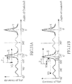
FIG. 1 , a graph illustrating a comparison between crankshaft-angle positions and resistance of start for ISG according to the present invention, the vertical axis coordinate indicates a resistance of start for an ISG forward rotation, while the horizontal axis coordinate indicates angles of crankshaft rotation. According to the present invention, the four-stroke engine operational principle is adopted. Namely, the four strokes are divided from positions of movement of the piston in a cylinder. Therefore, every 180 degree of crankshaft rotation will reach to a top dead center (T.D.C) or a bottom dead center (B.D.C). By starting from zero (0) degree of crankshaft rotation, the intervals are divided into a power stroke, exhaust stroke, intake stroke, and compression stroke, during a cycle of which the crankshaft rotates 720 degree. Under general circumstances, in a compression stroke where a decompression device has not been actuated yet, a curve line drawn with resistance of start relative to angles of crankshaft rotation will be shown as an X curve line. However, in a compression stroke where a centrifugal decompression device is actuated, a curve line drawn with resistance of start relative to angles of crankshaft rotation will be shown as a Y curve line. Further, in a compression stroke where a one-way decompression device functions, a curve line drawn with resistance of start relative to angles of crankshaft rotation will be shown as a Z curve line. There is a smaller resistance at left side and right side of 360 degree due to resistance of an engine valve mechanism. - Further referring to
FIG. 2 a cross-sectional view of an engine according to a first embodiment of the present invention; and toFIG. 3 , a block diagram illustrating the systematic framework of a whole vehicle according to the first embodiment of the present invention, theengine 30 comprises acylinder head 36, acrankshaft 31, apower output shaft 34, atransmission device 35, anISG 23, and a one-way decompression device 32. The ISG is arranged at one end of thecrankshaft 31, whereas thetransmission device 35 is arranged at one end of thepower output shaft 34. - As shown in
FIG. 3 , theISG 23 is arranged in a motorcycle comprising abattery 10, astart button 11, anengine control unit 33, athrottle actuating device 12, and anengine 30. Theengine 30 is equipped with the one-way decompression device 32 for decreasing resistance of thecrankshaft 31 of theengine 30 so as to enhance smoothness of rotation of thecrankshaft 31 and to facilitate a start operation. Namely, theISG 23 is connected with thebattery 10, thestart button 11, thethrottle actuating device 12, theengine control unit 33, and theengine 30. - Now references are made to
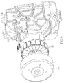
FIG. 4 , a block diagram illustrating a framework including an ISG and a drive controlling device according to the first embodiment of the present invention;FIG. 5 , a plane view illustrating a crankshaft-angle sensor laid out on an engine case according to the first embodiment of the present invention; andFIG. 3 . TheISG 23, adrive controlling device 21, anangle sensing device 22, thebattery 10, theengine control unit 33, and theengine 30 are electrically connected. Thedrive controlling device 21 can detect, through theangle sensing device 22, information including angle phase sequence of theISG 23, angular positions of thecrankshaft 31 of theengine 30, and so forth. In the present embodiment, theangle sensing device 22 includes anISG angle sensor 221 and acrankshaft angle sensor 222. Through the above design, theangle sensing device 22 can detect signals including electrical angles of theISG 23 and angles of thecrankshaft 31 so as to effectively identify piston strokes of theengine 30. - Further, the
ISG 23 includes arotor 231 and astator 232, in connection with thecrankshaft 31 of theengine 30. In order to control the state of operation for theISG 23 and theengine 30, theangle sensing device 22 is arranged on anengine case 301. Referring toFIG. 6 , a perspective view illustrating an ISG-angle sensor laid out on the engine case according to the first embodiment of the present invention, the ISG-angle sensor 221 includes three or fourHall sensors 2211, arranged on theengine case 301, and a controlling circuit for detecting variation of the magnet polarity of therotor 231 such that the control of ISG commutation for driving mode and the generator mode can be determined. Further, thecrankshaft angle sensor 222 includes a pulse-signal sensing element 2221 and a plurality ofprotrusions 2222 correspondingly provided on an external surface of therotor 231, where theprotrusions 2222 are equidistantly provided thereon. Through the pulse-signal sensing element 2221 detecting positions of eachprotrusion 2222 and feeding back pulse signals, an absolute position at every revolution of thecrankshaft 31 can be perceived and such signal can be connected to theengine control unit 33. - References are made to
FIG. 7 , a block diagram illustrating a layout of the drive controlling device and a battery according to the first embodiment of the present invention, andFIG. 3 . A key-power switch S1, a main-power switch S2, and a large-power switch S3 are arranged between thedrive controlling device 21 and thebattery 10, where even under the circumstance that the key-power switch S1 is shut off, thedrive controlling device 21 is still powered by connecting thebattery 10 with the main-power switch S2, which has a function of delayed switch-off, and so does the large-power switch S3. As such, variation in angles and positions of thecrankshaft 31 of theengine 30 can still be detected by theangle sensing device 22, where the angles of thecrankshaft 31 being calculated are used for driving control. - Now referring to
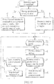
FIG. 8 , a flow chart illustrating a method for controlling engine start according to the first embodiment of the present invention; and toFIG. 9 , a graph illustrating reverse angles of thecrankshaft 31 according to the first embodiment of the present invention, the method for controlling engine start comprises the following steps: - (A) Determining whether a starting signal is received, if Yes, then performing step (B), if No, then returning to step (A);
- (B) At a reverse rotation starting point L1, driving reversely the
crankshaft 31 to a specific range of angles P, and actuating the one-way decompression device 32; - (C) Driving forward rotation of the
crankshaft 31 so as to start theengine 30, and determining whether thecrankshaft 31 rotates at a speed greater than a threshold of engine start rotation speed, if Yes, then performing step (D), if No, then performing step (C1); - (C1) Determining whether the drive exceeds a predetermined time, if Yes, then stopping the drive and returning to step (A), if No, then returning to step (C); and
- (D) Stopping the drive, and the
ISG 23 entering into a generator mode. - Accordingly, as shown in
FIG. 9 , no matter where the reverse rotation starting point L1 is, the one-way decompression device 32 can be triggered for decompression simply by reversely rotating thecrankshaft 31 for the specific range of angles P; thereafter, driving theISG 23 for a forward rotation at a forward rotation drive starting point L2 so as to start theengine 30 successfully. Differences between the reverse rotation starting point L1 and the forward rotation drive starting point L2 fall within the specific range of angles P. - In the first embodiment, the specific range of angles P refers to 40-140 degrees so as to ensure a successful actuating of the one-
way decompression device 32 when theengine 30 starts. Further, the predetermined time for driving thecrankshaft 31 is four (4) seconds so as to determine whether thecrankshaft 31 rotates at a speed greater than the threshold of engine start rotation speed. In case theengine 30 is not started successfully in four (4) seconds, then the drive will be stopped, and returning to step (A). On the other hand, suppose it is greater than the threshold of engine start rotation speed within four (4) seconds, namely theengine 30 starts successfully, then performing step (D) to stop the drive and theISG 23 entering into a generator mode. - Further referring to
FIG. 10 , a flow chart illustrating a method for controlling engine stop according to a second embodiment of the present invention; and toFIG. 11A , a graph illustrating reverse angles of the crankshaft, with spontaneous reverse rotation after the engine stop, according to the second embodiment of the present invention, the second embodiment is similar to the first embodiment as far as the structural framework is concerned, references may be made to the description directed toFIGs. 2 to 7 . In the second embodiment, the method for controlling engine stop comprises: (A) Detecting an angle of thecrankshaft 31 before theengine 30 stops, and determining whether there is an action of spontaneous reverse rotation, if Yes, then performing step (B), if No, then performing step (C). When there is an action of spontaneous reverse rotation, as shown inFIG. 11A , step (B), at a spontaneous reverse rotation starting point M1, controls the action of spontaneous reverse rotation to make thecrankshaft 31 reversely rotate to a specific range of angles P and to actuate the one-way decompression device 32, and after which the control stops. Namely, when theengine 30 stops, no matter whether the key-power switch S1 turns off, theangle sensing device 22, during a engine stop process of theengine 30, will detect variation in angles and positions of thecrankshaft 31 of theengine 30, and use angles of thecrankshaft 31 being calculated to perform a driving control. In other words, even under the circumstance that the key-power switch S1 turns off, thedrive controlling device 21 is still powered by connecting thebattery 10 with the main-power switch S2, which has a function of delayed switch-off, and so does the large-power switch S3. As such, variation in angles and positions of thecrankshaft 31 of theengine 30 can still be detected by theangle sensing device 22, where the angles of thecrankshaft 31 being calculated are used for the driving control. - Further, as shown in
FIG. 11A , suppose thecrankshaft 31 has a spontaneous reverse rotation, then no matter where the spontaneous reverse rotation starting point M1 locates, only reversely rotating the specific range of angles P then actuating the one-way decompression device 32 can be performed. After receiving an engine starting signal, theISG 23 is driven for a forward rotation at a forward rotation drive starting point M2. - Now referring to
FIG. 11B , a graph illustrating angles of crankshaft forward and reverse rotations, without spontaneous reverse rotation after the engine stop, according to the second embodiment of the present invention; and also toFIG. 10 , in the case of step (A), when detecting angles of thecrankshaft 31 prior to stop of theengine 30 and determining no action of spontaneous reverse rotation, as shown inFIG. 11B , then continued with step (C) directly so as to drive thecrankshaft 31 for a forward rotation to an appropriate range of angles Q. Thereafter, thecrankshaft 31 is driven for a reverse rotation to a specific range of angles P so as to actuate the one-way decompression device 32, and after which such control is stopped. Namely, in case there is no spontaneous reverse rotation for thecrankshaft 31, no matter where a forward rotation starting point N1 for thecrankshaft 31 is, it is necessary to drive thecrankshaft 31 for a forward rotation to be within the appropriate range of angles Q, then again at a reverse rotation starting point N2 to reversely rotate thecrankshaft 31 to the specific range of angles P so as to actuate the one-way decompression device 32 to proceed with a decompression. Thereafter, when receiving a starting signal, theISG 23 is driven at a forward rotation drive starting point N3 for a forward rotation. As shown inFIG. 11B , the reverse rotation starting point N2 falls within the appropriate range of angles Q. - Further, in the second embodiment, after the
drive controlling device 21 stops controlling, then continued with step (D) so as to determine whether a starting signal is received, if Yes, then performing step (E), if No, then returning to step (D). In step (E), thecrankshaft 31 is driven for a forward rotation so as to start theengine 30; then continued with step (F) so as to determine whether thecrankshaft 31 rotates at a speed greater than an engine start threshold, if Yes, then performing (G), if No, then performing step (F1). In step (F1), the drive is determined as to whether or not exceeding a predetermined time, if Yes, then stopping the drive and returning to step (D), if No, then returning to step (E). Further, in step (G), the drive is stopped, and theISG 23 enters into a generator mode. - In the second embodiment, the specific range of angles P refers to 40-140 degrees so as to ensure a successful actuating of the one-
way decompression device 32 when theengine 30 starts. Further, the appropriate range of angles Q relates to 600-680 degrees such that thecrankshaft 31 of theengine 30 can be close to a first compression top dead center as much as possible so as to shorten the time required for starting theengine 30. In addition, the predetermined time for driving thecrankshaft 31 is four (4) seconds so as to determine whether thecrankshaft 31 rotates at a speed greater than the threshold of engine start rotation speed. In case theengine 30 is not started successfully in four (4) seconds, then the drive will be stopped, and returning to step (D). On the other hand, suppose it is greater than the threshold of engine start rotation speed within four (4) seconds, namely theengine 30 starts successfully, then performing step (G) to stop the drive and theISG 23 entering into a generator mode. - In the first and second embodiments, whether for the method for controlling engine stop or the method for controlling engine start, the starting signal for the
engine 30 refers to either one of the following: a starting signal transmitted from theengine control unit 33; or a signal indicating pressing of thestart button 11 and a signal indicating actuation of thethrottle actuating device 12. Thethrottle actuating device 12 relates to providing a micro switch on a throttle cable such that when driving the throttle cable, the micro switch will be triggered; or providing a sensor on a throttle grip for detecting whether the throttle grip has been turned such that either the micro switch or the throttle grip sensor may be regarded as thethrottle actuating device 12. - In the first and second embodiments, the
engine control unit 33 can control theengine 30 so as to make it have a function of idle stop. - Further, in the first and second embodiments, in addition to the one-
way decompression device 32, a centrifugal decompression device can be installed as well. As such, during a starting process, theengine 30 can, at the first compression stroke, release most compression pressure through the one-way decompression device 32, so that theengine 30 can start under a minor resistance. The one-way decompression device 32 requires a reverse rotation to the specific range of angles P in order to actuate a decompression function. The one-way decompression device 32 then follows with a stroke of forward rotation, and after which, the decompression function is deactivated. Prior to the engine rotation speed reaching to a specific rotation speed, the centrifugal decompression device actuates a decompression function. Accordingly, the subsequent compression stroke, after the one-way decompression device 32 has deactivated, can release part of the compression pressure so as to lower resistance for theengine 30, however maintaining a compression pressure for a condition of combustion for starting theengine 30. - Given the above, in the first and second embodiments, no matter under the circumstance of engine start with a reverse rotation drive or of engine restart after an engine stop, either type of engine start has its own corresponding measure to start the
engine 30, and incorporates with the one-way decompression device 32 to ensure that theISG 23, during a process of driving theengine 30 for a start, stands in a decompression status at the first compression stroke, and then follows with a forward rotation drive so as to start theengine 30 smoothly. The above-mentioned two controlling measures can make the engine start successfully within a shortest time upon an order for engine start has been given. - Although the present invention has been explained in relation to its preferred embodiments, it is to be understood that many other possible modifications and variations can be made without departing from the scope of the invention as hereinafter claimed.
Claims (10)
- A method for controlling engine start, being used in a motorcycle, wherein the motorcycle is equipped with an engine having a crankshaft and a one-way decompression device, an ISG for driving the engine for a forward rotation or a reverse rotation, an angle sensing device for detecting angles of the crankshaft, and a drive controlling device for controlling the ISG, the drive controlling device being featured in a method for controlling engine start, comprising the following steps:(A) Determining whether a starting signal is received, if Yes, then performing step (B), if No, then returning to step (A);(B) Driving reversely the crankshaft to a specific range of angles, and actuating the one-way decompression device;(C) Driving forward rotation of the crankshaft so as to start the engine, and determining whether the crankshaft rotates at a speed greater than a threshold of engine start rotation speed, if Yes, then performing step (D), if No, then performing step (C1);(C1) Determining whether the drive exceeds a predetermined time, if Yes, then stopping the drive and returning to step (A), if No, then returning to step (C); and(D) Stopping the drive, and the ISG entering into a generator mode.
- A method for controlling engine stop, being used in a motorcycle, wherein the motorcycle is equipped with an engine having a crankshaft and a one-way decompression device, an ISG for driving the engine for a forward rotation or a reverse rotation, an angle sensing device for detecting angles of the crankshaft, and a drive controlling device for controlling the ISG, the drive controlling device being featured in a method for controlling engine stop, comprising the following steps:(A) Detecting an angle of the crankshaft before the engine stops, and determining whether there is an action of spontaneous reverse rotation, if Yes, then performing step (B), if No, then performing step (C);(B) Controlling the action of spontaneous reverse rotation so as to make the crankshaft rotate for a specific range of angles, and after actuating the one-way decompression device, stopping such control; and(C) Driving forward rotation of the crankshaft to an appropriate range of angles, then driving the crankshaft for a reverse rotation to specific range of angles, and after actuating the one-way decompression device, stopping such control.
- The controlling method as claimed in claim 2, wherein the drive controlling device has a function of power delayed switch-off, as such, even after shutting off power of the drive controlling device, the method for controlling engine stop can still be performed.
- The controlling method as claimed in claim 2, wherein the engine has a function of idle stop, as such, upon an engine stop, the method for controlling engine stop can be performed.
- The controlling method as claimed in claim 2, wherein after the drive controlling device has stopped the control, further comprising the following steps:(D) Determining whether a starting signal is received, if Yes, then performing step (E), if No, then returning to step (D);(E) Driving forward rotation of the crankshaft so as to start the engine;(F) Determining whether the crankshaft rotates at a speed greater than a threshold of engine start rotation speed, if Yes, then performing step (G), if No, then performing step (F1);(F1) Determining whether the drive exceeds a predetermined time, if Yes, then stopping the drive and returning to step (D), if No, then returning to step (E); and(G) Stopping the drive, and the ISG entering into a generator mode.
- The controlling method as claimed in claim 1 or 2, wherein the specific range of angles refers to 40-140 degrees.
- The controlling method as claimed in claim 2, wherein the appropriate range of angles relates to 600-680 degrees.
- The controlling method as claimed in claim 1 or 2, wherein the motorcycle is further equipped with a centrifugal decompression device.
- The controlling method as claimed in claim 1 or 2, wherein the motorcycle is further arranged with a start button, a throttle actuating device, and an engine control unit; and wherein the starting signal for the engine refers to either one of the following: a starting signal transmitted from the engine control unit, or a signal indicating pressing of the start button and a signal indicating actuation of the throttle actuating device.
- The controlling method as claimed in claim 1 or 5, wherein the predetermined time is four (4) seconds.
Applications Claiming Priority (1)
| Application Number | Priority Date | Filing Date | Title |
|---|---|---|---|
| TW104124344A TWI560363B (en) | 2015-07-28 | 2015-07-28 | Methods for controlling engines starting and stop running |
Publications (1)
| Publication Number | Publication Date |
|---|---|
| EP3147495A1 true EP3147495A1 (en) | 2017-03-29 |
Family
ID=54979429
Family Applications (1)
| Application Number | Title | Priority Date | Filing Date |
|---|---|---|---|
| EP15200562.5A Withdrawn EP3147495A1 (en) | 2015-07-28 | 2015-12-16 | Method for controlling engine start/stop |
Country Status (2)
| Country | Link |
|---|---|
| EP (1) | EP3147495A1 (en) |
| TW (1) | TWI560363B (en) |
Cited By (5)
| Publication number | Priority date | Publication date | Assignee | Title |
|---|---|---|---|---|
| EP3376018A3 (en) * | 2017-03-15 | 2018-11-07 | Kwang Yang Motor Co., Ltd. | System and method for positioning a crankshaft of an engine of a vehicle |
| EP3533994A1 (en) * | 2018-03-02 | 2019-09-04 | Yamaha Hatsudoki Kabushiki Kaisha | Method for controlling an engine unit for a straddled vehicle, engine unit and straddled vehicle |
| DE102021205880B4 (en) | 2020-06-25 | 2023-02-09 | Prüfrex engineering e motion gmbh & co. kg | Method and device for determining a crankshaft position of an internal combustion engine |
| DE102022210266A1 (en) * | 2022-09-28 | 2024-03-28 | Robert Bosch Gesellschaft mit beschränkter Haftung | Method for starting a combustion engine on two-wheelers |
| JP7635639B2 (en) | 2021-05-26 | 2025-02-26 | スズキ株式会社 | Engine starting device |
Families Citing this family (3)
| Publication number | Priority date | Publication date | Assignee | Title |
|---|---|---|---|---|
| TWI613365B (en) * | 2017-01-11 | 2018-02-01 | 三陽工業股份有限公司 | Method for controlling engines running |
| TWI726673B (en) * | 2020-04-08 | 2021-05-01 | 國立虎尾科技大學 | System of hybrid vehicle and control method thereof |
| TWI852768B (en) * | 2023-09-18 | 2024-08-11 | 瑞洲電裝股份有限公司 | Driving control method and driving system |
Citations (8)
| Publication number | Priority date | Publication date | Assignee | Title |
|---|---|---|---|---|
| EP1055816A1 (en) * | 1998-12-09 | 2000-11-29 | Mitsuba Corporation | Starting device for internal combustion engines and starting control device |
| US20030140881A1 (en) * | 2001-12-05 | 2003-07-31 | Hiroyuki Makajima | Engine starting control apparatus |
| US20040149247A1 (en) * | 2003-02-04 | 2004-08-05 | Toyota Jidosha Kabushiki Kaisha | Stop and start control apparatus of internal combustion engine |
| US20130179054A1 (en) * | 2010-09-10 | 2013-07-11 | Robert Bosch Gmbh | Method and device for controlling an internal combustion engine |
| US20130247871A1 (en) * | 2012-03-21 | 2013-09-26 | Suzuki Motor Corporation | Stop control system for engine |
| EP2719883A1 (en) * | 2012-10-11 | 2014-04-16 | Yamaha Hatsudoki Kabushiki Kaisha | Engine System |
| WO2015093575A1 (en) * | 2013-12-20 | 2015-06-25 | ヤマハ発動機株式会社 | Engine unit and vehicle |
| DE102015009235A1 (en) * | 2014-07-17 | 2016-01-21 | Suzuki Motor Corporation | ENGINE START CONTROL DEVICE |
Family Cites Families (7)
| Publication number | Priority date | Publication date | Assignee | Title |
|---|---|---|---|---|
| ES2392820T3 (en) * | 2002-07-31 | 2012-12-14 | Yamaha Hatsudoki Kabushiki Kaisha | Engine control device |
| JP4082578B2 (en) * | 2002-10-04 | 2008-04-30 | 本田技研工業株式会社 | Engine start control device |
| JP2006070752A (en) * | 2004-08-31 | 2006-03-16 | Nissan Motor Co Ltd | ENGINE START CONTROL DEVICE AND CONTROL METHOD |
| FR2875551B1 (en) * | 2004-09-23 | 2006-11-24 | Valeo Equip Electr Moteur | METHOD FOR CONTROLLING AN AUTOMATIC STARTING / STOP CONTROL OF A VEHICLE |
| TWM271948U (en) * | 2004-12-22 | 2005-08-01 | Kwang Yang Motor Co | Engine decompression device |
| TWI476320B (en) * | 2012-03-21 | 2015-03-11 | Kwang Yang Motor Co | Reduce the engine starting torque control method |
| WO2015104831A1 (en) * | 2014-01-10 | 2015-07-16 | ヤマハ発動機株式会社 | Four-cylinder engine and operating method for four-cylinder engine |
-
2015
- 2015-07-28 TW TW104124344A patent/TWI560363B/en active
- 2015-12-16 EP EP15200562.5A patent/EP3147495A1/en not_active Withdrawn
Patent Citations (8)
| Publication number | Priority date | Publication date | Assignee | Title |
|---|---|---|---|---|
| EP1055816A1 (en) * | 1998-12-09 | 2000-11-29 | Mitsuba Corporation | Starting device for internal combustion engines and starting control device |
| US20030140881A1 (en) * | 2001-12-05 | 2003-07-31 | Hiroyuki Makajima | Engine starting control apparatus |
| US20040149247A1 (en) * | 2003-02-04 | 2004-08-05 | Toyota Jidosha Kabushiki Kaisha | Stop and start control apparatus of internal combustion engine |
| US20130179054A1 (en) * | 2010-09-10 | 2013-07-11 | Robert Bosch Gmbh | Method and device for controlling an internal combustion engine |
| US20130247871A1 (en) * | 2012-03-21 | 2013-09-26 | Suzuki Motor Corporation | Stop control system for engine |
| EP2719883A1 (en) * | 2012-10-11 | 2014-04-16 | Yamaha Hatsudoki Kabushiki Kaisha | Engine System |
| WO2015093575A1 (en) * | 2013-12-20 | 2015-06-25 | ヤマハ発動機株式会社 | Engine unit and vehicle |
| DE102015009235A1 (en) * | 2014-07-17 | 2016-01-21 | Suzuki Motor Corporation | ENGINE START CONTROL DEVICE |
Cited By (5)
| Publication number | Priority date | Publication date | Assignee | Title |
|---|---|---|---|---|
| EP3376018A3 (en) * | 2017-03-15 | 2018-11-07 | Kwang Yang Motor Co., Ltd. | System and method for positioning a crankshaft of an engine of a vehicle |
| EP3533994A1 (en) * | 2018-03-02 | 2019-09-04 | Yamaha Hatsudoki Kabushiki Kaisha | Method for controlling an engine unit for a straddled vehicle, engine unit and straddled vehicle |
| DE102021205880B4 (en) | 2020-06-25 | 2023-02-09 | Prüfrex engineering e motion gmbh & co. kg | Method and device for determining a crankshaft position of an internal combustion engine |
| JP7635639B2 (en) | 2021-05-26 | 2025-02-26 | スズキ株式会社 | Engine starting device |
| DE102022210266A1 (en) * | 2022-09-28 | 2024-03-28 | Robert Bosch Gesellschaft mit beschränkter Haftung | Method for starting a combustion engine on two-wheelers |
Also Published As
| Publication number | Publication date |
|---|---|
| TWI560363B (en) | 2016-12-01 |
| TW201704630A (en) | 2017-02-01 |
Similar Documents
| Publication | Publication Date | Title |
|---|---|---|
| CN1214184C (en) | Engine starting device | |
| TW479106B (en) | Starter, start control device, and crank angle detector of internal combustion engine | |
| TWI605191B (en) | Crankshaft angle control method and system thereof | |
| JPWO2002027182A1 (en) | Engine starter | |
| US9074529B2 (en) | Drive controlling apparatus and drive controlling method | |
| CN102859181B (en) | Drive controller, drive control system, and drive control method | |
| TW201704630A (en) | Methods for controlling engines starting and stop running | |
| JP5929342B2 (en) | Vehicle start control device | |
| CN107076092B (en) | Engine starting gear | |
| CN106401832B (en) | Method for controlling engine starting of starting and power generating device | |
| TWI658202B (en) | Method of starting an internal combustion engine | |
| TW201542927A (en) | A method for controlling engine starting of a starter and generator device | |
| CN106545420B (en) | Engine start and stop control method | |
| JP6869224B2 (en) | The process of managing the restart of an internal combustion engine in a start and stop system | |
| JP6019246B2 (en) | Engine start control device | |
| CN105986949A (en) | Method for controlling engine to start through starting and electricity generating device | |
| TWI613364B (en) | Method for controlling engine starting of a starter and generator device | |
| TWI613363B (en) | A method for controlling engine starting of a starter and generator device | |
| EP3533994B1 (en) | Method for controlling an engine unit for a straddled vehicle, engine unit and straddled vehicle | |
| TWI595155B (en) | Calculation method of crankshaft angle of engine having integrated starter generator | |
| TW201715144A (en) | Method for controlling engines running | |
| TW201833432A (en) | Crankshaft position synchronization controlling method and system for integrated starter generator characterized in that the problem of having different angles determined by two controllers can be avoided | |
| CN106704072A (en) | Method for controlling starting of engine through starting and electricity generating device | |
| CN108667367A (en) | Crankshaft position synchronization control method and system of integrated starter generator | |
| JP2015155687A (en) | Idling stop control device for vehicle |
Legal Events
| Date | Code | Title | Description |
|---|---|---|---|
| PUAI | Public reference made under article 153(3) epc to a published international application that has entered the european phase |
Free format text: ORIGINAL CODE: 0009012 |
|
| STAA | Information on the status of an ep patent application or granted ep patent |
Free format text: STATUS: THE APPLICATION HAS BEEN PUBLISHED |
|
| AK | Designated contracting states |
Kind code of ref document: A1 Designated state(s): AL AT BE BG CH CY CZ DE DK EE ES FI FR GB GR HR HU IE IS IT LI LT LU LV MC MK MT NL NO PL PT RO RS SE SI SK SM TR |
|
| AX | Request for extension of the european patent |
Extension state: BA ME |
|
| STAA | Information on the status of an ep patent application or granted ep patent |
Free format text: STATUS: REQUEST FOR EXAMINATION WAS MADE |
|
| 17P | Request for examination filed |
Effective date: 20170929 |
|
| RBV | Designated contracting states (corrected) |
Designated state(s): AL AT BE BG CH CY CZ DE DK EE ES FI FR GB GR HR HU IE IS IT LI LT LU LV MC MK MT NL NO PL PT RO RS SE SI SK SM TR |
|
| STAA | Information on the status of an ep patent application or granted ep patent |
Free format text: STATUS: EXAMINATION IS IN PROGRESS |
|
| 17Q | First examination report despatched |
Effective date: 20210610 |
|
| STAA | Information on the status of an ep patent application or granted ep patent |
Free format text: STATUS: THE APPLICATION IS DEEMED TO BE WITHDRAWN |
|
| 18D | Application deemed to be withdrawn |
Effective date: 20211021 |