WO2015093575A1 - Engine unit and vehicle - Google Patents
Engine unit and vehicle Download PDFInfo
- Publication number
- WO2015093575A1 WO2015093575A1 PCT/JP2014/083592 JP2014083592W WO2015093575A1 WO 2015093575 A1 WO2015093575 A1 WO 2015093575A1 JP 2014083592 W JP2014083592 W JP 2014083592W WO 2015093575 A1 WO2015093575 A1 WO 2015093575A1
- Authority
- WO
- WIPO (PCT)
- Prior art keywords
- crankshaft
- stroke
- brushless motor
- phase brushless
- control device
- Prior art date
Links
Images


Classifications
-
- F—MECHANICAL ENGINEERING; LIGHTING; HEATING; WEAPONS; BLASTING
- F02—COMBUSTION ENGINES; HOT-GAS OR COMBUSTION-PRODUCT ENGINE PLANTS
- F02N—STARTING OF COMBUSTION ENGINES; STARTING AIDS FOR SUCH ENGINES, NOT OTHERWISE PROVIDED FOR
- F02N11/00—Starting of engines by means of electric motors
- F02N11/08—Circuits or control means specially adapted for starting of engines
-
- F—MECHANICAL ENGINEERING; LIGHTING; HEATING; WEAPONS; BLASTING
- F02—COMBUSTION ENGINES; HOT-GAS OR COMBUSTION-PRODUCT ENGINE PLANTS
- F02N—STARTING OF COMBUSTION ENGINES; STARTING AIDS FOR SUCH ENGINES, NOT OTHERWISE PROVIDED FOR
- F02N11/00—Starting of engines by means of electric motors
- F02N11/04—Starting of engines by means of electric motors the motors being associated with current generators
-
- F—MECHANICAL ENGINEERING; LIGHTING; HEATING; WEAPONS; BLASTING
- F02—COMBUSTION ENGINES; HOT-GAS OR COMBUSTION-PRODUCT ENGINE PLANTS
- F02N—STARTING OF COMBUSTION ENGINES; STARTING AIDS FOR SUCH ENGINES, NOT OTHERWISE PROVIDED FOR
- F02N19/00—Starting aids for combustion engines, not otherwise provided for
- F02N19/005—Aiding engine start by starting from a predetermined position, e.g. pre-positioning or reverse rotation
-
- F—MECHANICAL ENGINEERING; LIGHTING; HEATING; WEAPONS; BLASTING
- F02—COMBUSTION ENGINES; HOT-GAS OR COMBUSTION-PRODUCT ENGINE PLANTS
- F02D—CONTROLLING COMBUSTION ENGINES
- F02D41/00—Electrical control of supply of combustible mixture or its constituents
- F02D41/02—Circuit arrangements for generating control signals
- F02D41/04—Introducing corrections for particular operating conditions
- F02D41/06—Introducing corrections for particular operating conditions for engine starting or warming up
- F02D41/062—Introducing corrections for particular operating conditions for engine starting or warming up for starting
-
- F—MECHANICAL ENGINEERING; LIGHTING; HEATING; WEAPONS; BLASTING
- F02—COMBUSTION ENGINES; HOT-GAS OR COMBUSTION-PRODUCT ENGINE PLANTS
- F02N—STARTING OF COMBUSTION ENGINES; STARTING AIDS FOR SUCH ENGINES, NOT OTHERWISE PROVIDED FOR
- F02N19/00—Starting aids for combustion engines, not otherwise provided for
- F02N19/004—Aiding engine start by using decompression means or variable valve actuation
-
- F—MECHANICAL ENGINEERING; LIGHTING; HEATING; WEAPONS; BLASTING
- F02—COMBUSTION ENGINES; HOT-GAS OR COMBUSTION-PRODUCT ENGINE PLANTS
- F02N—STARTING OF COMBUSTION ENGINES; STARTING AIDS FOR SUCH ENGINES, NOT OTHERWISE PROVIDED FOR
- F02N11/00—Starting of engines by means of electric motors
- F02N11/08—Circuits or control means specially adapted for starting of engines
- F02N2011/0881—Components of the circuit not provided for by previous groups
- F02N2011/0896—Inverters for electric machines, e.g. starter-generators
-
- F—MECHANICAL ENGINEERING; LIGHTING; HEATING; WEAPONS; BLASTING
- F02—COMBUSTION ENGINES; HOT-GAS OR COMBUSTION-PRODUCT ENGINE PLANTS
- F02N—STARTING OF COMBUSTION ENGINES; STARTING AIDS FOR SUCH ENGINES, NOT OTHERWISE PROVIDED FOR
- F02N2250/00—Problems related to engine starting or engine's starting apparatus
- F02N2250/04—Reverse rotation of the engine
Definitions
- the present invention relates to an engine unit including a four-stroke engine body having a high load region and a low load region during four strokes, and a vehicle equipped with the engine unit.
- a four-stroke engine for example, a single-cylinder engine having a high load region where a load for rotating the crankshaft of the engine is large and a low load region where a load for rotating the crankshaft is small during four strokes.
- Such a 4-stroke engine requires a large output torque from the starter motor in order to rotate the crankshaft beyond the high load region when the engine is started.
- the starter motor is increased in size, and the mountability of the engine unit on the vehicle is reduced. It is desired for the engine unit to improve mountability on a vehicle.
- Patent Document 1 discloses an engine starter that starts an engine by rotating the crankshaft in the reverse direction and then rotating the crankshaft forward.
- An engine started by an engine starter as shown in Patent Document 1 stops combustion when there is a combustion stop instruction during operation. After the combustion is stopped, the crankshaft rotates 4 to 8 by inertia, and when it cannot pass over the load peak due to the compression reaction force in the compression stroke, the crankshaft rotates in the reverse direction due to the compression reaction force and stops.
- the engine starter disclosed in Patent Document 1 stops the crankshaft by rotating it reversely to a position where the load increases, that is, the expansion stroke after the rotation of the crankshaft has stopped. Thereafter, the engine starter powers the motor in the normal rotation direction to rotate the crankshaft in the normal direction.
- the engine starter reversely rotates the crankshaft until the expansion stroke, the crankshaft rotates normally over almost the entire low load area from the expansion stroke to the compression stroke, and then reaches the first high load area. To do. Therefore, the engine starter can increase the rotation speed of the crankshaft before reaching the first high load region.
- the first high load region can be overcome by using both the large inertial force accompanying the high rotational speed and the output torque of the starter motor.
- the starter motor can be reduced in size by suppressing the output torque of the motor, the mountability of the engine starter on the vehicle can be improved.
- the first start of the high load region is overcome by using both the large inertial force accompanying the high rotational speed and the output torque of the motor. It is intended to improve the mountability on vehicles.
- the engine starting device of Patent Document 1 rotates the crankshaft in the reverse direction until the expansion stroke after the combustion of the engine stops and the rotation due to the inertia of the crankshaft stops. Thereafter, the engine starter starts the engine. For this reason, the engine starting device of Patent Document 1 has a problem that it takes a long time to restart after a combustion stop instruction is given.
- An engine unit including a four-stroke engine body having a high load region and a low load region during the four strokes can achieve both reduction in time until restart after combustion stop instruction and mounting on a vehicle. Is desired.
- An object of the present invention is to provide a four-stroke engine main body having a high load region and a low load region between four strokes, and to achieve both reduction in time until restart after combustion stop instruction and mounting on a vehicle. It is to provide an engine unit that can be operated and a vehicle equipped with the engine unit.
- the present invention employs the following configuration in order to solve the above-described problems.
- An engine unit mounted on a vehicle The engine unit is A four-stroke engine main body having a high load region in which a load for rotating the crankshaft is large during four strokes, and a low load region in which the load for rotating the crankshaft is smaller than the load in the high load region;
- a three-phase brushless motor that is driven by a battery included in the vehicle and starts the four-stroke engine body by rotating the crankshaft in accordance with an input of a start instruction;
- An inverter including a plurality of switching units for controlling a voltage applied from the battery to the three-phase brushless motor;
- a starter motor control unit that controls a voltage applied from the battery to the three-phase brushless motor by controlling the plurality of switching units provided in the inverter, and a combustion operation of the four-stroke engine main body.
- a control device including a combustion control unit, The control device stops the combustion operation of the 4-stroke engine body and the forward rotation of the crankshaft after the combustion operation of the 4-stroke engine body and the forward rotation of the crankshaft are stopped, and the start instruction
- the voltage applied from the battery to the three-phase brushless motor is controlled by controlling the plurality of switching units of the inverter, and the crankshaft is moved from the stop position to the four strokes.
- the start instruction is input after the forward rotation of the crankshaft by the control of the voltage applied to the three-phase brushless motor is stopped in the compression stroke, it is applied from the battery to the three-phase brushless motor.
- the crankshaft is rotated forward from the position of the crankshaft at the time when the start instruction is input.
- the control device controls the plurality of switching units of the inverter to change from the battery to the three-phase brushless motor.
- the crankshaft is rotated forward until the compression stroke in the four strokes including the high load region and the low load region, and is stopped in the compression stroke.
- the control device applies the start instruction from the battery to the three-phase brushless motor after the forward rotation of the crankshaft by the control of the voltage applied to the three-phase brushless motor is stopped in the compression stroke.
- the crankshaft is rotated forward from the position of the crankshaft at the time when the start instruction is input.
- crankshaft starts to rotate forward from the compression stroke. Therefore, the forward rotation of the crankshaft can be started from a position where the four-stroke engine body can be easily started even if the output torque of the motor is small. That is, when the crankshaft starts to rotate in response to the input of the start instruction, the crankshaft gradually increases in speed from the stopped state.
- the crankshaft passes through the compression stroke at a low speed. Since the crankshaft passes through the compression stroke at a low speed, the crankshaft is not easily affected by the compression reaction force of the gas in the combustion chamber. As a result, the crankshaft can quickly get over the load in the high load region of the compression stroke.
- the crankshaft After passing through the compression stroke, the crankshaft rotates forward over a wide low load region from the expansion stroke to the compression stroke, and reaches the second high load region. That is, a long run section for acceleration is secured. Therefore, the three-phase brushless motor can increase the rotational speed of the crankshaft before reaching the second high load region. And the high load area of the 2nd time can be overcome using both the large inertial force accompanying the high rotational speed and the output torque of the three-phase brushless motor. Therefore, it is easy to start the 4-stroke engine body even if the output torque of the motor is small. Therefore, the three-phase brushless motor can be reduced in size while suppressing the output torque of the motor.
- the crankshaft After the combustion operation of the 4-stroke engine body stops, the forward rotation of the crankshaft tends to stop near the compression stroke or the compression stroke.
- the voltage applied from the battery to the three-phase brushless motor is controlled by controlling a plurality of switching units of the inverter after the combustion operation of the four-stroke engine body and the forward rotation of the crankshaft are stopped. And the crankshaft is rotated forward until the compression stroke in the four strokes including the high load region and the low load region. Therefore, according to the engine unit of (1), the crankshaft can be moved to a position where the four-stroke engine body can be easily started with a small output torque in a short time compared with the case where the crankshaft is reversely rotated to the expansion stroke. Can do.
- a plurality of switching units of the inverter are controlled to be applied from the battery to the three-phase brushless motor.
- the crankshaft is rotated forward until the compression stroke in the four strokes including the high load region and the low load region.
- the crankshaft is rotated forward by controlling the voltage applied to the three-phase brushless motor, for example, the crankshaft is moved to the target position as compared with the case of forward rotation by the inertia force of the combustion operation of the 4-stroke engine body. Easy to control.
- crankshaft can be moved in a short time to a position where the 4-stroke engine body can be easily started with a small output torque. Therefore, according to the engine unit of (1), a four-stroke engine main body having a high load region and a low load region is provided during four strokes, and after the combustion stop instruction, the time until restart is reduced and the vehicle is moved. Can be made compatible.
- the engine unit of (1) The four-stroke engine body includes a combustion chamber, and a decompression device that releases pressure in the combustion chamber in the compression stroke,
- the decompression device operates in at least a part of a period in which the control device controls a voltage applied from the battery to the three-phase brushless motor to rotate the crankshaft forward.
- the decompression device operates in at least a part of a period in which the control device controls the voltage applied from the battery to the three-phase brushless motor to rotate the crankshaft forward. Since the decompression device releases the pressure in the combustion chamber during the compression stroke, the load for rotating the crankshaft is reduced. For this reason, even if the output torque of the three-phase brushless motor is smaller, it is possible to quickly get over the load in the high load region. Therefore, according to the engine unit of (2), a 4-stroke engine main body having a high load region and a low load region is provided for 4 strokes, and after the combustion stop instruction, the time until restart is reduced and the vehicle is It is possible to achieve both of the above mountability.
- the engine unit according to (1) or (2) The three-phase brushless motor includes a plurality of teeth arranged in a circumferential direction and a stator having a winding wound around each of the plurality of teeth, and is arranged to face the stator and rotates in conjunction with the crankshaft. And the rotor has a pole face that is greater than 2/3 of the number of the plurality of tooth portions,
- the control device controls the plurality of switching units of the inverter to control the voltage applied from the battery to each of the plurality of windings of the three-phase brushless motor, thereby correcting the crankshaft. Rotate.
- the control device controls the voltage applied from the battery to the windings of the three-phase brushless motor by controlling a plurality of switching units of the inverter, and rotates the crankshaft in the forward direction.
- the number of magnetic pole faces of the rotor of the three-phase brushless motor is larger than 2/3 of the number of teeth.
- the frequency of change in voltage applied to each of the windings of the three-phase brushless motor is high when the control device controls the switching unit. For example, when a pulse waveform voltage is applied to each of the windings of a three-phase brushless motor, the pulse frequency is high.
- the frequency of the voltage applied to each of the windings is high, the frequency of the pulsation of torque applied when the three-phase brushless motor rotates the crankshaft forward is high.
- the crankshaft can easily get over the load in the high load region. Therefore, according to the engine unit (3), a four-stroke engine main body having a high load region and a low load region is provided for four strokes, and after the combustion stop instruction, the time until restart is reduced and the vehicle is moved. It is possible to achieve both of the above mountability.
- the control device controls the plurality of switching units of the inverter to control the three-phase brushless motor at least partly until the end of the compression stroke, so that the torque smaller than the maximum torque obtained by the battery is reduced. Rotate forward with.
- the torque of the three-phase brushless motor is suppressed, so that the speed of forward rotation of the crankshaft is reduced. For this reason, the compression reaction force of the gas in the combustion chamber of the 4-stroke engine main body accompanying the forward rotation of the crankshaft is suppressed. Since the resistance due to the compression reaction force against the rotation of the crankshaft is suppressed, the crankshaft can be moved in a shorter time. Therefore, according to the configuration of (4), it is possible to further shorten the time until restart after the combustion stop instruction.
- a 4-stroke engine main body having a high load region and a low load region is provided for 4 strokes, and after the combustion stop instruction, the time until restart is reduced and the vehicle is moved. Can be combined at a higher level.
- the engine unit controls a voltage applied from the battery to the three-phase brushless motor by controlling the plurality of switching units of the inverter at least partly until the end of the compression stroke, based on the voltage of the battery. Lower the crankshaft and rotate it forward.
- the voltage applied to the three-phase brushless motor is made lower than the voltage of the battery.
- the torque of the three-phase brushless motor is suppressed, and the speed of forward rotation of the crankshaft is reduced.
- the compression reaction force of the gas in the combustion chamber of the 4-stroke engine main body accompanying the forward rotation of the crankshaft is suppressed. Since the resistance due to the compression reaction force to the rotation of the crankshaft is suppressed, the crankshaft can be moved in a shorter time. Therefore, according to the configuration of (5), it is possible to further shorten the time until restart after the combustion stop instruction.
- a 4-stroke engine main body having a high load area and a low load area is provided for 4 strokes, and after the combustion stop instruction, the time until restart is reduced and the vehicle is Can be combined at a higher level.
- the engine unit controls the plurality of switching units of the inverter while the combustion operation of the four-stroke engine main body and the forward rotation of the crankshaft are stopped and the start instruction is not input. If the start instruction is input during the normal rotation of the crankshaft to the compression stroke by controlling the voltage applied to the three-phase brushless motor, the forward rotation of the crankshaft is not stopped in the compression stroke.
- the 4-stroke engine main body is started by continuing the compression stroke beyond the compression stroke.
- the inertial force of the crankshaft that is rotating forward until the compression stroke without input of the start instruction is used for rotation of the crankshaft for restarting the engine body. Time to restart is further reduced.
- the engine unit according to any one of (1) to (5), The control device reversely rotates forward and reverse the crankshaft in a state where the start instruction is not input in accordance with a position where the forward rotation of the crankshaft that has continued from when the combustion operation of the 4-stroke engine main body is stopped. Is switched.
- crankshaft If the crankshaft is rotated in the reverse direction without input of a start instruction, the crankshaft may be moved to a position where the 4-stroke engine body can be easily started in a shorter time than in the case of normal rotation.
- the forward rotation and the reverse rotation of the crankshaft in the state where the start instruction is not input are switched according to the position where the forward rotation of the crankshaft that has continued since the stop of the combustion operation is stopped. Therefore, it is possible to achieve both a shortening of the time until restart after the combustion stop instruction and the mountability on the vehicle at a higher level.
- the second range is closer to the compression top dead center than the first range in the reverse rotation direction.
- the crankshaft when the position where the forward rotation of the crankshaft that has continued from the stop of the combustion operation of the four-stroke engine main body is within the second range, the crankshaft is reversed without input of a start instruction. Rotate. By reverse rotation, the crankshaft can be moved to a position where the four-stroke engine body can be easily started earlier than in the case of normal rotation. Therefore, it is possible to achieve both a shortening of the time until restart after the combustion stop instruction and the mountability on the vehicle at a higher level.
- the controller is By controlling the plurality of switching units of the inverter for a predetermined period after starting the combustion operation of the four-stroke engine body by rotating the crankshaft in accordance with the input of the start instruction.
- the voltage applied to the three-phase brushless motor from the battery is controlled to accelerate the forward rotation of the crankshaft.
- the three-phase brushless motor functions as a generator that generates current for charging the battery by rotating in conjunction with the rotation of the crankshaft after the four-stroke engine body is started.
- the three-phase brushless motor functions as a generator to charge the battery.
- the stator windings of a three-phase brushless motor that also functions as a generator are subject to structural constraints for charging the battery. For example, in order to suppress an excessive charging current, the performance as a three-phase brushless motor is limited.
- the three-phase brushless motor reaches the maximum load position at a low rotational speed due to the suppressed output torque, and accelerates in a sufficient section to the second maximum load position. Even when is restricted, the load at the second maximum load position can be carried over. Therefore, the structure can be simplified by combining the three-phase brushless motor and the generator, and the time until the engine can be restarted after being instructed to stop the combustion can be reduced at a higher level. .
- a vehicle The vehicle is (1) The engine unit of any one of (11) is provided.
- the vehicle of (12) can achieve both reduction of the time until restart after the combustion stop instruction and mounting of the engine unit.
- a four-stroke engine main body having a high load region and a low load region is provided between four strokes, and both a reduction in time until restart after a combustion stop instruction and mounting on a vehicle are achieved. It is possible to provide an engine unit that can be operated and a vehicle equipped with the engine unit.
- FIG. 1 It is a fragmentary sectional view showing typically the schematic structure of the engine unit concerning one embodiment of the present invention. It is explanatory drawing which shows typically the relationship between the crank angle position at the time of engine starting, and required torque. It is the expanded sectional view which expanded and showed the three-phase brushless motor in FIG. 1, and its vicinity part. It is sectional drawing which shows a cross section perpendicular
- movement of the engine unit shown in FIG. (A) is a figure explaining the movement of the crankshaft in the engine unit shown in FIG.
- (b) is a figure explaining the movement of the crankshaft in the case of reverse rotation as a comparative example. It is explanatory drawing which shows typically the relationship between a crank angle position and required torque. It is explanatory drawing which shows typically the relationship between the crank angle position and required torque in the engine unit of 2nd embodiment of this invention. It is a flowchart explaining operation
- Patent Document 1 it takes time to reversely rotate the crankshaft while the combustion operation of the 4-stroke engine main body and the forward rotation of the crankshaft are stopped and no start instruction is input. Therefore, it takes a long time to restart after an instruction to stop combustion.
- the time required for starting the crankshaft is shortened. It is not easy to stop at the target area. This is because, after the combustion operation is stopped, the crankshaft whose rotation is assisted by the motor rotates while having the inertial force due to the last combustion operation in addition to the motor force. It is not easy to position the crankshaft that is rotating while having the inertial force due to the final combustion operation in the target region while assisting the rotation of the crankshaft by the motor.
- the crankshaft rotating while having the inertial force due to the final combustion operation is stopped by using, for example, a high load due to a compression reaction force.
- the crankshaft once reversely rotates without overloading the load and then stops. Since the stop position of the crankshaft depends on the degree (distance) of reverse rotation without getting over the load peak, the crankshaft stop position varies greatly. That is, there is a large variation in the position where rotation starts in response to the input of the start instruction. Therefore, there are many variations in time from when the combustion stop instruction is given until the engine is restarted. Therefore, there are cases where the time until restarting is long.
- FIG. 1 is a partial cross-sectional view schematically showing a schematic configuration of an engine unit EU according to the first embodiment of the present invention.
- the engine unit EU in the present embodiment is a vehicle four-stroke engine unit.
- the engine unit EU is provided in a motorcycle (see FIG. 14) which is an example of a vehicle.
- the engine unit EU includes a four-stroke engine body E and a three-phase brushless motor SG.
- the 4-stroke engine body E is a single-cylinder 4-stroke engine.
- the 4-stroke engine body E has a relationship between the crank angle position and the required torque shown in FIG.
- FIG. 2 is an explanatory diagram schematically showing the relationship between the crank angle position at the time of engine start and the required torque.
- the 4-stroke engine body E has a high load region TH in which the load for rotating the crankshaft 5 is large and a low load region TL in which the load for rotating the crankshaft 5 is smaller than the load in the high load region TH during the four strokes.
- the low load region TL is wider than the high load region TH. More specifically, the low load region TL is wider than the high load region TH. In other words, the rotation angle region corresponding to the low load region TL is wider than the rotation angle region corresponding to the high load region TH.
- the four-stroke engine body E rotates while repeating four steps of an intake stroke, a compression stroke, an expansion stroke, and an exhaust stroke.
- the compression stroke is included in the high load region TH and is not included in the low load region TL.
- the high load region TH is a region that substantially overlaps the compression stroke
- the low load region TL is a region that substantially overlaps the intake stroke, the expansion stroke, and the exhaust stroke.
- each boundary between the high load region TH and the low load region TL does not need to coincide with the boundary of each stroke.
- the engine unit EU includes a three-phase brushless motor SG.
- the three-phase brushless motor SG is a starter motor.
- the three-phase brushless motor SG starts the four-stroke engine body E by rotating the crankshaft 5 forward when the engine is started. Further, the three-phase brushless motor SG is rotated forward by the crankshaft 5 and functions as a generator at least during a period after the start of the four-stroke engine body E. That is, when the three-phase brushless motor SG functions as a generator, the three-phase brushless motor SG does not always need to function as a generator after the start of engine combustion.
- the three-phase brushless motor SG may not function as a generator immediately, and the three-phase brushless motor SG may function as a generator when a predetermined condition is satisfied.
- predetermined conditions include that the engine rotation speed has reached a predetermined speed, and that a predetermined time has elapsed since the start of engine combustion.
- a period during which the three-phase brushless motor SG functions as a generator and a period during which the three-phase brushless motor SG functions as a motor (for example, a vehicle driving motor) may be included.
- the three-phase brushless motor SG is attached to the crankshaft 5 of the 4-stroke engine body E.
- the three-phase brushless motor SG is attached to the crankshaft 5 without a power transmission mechanism (for example, a belt, a chain, a gear, a speed reducer, a speed increaser, etc.).
- the three-phase brushless motor SG only needs to be configured to rotate the crankshaft 5 in the forward direction by the forward rotation of the three-phase brushless motor SG. Therefore, the three-phase brushless motor SG may be attached to the crankshaft 5 via the power transmission mechanism.
- the rotation axis of the three-phase brushless motor SG and the rotation axis of the crankshaft 5 substantially coincide.
- the three-phase brushless motor SG is attached to the crankshaft 5 without using a power transmission mechanism as in the present embodiment.
- the 4-stroke engine body E includes a crankcase 1 (engine case 1), a cylinder 2, a piston 3, a connecting rod 4, and a crankshaft 5.
- the cylinder 2 is provided in a manner protruding from the crankcase 1 in a predetermined direction (for example, obliquely upward).
- the piston 3 is provided in the cylinder 2 so as to be reciprocally movable.
- the crankshaft 5 is rotatably provided in the crankcase 1.
- One end (for example, the upper end) of the connecting rod 4 is connected to the piston 3.
- the other end (for example, the lower end) of the connecting rod 4 is connected to the crankshaft 5.
- a cylinder head 6 is attached to an end portion (for example, an upper end portion) of the cylinder 2.
- crankshaft 5 is supported on the crankcase 1 through a pair of bearings 7 in a rotatable manner.
- One end portion 5 a (for example, right end portion) of the crankshaft 5 protrudes outward from the crankcase 1.
- a three-phase brushless motor SG is attached to one end portion 5 a of the crankshaft 5.
- the other end 5b (for example, the left end) of the crankshaft 5 protrudes outward from the crankcase 1.
- a primary pulley 20 of a continuously variable transmission CVT is attached to the other end portion 5 b of the crankshaft 5.
- the primary pulley 20 has a fixed sheave 21 and a movable sheave 22.
- the fixed sheave 21 is fixed to the distal end portion of the other end portion 5 b of the crankshaft 5 so as to rotate together with the crankshaft 5.
- the movable sheave 22 is splined to the other end 5 b of the crankshaft 5.
- the movable sheave 22 is movable along the axial direction X, and rotates with the crankshaft 5 in such a manner that the distance from the fixed sheave 21 is changed.
- a belt B is hung on the primary pulley 20 and a secondary pulley (not shown). The rotational force of the crankshaft 5 is transmitted to the drive wheels of the motorcycle (see FIG. 8).
- FIG. 3 is an enlarged cross-sectional view showing the three-phase brushless motor SG in FIG. 1 and the vicinity thereof in an enlarged manner.
- 4 is a cross-sectional view showing a cross section perpendicular to the rotation axis J of the three-phase brushless motor SG shown in FIG.
- the three-phase brushless motor SG has an outer rotor 30 and an inner stator 40.
- the outer rotor 30 has an outer rotor main body 31.
- the outer rotor main body 31 is made of, for example, a ferromagnetic material.
- the outer rotor main body 31 has a bottomed cylindrical shape.
- the outer rotor main body 31 includes a cylindrical boss portion 32, a disk-shaped bottom wall portion 33, and a cylindrical back yoke portion 34.
- the cylindrical boss portion 32 is fixed to the crankshaft 5 while being inserted into the one end portion 5 a of the crankshaft 5.
- the bottom wall portion 33 is fixed to the cylindrical boss portion 32 and has a disk shape that extends in the radial direction Y of the crankshaft 5.
- the back yoke portion 34 has a cylindrical shape that extends in the axial direction X of the crankshaft 5 from the outer peripheral edge of the bottom wall portion 33. The back yoke portion 34 extends in a direction
- the bottom wall portion 33 and the back yoke portion 34 are integrally formed, for example, by press molding a metal plate.
- the bottom wall portion 33 and the back yoke portion 34 may be configured separately. That is, in the outer rotor main body 31, the back yoke portion 34 may be formed integrally with other parts constituting the outer rotor main body 31, and is separate from other parts constituting the outer rotor main body 31. It may be configured on the body. In the case where the back yoke portion 34 and other portions are configured separately, the back yoke portion 34 may be made of a ferromagnetic material, and the other portion may be made of a material other than the ferromagnetic material. .
- a tapered insertion hole 32 a for inserting one end portion 5 a of the crankshaft 5 is formed along the axial direction X of the crankshaft 5.
- the tapered insertion hole 32 a has a taper angle corresponding to the outer peripheral surface of the one end portion 5 a of the crankshaft 5.
- the cylindrical boss portion 32 has a large-diameter portion 32b at the proximal end portion of the cylindrical boss portion 32 (the right portion of the cylindrical boss portion 32 in the drawing).
- the cylindrical boss portion 32 has a flange portion 32c extending outward in the radial direction on the outer peripheral surface of the large diameter portion 32b.
- a large-diameter portion 32b of the cylindrical boss portion 32 is inserted into a hole portion 33a formed in the center portion of the bottom wall portion 33 of the outer rotor main body portion 31. In this state, the flange portion 32c is in contact with the outer peripheral surface (right side surface in the figure) of the bottom wall portion 33.
- the three-phase brushless motor SG is a permanent magnet motor.
- the back yoke portion 34 of the outer rotor main body 31 is provided with a plurality of permanent magnet portions 37 on the inner peripheral surface of the back yoke portion 34.
- Each permanent magnet portion 37 is provided such that the S pole and the N pole are aligned in the radial direction of the three-phase brushless motor SG.
- the plurality of permanent magnet portions 37 are provided so that N poles and S poles are alternately arranged in the circumferential direction of the three-phase brushless motor SG.
- the number of magnetic poles of the outer rotor 30 facing the inner stator 40 is 24.
- the number of magnetic poles of the outer rotor 30 refers to the number of magnetic poles facing the inner stator 40.
- the number of magnetic pole surfaces of the permanent magnet portion 37 facing the tooth portion 43 of the stator core ST corresponds to the number of magnetic poles of the outer rotor 30.
- the magnetic pole surface per magnetic pole included in the outer rotor 30 corresponds to the magnetic pole surface of the permanent magnet portion 37 facing the inner stator 40.
- the magnetic pole surface of the permanent magnet part 37 is covered with a nonmagnetic material (not shown) provided between the permanent magnet part 37 and the inner stator 40. No magnetic material is provided between the permanent magnet portion 37 and the inner stator 40. It does not specifically limit as a nonmagnetic material, For example, a stainless steel material is mentioned.
- the permanent magnet portion 37 is a ferrite magnet.
- conventionally known magnets such as neodymium bond magnets, samarium cobalt magnets and neodymium magnets can be employed as the permanent magnets.
- the shape of the permanent magnet part 37 is not particularly limited.
- the outer rotor 30 may be an embedded magnet type (IPM type) in which the permanent magnet part 37 is embedded in a magnetic material, but the permanent magnet part 37 is exposed from the magnetic material as in the present embodiment.
- a surface magnet type (SPM type) is preferred.
- the outer rotor 30 attached to the crankshaft 5 and attached to rotate together with the crankshaft 5 is a rotating body for increasing the inertia of the crankshaft 5.
- a cooling fan F having a plurality of blade portions Fa is provided on the outer peripheral surface (the right side surface in FIGS. 1 and 3) of the bottom wall portion 33 constituting the outer rotor 30.
- the cooling fan F is fixed to the outer peripheral surface of the bottom wall portion 33 with a fixture (a plurality of bolts Fb).
- the inner stator 40 has a stator core ST and a plurality of stator windings W.
- the stator core ST is formed, for example, by laminating thin silicon steel plates along the axial direction.
- the stator core ST has a hole 41 having an inner diameter larger than the outer diameter of the cylindrical boss portion 32 of the outer rotor 30 at the center of the stator core ST.
- the stator core ST has a plurality of tooth portions 43 that integrally extend outward in the radial direction (see FIG. 4).
- a total of 18 tooth portions 43 are provided at intervals in the circumferential direction.
- the stator core ST has a total of 18 slots SL (see FIG. 4) formed at intervals in the circumferential direction.
- the tooth portions 43 are arranged at substantially equal intervals in the circumferential direction.
- a stator winding W is wound around each tooth portion 43.
- the multi-phase stator winding W is provided so as to pass through the slot SL.
- Each of the multi-phase stator windings W belongs to one of the U phase, the V phase, and the W phase.
- the stator windings W are arranged in the order of the U phase, the V phase, and the W phase.
- the stator winding W corresponds to an example of a winding referred to in the present invention.
- the inner stator 40 corresponds to an example of a stator according to the present invention.
- the outer rotor 30 corresponds to an example of a rotor according to the present invention.
- the inner stator 40 is formed with a hole 41 in the central portion in the radial direction of the three-phase brushless motor SG.
- the crankshaft 5 and the cylindrical boss portion 32 of the outer rotor 30 are disposed at a distance from the wall surface (inner stator 40) of the hole portion 41.
- the inner stator 40 is attached to the crankcase 1 of the four-stroke engine main body E.
- the end portion (tip surface) of the tooth portion 43 of the inner stator 40 is disposed at a distance from the magnetic pole surface (inner peripheral surface) of the permanent magnet portion 37 constituting the outer rotor 30.
- the outer rotor 30 rotates in conjunction with the rotation of the crankshaft 5.
- the outer rotor 30 rotates integrally with the crankshaft 5. In other words, the rotational speed of the outer rotor 30 is the same as the rotational speed of the crankshaft 5.
- the outer rotor 30 will be further described with reference to FIG.
- the permanent magnet portion 37 is provided outside the inner stator 40 in the radial direction of the three-phase brushless motor SG.
- the back yoke portion 34 is provided outside the permanent magnet portion 37 in the radial direction.
- the permanent magnet portion 37 includes a plurality of magnetic pole surfaces 37 a on the surface facing the inner stator 40.
- the magnetic pole surface 37a is arranged in the circumferential direction of the three-phase brushless motor SG.
- Each of the magnetic pole surfaces 37a is an N pole or an S pole.
- the N pole and the S pole are alternately arranged in the circumferential direction of the three-phase brushless motor SG.
- the magnetic pole surface 37 a of the permanent magnet portion 37 faces the inner stator 40.
- a plurality of magnets are arranged in the circumferential direction of the three-phase brushless motor SG, and each of the plurality of magnets has a posture in which the S pole and the N pole are aligned in the radial direction of the three-phase brushless motor SG.
- a pair of magnetic pole faces 37p is constituted by one S pole and one N pole adjacent in the circumferential direction.
- the number of pairs of magnetic pole faces 37p is 1 ⁇ 2 of the number of magnetic pole faces 37a.
- the outer rotor 30 is provided with 24 magnetic pole surfaces 37a facing the inner stator 40, and the number of pairs 37p of the magnetic pole surfaces of the outer rotor 30 is twelve.
- the three-phase brushless motor SG has more magnetic pole surfaces 37 a than 2/3 of the number of tooth portions 43.
- the three-phase brushless motor SG has the number of magnetic pole surfaces 37 a that is 4/3 or more of the number of tooth portions 43.
- a plurality of detected portions 38 for detecting the rotational position of the outer rotor 30 are provided on the outer surface of the outer rotor 30.
- the plurality of detected parts 38 are detected by a magnetic action.
- the plurality of detected portions 38 are provided on the outer surface of the outer rotor 30 at intervals in the circumferential direction.
- the plurality of detected portions 38 are provided on the outer peripheral surface of the outer rotor 30 at intervals in the circumferential direction.
- the plurality of detected portions 38 are disposed on the outer peripheral surface of the cylindrical back yoke portion 34.
- Each of the plurality of detected portions 38 protrudes outward in the radial direction Y of the three-phase brushless motor SG from the outer peripheral surface of the back yoke portion 34.
- the bottom wall portion 33, the back yoke portion 34, and the detected portion 38 are integrally formed, for example, by press-molding a metal plate such as iron. That is, the detected part 38 is made of a ferromagnetic material. Details of the arrangement of the detected parts 38 will be described later.
- the rotor position detection device 50 is a device that detects the position of the outer rotor 30.
- the rotor position detection device 50 is provided at a position facing the plurality of detected parts 38. That is, the rotor position detection device 50 is disposed at a position where the plurality of detected portions 38 sequentially face the rotor position detection device 50.
- the rotor position detection device 50 faces a path through which the detected portion 38 passes as the outer rotor 30 rotates.
- the rotor position detection device 50 is disposed at a position away from the inner stator 40.
- the rotor position detection device 50 includes the back yoke portion 34 and the permanent magnet portion 37 of the outer rotor 30 between the rotor position detection device 50 and the inner stator 40 and the stator winding W in the radial direction of the crankshaft 5. Is arranged to be located.
- the rotor position detection device 50 is disposed outside the outer rotor 30 in the radial direction of the three-phase brushless motor SG, and faces the outer peripheral surface of the outer rotor 30.
- the rotor position detection device 50 includes a detection winding 51, a detection magnet 52, and a core 53.
- the detection winding 51 functions as a pickup coil that detects the detected portion 38.
- the core 53 is a member extending in the shape of, for example, an iron bar.
- the detection winding 51 magnetically detects the detected portion 38.
- the rotor position detection device 50 starts detecting the rotational position of the outer rotor 30 after the crankshaft 5 starts rotating.
- the rotor position detecting device 50 may employ a configuration other than the type in which the voltage generated by the electromotive force associated with the passage of the detected portion 38 changes.
- the rotor position detection device 50 may employ a configuration in which the detection winding 51 is always energized and the energization current changes due to the change in inductance accompanying the passage of the detected portion 38.
- the rotor position detection device 50 is not particularly limited, and may include a Hall element or an MR element.
- the engine unit EU (see FIG. 1) of the present embodiment may include a Hall element or an MR element.
- the plurality of detected portions 38 in the present embodiment are provided on the outer surface of the outer rotor 30.
- Each of the plurality of detected portions 38 has the same relative positional relationship with respect to the pair of magnetic pole faces 37p to which each of the detected portions 38 corresponds.
- the rotor position detection device 50 is provided at a position facing the plurality of detected portions 38.
- the rotor position detection device 50 is provided at a position facing each of the plurality of detected portions 38 during rotation of the outer rotor 30.
- the rotor position detection device 50 faces one of the plurality of detected portions 38 instead of the plurality of detected portions 38 at the same time (at a time).
- a predetermined position in the circumferential direction in a pair 37p of magnetic pole faces formed by two magnetic poles (S pole and N pole) adjacent in the circumferential direction is indicated by a one-dot chain line.
- the eleven detected portions 38 that are one less than the number of specified positions are provided in the outer rotor 30.
- the eleven detected parts 38 are respectively provided at eleven of the twelve prescribed positions.
- the plurality of detected parts 38 may be configured separately from the back yoke part 34, for example. Further, the plurality of detected portions 38 may be formed of, for example, one object having a plurality of portions that are alternately magnetized with opposite polarities in the circumferential direction.
- FIG. 5 is a block diagram showing an electrical basic configuration of the engine unit EU shown in FIG.
- the engine unit EU includes a four-stroke engine body E, a three-phase brushless motor SG, and a control device CT.
- a three-phase brushless motor SG, a spark plug 29, and a battery 14 are connected to the control device CT.
- the combination of the control device CT, the rotor position detection device 50, and the plurality of detected portions 38 corresponds to an example of the control device of the present invention.
- the control device CT is connected to a plurality of stator windings W, and supplies a current from the battery 14 included in the vehicle to the plurality of stator windings W.
- the control device CT includes a starter motor control unit 62, a combustion control unit 63, and a plurality of switching units 611 to 616.
- the control device CT in the present embodiment has six switching units 611 to 616.
- Switching units 611 to 616 constitute inverter 61.
- the inverter 61 is a three-phase bridge inverter. Switching units 611 to 616 of inverter 61 are provided between battery 14 and three-phase brushless motor SG. Switching units 611 to 616 control the voltage applied from battery 14 to three-phase brushless motor SG.
- the plurality of switching units 611 to 616 are connected to each phase of the plurality of phases of the stator winding W, and switch application / non-application of voltage between the plurality of phases of the stator winding W and the battery 14.
- the plurality of switching units 611 to 616 switches between passing / cutting off current between the plurality of stator windings W and the battery 14. More specifically, when the three-phase brushless motor SG functions as a starter motor, energization and deenergization of each of the plurality of stator windings W are switched by the on / off operations of the switching units 611 to 616.
- the three-phase brushless motor SG functions as a generator
- current passing / cutting between each of the stator windings W and the battery 14 is switched by the on / off operation of the switching units 611 to 616.
- rectification of three-phase AC output from the three-phase brushless motor SG and voltage control are performed.
- Each of the switching units 611 to 616 has a switching element.
- the switching element is, for example, a transistor, and more specifically, an FET (Field Effect Transistor).
- FET Field Effect Transistor
- thyristors and IGBTs Insulated Gate Bipolar Transistors
- the starter motor control unit 62 controls the plurality of switching units 611 to 616.
- the starter motor control unit 62 controls the voltage applied from the battery 14 to the three-phase brushless motor SG by controlling each of the six switching units 611 to 616 corresponding to the three phases.
- the starter motor control unit 62 controls the operation of the three-phase brushless motor SG by controlling the on / off operations of the switching units 611 to 616.
- the starter motor control unit 62 can rotate the three-phase brushless motor SG forward or backward by controlling the on / off operations of the switching units 611 to 616.
- the starter motor control unit 62 includes a cranking control unit 621, a torque suppression unit 622, an on / off operation storage unit 623, and an initial operation unit 624.
- the starter motor control unit 62 including the cranking control unit 621 and the torque suppression unit 622 and the combustion control unit 63 are realized by a computer (not shown) and control software executed by the computer.
- a part or all of the starter motor control unit 62 including the cranking control unit 621 and the torque suppression unit 622 and the combustion control unit 63 can be realized by wired logic that is an electronic circuit.
- the starter motor control unit 62 and the combustion control unit 63 may be configured as separate devices, for example, at positions separated from each other, or may be configured integrally.
- the on / off operation storage unit 623 is constituted by a memory, for example.
- the on / off operation storage unit 623 stores data related to the on / off operations of the plurality of switching units 611 to 616. More specifically, the on / off operation storage unit 623 stores a map of information used for the control device CT to control the three-phase brushless motor SG and the four-stroke engine body E, and software in which the information is written. ing.
- the initial operation unit 624 is configured by an electronic circuit. The initial operation unit 624 generates an electric signal for turning on / off the plurality of switching units 611 to 616 when the crankshaft 5 is stopped. Note that the control device CT may operate both the on / off operation storage unit 623 and the initial operation unit 624 in parallel, or may operate one of the on / off operation storage unit 623 and the initial operation unit 624. Good.
- the combustion control unit 63 controls the combustion operation of the 4-stroke engine body E by causing the ignition plug 29 to perform an ignition operation.
- the combustion control unit 63 also controls the injection of the fuel injection device to thereby perform the combustion operation of the 4-stroke engine main body E. To control.
- a starter switch 16 for starting the 4-stroke engine main body E is connected to the starter motor control unit 62.
- the starter switch 16 When the starter switch 16 is operated by the driver when starting the four-stroke engine body E, a start instruction is input from the starter switch 16 to the control device CT.
- the control device CT controls the three-phase brushless motor SG through the operations of the inverter 61, the starter motor control unit 62, and the combustion control unit 63.
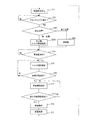
- FIG. 6 is a flowchart for explaining the operation of the engine unit EU shown in FIG.
- FIG. 7A is a view for explaining the movement of the crankshaft 5 in the engine unit EU shown in FIG.
- FIG.7 (b) is a figure explaining the movement of the crankshaft in the case of reverse rotation as a comparative example.
- the operation of the engine unit EU will be described in order from the stop of combustion with reference to FIG. 6 and FIG.
- the control device CT stops the combustion operation of the 4-stroke engine body E (S11). More specifically, the combustion control unit 63 stops the combustion operation of the four-stroke engine body E when an instruction to stop combustion is input.
- An instruction to stop combustion is input from the main switch 17 to the control device CT when the main switch 17 is turned off, for example.
- the control device CT determines the engine stop condition regarding the running state of the vehicle and the rotation state of the crankshaft 5 to execute the combustion stop instruction by itself. For example, normally, after a predetermined time has elapsed since the vehicle stopped, it is determined that the vehicle has stopped, and the engine stops.
- the combustion stop command may be an internal command generated when the control device CT determines that the vehicle has stopped. Further, the combustion stop command may be an external command input by the driver.
- the crankshaft 5 continues to rotate due to inertial force. The crankshaft 5 stops while rotating while decelerating. The inertial force is reduced by, for example, a frictional force. As the inertial force decreases, the frictional force relatively increases.
- FIG. 7 (a) shows a state where the crankshaft has stopped at the stop position P1 after the combustion operation of the four-stroke engine body E has stopped.
- the forward rotation of the crankshaft 5 tends to stop near the compression stroke or the compression stroke. That is, the stop position of the crankshaft 5 is not particularly limited, but tends to be near the compression stroke or the compression stroke.
- the vicinity of the compression stroke is, for example, the intake stroke. Further, the vicinity of the compression stroke is, for example, a position closer to the compression stroke than the exhaust stroke in the intake stroke.
- the stop position P1 where the crankshaft is stopped is in the intake stroke.
- the outer rotor 30 of the three-phase brushless motor SG rotates in conjunction with the rotation of the crankshaft 5.
- a plurality of detected portions 38 (see FIG. 4) provided on the outer rotor 30 are detected by the rotor position detection device 50.
- the control device CT detects the position (angle) of the crankshaft 5 based on the detection of the plurality of detected portions 38 by the rotor position detection device 50. Further, the control device CT detects the rotation of the crankshaft 5 based on the detection of the plurality of detected portions 38 by the rotor position detection device 50. Further, the control device CT detects the rotation stop of the crankshaft 5 based on the detection of the plurality of detected portions 38 by the rotor position detection device 50. More specifically, the control device CT determines that the rotation of the crankshaft 5 has stopped when the plurality of detected portions 38 are not detected by the rotor position detection device 50.
- the rotor position detection device 50 detects a plurality of detected portions 38 that move at positions away from the rotor position detection device 50. Further, the rotor position detecting device 50 detects the plurality of detected portions 38 by an electric signal that changes due to a change in the magnetic state when the plurality of detected portions 38 move. Therefore, the control device CT determines that the crankshaft 5 has stopped when the rotational speed of the crankshaft 5 is low enough that the rotor position detection device 50 cannot detect the movement of the plurality of detected portions 38. Therefore, at this time, the rotational speed of the crankshaft 5 is not limited to 0, and the crankshaft 5 may rotate at a low speed.
- the control device CT After determining that the crankshaft 5 has stopped, the control device CT performs control to rotate the crankshaft 5 in a state where, for example, no start instruction is input.
- the state in which the rotation of the crankshaft 5 is stopped is a state in which the rotation speed of the crankshaft 5 is 0 or substantially 0.
- the state in which the rotation speed of the crankshaft 5 is substantially zero is, for example, that the rotation of the crankshaft 5 is performed at a speed that is not detected by a detection device (for example, the rotor position detection device 50) that detects the rotation of the crankshaft 5.
- the shaft 5 is rotating.
- the state in which the rotational speed of the crankshaft 5 is substantially 0 is, for example, a state in which the crankshaft 5 is rotating at a speed smaller than the maximum rotational speed of the crankshaft 5 in the forward rotation of step S13 in FIG. It is.
- the maximum rotation speed of the crankshaft 5 in S13 of FIG. 6 is the value when the control device CT rotates the crankshaft 5 in a state where no start instruction is input after the four-stroke engine body stops the combustion operation. Is the maximum rotation speed.
- the control device CT moves the crankshaft 5 from the stop position P1 shown in FIG. Is rotated forward until the compression stroke at (S13).
- the control device CT rotates the crankshaft 5 in the forward direction in a state where the combustion operation of the 4-stroke engine body E and the forward rotation of the crankshaft 5 are stopped and no start instruction is input (S13).
- FIG. 7A shows a state in which the crankshaft 5 rotates forward from the stop position P1 to the position P2 in the compression stroke.
- the control device CT performs control without rotating the crankshaft 5 in the reverse direction. To do.
- the control device CT controls the crankshaft 5 without reverse rotation until the combustion operation.
- the control device CT controls the plurality of switching units 611 to 616 of the inverter 61 at least partly from the position where the forward rotation of the crankshaft 5 is stopped to the end of the compression stroke (compression top dead center).
- the three-phase brushless motor SG is rotated with a torque smaller than the maximum torque obtained by the battery 14.
- the control device CT controls the plurality of switching units 611 to 616 of the inverter 61 to control the voltage applied from the battery 14 to the three-phase brushless motor SG, thereby rotating the crankshaft 5 in the forward direction.
- the starter motor control unit 62 (control device CT) turns on / off the plurality of switching units 611 to 616 at a predetermined timing.
- step S ⁇ b> 13 the control device CT rotates the three-phase brushless motor SG with a torque smaller than the maximum torque obtained by the battery 14.
- the control device CT rotates the crankshaft 5 while rotating the three-phase brushless motor SG with a torque that is less than the maximum torque when the crankshaft 5 is normally rotated according to the input of the start instruction (S17). Rotate forward until compression stroke.
- the torque suppression unit 622 of the starter motor control unit 62 turns on / off the plurality of switching units 611 to 616 at a predetermined timing.
- the starter motor control unit 62 performs on / off operations of the switching units 611 to 616 by open loop control.
- the starter motor control unit 62 sequentially energizes the plurality of phases of the stator windings W at a predetermined timing without performing feedback control based on the position of the outer rotor 30.
- the three-phase brushless motor SG exhibits the maximum torque that can be obtained by the battery 14 when the multi-phase stator winding W is sequentially energized at an optimal timing according to the position of the outer rotor 30.
- the torque suppression unit 622 of the starter motor control unit 62 (control device CT) is determined in advance by feedforward control instead of the optimal timing according to the position of the outer rotor 30.
- the switching units 611 to 616 are turned on / off at the same timing.
- the three-phase brushless motor SG rotates with a torque smaller than the maximum torque obtained by the battery 14.
- Turning on / off the switching units 611 to 616 at a predetermined timing means turning on / off the switching units 611 to 616 without using the position information of the outer rotor 30.
- turning on / off the switching units 611 to 616 at a predetermined timing means turning on / off the switching units 611 to 616 without being based on the signal of the rotor position detection device 50.
- turning on / off the switching units 611 to 616 at a predetermined timing means, for example, turning on / off the switching units 611 to 616 without using a magnetic sensor incorporating a semiconductor element.
- the predetermined timing may be changed based on information other than the position information of the outer rotor 30, for example, the temperature or the voltage of the battery 14.
- the multi-phase stator is selected according to the position of the outer rotor 30 detected by the rotor position detection device 50.
- the windings W are sequentially energized. That is, when the control device CT rotates the crankshaft 5 in accordance with the input of the start instruction, the control device CT performs feedback control based on the position of the outer rotor 30, more specifically, the position of the magnetic pole surface 37a with respect to the stator winding W. A plurality of stator windings W are sequentially energized. By the feedback control based on the position of the outer rotor 30, the maximum torque obtained by the battery 14 is obtained.
- the torque suppression unit 622 of the starter motor control unit 62 has a plurality of predetermined timings that do not depend on the position of the magnetic pole surface 37a with respect to the stator winding W.
- the switching units 611 to 616 are turned on / off.
- the control device CT rotates the crankshaft 5 with a torque that is less than the maximum torque when the crankshaft 5 is normally rotated in response to the input of the start instruction.
- step S13 the control device CT turns on and off the plurality of switching units 611 to 616, thereby rotating the crankshaft 5 forward until the compression stroke.
- the control device CT can turn the crankshaft 5 forward until the compression stroke by turning on / off the switching units 611 to 616 a predetermined number of times.
- the crankshaft 5 rotates to the position indicated by P2 in the compression stroke.
- the control device CT sets the number of times of switching on / off the plurality of switching units 611 to 616 to the stop position P1 of the crankshaft 5 when the rotation of the crankshaft 5 is stopped after the combustion operation is stopped (Yes in S12). It is also possible to control according to.
- the control device CT ends the on / off operation of the plurality of switching units 611 to 616. Thereby, the control device CT stops the crankshaft 5 in the compression stroke. In the example shown in FIG. 7A, the crankshaft 5 stops at the position indicated by P2. Since the crankshaft 5 stops in the compression stroke, the rotation of the crankshaft can be reliably started from the compression stroke when the engine is started.
- the control device CT starts the 4-stroke engine body E by rotating the crankshaft 5 with the three-phase brushless motor SG (S15). That is, when the normal rotation (S13) of the crankshaft 5 by the control of the voltage applied to the three-phase brushless motor SG is stopped in the compression stroke and the start instruction is input (Yes in S14), the control device CT The voltage applied from the battery 14 to the three-phase brushless motor SG is controlled to rotate the crankshaft forward (S15). That is, when the forward rotation of the crankshaft 5 is stopped, the control device CT controls the voltage applied from the battery 14 to the three-phase brushless motor SG according to the input of the start instruction to It is rotated forward (S15).
- the control device CT rotates the crankshaft 5 forward from the position of the crankshaft 5 at the time when the start instruction is input (Yes in S14).
- the control device CT rotates the crankshaft 5 forward from the stop position of the crankshaft 5 at the time when the start instruction is input (Yes in S14).
- the start instruction is input from the starter switch 16 to the control device CT when the starter switch 16 is operated, for example.
- the control device CT executes a start instruction by itself by determining a predetermined engine start condition.
- the achievement of the predetermined engine start condition is included in the input of the start instruction.
- the predetermined engine start condition is, for example, an operation of an accelerator operator (not shown).
- the control device CT compresses the crankshaft 5 without stopping the forward rotation in the compression stroke.
- the 4-stroke engine body E is started (S15 to S21). That is, the control device CT stops the combustion operation of the four-stroke engine main body E and the normal rotation of the crankshaft 5 and starts the engine while the crankshaft 5 is normally rotated to the compression stroke in a state where no start instruction is input. Is input, the forward rotation of the crankshaft 5 is continued beyond the compression stroke without being stopped in the compression stroke. As a result, the control device CT starts the four-stroke engine body E (S15 to S21).
- step S15 the control device CT rotates the crankshaft 5 forward from the compression stroke while rotating the three-phase brushless motor SG with a torque smaller than the maximum torque obtained by the battery 14.
- the control device CT continues the control for suppressing the output torque of the three-phase brushless motor SG at least partly from the start of the forward rotation of the crankshaft 5 to the end of the compression stroke. More specifically, the control device CT first performs torque suppression control (S15). More specifically, the torque suppression unit 622 of the starter motor control unit 62 turns on / off the plurality of switching units 611 to 616 at a predetermined timing. The starter motor control unit 62 performs on / off operations of the switching units 611 to 616 by open loop control.
- the starter motor control unit 62 sequentially energizes the plurality of phases of the stator windings W at a predetermined timing without performing feedback control based on the position of the outer rotor 30.
- the torque suppression unit 622 of the starter motor control unit 62 (control device CT) turns on / off the plurality of switching units 611 to 616 at a predetermined timing, so that the torque smaller than the maximum torque obtained by the battery 14 To rotate the crankshaft 5.
- the control device CT performs suppression release control when the rotor position detection device 50 detects the position of the outer rotor 30 (Yes in S16) after the crankshaft 5 starts normal rotation (S17).
- the torque suppression control is performed partly until the end of the compression stroke. Note that the torque suppression control may be performed after the compression stroke.
- the control device CT releases the suppression of the output torque of the three-phase brushless motor SG.
- the control device CT sequentially energizes the plurality of stator windings W at a timing corresponding to the position of the outer rotor 30 in order to release the suppression of the output torque. That is, the control device CT sequentially energizes the plurality of phases of the stator winding W by feedback control based on the position of the outer rotor 30. As a result, the suppression of the output torque of the three-phase brushless motor SG is released, and the maximum torque when the crankshaft 5 is normally rotated according to the input of the start instruction is exhibited. At this time, it is preferable that the control device CT rotates the three-phase brushless motor SG with the maximum torque obtained by the battery 14. By performing the suppression release control (S17), the control device CT shifts to a mode of accelerating the rotation of the outer rotor 30.
- the control device CT starts the combustion operation of the 4-stroke engine body E (S19). More specifically, the combustion control unit 63 of the control device CT controls the combustion operation of the four-stroke engine main body E by controlling the spark plug 29.
- the combustion control unit 63 also controls the injection of the fuel injection device to thereby perform the combustion operation of the 4-stroke engine main body E.
- the start of the combustion operation of the four-stroke engine main body E includes an operation of confirming whether the combustion operation has been normally performed.
- Whether or not the combustion operation is normally performed is determined, for example, by measuring the rotational speed of the crankshaft 5 while the crankshaft 5 rotates a plurality of times, and the measured rotational speed is determined as a case of normal combustion operation. It is determined by whether or not the value exceeds the specified value.
- the control device CT of the present embodiment accelerates the forward rotation of the crankshaft 5 even after starting the combustion operation of the four-stroke engine main body E by rotating the crankshaft 5 forward according to the input of the start instruction ( S19). More specifically, the three-phase brushless motor SG continues the acceleration of the rotation of the crankshaft 5 after starting the combustion operation of the four-stroke engine main body E including the operation for confirming whether the combustion operation is normally performed.
- the control device CT controls the voltage applied from the battery 14 to the three-phase brushless motor SG by controlling the plurality of switching units 611 to 616 of the inverter 61 for a predetermined period after starting the combustion operation.
- the forward rotation of the crankshaft 5 is accelerated.
- the acceleration of the forward rotation of the crankshaft 5 is accelerated as compared with the case of the forward rotation only by the combustion operation of the 4-stroke engine body E.
- the rotation stability of the crankshaft 5 may be low.
- acceleration of the forward rotation of the crankshaft 5 by the three-phase brushless motor SG is continued, thereby stabilizing the forward rotation of the crankshaft 5 due to combustion of the 4-stroke engine body.
- the predetermined period is set to a period (time period) sufficient for stabilizing the rotation of the crankshaft 5.
- a period sufficient for the rotational speed of the crankshaft 5 to reach the idle rotational speed is set.
- the acceleration of the vehicle is assisted by accelerating the forward rotation of the crankshaft 5.
- the control device CT accelerates the forward rotation of the crankshaft 5 by switching the three-phase brushless motor SG from power generation control to power running control.
- control device CT accelerates the forward rotation of the crankshaft 5 for a predetermined period after the start of the four-stroke engine body E is completed. For this reason, the normal rotation of the crankshaft 5 by the combustion operation of the 4-stroke engine main body E can be stabilized. Further, the forward rotation of the crankshaft 5 can be accelerated more rapidly.
- the three-phase brushless motor SG functions as a generator that generates electric current for charging the battery 14 by rotating in conjunction with the rotation of the crankshaft 5 after starting the four-stroke engine body E. That is, when the 4-stroke engine body E starts combustion (S21), the three-phase brushless motor SG is driven by the 4-stroke engine body E and functions as a generator.
- the control device CT controls the current supplied from the plurality of stator windings W to the battery 14 by turning on / off the plurality of switching units 611 to 616.
- the control device CT turns on / off the plurality of switching units 611 to 616 based on the electrical signal of the detection winding 51 of the rotor position detection device 50.
- FIG. 7B shows the movement of the crankshaft in the case of reverse rotation as a comparative example of the present embodiment.
- the crankshaft stops at the stop position P1 as in the case of the present embodiment shown in FIG.
- the crankshaft rotates backward to a position P3 in the expansion stroke.
- the crankshaft starts to rotate forward from a position P3 in the expansion stroke in response to an input of a start instruction.
- FIG. 7A an example of movement is shown in FIG. 7A, after the combustion operation of the four-stroke engine body stops, the start instruction is issued from the stop position P1 where the crankshaft stops. Is shorter than the distance from the position P1 to the position P3 in FIG. 7B.
- FIG. 8 is an explanatory diagram schematically showing the relationship between the crank angle position and the required torque.
- the required torque Ta in the forward rotation is indicated by a solid line.
- the high load region TH is located closer to the compression top dead center (crank angle position is 0 degree) in the compression stroke.
- the low load region TL is included in the intake stroke, the expansion stroke, and the exhaust stroke.
- the necessary torque Tb in the reverse rotation is indicated by a broken line.
- the crankshaft rotates in the reverse direction as shown by the broken line in FIG. 8, the high load region is included in the expansion stroke, not the compression stroke.
- the lower part of the graph of FIG. 8 shows the crankshaft movement M1 in the forward rotation shown in FIG. 7A and the crank in the reverse rotation shown in FIG. 7B as a comparative example. Shaft movement M2 is shown.
- crankshaft movement M2 in the case of reverse rotation will be described as a comparative example.
- the crankshaft stops at the compression stroke or the stop position P1 in the vicinity of the compression stroke the crankshaft rotates in the reverse direction to the expansion stroke position P3 and stops. Thereafter, the crankshaft rotates normally in response to the input of the start instruction, so that the rotation speed of the crankshaft is increased before reaching the high load region.
- the crankshaft reversely rotates through the intake stroke and the exhaust stroke to the expansion stroke. Further, when the crankshaft rotates in the reverse direction, a high load region is generated in the exhaust stroke. At the time of reverse rotation of the crankshaft, if the crankshaft gets over the maximum load position in the high load region, the crankshaft moves in the compression stroke. If the reversely rotating crankshaft moves in the compression stroke, there is no merit of reversely rotating, and on the contrary, power and time for shifting from reversely rotating to normal rotating are required. Therefore, when the crankshaft rotates in the reverse direction, it is required to avoid the crankshaft moving in the compression stroke.
- crankshaft cannot be brought close enough to the maximum load position near the compression top dead center (0 degree). Since it is difficult to bring the crankshaft sufficiently close to the maximum load position during reverse rotation of the crankshaft, the distance L4 for forward rotation from the position P3 at which normal rotation starts to the maximum load position in response to the input of the start instruction is short. For this reason, the inertial force obtained by the forward rotation according to the input of the start instruction is relatively small.
- the crankshaft 5 is moved forward to the position P2 in the compression stroke by driving the three-phase brushless motor SG. Rotate. Thereafter, when the crankshaft 5 starts to rotate in response to the input of the start instruction, the crankshaft 5 gradually increases in speed from the stopped state.
- the crankshaft 5 passes through the compression stroke at a low speed after the rotation starts. Since the crankshaft 5 passes through the compression stroke at a low speed, the crankshaft 5 is hardly affected by the compression reaction force of the gas.
- the crankshaft 5 can quickly get over the load in the high load region of the compression stroke. After passing through the compression stroke, the crankshaft rotates forward over a wide low load region from the expansion stroke to the compression stroke, and reaches the second high load region. That is, a long approach section L2 for acceleration is ensured. Therefore, the three-phase brushless motor SG can increase the rotational speed of the crankshaft 5 before reaching the second high load region. And the high load area of the 2nd time can be overcome using both the large inertial force accompanying the high rotational speed and the output torque of the three-phase brushless motor. Therefore, the output torque of the three-phase brushless motor SG can be suppressed and the three-phase brushless motor can be downsized.
- the position P2 is a position for starting the 4-stroke engine main body E with a small output torque.
- the position P2 is a position within the compression stroke.
- the position P2 is, for example, a position near the compression top dead center in the compression stroke.
- the control device CT controls the voltage applied from the battery 14 to the three-phase brushless motor SG by controlling the plurality of switching units 611 to 616 of the inverter 61,
- the crankshaft 5 is rotated forward from the stop position P1 to the compression stroke position P2.
- the section L1 that moves in the forward rotation is shorter than the section L3 that moves in the reverse rotation. Therefore, the crankshaft 5 can be moved to a position where the four-stroke engine main body E can be easily started with a small torque in a short time as compared with the case where the crankshaft is reversely rotated to the expansion stroke.
- crankshaft 5 stopped at the stop position P1 is rotated forward to the compression stroke position P2 by controlling the voltage applied to the three-phase brushless motor SG, for example, by the inertia force of the combustion operation of the four-stroke engine body E Compared to the case of normal rotation, the movement of the crankshaft to the position P2 is easier to control. Therefore, the crankshaft can be moved in a short time to a position where the 4-stroke engine body E can be easily started.
- the four-stroke engine main body E having a high load region and a low load region is provided between the four strokes, and the time until restart after the combustion stop instruction is reduced. It is possible to achieve both vehicle mounting properties.
- control device CT rotates the crankshaft 5 forward to the compression stroke while rotating the three-phase brushless motor SG with a torque smaller than the maximum torque obtained by the battery 14 in a state where no start instruction is input. (Step S13 in FIG. 6).
- control device CT rotates the crankshaft 5 forward from the compression stroke while rotating the three-phase brushless motor SG at a torque lower than the maximum torque obtained by the battery 14 when starting the four-stroke engine body E. (Step S15 in FIG. 6).
- the control device CT rotates the three-phase brushless motor SG with a torque smaller than the maximum torque obtained by the battery 14 at least partly between the crankshaft 5 starting to rotate forward and the end of the compression stroke. .
- the crankshaft 5 starts to rotate forward from the compression stroke at a lower speed than when rotating at the maximum torque obtained by the battery 14, for example. Therefore, the crankshaft 5 can more easily get over the load in the high load region of the compression stroke.
- crankshaft 5 tends to pass the load at a low speed is that in the four-stroke engine body E, the amount of gas leaking from the combustion chamber to the outside of the combustion chamber increases, and the magnitude of the load caused by the compression reaction force decreases This is probably because of this.
- the crankshaft 5 that has passed at least the compression stroke rotates normally over almost the entire low load region from the expansion stroke to the compression stroke, and then reaches the second high load region.
- region of the 2nd time can be overcome using both the big inertia force accompanying high rotational speed, and the output torque of the three-phase brushless motor SG.
- the number of magnetic pole surfaces 37 a included in the rotor 30 of the three-phase brushless motor SG is larger than 2/3 of the tooth portion 43.
- the frequency of change in voltage applied to each of the windings W is high by the control device CT controlling the switching units 611 to 616.
- the control device CT controlling the switching units 611 to 616.
- the frequency of this pulse is high. Since the frequency of the voltage applied to each of the windings W is high, the frequency of the pulsation of torque applied when the three-phase brushless motor SG rotates the crankshaft 5 forward is high. By receiving the pulsation of torque having a high frequency, the crankshaft 5 can easily get over the load in the high load region.
- the three-phase brushless motor SG functions as a generator that generates electric current for charging the battery 14 by rotating in conjunction with the rotation of the crankshaft 5 after the four-stroke engine body E is started.
- the stator winding W of the three-phase brushless motor SG also serving as a generator function is subject to structural restrictions for charging the battery 14. For example, in order to suppress an excessive charging current, the performance as a three-phase brushless motor SG is limited.
- the crankshaft 5 reaches the maximum load position at a low rotational speed with an output torque smaller than the maximum torque, and accelerates in a sufficient section to the second maximum load position.
- the three-phase brushless motor SG can be miniaturized while simplifying the configuration by combining the three-phase brushless motor SG with the starter motor and the generator.
- the 4-stroke engine main body E included in the engine unit EU of the present embodiment has a decompression device (decompression).
- a decompression device D is schematically shown in FIG.
- the decompression device D discharges a part of the gas in the combustion chamber by opening a valve provided in the 4-stroke engine main body E in a part of the compression stroke. That is, the decompression device D releases the pressure in the combustion chamber during a part of the compression stroke. Thereby, the influence of the compression reaction force of the gas which the crankshaft 5 receives is reduced. That is, the load for rotating the crankshaft 5 is reduced in the high load region.
- the valve is kept closed in the compression stroke, so that a high load is generated in a high load region.
- the decompression device D operates when the rotational speed of the crankshaft 5 is lower than a predetermined threshold value.
- the threshold value is lower than the rotation speed at which the combustion operation of the 4-stroke engine main body E is possible. Therefore, the decompression device D operates during a part of the period in which the control device CT controls the voltage applied from the battery 14 to the three-phase brushless motor SG to rotate the crankshaft 5 in the forward direction.
- FIG. 9 is an explanatory view schematically showing the relationship between the crank angle position and the required torque in the engine unit EU of the second embodiment of the present invention.
- the control device CT stops the combustion operation of the 4-stroke engine body E and the normal rotation of the crankshaft 5 and then stops the combustion operation of the 4-stroke engine body E and the crankshaft 5.
- the forward rotation of the crankshaft 5 is stopped and the crankshaft 5 is rotated forward from the stop position to the compression stroke in 4 strokes in a state where no start instruction is input.
- the control device CT rotates the crankshaft 5 from the stop position to the compression stroke in a state where no start instruction is input, the decompression device D operates. For this reason, as shown in FIG. 9, a plurality of maximums (peaks) Q1 and Q2 occur in the required torque, that is, the load. The load is reduced between the plurality of maximums Q1 and Q2.
- the control device CT controls the crankshaft 5 to a load maximum Q2 closest to the compression top dead center among the maximum loads Q1 and Q2 of the plurality of loads that come before the compression top dead center when the crankshaft 5 is rotating forward. A forward rotation is made to a position between the load maximum Q1 located next to the load maximum Q2 closest to the compression top dead center.
- the control device CT stops the crankshaft 5 at a position between the maximum Q2 and the maximum Q1.
- the control device CT rotates the crankshaft 5 from the position of the crankshaft 5 at the time when the start instruction is input. Specifically, the control device CT controls the voltage applied from the battery 14 to the three-phase brushless motor SG to rotate the crankshaft 5 from the position between the maximum Q2 and the maximum Q1. Since the pressure in the combustion chamber is released by the decompression device D, the load for rotating the crankshaft 5 is reduced. For this reason, even if the output torque of the three-phase brushless motor SG is smaller, it is possible to quickly get over the load in the high load region. Accordingly, the time until the 4-stroke engine body E is restarted is shortened.
- the control device CT causes the crankshaft 5 to rotate forward when the start instruction is not input, and the control device CT causes the crankshaft 5 to rotate forward when the start instruction is input. You may operate in both periods. Further, the decompression device D may operate in one of these periods. Further, the decompression device D may operate in a part of both of these periods.
- the control device CT rotates the crankshaft 5 forward to the compression stroke when no start instruction is input, and when the start instruction is input, the crankshaft 5 at the time when the start instruction is input. Rotate the crankshaft forward from the position. That is, the control device CT stops the rotation of the crankshaft 5 in the compression stroke, and starts the rotation of the crankshaft 5 from the compression stroke.
- the crankshaft 5 passes through the compression stroke at a low rotational speed.
- the decompression device D opens the valve during a part of the compression stroke, and releases the pressure in the combustion chamber. When the decompression device D opens the valve in part of the compression stroke and releases the pressure in the combustion chamber, the crankshaft 5 is rotating at a low rotational speed in the compression stroke. For this reason, sufficient time for releasing the pressure in a combustion chamber is ensured. As a result, the pressure drop in the combustion chamber is large. Accordingly, the load for rotating the crankshaft 5 is reduced.
- the decompression device D ensures a sufficient time for releasing the pressure in the combustion chamber. For this reason, the decompression device D is highly effective in reducing the rotational load. Therefore, even if the output torque of the three-phase brushless motor SG is small, it is possible to quickly get over the load in the high load region. According to the present embodiment, it is possible to achieve both shortening of the time until restart after the combustion stop instruction and further mountability to the vehicle.
- the load in at least a part of the high load region is reduced by the operation of the decompression mechanism. Therefore, after the start command is input, the load necessary to rotate the crankshaft is increased. Reduced. Therefore, the output torque of the three-phase brushless motor SG can be suppressed and the three-phase brushless motor can be downsized.
- FIG. 10 is a flowchart for explaining the operation of the engine unit EU according to the third embodiment.
- FIG. 11 is a view for explaining the movement of the crankshaft 5 in the engine unit EU according to the third embodiment.
- the control device CT inputs a start instruction according to the position where the rotation of the crankshaft 5 that has continued since the stop of the combustion operation of the four-stroke engine main body E is stopped (S12 in FIG. 10).
- the forward rotation and the reverse rotation of the crankshaft 5 in a state where there is no rotation are switched (S301). For example, when the position where the forward rotation of the crankshaft 5 that has continued since the stop of the combustion operation of the 4-stroke engine body E is within the first range R1 (see FIG.
- the control device CT gives a start instruction In a state where there is no input, the crankshaft 5 is rotated forward to the compression stroke (S302). When the position where the forward rotation of the crankshaft 5 that has continued from when the combustion operation of the 4-stroke engine main body E stops is within the second range R2 within the 4-stroke, the control device CT does not input a start instruction.
- the shaft is reversely rotated (S303).
- the control device CT detects the position of the crankshaft 5 based on the detection of the plurality of detected portions 38 by the rotor position detection device 50 (see FIG. 4).
- the operations in steps S301 to S303 described above are different from those in the first embodiment. The remaining operations are the same as in the first embodiment.
- FIG. 11 shows an example of both a case where the crankshaft rotates forward and a case where the crankshaft rotates reversely without input of a start instruction.
- FIG. 11 shows an example of the first range R1 and the second range R2 described above.
- the first range R1 extends in the forward rotation direction from the start point Ra to the end point Rb.
- the start point Ra of the first range R1 is set within a range from the compression top dead center (0 degrees) to the exhaust top dead center (360 degrees) in the forward rotation direction.
- the end point Rb of the first range R1 is set within the compression stroke.
- the second range R2 extends in the forward rotation direction from the compression top dead center (0 degree) to the start point Ra of the first range R1.
- the second range R2 is closer to the compression top dead center than the first range R1 in the reverse rotation direction.
- the forward rotation and the reverse rotation of the crankshaft 5 in a state where no start instruction is input are switched according to the position where the forward rotation of the crankshaft 5 that has continued since the stop of the combustion operation is stopped.
- the control device CT reversely rotates the crankshaft 5 to the position of P6 shown in FIG. 11, for example, in the expansion stroke.
- the crankshaft 5 starts the normal rotation from the position where the reverse rotation is stopped.
- the crankshaft 5 starts normal rotation from the position of, for example, P6 in the expansion stroke.
- the crankshaft 5 rotates in the reverse direction in the absence of an input of a start instruction, so that a long running section is ensured before reaching the next high load region during normal rotation according to the input of the start instruction.
- the crankshaft 5 even when the forward rotation of the crankshaft 5 that has continued from when the combustion operation of the four-stroke engine main body E is stopped is stopped in the second range R2, the crankshaft is not input without a start instruction being input. By rotating 5 reversely, the crankshaft can be moved to a position where the 4-stroke engine body can be easily started. Therefore, according to the present embodiment, it is possible to further shorten the time until restart after the combustion stop instruction.
- FIG. 12 is a flowchart for explaining the operation of the engine unit EU according to the fourth embodiment.
- the control device CT when the normal rotation of the crankshaft 5 that has continued since the combustion operation of the four-stroke engine main body E is stopped in the compression stroke (“compression stroke” in S401), the control device CT is started.
- the forward rotation (S13) of the crankshaft 5 in a state where no instruction is input is omitted.
- the control device CT does not input a start instruction.
- the crankshaft 5 is rotated forward (S13) in the state.
- step S401 the other operations of step S401 described above are the same as in the first embodiment.
- the crankshaft 5 does not move the 4-stroke engine main body E even if the output torque of the three-phase brushless motor SG is small. Easy to start.
- the forward rotation of the crankshaft 5 stops at a position where the four-stroke engine main body E can be easily started, the forward rotation of the crankshaft in a state where no start instruction is input is omitted. For this reason, it is possible to shorten the time until the start of rotation of the crankshaft when the start instruction is input. Therefore, it is possible to further shorten the time until restart after the combustion stop instruction.
- FIG. 13 is a block diagram showing an electrical basic configuration according to the engine unit EU of the fifth embodiment.
- the rotor position detection device 850 is configured by a Hall IC.
- the rotor position detection device 850 detects the magnetic pole surface 37 a provided on the outer rotor 30.
- the control device CT determines the position of the outer rotor 30 based on a change in the electrical signal output from the rotor position detection device 850.
- the control device CT controls the plurality of switching units 611 to 616 of the inverter 61 based on the position of the outer rotor 30. Thereby, the control device CT controls the rotation of the three-phase brushless motor SG.
- the control device CT of the present embodiment turns on / off the plurality of switching units 611 to 616 according to the position of the outer rotor 30 detected by the rotor position detection device 850, not at a predetermined timing. That is, the control device CT of the present embodiment turns on / off the plurality of switching units 611 to 616 by feedback control based on the position of the outer rotor 30.
- control device CT of the present embodiment controls the voltage (voltage value) applied from the battery 14 to the three-phase brushless motor SG by controlling the plurality of switching units 611 to 616 of the inverter 61. More specifically, each of the cranking control unit 8621 and the torque suppression unit 8622 of the starter motor control unit 862 controls the plurality of switching units 611 to 616 of the inverter 61, so that the battery 14 changes to the three-phase brushless motor SG. The applied voltage (voltage value) is controlled. In the present embodiment, as a control, not only the energization and deactivation of the stator winding W are switched, but also the voltage value is controlled.
- the control device CT performs pulse width modulation (PWM) control on the plurality of switching units 611 to 616 of the inverter 61.
- the control device CT turns on the plurality of switching units 611 to 616 of the inverter 61 with a pulse width modulated signal.
- the control device CT repeats an energization period of 120 degrees in the electrical angle and a non-energization period of 60 degrees following the energization period.
- the control device CT turns on the switching unit of the phase corresponding to the energization period among the three phases with a pulse width modulated signal.
- the period of the pulse is shorter than the repetition period of the energization period and the non-energization period.
- the control device CT and the inverter 61 of the present embodiment control the average voltage (voltage value) applied to the stator winding W of the three-phase brushless motor SG by controlling the duty ratio of the pulse width modulated signal.
- the average voltage value is, for example, a time average value of voltage per unit time.
- the unit time is, for example, a time corresponding to the energization period. That is, the control device CT not only switches energization and energization stop for the stator winding W, but also controls the voltage value applied to the stator winding W during the energization period.
- the control device CT rotates the crankshaft 5 in the forward direction from the state where the combustion operation of the 4-stroke engine main body E and the forward rotation of the crankshaft 5 are stopped. At this time, the control device CT controls the plurality of switching units 611 to 616 of the inverter 61 at least partly from the position where the forward rotation of the crankshaft 5 is stopped to the end of the compression stroke, The three-phase brushless motor SG is rotated with a torque smaller than the maximum torque obtained by the battery 14. The control device CT of the present embodiment controls the plurality of switching units 611 to 616 of the inverter 61 at least partly until the end of the compression stroke, thereby applying a voltage applied from the battery 14 to the three-phase brushless motor SG.
- the control device CT of the present embodiment controls the plurality of switching units 611 to 616 of the inverter 61 at least during a period in which the crankshaft 5 is normally rotated from the state where no start instruction is input to the compression stroke.
- the voltage applied to the three-phase brushless motor SG is made lower than the voltage of the battery 14.
- the control device CT controls the plurality of switching units 611 to 616 of the inverter 61 at least partly during the forward rotation of the crankshaft 5 from the state where no start instruction is input to the compression stroke.
- the motor SG is rotated with a torque smaller than the maximum torque obtained by the battery 14.
- the control device CT applies the voltage applied to the three-phase brushless motor SG in the forward rotation of step S13 shown in FIG. 6 when the crankshaft 5 rotates forward according to the input of the start instruction ( S17) Lower than the voltage applied to the three-phase brushless motor SG.
- the voltage applied to the three-phase brushless motor SG is equal to the voltage of the battery 14 when the duty ratio of the signal for controlling the switching units 611 to 616 is 100%.
- the three-phase brushless motor SG exhibits the maximum torque obtained by the battery 14.
- the control device CT of the present embodiment makes the voltage applied to the three-phase brushless motor SG lower than the voltage of the battery 14 by making the duty ratio of the signal for controlling the switching units 611 to 616 lower than 100%. As a result, the three-phase brushless motor SG rotates with a torque smaller than the maximum torque obtained by the battery 14.
- the control device CT rotates the crankshaft 5 forward to the compression stroke while rotating the three-phase brushless motor SG with a torque that is lower than the maximum torque obtained by the battery 14. Therefore, according to the present embodiment, since the crankshaft 5 passes through the compression stroke at a low speed, the crankshaft 5 is hardly affected by the gas compression reaction force. Therefore, according to the present embodiment, as in the case of the first embodiment, the resistance due to the compression reaction force to the rotation of the crankshaft 5 can be suppressed, so that the crankshaft 5 can be moved to the compression stroke in a shorter time. Can do. Therefore, the time until restart is more reliably shortened.
- the control device CT of the present embodiment receives a start instruction in a state where the combustion operation of the four-stroke engine main body E and the forward rotation of the crankshaft 5 are stopped, and then rotates the crankshaft 5 forward until the compression stroke. At least in part, the voltage applied from the battery 14 to the three-phase brushless motor SG is made lower than the voltage of the battery 14.
- the control device CT controls the plurality of switching units 611 to 616 of the inverter 61 so that the voltage applied from the battery 14 to the three-phase brushless motor SG is lower than the voltage of the battery 14 to rotate the crankshaft 5 in the forward direction.
- control device CT reduces the duty ratio of the signal for controlling the plurality of switching units 611 to 616 to less than 100% in the torque suppression control in step S15 shown in FIG.
- the voltage applied to is lower than the voltage of the battery 14.
- crankshaft can be moved to the compression stroke in a shorter time. it can. Therefore, similarly to the first embodiment, it is possible to further shorten the time until restart after the combustion stop instruction.
- FIG. 14 is an external view showing a vehicle on which any of the engine units of the first embodiment to the fifth embodiment is mounted.
- the vehicle A shown in FIG. 14 includes an engine unit EU, a vehicle body 101, wheels 102 and 103, and a battery 14.
- the engine unit EU may be the engine unit EU according to any of the first to fifth embodiments.
- the engine unit EU mounted on the vehicle A drives the wheel 103 that is a driving wheel, and rotates the wheel 103 to cause the vehicle A to travel.
- the vehicle A shown in FIG. 14 has a heat resistance while ensuring early startability, and has a simple structure and a high vehicle mountability. Therefore, the vehicle A as a whole can be made compact.
- the vehicle A shown in FIG. 14 is a motorcycle.
- the vehicle of the present invention is not limited to a motorcycle.
- Examples of the vehicle of the present invention include scooter type, moped type, off-road type, and on-road type motorcycles.
- the straddle-type vehicle is not limited to a motorcycle, and may be, for example, an ATV (All-Train Vehicle).
- the vehicle according to the present invention is not limited to a saddle-ride type vehicle, and may be a four-wheel vehicle having a passenger compartment.
- control device CT may detect rotation and stoppage of the crankshaft 5 by detection means other than the rotor position detection device 50.
- the engine unit may include a Hall IC or a rotary encoder, and the control device may detect the rotation and the rotation stop of the crankshaft 5 by detecting an output signal of the Hall IC or the rotary encoder.
- control device CT that decreases the output torque suppression rate when the crankshaft 5 reaches the maximum load position is shown.
- the control device of the present invention is not limited to this. For example, after the crankshaft reaches the maximum load position, the control device continues the rotation with a torque smaller than the maximum torque obtained by the battery 14 until the ignition of the engine. May be.
- the three-phase brushless motor SG is smaller than the maximum torque obtained by the battery 14 while the crankshaft 5 is normally rotated from the state where no start instruction is input to the compression stroke.
- a control device CT that rotates by torque is shown.
- the control device of the present invention is not limited to this, and for example, the control device is a part of the three-phase brushless motor SG that is partly rotated while the crankshaft 5 is normally rotated from the state where no start instruction is input to the compression stroke. You may rotate with the torque smaller than the maximum torque obtained with the battery 14.
- the voltage applied to the three-phase brushless motor SG is made lower than the voltage of the battery 14 while the crankshaft 5 is normally rotated from the state where no start instruction is input to the compression stroke.
- a control device CT is shown.
- the control device of the present invention is not limited to this, and for example, the control device is applied to the three-phase brushless motor SG during a part during the forward rotation of the crankshaft 5 from the state where no start instruction is input to the compression stroke.
- the voltage to be applied may be lower than the battery voltage.
- control device the control to make the voltage applied to the three-phase brushless motor SG lower than the voltage of the battery 14 until the crankshaft passes the compression stroke after receiving the start instruction.
- An apparatus CT was shown.
- the control device of the present invention is not limited to this.
- the control device applies a part to the three-phase brushless motor SG from the time when the start instruction is input until the crankshaft passes the compression stroke.
- the voltage may be lower than the voltage of the battery 14.
- a control device CT that lowers the duty ratio of the signal for controlling the switching units 611 to 616 to less than 100% is provided. Indicated.
- the control device of the present invention is not limited to this.
- the control device includes a voltage limiting circuit disposed between the switching unit and the battery, and the voltage applied to the switching unit by the voltage limiting circuit is the voltage of the battery. It may be lower.
- the engine of the present invention is not particularly limited as long as the engine has a high load region and a low load region. That is, a multi-cylinder engine may be used. Examples other than the present embodiment include engines such as an in-line single cylinder, a parallel two-cylinder, an in-line two-cylinder, a V-type two-cylinder, and a horizontally opposed two-cylinder.
- the number of cylinders of the multi-cylinder engine is not particularly limited, and the multi-cylinder engine may be, for example, a four-cylinder engine.
- some four-cylinder engines do not have a low load region, such as a four-cylinder engine in which the compression stroke of each cylinder occurs at equal intervals (a four-cylinder engine that performs explosion at equal intervals).
- region does not correspond to the engine of this invention.
- a Vehicle CT Controller E Four-stroke engine main body EU Engine unit SG Three-phase brushless motor 5 Crankshaft 29 Spark plugs 62, 862 Starter motor controller 63 Combustion controller 61 Inverters 611 to 616 Switching unit
Landscapes
- Engineering & Computer Science (AREA)
- Chemical & Material Sciences (AREA)
- Combustion & Propulsion (AREA)
- Mechanical Engineering (AREA)
- General Engineering & Computer Science (AREA)
- Control Of Vehicle Engines Or Engines For Specific Uses (AREA)
- Output Control And Ontrol Of Special Type Engine (AREA)
- Control Of Motors That Do Not Use Commutators (AREA)
- Hybrid Electric Vehicles (AREA)
Abstract
Description
(1) 車両に搭載されるエンジンユニットであって、
前記エンジンユニットは、
4ストロークの間に、クランクシャフトを回転させる負荷が大きい高負荷領域と、前記クランクシャフトを回転させる負荷が前記高負荷領域の負荷より小さい低負荷領域とを有する4ストロークエンジン本体と、
前記車両が備えるバッテリにより駆動され、始動指示の入力に応じて前記クランクシャフトを正回転させて前記4ストロークエンジン本体を始動する三相ブラシレスモータと、
前記バッテリから前記三相ブラシレスモータに印加する電圧を制御する複数のスイッチング部を備えたインバータと、
前記インバータに備えられた前記複数のスイッチング部を制御することによって、前記バッテリから前記三相ブラシレスモータに印加される電圧を制御するスタータモータ制御部と、前記4ストロークエンジン本体の燃焼動作を制御する燃焼制御部とを含む制御装置と
を備え、
前記制御装置は、前記4ストロークエンジン本体の燃焼動作と前記クランクシャフトの正回転とが停止した後、前記4ストロークエンジン本体の燃焼動作と前記クランクシャフトの正回転とが停止し、かつ前記始動指示の入力がない状態で、前記インバータの前記複数のスイッチング部を制御することによって、前記バッテリから前記三相ブラシレスモータに印加される電圧を制御して、前記クランクシャフトを、停止位置から前記4ストロークにおける圧縮行程まで正回転させて、前記圧縮行程で停止させ、
前記三相ブラシレスモータに印加される電圧の制御による前記クランクシャフトの正回転が前記圧縮行程で停止した後、前記始動指示の入力があった場合、前記バッテリから前記三相ブラシレスモータに印加される電圧を制御して、前記始動指示が入力された時点における前記クランクシャフトの位置から前記クランクシャフトを正回転させる。 The present invention employs the following configuration in order to solve the above-described problems.
(1) An engine unit mounted on a vehicle,
The engine unit is
A four-stroke engine main body having a high load region in which a load for rotating the crankshaft is large during four strokes, and a low load region in which the load for rotating the crankshaft is smaller than the load in the high load region;
A three-phase brushless motor that is driven by a battery included in the vehicle and starts the four-stroke engine body by rotating the crankshaft in accordance with an input of a start instruction;
An inverter including a plurality of switching units for controlling a voltage applied from the battery to the three-phase brushless motor;
A starter motor control unit that controls a voltage applied from the battery to the three-phase brushless motor by controlling the plurality of switching units provided in the inverter, and a combustion operation of the four-stroke engine main body. A control device including a combustion control unit,
The control device stops the combustion operation of the 4-stroke engine body and the forward rotation of the crankshaft after the combustion operation of the 4-stroke engine body and the forward rotation of the crankshaft are stopped, and the start instruction In the state where there is no input, the voltage applied from the battery to the three-phase brushless motor is controlled by controlling the plurality of switching units of the inverter, and the crankshaft is moved from the stop position to the four strokes. In the forward direction until the compression stroke, and stop at the compression stroke,
When the start instruction is input after the forward rotation of the crankshaft by the control of the voltage applied to the three-phase brushless motor is stopped in the compression stroke, it is applied from the battery to the three-phase brushless motor. By controlling the voltage, the crankshaft is rotated forward from the position of the crankshaft at the time when the start instruction is input.
従って(1)のエンジンユニットによれば、4ストロークの間に高負荷領域と低負荷領域とを有する4ストロークエンジン本体を備え、燃焼停止指示の後、再始動するまでの時間の短縮と車両への搭載性を両立させることができる。 According to the configuration of (1), after the combustion operation of the four-stroke engine main body and the forward rotation of the crankshaft are stopped, a plurality of switching units of the inverter are controlled to be applied from the battery to the three-phase brushless motor. By controlling the voltage, the crankshaft is rotated forward until the compression stroke in the four strokes including the high load region and the low load region. When the crankshaft is rotated forward by controlling the voltage applied to the three-phase brushless motor, for example, the crankshaft is moved to the target position as compared with the case of forward rotation by the inertia force of the combustion operation of the 4-stroke engine body. Easy to control. For this reason, the crankshaft can be moved in a short time to a position where the 4-stroke engine body can be easily started with a small output torque.
Therefore, according to the engine unit of (1), a four-stroke engine main body having a high load region and a low load region is provided during four strokes, and after the combustion stop instruction, the time until restart is reduced and the vehicle is moved. Can be made compatible.
前記4ストロークエンジン本体は、燃焼室と、前記圧縮行程において前記燃焼室の中の圧力を逃がすデコンプレッション装置とを備え、
前記デコンプレッション装置は、前記制御装置が、前記バッテリから前記三相ブラシレスモータに印加される電圧を制御して、前記クランクシャフトを正回転させる期間の少なくとも一部で動作する。 (2) The engine unit of (1),
The four-stroke engine body includes a combustion chamber, and a decompression device that releases pressure in the combustion chamber in the compression stroke,
The decompression device operates in at least a part of a period in which the control device controls a voltage applied from the battery to the three-phase brushless motor to rotate the crankshaft forward.
前記三相ブラシレスモータは、周方向に並んだ複数の歯部及び前記複数の歯部のそれぞれに巻き付いた巻線を有するステータと、前記ステータと対向して配置され前記クランクシャフトと連動して回転するロータとを備え、前記ロータは、前記複数の歯部の数の2/3よりも多い磁極面を有し、
前記制御装置は、前記インバータの前記複数のスイッチング部を制御することによって、前記バッテリから前記三相ブラシレスモータの前記複数の巻線のそれぞれに印加される電圧を制御して、前記クランクシャフトを正回転させる。 (3) The engine unit according to (1) or (2),
The three-phase brushless motor includes a plurality of teeth arranged in a circumferential direction and a stator having a winding wound around each of the plurality of teeth, and is arranged to face the stator and rotates in conjunction with the crankshaft. And the rotor has a pole face that is greater than 2/3 of the number of the plurality of tooth portions,
The control device controls the plurality of switching units of the inverter to control the voltage applied from the battery to each of the plurality of windings of the three-phase brushless motor, thereby correcting the crankshaft. Rotate.
前記制御装置は、前記圧縮行程の終わりまでの間の少なくとも一部で、前記インバータの前記複数のスイッチング部を制御することによって前記三相ブラシレスモータを、前記バッテリで得られる最大トルクよりも小さいトルクで正回転させる。 (4) The engine unit according to any one of (1) to (3),
The control device controls the plurality of switching units of the inverter to control the three-phase brushless motor at least partly until the end of the compression stroke, so that the torque smaller than the maximum torque obtained by the battery is reduced. Rotate forward with.
前記制御装置は、前記圧縮行程の終わりまでの間の少なくとも一部で、前記インバータの前記複数のスイッチング部を制御することによって前記バッテリから前記三相ブラシレスモータに印加する電圧を前記バッテリの電圧より低くして前記クランクシャフトを正回転させる。 (5) The engine unit according to any one of (1) to (4),
The control device controls a voltage applied from the battery to the three-phase brushless motor by controlling the plurality of switching units of the inverter at least partly until the end of the compression stroke, based on the voltage of the battery. Lower the crankshaft and rotate it forward.
前記制御装置は、前記4ストロークエンジン本体の燃焼動作と前記クランクシャフトの正回転とが停止し、かつ前記始動指示の入力がない状態で、前記インバータの前記複数のスイッチング部を制御することによって前記三相ブラシレスモータに印加される電圧を制御して前記クランクシャフトを前記圧縮行程まで正回転させる途中で前記始動指示の入力があった場合、前記クランクシャフトの正回転を前記圧縮行程で停止させずに前記圧縮行程を超えて継続させることにより、前記4ストロークエンジン本体を始動させる。 (6) The engine unit according to any one of (1) to (5),
The control device controls the plurality of switching units of the inverter while the combustion operation of the four-stroke engine main body and the forward rotation of the crankshaft are stopped and the start instruction is not input. If the start instruction is input during the normal rotation of the crankshaft to the compression stroke by controlling the voltage applied to the three-phase brushless motor, the forward rotation of the crankshaft is not stopped in the compression stroke. The 4-stroke engine main body is started by continuing the compression stroke beyond the compression stroke.
前記制御装置は、前記4ストロークエンジン本体の燃焼動作の停止時から続く前記クランクシャフトの正回転が前記圧縮行程で停止した場合には、前記始動指示の入力がない状態における前記クランクシャフトの正回転を省略する。 (7) The engine unit according to any one of (1) to (5),
When the forward rotation of the crankshaft that has continued from the stop of the combustion operation of the four-stroke engine main body is stopped during the compression stroke, the control device performs forward rotation of the crankshaft in a state where the start instruction is not input. Is omitted.
前記制御装置は、前記4ストロークエンジン本体の燃焼動作の停止時から続く前記クランクシャフトの正回転が停止した位置に応じて、前記始動指示の入力がない状態における前記クランクシャフトの正回転と逆回転を切換える。 (8) The engine unit according to any one of (1) to (5),
The control device reversely rotates forward and reverse the crankshaft in a state where the start instruction is not input in accordance with a position where the forward rotation of the crankshaft that has continued from when the combustion operation of the 4-stroke engine main body is stopped. Is switched.
前記制御装置は、前記4ストロークエンジン本体の燃焼動作の停止時から続く前記クランクシャフトの正回転が停止した位置が前記4ストローク内の第一範囲にある時には、前記始動指示の入力がない状態で前記クランクシャフトを前記圧縮行程まで正回転させ、前記4ストロークエンジン本体の燃焼動作の停止時から続く前記クランクシャフトの正回転が停止した位置が前記4ストローク内の第二範囲にある時には、前記始動指示の入力がない状態で前記クランクシャフトを逆回転させ、前記第一範囲は、圧縮上死点から正回転方向に排気上死点に至る範囲内の始点から、前記圧縮行程内の終点まで、正回転方向に広がり、前記第二範囲は、圧縮上死点から、前記第一範囲の始点まで正回転方向に広がる。 (9) The engine unit of (8),
When the position where the forward rotation of the crankshaft that has continued from the stop of the combustion operation of the 4-stroke engine main body is within the first range within the 4-stroke, the control device is in a state in which the start instruction is not input. The crankshaft is rotated forward until the compression stroke, and when the position where the forward rotation of the crankshaft that has continued from the stop of the combustion operation of the 4-stroke engine body is within the second range within the 4-stroke is The crankshaft is reversely rotated in the absence of an instruction, and the first range is from the start point in the range from the compression top dead center to the exhaust top dead center in the forward rotation direction to the end point in the compression stroke. The second range extends in the forward rotation direction from the compression top dead center to the start point of the first range.
前記制御装置は、
前記始動指示の入力に応じて前記クランクシャフトを正回転させることによって前記4ストロークエンジン本体の燃焼動作を開始させた後、予め定められた期間、前記インバータの前記複数のスイッチング部を制御することによって、前記バッテリから前記三相ブラシレスモータに印加される電圧を制御して、前記クランクシャフトの正回転を加速させる。 (10) The engine unit according to any one of (1) to (9),
The controller is
By controlling the plurality of switching units of the inverter for a predetermined period after starting the combustion operation of the four-stroke engine body by rotating the crankshaft in accordance with the input of the start instruction. The voltage applied to the three-phase brushless motor from the battery is controlled to accelerate the forward rotation of the crankshaft.
前記三相ブラシレスモータは、前記4ストロークエンジン本体の始動後、前記クランクシャフトの回転と連動して回転することにより、前記バッテリを充電するための電流を発電するジェネレータとして機能する。 (11) The engine unit according to any one of (1) to (10),
The three-phase brushless motor functions as a generator that generates current for charging the battery by rotating in conjunction with the rotation of the crankshaft after the four-stroke engine body is started.
前記車両は、
(1)~(11)のいずれか1のエンジンユニットを備える。 (12) A vehicle,
The vehicle is
(1) The engine unit of any one of (11) is provided.
図1は、本発明の第一実施形態に係るエンジンユニットEUの概略構成を模式的に示す部分断面図である。なお、本実施形態におけるエンジンユニットEUは、車両用4ストロークエンジンユニットである。 [First embodiment]
FIG. 1 is a partial cross-sectional view schematically showing a schematic configuration of an engine unit EU according to the first embodiment of the present invention. The engine unit EU in the present embodiment is a vehicle four-stroke engine unit.
ステータ巻線Wは、本発明に言う巻線の一例に相当する。インナーステータ40は、本発明に言うステータの一例に相当する。アウターロータ30は、本発明に言うロータの一例に相当する。 A stator winding W is wound around each
The stator winding W corresponds to an example of a winding referred to in the present invention. The
図5は、図1に示すエンジンユニットEUに係る電気的な基本構成を示すブロック図である。
エンジンユニットEUは、4ストロークエンジン本体E、三相ブラシレスモータSG、及び制御装置CTを備えている。制御装置CTには、三相ブラシレスモータSG、点火プラグ29、及びバッテリ14が接続されている。
制御装置CT、ロータ位置検出装置50、及び複数の被検出部38の組合せは、本発明の制御装置の一例に相当する。 [Electrical configuration]
FIG. 5 is a block diagram showing an electrical basic configuration of the engine unit EU shown in FIG.
The engine unit EU includes a four-stroke engine body E, a three-phase brushless motor SG, and a control device CT. A three-phase brushless motor SG, a
The combination of the control device CT, the rotor
図6は、図1に示すエンジンユニットEUの動作を説明するフローチャートである。
また、図7(a)は、図1に示すエンジンユニットEUにおける、クランクシャフト5の動きを説明する図である。図7(b)は、比較例として逆回転する場合のクランクシャフトの動きを説明する図である。
図6及び図7(a)を参照しながら、エンジンユニットEUの動作を燃焼停止から順に説明する。 [Engine unit operation]
FIG. 6 is a flowchart for explaining the operation of the engine unit EU shown in FIG.
FIG. 7A is a view for explaining the movement of the
The operation of the engine unit EU will be described in order from the stop of combustion with reference to FIG. 6 and FIG.
燃焼停止指令は、車両が停止したと制御装置CTにより判断された時に生成される内部的な指令であってもよい。また、燃焼停止指令は、運転者によって入力される外部的な指令であってもよい。
4ストロークエンジン本体Eの燃焼動作が停止した後、クランクシャフト5は、慣性力によって回転を続ける。クランクシャフト5は、減速しながら回転した後、停止する。慣性力は、例えば摩擦力によって減少する。慣性力の減少に伴って摩擦力が相対的に増大する。 When an instruction to stop combustion is input, the control device CT stops the combustion operation of the 4-stroke engine body E (S11). More specifically, the combustion control unit 63 stops the combustion operation of the four-stroke engine body E when an instruction to stop combustion is input. An instruction to stop combustion is input from the
The combustion stop command may be an internal command generated when the control device CT determines that the vehicle has stopped. Further, the combustion stop command may be an external command input by the driver.
After the combustion operation of the 4-stroke engine main body E stops, the
予め定められたタイミングでスイッチング部611~616をオン・オフ動作することは、アウターロータ30の位置情報を用いることなく、スイッチング部611~616をオン・オフ動作することを意味する。
例えば、予め定められたタイミングでスイッチング部611~616をオン・オフ動作することは、ロータ位置検出装置50の信号に基づくことなくスイッチング部611~616をオン・オフ動作することを意味する。また、予め定められたタイミングでスイッチング部611~616をオン・オフ動作することは、例えば、半導体素子を内蔵した磁気センサを用いることなくスイッチング部611~616をオン・オフ動作することを意味する。
なお、予め定められたタイミングは、アウターロータ30の位置情報以外の情報、例えば温度又はバッテリ14の電圧に基づいて変更されても良い。 In step S <b> 13, the control device CT rotates the three-phase brushless motor SG with a torque smaller than the maximum torque obtained by the
Turning on / off the switching
For example, turning on / off the switching
Note that the predetermined timing may be changed based on information other than the position information of the
始動指示は、例えば、スタータスイッチ16が操作された場合に、スタータスイッチ16から制御装置CTに入力される。また、エンジンユニットEUがアイドリングストップ機能を有する場合、制御装置CTは、予め定めたエンジン始動条件を判別することによって、自ら始動の指示を実行する。予め定めたエンジン始動条件の達成は、始動指示の入力に含まれる。予め定めたエンジン始動条件は、例えば、図示しないアクセル操作子の操作である。 When the start instruction is input (Yes in S14), the control device CT starts the 4-stroke engine body E by rotating the
The start instruction is input from the
図7(b)に示す例では、4ストロークエンジン本体の燃焼動作が停止した後、クランクシャフトが、図7(a)に示す本実施形態の場合と同様に、停止位置P1に停止する。この後、クランクシャフトは、膨張行程内の位置P3まで逆回転する。クランクシャフトは、始動指示の入力に応じて、膨張行程内の位置P3から正回転を開始することとなる。 FIG. 7B shows the movement of the crankshaft in the case of reverse rotation as a comparative example of the present embodiment.
In the example shown in FIG. 7B, after the combustion operation of the four-stroke engine main body is stopped, the crankshaft stops at the stop position P1 as in the case of the present embodiment shown in FIG. Thereafter, the crankshaft rotates backward to a position P3 in the expansion stroke. The crankshaft starts to rotate forward from a position P3 in the expansion stroke in response to an input of a start instruction.
図8において、正回転における必要トルクTaは実線で示されている。高負荷領域THは、圧縮行程のうち、圧縮上死点(クランク角度位置が0度)寄りに位置している。低負荷領域TLは、吸気行程、膨張行程、及び排気行程に含まれている。 FIG. 8 is an explanatory diagram schematically showing the relationship between the crank angle position and the required torque.
In FIG. 8, the required torque Ta in the forward rotation is indicated by a solid line. The high load region TH is located closer to the compression top dead center (crank angle position is 0 degree) in the compression stroke. The low load region TL is included in the intake stroke, the expansion stroke, and the exhaust stroke.
4ストロークエンジン本体の燃焼動作が停止した後、クランクシャフトが、圧縮行程又は圧縮行程の付近の停止位置P1に停止した場合、クランクシャフトは、膨張行程の位置P3まで逆回転して停止する。その後、始動指示の入力に応じてクランクシャフトが正回転することにより、高負荷領域に到達する前にクランクシャフトの回転速度が高められる。 A crankshaft movement M2 in the case of reverse rotation will be described as a comparative example.
After the combustion operation of the four-stroke engine main body is stopped, when the crankshaft stops at the compression stroke or the stop position P1 in the vicinity of the compression stroke, the crankshaft rotates in the reverse direction to the expansion stroke position P3 and stops. Thereafter, the crankshaft rotates normally in response to the input of the start instruction, so that the rotation speed of the crankshaft is increased before reaching the high load region.
そして、少なくとも圧縮行程を過ぎたクランクシャフト5は、膨張行程から圧縮行程までの低負荷領域のほぼ全域に渡って正回転した後、2回目の高負荷領域に到達する。そして、高い回転速度に伴う大きな慣性力と三相ブラシレスモータSGの出力トルクの両方を利用して、2回目の高負荷領域を乗り越えることができる。 Further, the control device CT rotates the
The
しかし本実施形態によれば、クランクシャフト5が、最大トルクよりも小さい出力トルクによる低い回転速度によって最大負荷位置に到達し、2回目の最大負荷位置まで充分な区間で加速する。このため、三相ブラシレスモータSGの性能が制限された場合でも2回目の最大負荷位置での負荷を乗越すことができる。従って、三相ブラシレスモータSGがスタータモータとジェネレータとを兼用することにより構成をシンプルにしつつ、三相ブラシレスモータSGを小型化できる。 The three-phase brushless motor SG functions as a generator that generates electric current for charging the
However, according to the present embodiment, the
続いて、本発明の第二実施形態について説明する。以下の第二実施形態の説明にあたっては、第一実施形態における各要素と対応する要素には同一の符号を付し、上述した第一実施形態との相違点を主に説明する。 [Second Embodiment]
Next, a second embodiment of the present invention will be described. In the following description of the second embodiment, elements corresponding to those in the first embodiment are denoted by the same reference numerals, and differences from the first embodiment described above will be mainly described.
なお、デコンプレッション装置Dが動作しない場合、バルブは圧縮行程で閉じた状態が維持されるので、高負荷領域で高い負荷が生じる。
デコンプレッション装置Dは、クランクシャフト5の回転速度が予め定めた閾値より低い場合に動作する。閾値は、4ストロークエンジン本体Eの燃焼動作が可能な回転速度より低い。従って、デコンプレッション装置Dは、制御装置CTが、バッテリ14から三相ブラシレスモータSGに印加される電圧を制御して、クランクシャフト5を正回転させる期間の一部で動作する。 The 4-stroke engine main body E included in the engine unit EU of the present embodiment has a decompression device (decompression). A decompression device D is schematically shown in FIG. The decompression device D discharges a part of the gas in the combustion chamber by opening a valve provided in the 4-stroke engine main body E in a part of the compression stroke. That is, the decompression device D releases the pressure in the combustion chamber during a part of the compression stroke. Thereby, the influence of the compression reaction force of the gas which the
In addition, when the decompression device D does not operate, the valve is kept closed in the compression stroke, so that a high load is generated in a high load region.
The decompression device D operates when the rotational speed of the
始動指示の入力がない状態で、制御装置CTがクランクシャフト5を停止位置から圧縮行程まで正回転させる場合、デコンプレッション装置Dが動作する。このため、図9に示すように、必要トルク即ち負荷には、複数の極大(ピーク)Q1、Q2が生じる。複数の極大Q1、Q2の間で、負荷が低減されている。
制御装置CTは、クランクシャフト5を、クランクシャフト5が正回転において圧縮上死点より先に到来する複数の負荷の極大Q1、Q2のうち、圧縮上死点に最も近い負荷の極大Q2と、圧縮上死点に最も近い負荷の極大Q2の隣に位置する負荷の極大Q1との間の位置まで、正回転させる。制御装置CTは、クランクシャフト5を、極大Q2と極大Q1との間の位置で停止させる。 In the engine unit EU of the present embodiment, the control device CT stops the combustion operation of the 4-stroke engine body E and the normal rotation of the
When the control device CT rotates the
The control device CT controls the
デコンプレッション装置Dによって、燃焼室の中の圧力が逃がされているので、クランクシャフト5を回転させる負荷が低減する。このため、三相ブラシレスモータSGの出力トルクがさらに小さくても速やかに高負荷領域の負荷を乗越すことができる。従って、4ストロークエンジン本体Eを再始動するまでの時間が短縮される。また、三相ブラシレスモータSGの出力トルクを小さくしても、速やかに4ストロークエンジン本体Eを再始動することができる。従って、本実施形態によれば、燃焼停止指示の後、再始動するまでの時間の短縮と車両へのさらなる搭載性を両立させることができる。
なお、デコンプレッション装置Dは、始動指示の入力がない場合に制御装置CTがクランクシャフト5を正回転させる期間と、始動指示の入力があった場合に制御装置CTがクランクシャフト5を正回転させる期間との双方の期間で動作してもよい。また、デコンプレッション装置Dは、これら双方の期間のうち一方の期間で動作してもよい。また、デコンプレッション装置Dは、これら双方の期間のそれぞれの一部で動作してもよい。 When the start instruction is input after the forward rotation of the
Since the pressure in the combustion chamber is released by the decompression device D, the load for rotating the
In the decompression device D, the control device CT causes the
デコンプレッション装置Dが、圧縮行程の一部においてバルブを開き、燃焼室の中の圧力を逃がすとき、クランクシャフト5は、圧縮行程を低い回転速度で回転している。このため、燃焼室の中の圧力を逃がすための十分な時間が確保される。この結果、燃焼室の中の圧力の低下量が大きい。従って、クランクシャフト5を回転させる負荷が低減する。 In the present embodiment, the control device CT rotates the
When the decompression device D opens the valve in part of the compression stroke and releases the pressure in the combustion chamber, the
続いて、本発明の第三実施形態について説明する。以下の第三実施形態の説明にあたっては、第一実施形態における各要素と対応する要素には同一の符号を付し、上述した第一実施形態との相違点を主に説明する。 [Third embodiment]
Subsequently, a third embodiment of the present invention will be described. In the following description of the third embodiment, elements corresponding to those in the first embodiment are denoted by the same reference numerals, and differences from the above-described first embodiment will be mainly described.
本実施形態のエンジンユニットEUにおいて、制御装置CTは、4ストロークエンジン本体Eの燃焼動作の停止時から続くクランクシャフト5の回転が停止(図10のS12)した位置に応じて、始動指示の入力がない状態におけるクランクシャフト5の正回転と逆回転を切換える(S301)。
例えば、4ストロークエンジン本体Eの燃焼動作の停止時から続くクランクシャフト5の正回転が停止した位置が4ストローク内の第一範囲R1(図11参照)にあるとき、制御装置CTは、始動指示の入力がない状態でクランクシャフト5を圧縮行程まで正回転させる(S302)。4ストロークエンジン本体Eの燃焼動作の停止時から続くクランクシャフト5の正回転が停止した位置が4ストローク内の第二範囲R2にあるとき、制御装置CTは、始動指示の入力がない状態でクランクシャフトを逆回転させる(S303)。制御装置CTは、ロータ位置検出装置50(図4参照)による複数の被検出部38の検出に基づいてクランクシャフト5の位置を検出する。
本実施形態に係るエンジンユニットEUにおいて、上述したステップS301~S303の動作は第一実施形態と異なる。残りの動作は、第一実施形態と同様である。 FIG. 10 is a flowchart for explaining the operation of the engine unit EU according to the third embodiment. FIG. 11 is a view for explaining the movement of the
In the engine unit EU of the present embodiment, the control device CT inputs a start instruction according to the position where the rotation of the
For example, when the position where the forward rotation of the
In the engine unit EU according to the present embodiment, the operations in steps S301 to S303 described above are different from those in the first embodiment. The remaining operations are the same as in the first embodiment.
第一範囲R1は、始点Raから終点Rbまで正回転方向に広がっている。第一範囲R1の始点Raは、圧縮上死点(0度)から正回転方向に排気上死点(360度)に至る範囲内に設定されている。第一範囲R1の終点Rbは、圧縮行程内に設定されている。
第二範囲R2は、圧縮上死点(0度)から、第一範囲R1の始点Raまで正回転方向に広がっている。第二範囲R2は、逆回転方向で第一範囲R1よりも圧縮上死点に近い。
本実施形態では、燃焼動作の停止時から続くクランクシャフト5の正回転が停止した位置に応じて、始動指示の入力がない状態におけるクランクシャフト5の正回転と逆回転とが切換えられる。 FIG. 11 shows an example of both a case where the crankshaft rotates forward and a case where the crankshaft rotates reversely without input of a start instruction. FIG. 11 shows an example of the first range R1 and the second range R2 described above.
The first range R1 extends in the forward rotation direction from the start point Ra to the end point Rb. The start point Ra of the first range R1 is set within a range from the compression top dead center (0 degrees) to the exhaust top dead center (360 degrees) in the forward rotation direction. The end point Rb of the first range R1 is set within the compression stroke.
The second range R2 extends in the forward rotation direction from the compression top dead center (0 degree) to the start point Ra of the first range R1. The second range R2 is closer to the compression top dead center than the first range R1 in the reverse rotation direction.
In the present embodiment, the forward rotation and the reverse rotation of the
4ストロークエンジン本体Eの燃焼動作の停止時から続くクランクシャフト5の正回転が停止した位置が例えば図11のP5に示すように第二範囲R2にある時、制御装置CTは、始動指示の入力がない状態でクランクシャフト5を逆回転させる。逆回転によって、クランクシャフト5は、圧縮上死点に近づく。制御装置CTは、クランクシャフト5を膨張行程の例えば図11に示すP6の位置まで逆回転させる。逆回転を停止した後に、始動指示の入力があった場合、クランクシャフト5は、上述した逆回転が停止した位置から正回転を開始する。クランクシャフト5は、膨張行程の例えばP6の位置から正回転を開始する。クランクシャフト5は、始動指示の入力がない状態で逆回転することによって、始動指示の入力に応じた正回転の際、次の高負荷領域に到達する前に長い助走区間が確保される。本実施形態によれば、4ストロークエンジン本体Eの燃焼動作の停止時から続くクランクシャフト5の正回転が第二範囲R2に停止した場合であっても、始動指示の入力がない状態でクランクシャフト5を逆回転させることによって、4ストロークエンジン本体を始動させ易い位置にクランクシャフトを移動させることができる。従って、本実施形態によれば、燃焼停止指示の後、再始動するまでの時間をより短縮することができる。 When the position where the forward rotation of the
When the position where the forward rotation of the
続いて、本発明の第四実施形態について説明する。以下の第四実施形態の説明にあたっては、第一実施形態における各要素と対応する要素には同一の符号を付し、上述した第一実施形態との相違点を主に説明する。 [Fourth embodiment]
Subsequently, a fourth embodiment of the present invention will be described. In the following description of the fourth embodiment, elements corresponding to those in the first embodiment are denoted by the same reference numerals, and differences from the above-described first embodiment will be mainly described.
本実施形態のエンジンユニットEUにおいて、4ストロークエンジン本体Eの燃焼動作の停止時から続くクランクシャフト5の正回転が圧縮行程で停止した場合(S401で「圧縮行程」)、制御装置CTは、始動指示の入力がない状態におけるクランクシャフト5の正回転(S13)を省略する。4ストロークエンジン本体Eの燃焼動作の停止時から続くクランクシャフト5の正回転が圧縮行程より前で停止した場合(S401で「圧縮行程より前」)、制御装置CTは、始動指示の入力がない状態におけるクランクシャフト5の正回転(S13)を行う。 FIG. 12 is a flowchart for explaining the operation of the engine unit EU according to the fourth embodiment.
In the engine unit EU of the present embodiment, when the normal rotation of the
4ストロークエンジン本体Eの燃焼動作の停止時から続くクランクシャフト5の正回転が圧縮行程で停止した場合、クランクシャフト5は、三相ブラシレスモータSGの出力トルクが小さくても4ストロークエンジン本体Eを始動させ易い位置にある。本実施形態によれば、クランクシャフト5の正回転が4ストロークエンジン本体Eを始動させ易い位置に停止した場合に、始動指示の入力がない状態におけるクランクシャフトの正回転が省略される。このため、始動指示の入力があった場合におけるクランクシャフトの回転の開始までの時間を短縮することができる。従って、燃焼停止指示の後、再始動するまでの時間をより短縮することができる。 In the engine unit EU according to the present embodiment, the other operations of step S401 described above are the same as in the first embodiment.
When the forward rotation of the
続いて、本発明の第五実施形態について説明する。以下の第五実施形態の説明にあたっては、第一実施形態における各要素と対応する要素には同一の符号を付し、上述した第一実施形態との相違点を主に説明する。 [Fifth embodiment]
Subsequently, a fifth embodiment of the present invention will be described. In the following description of the fifth embodiment, elements corresponding to those in the first embodiment are denoted by the same reference numerals, and differences from the above-described first embodiment will be mainly described.
図13に示すエンジンユニットEUにおいて、ロータ位置検出装置850は、ホールICで構成されている。ロータ位置検出装置850は、アウターロータ30に設けられた磁極面37aを検出する。制御装置CTはロータ位置検出装置850から出力される電気信号の変化によって、アウターロータ30の位置を判別する。制御装置CTは、アウターロータ30の位置に基づいて、インバータ61の複数のスイッチング部611~616を制御する。これによって、制御装置CTは、三相ブラシレスモータSGの回転を制御する。本実施形態の制御装置CTは、予め定められたタイミングではなく、ロータ位置検出装置850が検出したアウターロータ30の位置に応じて、複数のスイッチング部611~616をオン・オフ動作する。すなわち、本実施形態の制御装置CTは、アウターロータ30の位置に基づくフィードバック制御で、複数のスイッチング部611~616をオン・オフ動作する。 FIG. 13 is a block diagram showing an electrical basic configuration according to the engine unit EU of the fifth embodiment.
In the engine unit EU shown in FIG. 13, the rotor
図14は、第一実施形態から第五実施形態のいずれかのエンジンユニットが搭載される車両を示す外観図である。 [Motorcycle]
FIG. 14 is an external view showing a vehicle on which any of the engine units of the first embodiment to the fifth embodiment is mounted.
CT 制御装置
E 4ストロークエンジン本体
EU エンジンユニット
SG 三相ブラシレスモータ
5 クランクシャフト
29 点火プラグ
62,862 スタータモータ制御部
63 燃焼制御部
61 インバータ
611~616 スイッチング部 A Vehicle CT Controller E Four-stroke engine main body EU Engine unit SG Three-
Claims (12)
- 車両に搭載されるエンジンユニットであって、
前記エンジンユニットは、
4ストロークの間に、クランクシャフトを回転させる負荷が大きい高負荷領域と、前記クランクシャフトを回転させる負荷が前記高負荷領域の負荷より小さい低負荷領域とを有する4ストロークエンジン本体と、
前記車両が備えるバッテリにより駆動され、始動指示の入力に応じて前記クランクシャフトを正回転させて前記4ストロークエンジン本体を始動する三相ブラシレスモータと、
前記バッテリから前記三相ブラシレスモータに印加する電圧を制御する複数のスイッチング部を備えたインバータと、
前記インバータに備えられた前記複数のスイッチング部を制御することによって、前記バッテリから前記三相ブラシレスモータに印加される電圧を制御するスタータモータ制御部と、前記4ストロークエンジン本体の燃焼動作を制御する燃焼制御部とを含む制御装置と
を備え、
前記制御装置は、前記4ストロークエンジン本体の燃焼動作と前記クランクシャフトの正回転とが停止した後、前記4ストロークエンジン本体の燃焼動作と前記クランクシャフトの正回転とが停止し、かつ前記始動指示の入力がない状態で、前記インバータの前記複数のスイッチング部を制御することによって、前記バッテリから前記三相ブラシレスモータに印加される電圧を制御して、前記クランクシャフトを、停止位置から前記4ストロークにおける圧縮行程まで正回転させて、前記圧縮行程で停止させ、
前記三相ブラシレスモータに印加される電圧の制御による前記クランクシャフトの正回転が前記圧縮行程で停止した後、前記始動指示の入力があった場合、前記バッテリから前記三相ブラシレスモータに印加される電圧を制御して、前記始動指示が入力された時点における前記クランクシャフトの位置から前記クランクシャフトを正回転させる。 An engine unit mounted on a vehicle,
The engine unit is
A four-stroke engine main body having a high load region in which a load for rotating the crankshaft is large during four strokes, and a low load region in which the load for rotating the crankshaft is smaller than the load in the high load region;
A three-phase brushless motor that is driven by a battery included in the vehicle and starts the four-stroke engine body by rotating the crankshaft in accordance with an input of a start instruction;
An inverter including a plurality of switching units for controlling a voltage applied from the battery to the three-phase brushless motor;
A starter motor control unit that controls a voltage applied from the battery to the three-phase brushless motor by controlling the plurality of switching units provided in the inverter, and a combustion operation of the four-stroke engine main body. A control device including a combustion control unit,
The control device stops the combustion operation of the 4-stroke engine body and the forward rotation of the crankshaft after the combustion operation of the 4-stroke engine body and the forward rotation of the crankshaft are stopped, and the start instruction In the state where there is no input, the voltage applied from the battery to the three-phase brushless motor is controlled by controlling the plurality of switching units of the inverter, and the crankshaft is moved from the stop position to the four strokes. In the forward direction until the compression stroke, and stop at the compression stroke,
When the start instruction is input after the forward rotation of the crankshaft by the control of the voltage applied to the three-phase brushless motor is stopped in the compression stroke, it is applied from the battery to the three-phase brushless motor. By controlling the voltage, the crankshaft is rotated forward from the position of the crankshaft at the time when the start instruction is input. - 請求項1に記載のエンジンユニットであって、
前記4ストロークエンジン本体は、燃焼室と、前記圧縮行程において前記燃焼室の中の圧力を逃がすデコンプレッション装置とを備え、
前記デコンプレッション装置は、前記制御装置が、前記バッテリから前記三相ブラシレスモータに印加される電圧を制御して、前記クランクシャフトを正回転させる期間の少なくとも一部で動作する。 The engine unit according to claim 1,
The four-stroke engine body includes a combustion chamber, and a decompression device that releases pressure in the combustion chamber in the compression stroke,
The decompression device operates in at least a part of a period in which the control device controls a voltage applied from the battery to the three-phase brushless motor to rotate the crankshaft forward. - 請求項1又は2に記載のエンジンユニットであって、
前記三相ブラシレスモータは、周方向に並んだ複数の歯部及び前記複数の歯部のそれぞれに巻き付いた巻線を有するステータと、前記ステータと対向して配置され前記クランクシャフトと連動して回転するロータとを備え、前記ロータは、前記複数の歯部の数の2/3よりも多い磁極面を有し、
前記制御装置は、前記インバータの前記複数のスイッチング部を制御することによって、前記バッテリから前記三相ブラシレスモータの前記複数の巻線のそれぞれに印加される電圧を制御して、前記クランクシャフトを正回転させる。 The engine unit according to claim 1 or 2,
The three-phase brushless motor includes a plurality of teeth arranged in a circumferential direction and a stator having a winding wound around each of the plurality of teeth, and is arranged to face the stator and rotates in conjunction with the crankshaft. And the rotor has a pole face that is greater than 2/3 of the number of the plurality of tooth portions,
The control device controls the plurality of switching units of the inverter to control the voltage applied from the battery to each of the plurality of windings of the three-phase brushless motor, thereby correcting the crankshaft. Rotate. - 請求項1から3のいずれか1に記載のエンジンユニットであって、
前記制御装置は、前記圧縮行程の終わりまでの間の少なくとも一部で、前記インバータの前記複数のスイッチング部を制御することによって前記三相ブラシレスモータを、前記バッテリで得られる最大トルクよりも小さいトルクで正回転させる。 The engine unit according to any one of claims 1 to 3,
The control device controls the plurality of switching units of the inverter to control the three-phase brushless motor at least partly until the end of the compression stroke, so that the torque smaller than the maximum torque obtained by the battery is reduced. Rotate forward with. - 請求項1から4のいずれか1に記載のエンジンユニットであって、
前記制御装置は、前記圧縮行程の終わりまでの間の少なくとも一部で、前記インバータの前記複数のスイッチング部を制御することによって前記バッテリから前記三相ブラシレスモータに印加する電圧を前記バッテリの電圧より低くして前記クランクシャフトを正回転させる。 The engine unit according to any one of claims 1 to 4,
The control device controls a voltage applied from the battery to the three-phase brushless motor by controlling the plurality of switching units of the inverter at least partly until the end of the compression stroke, based on the voltage of the battery. Lower the crankshaft and rotate it forward. - 請求項1から5のいずれか1に記載のエンジンユニットであって、
前記制御装置は、前記4ストロークエンジン本体の燃焼動作と前記クランクシャフトの正回転とが停止し、かつ前記始動指示の入力がない状態で、前記インバータの前記複数のスイッチング部を制御することによって前記三相ブラシレスモータに印加される電圧を制御して前記クランクシャフトを前記圧縮行程まで正回転させる途中で前記始動指示の入力があった場合、前記クランクシャフトの正回転を前記圧縮行程で停止させずに前記圧縮行程を超えて継続させることにより、前記4ストロークエンジン本体を始動させる。 The engine unit according to any one of claims 1 to 5,
The control device controls the plurality of switching units of the inverter while the combustion operation of the four-stroke engine main body and the forward rotation of the crankshaft are stopped and the start instruction is not input. If the start instruction is input during the normal rotation of the crankshaft to the compression stroke by controlling the voltage applied to the three-phase brushless motor, the forward rotation of the crankshaft is not stopped in the compression stroke. The 4-stroke engine main body is started by continuing the compression stroke beyond the compression stroke. - 請求項1から5のいずれか1に記載のエンジンユニットであって、
前記制御装置は、前記4ストロークエンジン本体の燃焼動作の停止時から続く前記クランクシャフトの正回転が前記圧縮行程で停止した場合には、前記始動指示の入力がない状態における前記クランクシャフトの正回転を省略する。 The engine unit according to any one of claims 1 to 5,
When the forward rotation of the crankshaft that has continued from the stop of the combustion operation of the four-stroke engine main body is stopped during the compression stroke, the control device performs forward rotation of the crankshaft in a state where the start instruction is not input. Is omitted. - 請求項1から5のいずれか1に記載のエンジンユニットであって、
前記制御装置は、前記4ストロークエンジン本体の燃焼動作の停止時から続く前記クランクシャフトの正回転が停止した位置に応じて、前記始動指示の入力がない状態における前記クランクシャフトの正回転と逆回転を切換える。 The engine unit according to any one of claims 1 to 5,
The control device reversely rotates forward and reverse the crankshaft in a state where the start instruction is not input in accordance with a position where the forward rotation of the crankshaft that has continued from when the combustion operation of the 4-stroke engine main body is stopped. Is switched. - 請求項8に記載のエンジンユニットであって、
前記制御装置は、前記4ストロークエンジン本体の燃焼動作の停止時から続く前記クランクシャフトの正回転が停止した位置が前記4ストローク内の第一範囲にある時には、前記始動指示の入力がない状態で前記クランクシャフトを前記圧縮行程まで正回転させ、前記4ストロークエンジン本体の燃焼動作の停止時から続く前記クランクシャフトの正回転が停止した位置が前記4ストローク内の第二範囲にある時には、前記始動指示の入力がない状態で前記クランクシャフトを逆回転させ、前記第一範囲は、圧縮上死点から正回転方向に排気上死点に至る範囲内の始点から、前記圧縮行程内の終点まで、正回転方向に広がり、前記第二範囲は、圧縮上死点から、前記第一範囲の始点まで正回転方向に広がる。 The engine unit according to claim 8, wherein
When the position where the forward rotation of the crankshaft that has continued from the stop of the combustion operation of the 4-stroke engine main body is within the first range within the 4-stroke, the control device is in a state in which the start instruction is not input. The crankshaft is rotated forward until the compression stroke, and when the position where the forward rotation of the crankshaft that has continued from the stop of the combustion operation of the 4-stroke engine body is within the second range within the 4-stroke is The crankshaft is reversely rotated in the absence of an instruction, and the first range is from the start point in the range from the compression top dead center to the exhaust top dead center in the forward rotation direction to the end point in the compression stroke. The second range extends in the forward rotation direction from the compression top dead center to the start point of the first range. - 請求項1~9のいずれか1に記載のエンジンユニットであって、
前記制御装置は、
前記始動指示の入力に応じて前記クランクシャフトを正回転させることによって前記4ストロークエンジン本体の燃焼動作を開始させた後、予め定められた期間、前記インバータの前記複数のスイッチング部を制御することによって、前記バッテリから前記三相ブラシレスモータに印加される電圧を制御して、前記クランクシャフトの正回転を加速させる。 The engine unit according to any one of claims 1 to 9,
The controller is
By controlling the plurality of switching units of the inverter for a predetermined period after starting the combustion operation of the four-stroke engine body by rotating the crankshaft in accordance with the input of the start instruction. The voltage applied to the three-phase brushless motor from the battery is controlled to accelerate the forward rotation of the crankshaft. - 請求項1~10のいずれか1に記載のエンジンユニットであって、
前記三相ブラシレスモータは、前記4ストロークエンジン本体の始動後、前記クランクシャフトの回転と連動して回転することにより、前記バッテリを充電するための電流を発電するジェネレータとして機能する。 The engine unit according to any one of claims 1 to 10,
The three-phase brushless motor functions as a generator that generates current for charging the battery by rotating in conjunction with the rotation of the crankshaft after the four-stroke engine body is started. - 車両であって、
前記車両は、
請求項1~11のいずれか1に記載のエンジンユニットを備える。 A vehicle,
The vehicle is
An engine unit according to any one of claims 1 to 11 is provided.
Priority Applications (5)
| Application Number | Priority Date | Filing Date | Title |
|---|---|---|---|
| ES14871975.0T ES2689695T3 (en) | 2013-12-20 | 2014-12-18 | Engine and vehicle unit |
| CN201480060531.8A CN105705771B (en) | 2013-12-20 | 2014-12-18 | Engine unit and vehicle |
| EP14871975.0A EP3051118B1 (en) | 2013-12-20 | 2014-12-18 | Engine unit and vehicle |
| AP2016009239A AP2016009239A0 (en) | 2013-12-20 | 2014-12-18 | Engine unit and vehicle |
| TW103144931A TWI544143B (en) | 2013-12-20 | 2014-12-19 | Engine unit and vehicle |
Applications Claiming Priority (2)
| Application Number | Priority Date | Filing Date | Title |
|---|---|---|---|
| JP2013-263306 | 2013-12-20 | ||
| JP2013263306A JP2017031808A (en) | 2013-12-20 | 2013-12-20 | Engine unit and vehicle |
Publications (1)
| Publication Number | Publication Date |
|---|---|
| WO2015093575A1 true WO2015093575A1 (en) | 2015-06-25 |
Family
ID=53402917
Family Applications (1)
| Application Number | Title | Priority Date | Filing Date |
|---|---|---|---|
| PCT/JP2014/083592 WO2015093575A1 (en) | 2013-12-20 | 2014-12-18 | Engine unit and vehicle |
Country Status (6)
| Country | Link |
|---|---|
| EP (1) | EP3051118B1 (en) |
| JP (1) | JP2017031808A (en) |
| AP (1) | AP2016009239A0 (en) |
| ES (1) | ES2689695T3 (en) |
| TW (1) | TWI544143B (en) |
| WO (1) | WO2015093575A1 (en) |
Cited By (1)
| Publication number | Priority date | Publication date | Assignee | Title |
|---|---|---|---|---|
| EP3147495A1 (en) * | 2015-07-28 | 2017-03-29 | Sanyang Motor Co., Ltd. | Method for controlling engine start/stop |
Families Citing this family (7)
| Publication number | Priority date | Publication date | Assignee | Title |
|---|---|---|---|---|
| JP2018053773A (en) * | 2016-09-28 | 2018-04-05 | ヤマハ発動機株式会社 | Saddle-riding type vehicle |
| JP2018053774A (en) * | 2016-09-28 | 2018-04-05 | ヤマハ発動機株式会社 | Vehicle |
| JP2018053772A (en) * | 2016-09-28 | 2018-04-05 | ヤマハ発動機株式会社 | Engine unit and saddle-riding type vehicle |
| JP2018053776A (en) * | 2016-09-28 | 2018-04-05 | ヤマハ発動機株式会社 | Engine unit and saddle riding type vehicle |
| EP3626956B1 (en) * | 2017-05-15 | 2021-08-04 | Yamaha Hatsudoki Kabushiki Kaisha | Engine unit |
| JP2020152121A (en) * | 2017-07-18 | 2020-09-24 | ヤマハ発動機株式会社 | Vehicle |
| WO2023187806A1 (en) * | 2022-03-31 | 2023-10-05 | Tvs Motor Company Limited | A method and a system for normalizing position of a piston |
Citations (9)
| Publication number | Priority date | Publication date | Assignee | Title |
|---|---|---|---|---|
| JPS63297769A (en) * | 1987-05-29 | 1988-12-05 | Kubota Ltd | Self-starter starting and stopping device for engine |
| JPH0241689A (en) * | 1988-07-28 | 1990-02-09 | Mazda Motor Corp | Controller for starting motor |
| JPH0364667A (en) * | 1989-08-03 | 1991-03-20 | Toyota Autom Loom Works Ltd | Decompression device employing piezo element |
| JP2001221138A (en) * | 2000-02-04 | 2001-08-17 | Mitsubishi Motors Corp | Starting system for internal combustion engine |
| JP2002315250A (en) * | 2001-04-09 | 2002-10-25 | Moric Co Ltd | Stator of rotating electric apparatus |
| JP2003106124A (en) * | 2001-10-01 | 2003-04-09 | Hino Motors Ltd | Decompression device |
| JP2003343404A (en) | 2002-05-22 | 2003-12-03 | Honda Motor Co Ltd | Engine starting device |
| JP2004036428A (en) * | 2002-07-01 | 2004-02-05 | Toyota Motor Corp | Control device for internal combustion engine |
| JP2004068632A (en) * | 2002-08-02 | 2004-03-04 | Toyota Motor Corp | Control device of internal combustion engine |
Family Cites Families (5)
| Publication number | Priority date | Publication date | Assignee | Title |
|---|---|---|---|---|
| CN1279279C (en) * | 1999-11-24 | 2006-10-11 | 株式会社美姿把 | Starter, start control device, and crank angle detector of internal combustion engine |
| JPWO2002027181A1 (en) * | 2000-09-28 | 2004-02-05 | 株式会社ミツバ | Engine starter |
| US20070204827A1 (en) * | 2006-03-02 | 2007-09-06 | Kokusan Denki Co., Ltd. | Engine starting device |
| CN102859181B (en) * | 2010-09-16 | 2015-03-04 | 新电元工业株式会社 | Drive controller, drive control system, and drive control method |
| JP5867213B2 (en) * | 2012-03-21 | 2016-02-24 | スズキ株式会社 | Engine stop control device |
-
2013
- 2013-12-20 JP JP2013263306A patent/JP2017031808A/en active Pending
-
2014
- 2014-12-18 EP EP14871975.0A patent/EP3051118B1/en active Active
- 2014-12-18 WO PCT/JP2014/083592 patent/WO2015093575A1/en active Application Filing
- 2014-12-18 ES ES14871975.0T patent/ES2689695T3/en active Active
- 2014-12-18 AP AP2016009239A patent/AP2016009239A0/en unknown
- 2014-12-19 TW TW103144931A patent/TWI544143B/en active
Patent Citations (9)
| Publication number | Priority date | Publication date | Assignee | Title |
|---|---|---|---|---|
| JPS63297769A (en) * | 1987-05-29 | 1988-12-05 | Kubota Ltd | Self-starter starting and stopping device for engine |
| JPH0241689A (en) * | 1988-07-28 | 1990-02-09 | Mazda Motor Corp | Controller for starting motor |
| JPH0364667A (en) * | 1989-08-03 | 1991-03-20 | Toyota Autom Loom Works Ltd | Decompression device employing piezo element |
| JP2001221138A (en) * | 2000-02-04 | 2001-08-17 | Mitsubishi Motors Corp | Starting system for internal combustion engine |
| JP2002315250A (en) * | 2001-04-09 | 2002-10-25 | Moric Co Ltd | Stator of rotating electric apparatus |
| JP2003106124A (en) * | 2001-10-01 | 2003-04-09 | Hino Motors Ltd | Decompression device |
| JP2003343404A (en) | 2002-05-22 | 2003-12-03 | Honda Motor Co Ltd | Engine starting device |
| JP2004036428A (en) * | 2002-07-01 | 2004-02-05 | Toyota Motor Corp | Control device for internal combustion engine |
| JP2004068632A (en) * | 2002-08-02 | 2004-03-04 | Toyota Motor Corp | Control device of internal combustion engine |
Cited By (1)
| Publication number | Priority date | Publication date | Assignee | Title |
|---|---|---|---|---|
| EP3147495A1 (en) * | 2015-07-28 | 2017-03-29 | Sanyang Motor Co., Ltd. | Method for controlling engine start/stop |
Also Published As
| Publication number | Publication date |
|---|---|
| CN105705771A (en) | 2016-06-22 |
| JP2017031808A (en) | 2017-02-09 |
| EP3051118A4 (en) | 2017-02-01 |
| TWI544143B (en) | 2016-08-01 |
| EP3051118A1 (en) | 2016-08-03 |
| EP3051118B1 (en) | 2018-07-25 |
| ES2689695T3 (en) | 2018-11-15 |
| TW201527641A (en) | 2015-07-16 |
| AP2016009239A0 (en) | 2016-05-31 |
Similar Documents
| Publication | Publication Date | Title |
|---|---|---|
| WO2015093575A1 (en) | Engine unit and vehicle | |
| TWI551776B (en) | Engine unit and vehicle | |
| WO2015093574A1 (en) | Engine unit and vehicle | |
| TWI546447B (en) | Four-stroke engine unit for use in vehicle and vehicle | |
| JP2015074296A (en) | Vehicle drive system | |
| JP5708347B2 (en) | Single cylinder engine stroke discrimination device | |
| TWI646008B (en) | Straddle type vehicle | |
| JP2017036666A (en) | Engine unit | |
| EP3306073B1 (en) | Straddled vehicle | |
| JP2018053772A (en) | Engine unit and saddle-riding type vehicle | |
| JP2019054559A (en) | Vehicle | |
| JP2015117677A (en) | Engine unit and vehicle | |
| JP2017036665A (en) | Engine unit | |
| WO2017126463A1 (en) | Vehicle | |
| OA17770A (en) | Engine unit and vehicle | |
| WO2023079686A1 (en) | Straddled vehicle | |
| CN105705771B (en) | Engine unit and vehicle | |
| JP2021080842A (en) | Engine start control device | |
| OA17801A (en) | Engine unit and vehicle | |
| OA17778A (en) | Engine unit and vehicle |
Legal Events
| Date | Code | Title | Description |
|---|---|---|---|
| 121 | Ep: the epo has been informed by wipo that ep was designated in this application |
Ref document number: 14871975 Country of ref document: EP Kind code of ref document: A1 |
|
| REEP | Request for entry into the european phase |
Ref document number: 2014871975 Country of ref document: EP |
|
| WWE | Wipo information: entry into national phase |
Ref document number: 2014871975 Country of ref document: EP |
|
| NENP | Non-entry into the national phase |
Ref country code: DE |
|
| WWE | Wipo information: entry into national phase |
Ref document number: IDP00201604741 Country of ref document: ID |
|
| NENP | Non-entry into the national phase |
Ref country code: JP |