EP3147484B1 - Method and system for reliable gas to liquid transfer - Google Patents
Method and system for reliable gas to liquid transfer Download PDFInfo
- Publication number
- EP3147484B1 EP3147484B1 EP16190181.4A EP16190181A EP3147484B1 EP 3147484 B1 EP3147484 B1 EP 3147484B1 EP 16190181 A EP16190181 A EP 16190181A EP 3147484 B1 EP3147484 B1 EP 3147484B1
- Authority
- EP
- European Patent Office
- Prior art keywords
- volume
- liquid fuel
- conduit
- fuel
- gas turbine
- Prior art date
- Legal status (The legal status is an assumption and is not a legal conclusion. Google has not performed a legal analysis and makes no representation as to the accuracy of the status listed.)
- Active
Links
Images




Classifications
-
- F—MECHANICAL ENGINEERING; LIGHTING; HEATING; WEAPONS; BLASTING
- F02—COMBUSTION ENGINES; HOT-GAS OR COMBUSTION-PRODUCT ENGINE PLANTS
- F02C—GAS-TURBINE PLANTS; AIR INTAKES FOR JET-PROPULSION PLANTS; CONTROLLING FUEL SUPPLY IN AIR-BREATHING JET-PROPULSION PLANTS
- F02C9/00—Controlling gas-turbine plants; Controlling fuel supply in air- breathing jet-propulsion plants
- F02C9/26—Control of fuel supply
- F02C9/28—Regulating systems responsive to plant or ambient parameters, e.g. temperature, pressure, rotor speed
-
- F—MECHANICAL ENGINEERING; LIGHTING; HEATING; WEAPONS; BLASTING
- F01—MACHINES OR ENGINES IN GENERAL; ENGINE PLANTS IN GENERAL; STEAM ENGINES
- F01D—NON-POSITIVE DISPLACEMENT MACHINES OR ENGINES, e.g. STEAM TURBINES
- F01D25/00—Component parts, details, or accessories, not provided for in, or of interest apart from, other groups
- F01D25/32—Collecting of condensation water; Drainage ; Removing solid particles
-
- F—MECHANICAL ENGINEERING; LIGHTING; HEATING; WEAPONS; BLASTING
- F02—COMBUSTION ENGINES; HOT-GAS OR COMBUSTION-PRODUCT ENGINE PLANTS
- F02C—GAS-TURBINE PLANTS; AIR INTAKES FOR JET-PROPULSION PLANTS; CONTROLLING FUEL SUPPLY IN AIR-BREATHING JET-PROPULSION PLANTS
- F02C3/00—Gas-turbine plants characterised by the use of combustion products as the working fluid
- F02C3/20—Gas-turbine plants characterised by the use of combustion products as the working fluid using a special fuel, oxidant, or dilution fluid to generate the combustion products
- F02C3/22—Gas-turbine plants characterised by the use of combustion products as the working fluid using a special fuel, oxidant, or dilution fluid to generate the combustion products the fuel or oxidant being gaseous at standard temperature and pressure
-
- F—MECHANICAL ENGINEERING; LIGHTING; HEATING; WEAPONS; BLASTING
- F02—COMBUSTION ENGINES; HOT-GAS OR COMBUSTION-PRODUCT ENGINE PLANTS
- F02C—GAS-TURBINE PLANTS; AIR INTAKES FOR JET-PROPULSION PLANTS; CONTROLLING FUEL SUPPLY IN AIR-BREATHING JET-PROPULSION PLANTS
- F02C3/00—Gas-turbine plants characterised by the use of combustion products as the working fluid
- F02C3/20—Gas-turbine plants characterised by the use of combustion products as the working fluid using a special fuel, oxidant, or dilution fluid to generate the combustion products
- F02C3/24—Gas-turbine plants characterised by the use of combustion products as the working fluid using a special fuel, oxidant, or dilution fluid to generate the combustion products the fuel or oxidant being liquid at standard temperature and pressure
-
- F—MECHANICAL ENGINEERING; LIGHTING; HEATING; WEAPONS; BLASTING
- F02—COMBUSTION ENGINES; HOT-GAS OR COMBUSTION-PRODUCT ENGINE PLANTS
- F02C—GAS-TURBINE PLANTS; AIR INTAKES FOR JET-PROPULSION PLANTS; CONTROLLING FUEL SUPPLY IN AIR-BREATHING JET-PROPULSION PLANTS
- F02C7/00—Features, components parts, details or accessories, not provided for in, or of interest apart form groups F02C1/00 - F02C6/00; Air intakes for jet-propulsion plants
- F02C7/22—Fuel supply systems
-
- F—MECHANICAL ENGINEERING; LIGHTING; HEATING; WEAPONS; BLASTING
- F02—COMBUSTION ENGINES; HOT-GAS OR COMBUSTION-PRODUCT ENGINE PLANTS
- F02C—GAS-TURBINE PLANTS; AIR INTAKES FOR JET-PROPULSION PLANTS; CONTROLLING FUEL SUPPLY IN AIR-BREATHING JET-PROPULSION PLANTS
- F02C7/00—Features, components parts, details or accessories, not provided for in, or of interest apart form groups F02C1/00 - F02C6/00; Air intakes for jet-propulsion plants
- F02C7/22—Fuel supply systems
- F02C7/222—Fuel flow conduits, e.g. manifolds
-
- F—MECHANICAL ENGINEERING; LIGHTING; HEATING; WEAPONS; BLASTING
- F02—COMBUSTION ENGINES; HOT-GAS OR COMBUSTION-PRODUCT ENGINE PLANTS
- F02C—GAS-TURBINE PLANTS; AIR INTAKES FOR JET-PROPULSION PLANTS; CONTROLLING FUEL SUPPLY IN AIR-BREATHING JET-PROPULSION PLANTS
- F02C7/00—Features, components parts, details or accessories, not provided for in, or of interest apart form groups F02C1/00 - F02C6/00; Air intakes for jet-propulsion plants
- F02C7/22—Fuel supply systems
- F02C7/232—Fuel valves; Draining valves or systems
-
- F—MECHANICAL ENGINEERING; LIGHTING; HEATING; WEAPONS; BLASTING
- F02—COMBUSTION ENGINES; HOT-GAS OR COMBUSTION-PRODUCT ENGINE PLANTS
- F02C—GAS-TURBINE PLANTS; AIR INTAKES FOR JET-PROPULSION PLANTS; CONTROLLING FUEL SUPPLY IN AIR-BREATHING JET-PROPULSION PLANTS
- F02C9/00—Controlling gas-turbine plants; Controlling fuel supply in air- breathing jet-propulsion plants
- F02C9/26—Control of fuel supply
- F02C9/40—Control of fuel supply specially adapted to the use of a special fuel or a plurality of fuels
-
- F—MECHANICAL ENGINEERING; LIGHTING; HEATING; WEAPONS; BLASTING
- F23—COMBUSTION APPARATUS; COMBUSTION PROCESSES
- F23K—FEEDING FUEL TO COMBUSTION APPARATUS
- F23K5/00—Feeding or distributing other fuel to combustion apparatus
- F23K5/02—Liquid fuel
- F23K5/14—Details thereof
- F23K5/18—Cleaning or purging devices, e.g. filters
-
- F—MECHANICAL ENGINEERING; LIGHTING; HEATING; WEAPONS; BLASTING
- F05—INDEXING SCHEMES RELATING TO ENGINES OR PUMPS IN VARIOUS SUBCLASSES OF CLASSES F01-F04
- F05B—INDEXING SCHEME RELATING TO WIND, SPRING, WEIGHT, INERTIA OR LIKE MOTORS, TO MACHINES OR ENGINES FOR LIQUIDS COVERED BY SUBCLASSES F03B, F03D AND F03G
- F05B2260/00—Function
- F05B2260/60—Fluid transfer
- F05B2260/602—Drainage
-
- F—MECHANICAL ENGINEERING; LIGHTING; HEATING; WEAPONS; BLASTING
- F05—INDEXING SCHEMES RELATING TO ENGINES OR PUMPS IN VARIOUS SUBCLASSES OF CLASSES F01-F04
- F05D—INDEXING SCHEME FOR ASPECTS RELATING TO NON-POSITIVE-DISPLACEMENT MACHINES OR ENGINES, GAS-TURBINES OR JET-PROPULSION PLANTS
- F05D2260/00—Function
- F05D2260/60—Fluid transfer
- F05D2260/602—Drainage
-
- F—MECHANICAL ENGINEERING; LIGHTING; HEATING; WEAPONS; BLASTING
- F05—INDEXING SCHEMES RELATING TO ENGINES OR PUMPS IN VARIOUS SUBCLASSES OF CLASSES F01-F04
- F05D—INDEXING SCHEME FOR ASPECTS RELATING TO NON-POSITIVE-DISPLACEMENT MACHINES OR ENGINES, GAS-TURBINES OR JET-PROPULSION PLANTS
- F05D2270/00—Control
- F05D2270/30—Control parameters, e.g. input parameters
- F05D2270/301—Pressure
-
- F—MECHANICAL ENGINEERING; LIGHTING; HEATING; WEAPONS; BLASTING
- F23—COMBUSTION APPARATUS; COMBUSTION PROCESSES
- F23D—BURNERS
- F23D2209/00—Safety arrangements
- F23D2209/30—Purging
Definitions
- the present subject matter relates to a gas turbine. More particularly, the present subject matter relates to a method and system for transitioning a gas turbine from burning gaseous fuel to liquid fuel and purging the liquid fuel from the system after transfer back to the gaseous fuel.
- a gas turbine generally includes a compressor section, a combustion section, a turbine section, and an exhaust section.
- the compressor section progressively increases the pressure of a working fluid entering the gas turbine and supplies this compressed working fluid to the combustion section.
- the compressed working fluid and a fuel e.g., natural gas
- the combustion gases flow from the combustion section into the turbine section where they expand to produce work. For example, expansion of the combustion gases in the turbine section may rotate a shaft connected to a generator, thereby producing electricity.
- the combustion gases then exit the gas turbine via the exhaust section.
- gas turbines may burn heavy fuel oils, naphtha, distillate, flare gas, syngas, landfill gas, and natural gas. This is particularly advantageous in parts of the world that suffer from normal and seasonal shortages of various fuels or have an abundance of multiple different fuel types.
- many power plant owners operate gas turbines capable of burning multiple fuel combinations.
- some gas turbines burn natural gas as a primary fuel and diesel or distillate as a backup fuel.
- the gas turbine is able to automatically transfer between fuel types.
- some gas turbines include methods and systems implementable on short notice to facilitate a fuel change (e.g., from natural gas to diesel) while maintaining a high percentage of base power output.
- the standard approach rapidly reduces the load on the gas turbine to some predetermined value based on a valid determination that there will be a loss of or substantial reduction in natural gas pressure, while simultaneously transferring to and ramping up the backup fuel supply. This process requires purging and prefilling of the backup system and reducing the primary fuel flow by closing the main supply valve or gas control valve (GCV).
- GCV gas control valve
- the success of the traditional response is dependent on the rate of decay of the primary fuel pressure and the time to vent and prime the backup fuel supply system. Rapid activation and transition to the full operation of the backup fuel supply system strains the gas turbine components and control system. The need to maintain power output while the gas turbine experiences fuel system, combustion system, and power generation transients further complicates the process.
- a plurality of fuel nozzles in a combustor are supplied with fuel gas from a fuel gas system and fuel oil from a fuel oil system, respectively.
- Gas turbine operation is done with fuel being changed over to either gas or oil.
- a fuel oil distribution control system controls oil flowing into plurality of fuel pipings.
- a fuel oil purge system is supplied with air of appropriate temperature and pressure from a purging air supply system. This air flows into fuel oil pipings and nozzles for purging residual oil therein.
- a fuel nozzle wash system is supplied with water by-passing a wash water tank for compressor washing. This water flows through the nozzles for washing thereof.
- JP 2008 136929 discloses a method wherein a nozzle cleaner ejects cleaning water from the tip of a fuel oil supply nozzle of a gas turbine that burns fuel oil. It is equipped with an accumulator for holding high pressure air and cleaning water therein. Upon opening a cleaning water supply valve, the high pressure air held in the accumulator pushes the cleaning water held therein out to the fuel oil supply nozzle, whereby the fuel oil supply nozzle is cleaned.
- Liquid fuel recirculating systems continually recirculate liquid fuel back to a supply tank, thereby preventing fuel stagnation in a portion of the supply lines. But, the recirculation occurs upstream of the distribution valves, check valves, and other components. As such, these components may still suffer from coking.
- Nitrogen purge systems use nitrogen gas to blow out residual liquid fuel in the supply lines. Although these types of systems are generally effective, they require that the gas turbine stop for the liquid fuel system purge before operating on gaseous fuel, thereby impacting plant availability. Furthermore, both types of prior art systems are capital intensive and may negatively impact production efficiency throughout the operating year.
- both systems may be ineffective in areas of the world where gaseous fuel supplies are sporadic or where no additional downtime to clean system components after a failed transfer or restart is available. Accordingly, a method and system for permitting a gas turbine to quickly transition from operating on gaseous fuel to liquid fuel and for purging the liquid fuel supply lines after transitioning back to gaseous fuel would be useful in the art.
- the present subject matter is directed to a gas turbine according to claim 1.
- Another aspect of the present subject matter is directed to a gas turbine according to claim 6.
- the present subject matter includes a method of transferring the type of fuel supplied to a gas turbine.
- the method includes pressurizing a volume of liquid fuel in an accumulator with a first volume of motive gas.
- a valve opens in response to low gaseous fuel pressure in the gas turbine to permit the volume of liquid fuel to flow from the accumulator through a conduit to the gas turbine.
- a volume of flushing medium is pressurized in the accumulator with a second volume of motive gas. The valve opens to permit at least a portion of the volume of flushing medium to flow through the conduit to flush any of the volume of liquid fuel remaining in the conduit after the gas turbine engine consumes the volume of liquid fuel.
- the present subject matter disclosed herein relates to systems and methods for transitioning a gas turbine from burning gaseous fuel to liquid fuel and purging the liquid fuel from the system after transfer back to the gaseous fuel. More specifically, the systems and methods provide liquid fuel to the gas turbine temporarily while the gas turbine transitions from a gaseous fuel source to a long-term liquid fuel source.
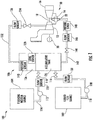
- FIG. 1 schematically illustrates a gas turbine system 10.
- the gas turbine system 10 may include a compressor 12, a combustor 14, and a turbine 16.
- the compressor 12 and turbine 16 may be coupled by a shaft 18.
- the shaft 18 may be a single shaft or a plurality of shaft segments coupled together to form shaft 18.
- the compressor 12 compresses air or another suitable working fluid flowing therethrough.
- the compressed working fluid flows to the combustor 14, where it is mixed with fuel and combusted to create high temperature and high pressure combustion gases.
- the combustion gases exit the combustor 14 and flow into the turbine 16, which extracts kinetic energy from the combustion gases to drive the shaft 18.
- rotation of the shaft 18 may drive the compressor 12, which compresses the working fluid.
- the shaft 18 may connect the turbine 16 to a generator 20 for producing electricity.
- the gas turbine 10 may be capable of operating on two or different types of fuels.
- the gas turbine 10 may be able to burn two or more of the following fuels: heavy fuel oils, naphtha, distillate, flare gas, syngas, landfill gas, and natural gas.
- the gas turbine 10 primarily operates on a gaseous fuel (e.g., natural gas), but also be able to burn a liquid fuel (e.g., diesel) when the gaseous fuel is unavailable.
- the gas turbine 10 may include a gaseous fuel manifold (not shown) and a liquid fuel manifold 22 for respectively supplying gaseous fuel and liquid fuel to the combustor 14.
- the primary fuel and the secondary fuel may be either gaseous or liquid.
- the gas turbine 10 may include a water injection manifold 24 for injecting water into the combustor 14 to maintain flame stability therein.
- FIG.1 also illustrates one embodiment of a system 100 for transitioning the gas turbine 10 from burning gaseous fuel to liquid fuel and purging the residual liquid fuel from the system 100 after transfer back to the gaseous fuel.
- the system 100 includes a liquid fuel source 102 and a flushing medium source 104 for respectively providing liquid fuel and a flushing medium (e.g., demineralized water) to an accumulator tank 106.
- the liquid fuel source 102 and the flushing medium source 104 are preferably tanks, but may be a pipe line or any other suitable source.
- a liquid fuel pump 108 pumps liquid fuel from the liquid fuel source 102 through a liquid fuel conduit 110 to the accumulator tank 106.
- a flushing medium pump 112 pumps flushing medium from the flushing medium source 104 through a flushing medium conduit 114 to the accumulator tank 106.
- a liquid fuel conduit valve 116 controls the flow of liquid fuel through the liquid fuel conduit 110
- a flushing medium conduit valve 118 controls the flow of flushing medium through the flushing medium conduit 114.
- the liquid fuel conduit 110 and the flushing medium conduit 114 may optionally include a liquid fuel conduit pressure sensor 120 and/or a flushing medium sensor 122, respectively.
- the accumulator tank 106 stores a volume of liquid 124 and a volume of motive gas 126 (e.g., pressurized air), which pressurizes the volume of liquid 124.
- the volume of motive gas 126 forces the volume of liquid 124 out of the accumulator tank 106.
- the volume of liquid 124 is alternately liquid fuel or flushing medium. That is, the volume of liquid 124 is either liquid fuel or flushing medium depending on the progress of the fuel transition, but not both at the same time.
- the flushing medium conduit valve 118 remains closed when the volume of liquid 124 is liquid fuel
- the liquid fuel conduit valve 116 remains closed when the volume of liquid 124 is flushing medium.
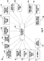
- the accumulator tank 106 may include an accumulator tank level sensor 128 for measuring the measuring the level or height of the volume of liquid 124 therein. As illustrated in FIG. 2 , the accumulator tank level sensor 128 communicates with a fuel transfer controller 130. In this respect, the fuel transfer controller 130 may modulate the liquid fuel pump 108, flushing medium pump 112, liquid fuel conduit valve 116, and flushing medium conduit valve 118 to maintain the proper level of the volume of liquid 124 in the accumulator tank 106 based on feedback from the accumulator tank level sensor 128 and, if included, the liquid fuel conduit and flushing medium conduit flow sensors 120, 122.
- the system 100 includes a motive gas conduit 132 for supplying motive gas to the accumulator tank 106.
- the motive gas conduit 132 includes a motive gas conduit valve 134 for controlling the flow of motive gas to the accumulator tank 106.
- the motive gas conduit 132 may include a motive gas conduit flow sensor 136.
- the motive gas flowing through the motive gas conduit 132 may be pressurized bled air from the compressor 12.
- an alternate embodiment of the system 100' may include a stand-alone motive gas pump 138 to provide pressurized air to the motive gas conduit 132.
- the stand-alone motive gas pump 136 is a separate and distinct component from the gas turbine 10.
- the accumulator tank 106 may include an accumulator tank pressure sensor 140 ( FIG. 1 ) for measuring the pressure of the volume of motive gas 126 therein. As illustrated in FIG. 2 , the accumulator tank pressure sensor 140 communicates with the fuel transfer controller 130. In this respect, the fuel transfer controller 130 may modulate the motive gas conduit valve 134 and/or the motive gas pump 138 to maintain the proper pressure of the volume of motive gas 126 in the accumulator tank 106 based on feedback from the accumulator tank pressure sensor 140 and, if included, the motive gas conduit flow sensor 136.
- the system 100 further includes a turbine conduit 142 for supplying the volume of liquid 124 (i.e., liquid fuel or flushing medium) to the gas turbine 10, and more specifically to the liquid fuel manifold 22, for combustion thereof.
- the turbine conduit 142 includes a turbine conduit valve 144, which controls the flow of the volume of liquid 124 into the turbine conduit 142. That is, the turbine conduit valve 144 permits the volume of liquid 124 to flow to the liquid fuel manifold 22 when open and prevents the volume of liquid 124 from flowing to the liquid fuel manifold 22 when closed.
- the turbine conduit 142 may optionally include a turbine conduit flow sensor 146 and/or a turbine conduit pressure sensor 148.
- the fuel transfer controller 130 communicates with a turbine controller 150, which controls the gas turbine 10.
- the turbine controller 150 monitors, inter alia, the pressure of the gaseous fuel supplied to the gas turbine 10. As long as the gaseous fuel pressure is sufficient and the transfer is not manually initiated, the fuel transfer controller 130 keeps the turbine conduit valve 144 closed. If the fuel transfer is manually initiated or the turbine controller 150 determines that the gaseous fuel pressure is too low or decaying at a predetermined rate due to the loss of gas compression, the fuel transfer controller 130 opens the turbine conduit valve 144, thereby permitting the volume of liquid 124 (in this case liquid fuel) to flow to the liquid fuel manifold 22. That is, the fuel source transfer may occur manually based on user input or automatically based on fuel pressure. In the embodiment illustrated in FIGS. 2 and 4 , the fuel transfer controller 130 and the turbine controller 150 are separate controllers. Although, the fuel transfer controller 130 may be integrated into the turbine controller 150.
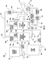
- a system 100" includes separate accumulator tanks for the liquid fuel and the flushing medium.
- the liquid fuel source 102 supplies liquid fuel to a liquid fuel accumulator tank 106a
- the flushing medium source 104 supplies flushing medium to a flushing medium accumulator tank 106b.
- the liquid fuel conduit 110 and the flushing medium conduit 114 respectively supply liquid fuel and flushing medium to the liquid fuel and flushing medium accumulator tanks 106a, 106b in the same manner as in systems 100, 100'.
- the liquid fuel accumulator tank 106a stores a volume of liquid fuel 124a and a first volume of motive gas 126a, which pressurizes the volume of liquid fuel 124a.
- the flushing medium accumulator tank 106b stores a volume of flushing medium 124b and a second volume of motive gas 126b, which pressurizes the volume of flushing medium 124b.
- the first and second volumes of motive gas 126a, 126b respectively force the volume of liquid fuel 124a and the volume of flushing medium 124b out of the liquid fuel and flushing medium accumulator tanks 106a, 106b.
- the liquid fuel and flushing medium accumulator tanks 106a, 106b may respectively include a liquid fuel accumulator tank level sensor 128a and a flushing medium accumulator tank level sensor 128b for respectively measuring the level or height of the volume of liquid fuel 124a and the volume of flushing medium 124b therein.
- the fuel transfer controller 130 may independently modulate the liquid fuel pump 108, flushing medium pump 112, liquid fuel conduit valve 116, and flushing medium conduit valve 118 to maintain the proper level of the volume of liquid fuel 124a and the volume of flushing medium 124b in the same manner as in system 100, 100'.
- the system 100" may supply motive gas to the liquid fuel and flushing medium accumulator tanks 106a, 106b through the motive gas conduit 132 in the same manner as in the systems 100, 100'.
- the motive gas conduit 132 splits into a liquid fuel accumulator tank branch 132a and a flushing medium accumulator tank branch 132b.
- the motive gas conduit valve 134 is upstream of the branches 132a, 132b.
- motive gas flows into the liquid fuel and flushing medium accumulator tanks 106a, 106b at the same time, in the same flow rate, and at the same pressure.
- the branches 132a, 132b may optionally include valves (not shown) for independently adjusting the timing, flow rate, or pressure of the motive gas delivered to the liquid fuel and flushing medium accumulator tanks 106a, 106b.
- the liquid fuel and flushing medium accumulator tanks 106a, 106b may respectively include a liquid fuel accumulator tank pressure sensor 140a and a flushing medium accumulator tank pressure sensor 140b for respectively measuring the pressure of the first and the second volumes of motive gas 126a, 126b therein.
- the fuel transfer controller 130 may independently modulate the motive gas conduit valve 134, the motive gas pump 138, and/or any other valves to maintain the proper pressure of the volume of motive gas 126 in the accumulator tank 106 in the same manner as in the systems 100, 100'.
- the turbine conduit 142 supplies the volume of liquid fuel 124a from the liquid fuel accumulator tank 106a to the liquid fuel manifold 22 for combustion thereof in the same manner as the systems 100, 100'.
- the turbine conduit 142 includes a check valve 152 disposed upstream of the turbine conduit valve 144. The check valve 152 prevents liquid in the turbine conduit 142 from flowing in the reverse direction back into the liquid fuel accumulator tank 106a.
- the system 100" further includes a flushing medium injection conduit 154 for supplying the volume of flushing medium 124b to the gas turbine 10, and more specifically to the water injection manifold 24.
- the flushing medium injection conduit 154 includes a flushing medium injection conduit valve 156, which controls the flow of the volume of flushing medium 124b exiting the flushing medium accumulator tank 106b.
- the flushing medium injection conduit 154 may optionally include a flushing medium injection conduit flow sensor 158 and/or a flushing medium injection conduit pressure sensor 160.
- a transfer conduit 162 fluidly couples the turbine conduit 142 and the flushing medium injection conduit 154.
- the transfer conduit 162 permits at least a portion of the volume of flushing medium 124b to flow into the turbine conduit 142 to the liquid fuel manifold 22.
- the transfer conduit 162 connects to the turbine conduit 142 downstream of the check valve 152 and upstream of the turbine conduit valve 144.
- the check valve 152 prevents the flushing medium from flowing into the liquid fuel accumulator tank 106a, and the turbine conduit valve 144 controls the flow of flushing medium to the liquid fuel manifold 22.
- the transfer conduit 162 connects to a three-way valve 164 disposed in the flushing medium injection conduit 154 downstream of the flushing medium injection conduit valve 156.
- the three-way valve 164 controls the destination of the volume of flushing medium 124b leaving the flushing medium accumulator tank 106b. More specifically, the three-way valve 164 directs the volume of flushing medium 124b to the water injection manifold 24 by blocking access to the transfer conduit 162. Analogously, the three-way valve 164 directs the volume of flushing medium 124b to the liquid fuel manifold 22 by opening access to the transfer conduit 162 and blocking access to the portion of the flushing medium injection conduit 154 downstream of the three-way valve 164. As illustrated in FIG. 6 , the fuel transfer controller 130 may control the operation of the three-way valve 164.
- the liquid fuel conduit valve 116, the flushing medium conduit valve 118, the motive gas conduit valve 134, the turbine conduit valve 144, and flushing medium injection conduit valve 154 may be globe valves, gate valves, butterfly valves, ball valves, or any other type of valve.
- the three-way valve 164 may be an electrically controlled solenoid valve or any other type of three-way valve.
- the valves 116, 118, 134, 144, 154, 164 in the systems 100, 100', 100" may be electrically controlled via the fuel transfer controller 130 or the turbine controller 150. Alternately, the valves 116, 118, 134, 144, 154, 164 may be manually controlled.
- the fuel transfer controller 130 may comprise any combination of microprocessors, circuitry, or other programmed logic circuit and is not limited to any particular hardware architecture or configuration. Embodiments of the systems and methods set forth herein may be implemented by one or more general-purpose or customized controllers 130 adapted in any suitable manner to provide the desired functionality.
- the controller 130 may be adapted to provide additional functionality, either complementary or unrelated to the present subject matter.
- one or more controllers 130 may be adapted to provide the described functionality by accessing software instructions rendered in a computer-readable form.
- any suitable programming, scripting, or other type of language or combinations of languages may be used to implement the teachings contained herein. Nevertheless, software need not be used exclusively, or at all.
- FIG. 7 is a flowchart illustrating an exemplary method (200) for transitioning the gas turbine 10 from burning gaseous fuel to liquid fuel and purging the liquid fuel from the systems 100, 100', 100" after transfer back to the gaseous fuel.
- the volume of motive gas 126, 126a pressurizes the volume of liquid fuel 124a in the accumulator tank 106 ( FIGS. 1 and 3 ) or liquid fuel accumulator tank 106a ( FIG. 5 ).
- the liquid fuel pump 108 may pump a volume of liquid fuel 124a from the liquid fuel source 102 into the accumulator tank 106 ( FIGS. 1 and 3 ) or liquid fuel accumulator tank 106a ( FIG. 5 ).
- the accumulator tank level sensor 128 (FIGS. land 3) or the liquid fuel accumulator tank level sensor 128a ( FIG. 5 ) may provide feedback to the fuel transfer controller 130, which modulates the liquid fuel pump 108 as needed to reach the desired level of the volume of liquid fuel 124a.
- the controller 130 may also modulate the motive gas conduit valve 134 and, if present, the motive gas pump 138 in response to feedback from the accumulator tank pressure sensor 140 ( FIGS. 1 and 3 ) or liquid fuel accumulator tank pressure sensor 140a ( FIG. 5 ) to maintain the desired pressure in the accumulator tank 106 ( FIGS. 1 and 3 ) or the liquid fuel accumulator tank 106a ( FIG. 5 ).
- the fuel transfer controller 130 opens the turbine conduit valve 144 in response to a manual signal to transfer fuel sources or low gaseous fuel pressure in the fuel supply system of the gas turbine 10.
- the fuel transfer controller 130 is communication with the turbine controller 150, which preferably monitors gaseous fuel pressure.
- the pressure in the accumulator tank 106 ( FIGS. 1 and 3 ) or the liquid fuel accumulator tank 106a ( FIG. 5 ) created by the volume of motive gas 126, 126a forces the volume of liquid fuel 124a through the turbine conduit 142 for eventual delivery to the liquid manifold 22.
- the fuel transfer controller 130 closes the turbine conduit valve 144.
- the fuel transfer controller 130 may optionally open the flushing medium injection conduit valve 156 if the flushing medium accumulator tank 106b has been filled with the volume of flushing medium 124b in accordance with step (206), discussed below.
- the flushing medium injection conduit valve 156 permits a portion of the volume of the flushing medium 124b to flow to the water injection manifold 24. This may be advantageous when the flushing medium, e.g., demineralized water, is used for flame stabilization in the combustor 14.
- the three-way valve 164 should be positioned to block flow to the transfer conduit 162. After delivery of the volume of liquid fuel 124a to the liquid fuel manifold 22, the fuel transfer controller 130 switches the position of the three-way valve 164 to open the transfer conduit 162 and block the downstream portion of the flushing medium injection conduit 154.
- step (206) the volume of motive gas 126, 126b pressurizes the volume of flushing medium 124b in the accumulator tank 106 ( FIGS. 1 and 3 ) or flushing medium accumulator tank 106b ( FIG. 5 ).
- the flushing medium pump 112 may pump the volume of flushing medium 124b from the flushing medium source 104 into the accumulator tank 106 ( FIGS. 1 and 3 ) or flushing medium accumulator tank 106b ( FIG. 5 ).
- the accumulator tank level sensor 128 FIGS. land 3) or the flushing medium accumulator tank level sensor 128b ( FIG.
- step (206) may be done before, during, or after step (202).
- step (208) at least a portion of the volume of flushing medium 124b flows through the turbine conduit 142 after the entire volume of liquid fuel was burned, thereby flushing any residual liquid fuel therefrom.
- the step (208) may occur after the gas turbine 10 has switched back to operating the primary fuel.
- the fuel transfer controller 130 opens the turbine conduit valve 144.
- the pressure in the accumulator tank 106 created by the volume of motive gas 126 forces the volume of flushing medium 124b through the turbine conduit 142 for eventual delivery to the liquid manifold 22.
- any residual liquid fuel is flushed from the turbine conduit 142.
- the fuel transfer controller 130 closes the turbine conduit valve 144.
- the fuel transfer controller 130 opens the flushing medium injection conduit valve 156.
- the pressure in the flushing medium accumulator tank 106b created by the volume of motive gas 126b forces the volume of flushing medium 124b into the flushing medium injection conduit 142.
- the three-way valve 164 directs the volume of flushing medium 124b in the transfer conduit 162, which directs the volume of flushing medium 124b to the turbine conduit 142. In this respect, any residual liquid fuel is flushed from the turbine conduit 142.
- the fuel transfer controller 130 closes the flushing medium injection conduit valve 156.
- the liquid fuel pump 108 may pump another volume of liquid fuel 124a from the liquid fuel source 102 into the accumulator tank 106 ( FIGS. 1 and 3 ) or liquid fuel accumulator tank 106a ( FIG. 5 ). Motive gas may then pressurize the volume of liquid fuel 124a.
- the flushing medium pump 112 may pump another volume of flushing medium 124b from the flushing medium source 104 into the flushing medium accumulator tank 106b. Motive gas may then pressurize the volume of flushing medium 124b.
- the systems 100, 100', 100" and the method (200) permits the gas turbine 10 to switch from a gaseous fuel (e.g., natural gas) to a liquid fuel (e.g., diesel) without requiring shut down thereof.
- a gaseous fuel e.g., natural gas
- a liquid fuel e.g., diesel
- power plant availability and capacity are improved.
- the systems 100, 100', 100" and the method (200) purge any residual liquid fuel therefrom to prevent coke deposits from forming, thereby improving reliability and reducing failed fuel transfers. In fact, all valves and other components that supply liquid fuel to the gas turbine 10 are flushed.
- the systems 100, 100', 100" and the method (200) are easily implementable on existing gas turbines.
Landscapes
- Engineering & Computer Science (AREA)
- Chemical & Material Sciences (AREA)
- Combustion & Propulsion (AREA)
- Mechanical Engineering (AREA)
- General Engineering & Computer Science (AREA)
- Engine Equipment That Uses Special Cycles (AREA)
Applications Claiming Priority (1)
| Application Number | Priority Date | Filing Date | Title |
|---|---|---|---|
| US14/862,374 US10247110B2 (en) | 2015-09-23 | 2015-09-23 | Method and system for reliable gas to liquid transfer |
Publications (2)
| Publication Number | Publication Date |
|---|---|
| EP3147484A1 EP3147484A1 (en) | 2017-03-29 |
| EP3147484B1 true EP3147484B1 (en) | 2019-01-02 |
Family
ID=57218668
Family Applications (1)
| Application Number | Title | Priority Date | Filing Date |
|---|---|---|---|
| EP16190181.4A Active EP3147484B1 (en) | 2015-09-23 | 2016-09-22 | Method and system for reliable gas to liquid transfer |
Country Status (4)
| Country | Link |
|---|---|
| US (1) | US10247110B2 (https=) |
| EP (1) | EP3147484B1 (https=) |
| JP (1) | JP6877925B2 (https=) |
| CN (1) | CN106988890B (https=) |
Families Citing this family (7)
| Publication number | Priority date | Publication date | Assignee | Title |
|---|---|---|---|---|
| DE102014212824A1 (de) * | 2014-07-02 | 2016-01-07 | Siemens Aktiengesellschaft | Verfahren und Vorrichtung zum Spülen und/oder Sperren wenigstens eines Brenners einer Gasturbinenanlage |
| US11555456B2 (en) | 2019-07-24 | 2023-01-17 | Pratt & Whitney Canada Corp. | Fuel delivery system and method |
| FR3126025B1 (fr) * | 2021-08-03 | 2025-02-14 | Safran | Système de conditionnement de carburant pour alimenter une turbomachine d’aéronef, aéronef et procédé d’utilisation |
| EP4163481B1 (en) * | 2021-09-17 | 2023-11-01 | Rolls-Royce plc | Fuel delivery system |
| US11898491B1 (en) * | 2022-07-21 | 2024-02-13 | Rtx Corporation | Water pressure and quantity monitoring for hydrogen steam injected and inter-cooled turbine engine |
| US12535039B2 (en) | 2024-01-11 | 2026-01-27 | General Electric Company | Methods and apparatus to regulate a gaseous fuel system |
| WO2025264222A1 (en) * | 2024-06-20 | 2025-12-26 | Ge Vernova Infrastructure Technology Llc | Fuel flush system and method |
Family Cites Families (22)
| Publication number | Priority date | Publication date | Assignee | Title |
|---|---|---|---|---|
| GB719996A (en) | 1951-11-24 | 1954-12-08 | Gen Electric | Improvements in and relating to dual liquid fuel systems |
| US3878678A (en) * | 1973-08-20 | 1975-04-22 | Gen Motors Corp | Gas turbine fuel system |
| FR2501290B1 (fr) * | 1981-03-06 | 1985-11-08 | Snecma | Limiteur d'acceleration pour turbomachine |
| JPS6329029A (ja) * | 1986-07-23 | 1988-02-06 | Hitachi Ltd | ガスタ−ビンの運転方法 |
| US5490387A (en) * | 1994-05-25 | 1996-02-13 | Coltec Industries Inc | Flame-out resistant fuel pumping system |
| DE19647492A1 (de) * | 1996-11-16 | 1998-05-20 | Abb Research Ltd | Verfahren und Vorrichtung zur Speisung einer Gasturbine sowohl mit flüssigen wie auch mit gasförmigen Brennstoffen |
| DE59810159D1 (de) * | 1998-02-26 | 2003-12-18 | Alstom Switzerland Ltd | Verfahren zum sicheren Entfernen von Flüssigbrennstoff aus dem Brennstoffsystem einer Gasturbine sowie Vorrichtung zur Durchführung des Verfahrens |
| EP1199453A3 (en) | 1998-05-08 | 2003-01-22 | Mitsubishi Heavy Industries, Ltd. | Gas turbine fuel nozzle wash system |
| EP1730445B1 (de) * | 2004-03-31 | 2009-05-13 | Alstom Technology Ltd | Verfahren zum Betreiben einer Wärmekraftmaschine, Vorzugsweise einer Gasturbinenanlage |
| US7340939B2 (en) * | 2004-08-25 | 2008-03-11 | Jansen's Aircraft Systems Controls, Inc. | Emissions sampling valve |
| JP4775643B2 (ja) * | 2006-06-06 | 2011-09-21 | 株式会社Ihi | ガスタービンの燃料切替装置及び方法 |
| US7681401B2 (en) | 2006-08-24 | 2010-03-23 | General Electric Company | Methods and systems for operating a gas turbine |
| JP2008136929A (ja) | 2006-12-01 | 2008-06-19 | Mitsubishi Heavy Ind Ltd | ノズル洗浄装置 |
| US20090165435A1 (en) * | 2008-01-02 | 2009-07-02 | Michal Koranek | Dual fuel can combustor with automatic liquid fuel purge |
| US8783007B2 (en) * | 2010-05-04 | 2014-07-22 | General Electric Company | Liquid fuel system and method |
| US9103285B2 (en) * | 2011-01-03 | 2015-08-11 | General Electric Company | Purge system, system including a purge system, and purge method |
| US9650955B2 (en) * | 2011-11-10 | 2017-05-16 | General Electric Company | System for purging gas fuel circuit for a gas turbine engine |
| US20130199576A1 (en) * | 2012-02-06 | 2013-08-08 | General Electric Company | System and method to clear a liquid fuel supply line |
| FI123618B (en) * | 2012-05-11 | 2013-08-15 | Waertsilae Finland Oy | A method for operating a dual fuel engine |
| US10156192B2 (en) * | 2012-10-05 | 2018-12-18 | General Electric Company | Gas turbine engine with a multiple fuel delivery system |
| US9718075B2 (en) * | 2014-06-12 | 2017-08-01 | United Technologies Corporation | Suspension plasma injector system and method of flushing the system |
| FR3030629B1 (fr) * | 2014-12-23 | 2017-02-03 | Ge Energy Products France Snc | Installation et procede d'alimentation d'une chambre de combustion ayant une cavite ventilee par air chaud de purge |
-
2015
- 2015-09-23 US US14/862,374 patent/US10247110B2/en active Active
-
2016
- 2016-09-13 JP JP2016178123A patent/JP6877925B2/ja active Active
- 2016-09-22 EP EP16190181.4A patent/EP3147484B1/en active Active
- 2016-09-23 CN CN201610843646.5A patent/CN106988890B/zh active Active
Non-Patent Citations (1)
| Title |
|---|
| None * |
Also Published As
| Publication number | Publication date |
|---|---|
| JP6877925B2 (ja) | 2021-05-26 |
| CN106988890B (zh) | 2020-10-27 |
| US20170082034A1 (en) | 2017-03-23 |
| US10247110B2 (en) | 2019-04-02 |
| CN106988890A (zh) | 2017-07-28 |
| EP3147484A1 (en) | 2017-03-29 |
| JP2017061928A (ja) | 2017-03-30 |
Similar Documents
| Publication | Publication Date | Title |
|---|---|---|
| EP3147484B1 (en) | Method and system for reliable gas to liquid transfer | |
| CN101210519B (zh) | 用于燃气涡轮机的非线性燃料转换 | |
| CN1963159B (zh) | 用于燃气轮机氮气清洗系统的方法和设备 | |
| JP2017061928A5 (https=) | ||
| US9188061B2 (en) | System for turbine combustor fuel assembly | |
| CN106062315B (zh) | 具有用于改进的燃料管线冲刷的旁通管线的燃气轮机以及用于冲刷燃气轮机的方法 | |
| JP4246874B2 (ja) | 多機能付加型水噴射マニホールド及びその操作方法 | |
| CN112727604A (zh) | 用于燃气轮机的液体/气体双燃料供应系统 | |
| US8783007B2 (en) | Liquid fuel system and method | |
| JP2002161757A (ja) | 燃焼器エミッションの低減方法及び装置 | |
| JP2011522990A (ja) | ガスタービンの燃料系統を洗浄する方法とその燃料系統 | |
| CN102308066A (zh) | 用于冲洗燃气轮机的燃料系统的部段的方法 | |
| EP4234905B1 (en) | Method for providing highly reactive fuels to a combustor | |
| JP2001263092A (ja) | ガスタービン | |
| EP2623740B1 (en) | Method for transferring fuel | |
| CN103291460A (zh) | 用于涡轮机总成的燃料净化系统 | |
| EP2379944B1 (en) | Method for supplying a gas turbine plant and gas turbine plant | |
| CN103307632B (zh) | 对燃烧器进行操作以从液体燃料操作转换到气体燃料操作的方法 | |
| CN114837823B (zh) | 一种基于双燃料控制系统的燃气轮机启动逻辑方法 | |
| CN106168383A (zh) | 燃气涡轮发动机液体燃料供给系统和方法 | |
| CN114810358A (zh) | 燃气轮机低排放双燃料系统及其控制方法 | |
| JP4198107B2 (ja) | ガンタイプオイルバーナ装置 | |
| EP3517759A1 (en) | Gas turbine plant and method for operating a gas turbine plant |
Legal Events
| Date | Code | Title | Description |
|---|---|---|---|
| PUAI | Public reference made under article 153(3) epc to a published international application that has entered the european phase |
Free format text: ORIGINAL CODE: 0009012 |
|
| STAA | Information on the status of an ep patent application or granted ep patent |
Free format text: STATUS: THE APPLICATION HAS BEEN PUBLISHED |
|
| AK | Designated contracting states |
Kind code of ref document: A1 Designated state(s): AL AT BE BG CH CY CZ DE DK EE ES FI FR GB GR HR HU IE IS IT LI LT LU LV MC MK MT NL NO PL PT RO RS SE SI SK SM TR |
|
| AX | Request for extension of the european patent |
Extension state: BA ME |
|
| STAA | Information on the status of an ep patent application or granted ep patent |
Free format text: STATUS: REQUEST FOR EXAMINATION WAS MADE |
|
| 17P | Request for examination filed |
Effective date: 20170929 |
|
| RBV | Designated contracting states (corrected) |
Designated state(s): AL AT BE BG CH CY CZ DE DK EE ES FI FR GB GR HR HU IE IS IT LI LT LU LV MC MK MT NL NO PL PT RO RS SE SI SK SM TR |
|
| GRAP | Despatch of communication of intention to grant a patent |
Free format text: ORIGINAL CODE: EPIDOSNIGR1 |
|
| STAA | Information on the status of an ep patent application or granted ep patent |
Free format text: STATUS: GRANT OF PATENT IS INTENDED |
|
| INTG | Intention to grant announced |
Effective date: 20180802 |
|
| GRAS | Grant fee paid |
Free format text: ORIGINAL CODE: EPIDOSNIGR3 |
|
| GRAA | (expected) grant |
Free format text: ORIGINAL CODE: 0009210 |
|
| STAA | Information on the status of an ep patent application or granted ep patent |
Free format text: STATUS: THE PATENT HAS BEEN GRANTED |
|
| AK | Designated contracting states |
Kind code of ref document: B1 Designated state(s): AL AT BE BG CH CY CZ DE DK EE ES FI FR GB GR HR HU IE IS IT LI LT LU LV MC MK MT NL NO PL PT RO RS SE SI SK SM TR |
|
| REG | Reference to a national code |
Ref country code: GB Ref legal event code: FG4D |
|
| REG | Reference to a national code |
Ref country code: CH Ref legal event code: EP Ref country code: AT Ref legal event code: REF Ref document number: 1084683 Country of ref document: AT Kind code of ref document: T Effective date: 20190115 |
|
| REG | Reference to a national code |
Ref country code: IE Ref legal event code: FG4D |
|
| REG | Reference to a national code |
Ref country code: DE Ref legal event code: R096 Ref document number: 602016008899 Country of ref document: DE |
|
| REG | Reference to a national code |
Ref country code: NL Ref legal event code: MP Effective date: 20190102 |
|
| REG | Reference to a national code |
Ref country code: LT Ref legal event code: MG4D |
|
| REG | Reference to a national code |
Ref country code: AT Ref legal event code: MK05 Ref document number: 1084683 Country of ref document: AT Kind code of ref document: T Effective date: 20190102 |
|
| PG25 | Lapsed in a contracting state [announced via postgrant information from national office to epo] |
Ref country code: NL Free format text: LAPSE BECAUSE OF FAILURE TO SUBMIT A TRANSLATION OF THE DESCRIPTION OR TO PAY THE FEE WITHIN THE PRESCRIBED TIME-LIMIT Effective date: 20190102 |
|
| PG25 | Lapsed in a contracting state [announced via postgrant information from national office to epo] |
Ref country code: ES Free format text: LAPSE BECAUSE OF FAILURE TO SUBMIT A TRANSLATION OF THE DESCRIPTION OR TO PAY THE FEE WITHIN THE PRESCRIBED TIME-LIMIT Effective date: 20190102 Ref country code: SE Free format text: LAPSE BECAUSE OF FAILURE TO SUBMIT A TRANSLATION OF THE DESCRIPTION OR TO PAY THE FEE WITHIN THE PRESCRIBED TIME-LIMIT Effective date: 20190102 Ref country code: PT Free format text: LAPSE BECAUSE OF FAILURE TO SUBMIT A TRANSLATION OF THE DESCRIPTION OR TO PAY THE FEE WITHIN THE PRESCRIBED TIME-LIMIT Effective date: 20190502 Ref country code: NO Free format text: LAPSE BECAUSE OF FAILURE TO SUBMIT A TRANSLATION OF THE DESCRIPTION OR TO PAY THE FEE WITHIN THE PRESCRIBED TIME-LIMIT Effective date: 20190402 Ref country code: LT Free format text: LAPSE BECAUSE OF FAILURE TO SUBMIT A TRANSLATION OF THE DESCRIPTION OR TO PAY THE FEE WITHIN THE PRESCRIBED TIME-LIMIT Effective date: 20190102 Ref country code: PL Free format text: LAPSE BECAUSE OF FAILURE TO SUBMIT A TRANSLATION OF THE DESCRIPTION OR TO PAY THE FEE WITHIN THE PRESCRIBED TIME-LIMIT Effective date: 20190102 Ref country code: FI Free format text: LAPSE BECAUSE OF FAILURE TO SUBMIT A TRANSLATION OF THE DESCRIPTION OR TO PAY THE FEE WITHIN THE PRESCRIBED TIME-LIMIT Effective date: 20190102 |
|
| PG25 | Lapsed in a contracting state [announced via postgrant information from national office to epo] |
Ref country code: BG Free format text: LAPSE BECAUSE OF FAILURE TO SUBMIT A TRANSLATION OF THE DESCRIPTION OR TO PAY THE FEE WITHIN THE PRESCRIBED TIME-LIMIT Effective date: 20190402 Ref country code: RS Free format text: LAPSE BECAUSE OF FAILURE TO SUBMIT A TRANSLATION OF THE DESCRIPTION OR TO PAY THE FEE WITHIN THE PRESCRIBED TIME-LIMIT Effective date: 20190102 Ref country code: IS Free format text: LAPSE BECAUSE OF FAILURE TO SUBMIT A TRANSLATION OF THE DESCRIPTION OR TO PAY THE FEE WITHIN THE PRESCRIBED TIME-LIMIT Effective date: 20190502 Ref country code: LV Free format text: LAPSE BECAUSE OF FAILURE TO SUBMIT A TRANSLATION OF THE DESCRIPTION OR TO PAY THE FEE WITHIN THE PRESCRIBED TIME-LIMIT Effective date: 20190102 Ref country code: HR Free format text: LAPSE BECAUSE OF FAILURE TO SUBMIT A TRANSLATION OF THE DESCRIPTION OR TO PAY THE FEE WITHIN THE PRESCRIBED TIME-LIMIT Effective date: 20190102 Ref country code: GR Free format text: LAPSE BECAUSE OF FAILURE TO SUBMIT A TRANSLATION OF THE DESCRIPTION OR TO PAY THE FEE WITHIN THE PRESCRIBED TIME-LIMIT Effective date: 20190403 |
|
| REG | Reference to a national code |
Ref country code: DE Ref legal event code: R097 Ref document number: 602016008899 Country of ref document: DE |
|
| PG25 | Lapsed in a contracting state [announced via postgrant information from national office to epo] |
Ref country code: SK Free format text: LAPSE BECAUSE OF FAILURE TO SUBMIT A TRANSLATION OF THE DESCRIPTION OR TO PAY THE FEE WITHIN THE PRESCRIBED TIME-LIMIT Effective date: 20190102 Ref country code: EE Free format text: LAPSE BECAUSE OF FAILURE TO SUBMIT A TRANSLATION OF THE DESCRIPTION OR TO PAY THE FEE WITHIN THE PRESCRIBED TIME-LIMIT Effective date: 20190102 Ref country code: DK Free format text: LAPSE BECAUSE OF FAILURE TO SUBMIT A TRANSLATION OF THE DESCRIPTION OR TO PAY THE FEE WITHIN THE PRESCRIBED TIME-LIMIT Effective date: 20190102 Ref country code: AL Free format text: LAPSE BECAUSE OF FAILURE TO SUBMIT A TRANSLATION OF THE DESCRIPTION OR TO PAY THE FEE WITHIN THE PRESCRIBED TIME-LIMIT Effective date: 20190102 Ref country code: AT Free format text: LAPSE BECAUSE OF FAILURE TO SUBMIT A TRANSLATION OF THE DESCRIPTION OR TO PAY THE FEE WITHIN THE PRESCRIBED TIME-LIMIT Effective date: 20190102 Ref country code: CZ Free format text: LAPSE BECAUSE OF FAILURE TO SUBMIT A TRANSLATION OF THE DESCRIPTION OR TO PAY THE FEE WITHIN THE PRESCRIBED TIME-LIMIT Effective date: 20190102 Ref country code: RO Free format text: LAPSE BECAUSE OF FAILURE TO SUBMIT A TRANSLATION OF THE DESCRIPTION OR TO PAY THE FEE WITHIN THE PRESCRIBED TIME-LIMIT Effective date: 20190102 |
|
| PGFP | Annual fee paid to national office [announced via postgrant information from national office to epo] |
Ref country code: IT Payment date: 20190930 Year of fee payment: 4 |
|
| PLBE | No opposition filed within time limit |
Free format text: ORIGINAL CODE: 0009261 |
|
| STAA | Information on the status of an ep patent application or granted ep patent |
Free format text: STATUS: NO OPPOSITION FILED WITHIN TIME LIMIT |
|
| PG25 | Lapsed in a contracting state [announced via postgrant information from national office to epo] |
Ref country code: SM Free format text: LAPSE BECAUSE OF FAILURE TO SUBMIT A TRANSLATION OF THE DESCRIPTION OR TO PAY THE FEE WITHIN THE PRESCRIBED TIME-LIMIT Effective date: 20190102 |
|
| 26N | No opposition filed |
Effective date: 20191003 |
|
| PG25 | Lapsed in a contracting state [announced via postgrant information from national office to epo] |
Ref country code: SI Free format text: LAPSE BECAUSE OF FAILURE TO SUBMIT A TRANSLATION OF THE DESCRIPTION OR TO PAY THE FEE WITHIN THE PRESCRIBED TIME-LIMIT Effective date: 20190102 |
|
| PG25 | Lapsed in a contracting state [announced via postgrant information from national office to epo] |
Ref country code: TR Free format text: LAPSE BECAUSE OF FAILURE TO SUBMIT A TRANSLATION OF THE DESCRIPTION OR TO PAY THE FEE WITHIN THE PRESCRIBED TIME-LIMIT Effective date: 20190102 |
|
| PG25 | Lapsed in a contracting state [announced via postgrant information from national office to epo] |
Ref country code: MC Free format text: LAPSE BECAUSE OF FAILURE TO SUBMIT A TRANSLATION OF THE DESCRIPTION OR TO PAY THE FEE WITHIN THE PRESCRIBED TIME-LIMIT Effective date: 20190102 |
|
| REG | Reference to a national code |
Ref country code: CH Ref legal event code: PL |
|
| PG25 | Lapsed in a contracting state [announced via postgrant information from national office to epo] |
Ref country code: IE Free format text: LAPSE BECAUSE OF NON-PAYMENT OF DUE FEES Effective date: 20190922 Ref country code: LU Free format text: LAPSE BECAUSE OF NON-PAYMENT OF DUE FEES Effective date: 20190922 Ref country code: LI Free format text: LAPSE BECAUSE OF NON-PAYMENT OF DUE FEES Effective date: 20190930 Ref country code: CH Free format text: LAPSE BECAUSE OF NON-PAYMENT OF DUE FEES Effective date: 20190930 |
|
| REG | Reference to a national code |
Ref country code: BE Ref legal event code: MM Effective date: 20190930 |
|
| PG25 | Lapsed in a contracting state [announced via postgrant information from national office to epo] |
Ref country code: BE Free format text: LAPSE BECAUSE OF NON-PAYMENT OF DUE FEES Effective date: 20190930 |
|
| PG25 | Lapsed in a contracting state [announced via postgrant information from national office to epo] |
Ref country code: FR Free format text: LAPSE BECAUSE OF NON-PAYMENT OF DUE FEES Effective date: 20190930 |
|
| GBPC | Gb: european patent ceased through non-payment of renewal fee |
Effective date: 20200922 |
|
| PG25 | Lapsed in a contracting state [announced via postgrant information from national office to epo] |
Ref country code: CY Free format text: LAPSE BECAUSE OF FAILURE TO SUBMIT A TRANSLATION OF THE DESCRIPTION OR TO PAY THE FEE WITHIN THE PRESCRIBED TIME-LIMIT Effective date: 20190102 |
|
| PG25 | Lapsed in a contracting state [announced via postgrant information from national office to epo] |
Ref country code: HU Free format text: LAPSE BECAUSE OF FAILURE TO SUBMIT A TRANSLATION OF THE DESCRIPTION OR TO PAY THE FEE WITHIN THE PRESCRIBED TIME-LIMIT; INVALID AB INITIO Effective date: 20160922 Ref country code: MT Free format text: LAPSE BECAUSE OF FAILURE TO SUBMIT A TRANSLATION OF THE DESCRIPTION OR TO PAY THE FEE WITHIN THE PRESCRIBED TIME-LIMIT Effective date: 20190102 |
|
| PG25 | Lapsed in a contracting state [announced via postgrant information from national office to epo] |
Ref country code: GB Free format text: LAPSE BECAUSE OF NON-PAYMENT OF DUE FEES Effective date: 20200922 |
|
| PG25 | Lapsed in a contracting state [announced via postgrant information from national office to epo] |
Ref country code: IT Free format text: LAPSE BECAUSE OF NON-PAYMENT OF DUE FEES Effective date: 20200922 |
|
| PG25 | Lapsed in a contracting state [announced via postgrant information from national office to epo] |
Ref country code: MK Free format text: LAPSE BECAUSE OF FAILURE TO SUBMIT A TRANSLATION OF THE DESCRIPTION OR TO PAY THE FEE WITHIN THE PRESCRIBED TIME-LIMIT Effective date: 20190102 |
|
| REG | Reference to a national code |
Ref country code: DE Ref legal event code: R081 Ref document number: 602016008899 Country of ref document: DE Owner name: GENERAL ELECTRIC TECHNOLOGY GMBH, CH Free format text: FORMER OWNER: GENERAL ELECTRIC CO., SCHENECTADY, N.Y., US |
|
| PGFP | Annual fee paid to national office [announced via postgrant information from national office to epo] |
Ref country code: DE Payment date: 20240820 Year of fee payment: 9 |