EP3147223B1 - Ensemble deployable - Google Patents
Ensemble deployable Download PDFInfo
- Publication number
- EP3147223B1 EP3147223B1 EP16188438.2A EP16188438A EP3147223B1 EP 3147223 B1 EP3147223 B1 EP 3147223B1 EP 16188438 A EP16188438 A EP 16188438A EP 3147223 B1 EP3147223 B1 EP 3147223B1
- Authority
- EP
- European Patent Office
- Prior art keywords
- panels
- rotation
- assembly
- satellite
- main axis
- Prior art date
- Legal status (The legal status is an assumption and is not a legal conclusion. Google has not performed a legal analysis and makes no representation as to the accuracy of the status listed.)
- Active
Links
Images



Classifications
-
- H—ELECTRICITY
- H02—GENERATION; CONVERSION OR DISTRIBUTION OF ELECTRIC POWER
- H02S—GENERATION OF ELECTRIC POWER BY CONVERSION OF INFRARED RADIATION, VISIBLE LIGHT OR ULTRAVIOLET LIGHT, e.g. USING PHOTOVOLTAIC [PV] MODULES
- H02S20/00—Supporting structures for PV modules
- H02S20/30—Supporting structures being movable or adjustable, e.g. for angle adjustment
-
- B—PERFORMING OPERATIONS; TRANSPORTING
- B64—AIRCRAFT; AVIATION; COSMONAUTICS
- B64G—COSMONAUTICS; VEHICLES OR EQUIPMENT THEREFOR
- B64G1/00—Cosmonautic vehicles
- B64G1/10—Artificial satellites; Systems of such satellites; Interplanetary vehicles
-
- B—PERFORMING OPERATIONS; TRANSPORTING
- B64—AIRCRAFT; AVIATION; COSMONAUTICS
- B64G—COSMONAUTICS; VEHICLES OR EQUIPMENT THEREFOR
- B64G1/00—Cosmonautic vehicles
- B64G1/22—Parts of, or equipment specially adapted for fitting in or to, cosmonautic vehicles
- B64G1/222—Parts of, or equipment specially adapted for fitting in or to, cosmonautic vehicles for deploying structures between a stowed and deployed state
- B64G1/2221—Parts of, or equipment specially adapted for fitting in or to, cosmonautic vehicles for deploying structures between a stowed and deployed state characterised by the manner of deployment
- B64G1/2222—Folding
- B64G1/2224—Folding about multiple axes
-
- B—PERFORMING OPERATIONS; TRANSPORTING
- B64—AIRCRAFT; AVIATION; COSMONAUTICS
- B64G—COSMONAUTICS; VEHICLES OR EQUIPMENT THEREFOR
- B64G1/00—Cosmonautic vehicles
- B64G1/22—Parts of, or equipment specially adapted for fitting in or to, cosmonautic vehicles
- B64G1/42—Arrangements or adaptations of power supply systems
- B64G1/44—Arrangements or adaptations of power supply systems using radiation, e.g. deployable solar arrays
-
- B—PERFORMING OPERATIONS; TRANSPORTING
- B64—AIRCRAFT; AVIATION; COSMONAUTICS
- B64G—COSMONAUTICS; VEHICLES OR EQUIPMENT THEREFOR
- B64G1/00—Cosmonautic vehicles
- B64G1/22—Parts of, or equipment specially adapted for fitting in or to, cosmonautic vehicles
- B64G1/42—Arrangements or adaptations of power supply systems
- B64G1/44—Arrangements or adaptations of power supply systems using radiation, e.g. deployable solar arrays
- B64G1/443—Photovoltaic cell arrays
-
- H—ELECTRICITY
- H02—GENERATION; CONVERSION OR DISTRIBUTION OF ELECTRIC POWER
- H02S—GENERATION OF ELECTRIC POWER BY CONVERSION OF INFRARED RADIATION, VISIBLE LIGHT OR ULTRAVIOLET LIGHT, e.g. USING PHOTOVOLTAIC [PV] MODULES
- H02S30/00—Structural details of PV modules other than those related to light conversion
-
- H—ELECTRICITY
- H10—SEMICONDUCTOR DEVICES; ELECTRIC SOLID-STATE DEVICES NOT OTHERWISE PROVIDED FOR
- H10F—INORGANIC SEMICONDUCTOR DEVICES SENSITIVE TO INFRARED RADIATION, LIGHT, ELECTROMAGNETIC RADIATION OF SHORTER WAVELENGTH OR CORPUSCULAR RADIATION
- H10F19/00—Integrated devices, or assemblies of multiple devices, comprising at least one photovoltaic cell covered by group H10F10/00, e.g. photovoltaic modules
- H10F19/90—Structures for connecting between photovoltaic cells, e.g. interconnections or insulating spacers
-
- Y—GENERAL TAGGING OF NEW TECHNOLOGICAL DEVELOPMENTS; GENERAL TAGGING OF CROSS-SECTIONAL TECHNOLOGIES SPANNING OVER SEVERAL SECTIONS OF THE IPC; TECHNICAL SUBJECTS COVERED BY FORMER USPC CROSS-REFERENCE ART COLLECTIONS [XRACs] AND DIGESTS
- Y02—TECHNOLOGIES OR APPLICATIONS FOR MITIGATION OR ADAPTATION AGAINST CLIMATE CHANGE
- Y02E—REDUCTION OF GREENHOUSE GAS [GHG] EMISSIONS, RELATED TO ENERGY GENERATION, TRANSMISSION OR DISTRIBUTION
- Y02E10/00—Energy generation through renewable energy sources
- Y02E10/50—Photovoltaic [PV] energy
Definitions
- the present invention relates to a deployable assembly comprising a supporting structure and a set of panels, for example a satellite and a solar generator composed of several solar panels. It applies in particular to the field of space equipment which must be deployed in orbit and more particularly to space equipment for satellites, such as solar generators. Nevertheless, the deployable assembly according to the invention can be applied to any other field where it is necessary to articulate one or more panels with respect to an object.
- the panel can be rigid or flexible.
- a solar generator consists of deployable and orientable solar panels.
- a solar panel is an energy technological device made up of photovoltaic solar collectors intended to convert solar radiation into electrical energy.
- the solar generator makes it possible to ensure the supply of electrical energy and to operate the equipment on board.
- a solar generator can be mounted on a satellite requiring precise pointing, as is the case with a high resolution observation satellite. Solar panels can exhibit unwanted low-frequency vibration modes as they interfere with line-of-sight control. An observation satellite often points to the Earth. On the other hand, solar panels do not always see the sun, which poses a problem of energy supply. To counter this problem, it is possible to mount more solar panels on the satellite, but this solution has the drawback of excess mass and bulk, especially when launching the satellite which is contained under the fairing of the rocket.
- the satellite There are satellites that can orient themselves according to their phase of activity.
- the satellite In the observation phase, the satellite is completely oriented towards the earth's ground, a reduced solar flux reaches the solar generator.
- the satellite In the energy storage phase, the satellite is oriented so that its solar panels are optimally oriented towards the sun, that is to say with the surface normal to the rays.
- the satellite passes over his ground station, he redirects himself towards it in order to transfer the information of his mission. It is therefore difficult to reconcile the observation mission with the energy recharge.
- the satellite turns its back to the sun and the telescope looks at cold space at a temperature of around 3 Kelvin, instead of looking towards the Earth while being in an environment at a temperature of around 10 to 30 ° C. .
- the telescope cavity is sometimes facing the 'relative wind' linked to the orbital speed. Particles from this environment can erode or deform the internal components of the cavity. Over the required life of the telescope, it is possible to make the telescope robust in the face of such environmental constraints, but this means a higher demand on the quality of the telescope, thereby implying additional costs.
- Some satellites have two articulation arms.
- One of the arms is located in the plane of the solar panels and allows the deployment of the solar panels from the configuration stored on the satellite to the deployed configuration.
- the second arm is motorized and makes it possible to orient the generator towards the sun, the second arm ending for example with two branches, the arm is connected to the satellite, the two branches are connected to the solar generator.
- the arm allows a 360 ° rotation of the solar generator.
- Such a configuration is described for example in the documents JP2008 / 221876 , US 5697582 and EP 0716365 .
- the document EP 2468630 discloses a deployable structure, consisting of panels forming an antenna equipped with a solar generator, corresponding to the preamble of claim 1.
- the invention aims to overcome all or part of the problems mentioned above by proposing a deployable assembly with a single articulation, that is to say without a second orientation arm, making it possible to gain rigidity and to better control the vibrations.
- the invention relates to a deployable assembly according to claim 1.
- each of the panels having edges, the main axis of rotation is on a first edge of a first of the panels and the intermediate axes of rotation are on non-adjacent edges.
- the main axis of rotation and the intermediate axes of rotation are parallel axes.
- the deployable assembly comprises a sensor capable of determining the position of the assembly of panels, and it comprises a servo-control of the geared motor according to the position of the assembly of panels around the main axis. of rotation.
- the articulation device comprises a prestressing means associated with the second bearing making it possible to avoid any play in the first and the second bearing.
- the panels of the deployable assembly are solar panels and the supporting structure is a satellite.
- the invention is described in the field of space equipment, in the case where the panels are solar panels forming a solar generator and the supporting structure is a satellite. It is obvious that the invention can be applied to any other field in which a set of panels is connected to a supporting structure to form a deployable set, for example a set of telecommunication antenna panels.
- each of the panels being connected to the adjacent panel by a hinge defining an intermediate axis of rotation, able to pass from a stored configuration in which the panels are folded over one on top of the other. others to a deployed configuration, by rotating the panels about the respective intermediate axes of rotation, in which the panels are arranged substantially in the same plane.
- the set of panels is connected to a supporting structure along an edge of one of the panels, called a first panel, by a main link defining a main axis of rotation.
- each panel is connected along one of its edges to its neighboring panel by an intermediate connection defining an intermediate axis of rotation.
- Each panel is therefore movable in rotation around its intermediate link and the set of panels is movable in rotation around its main link.
- stored configuration the panels are folded on top of each other and are stacked at one face of the supporting structure.
- the stored configuration allows the storage of all the panels, in particular during the placing of the satellite into orbit when the latter is stored under the fairing of the rocket, in a limited space.
- the deployed configuration the panels are arranged substantially in the same plane.
- the first panel has performed a rotational movement around the main link and each of the panels has performed a rotational movement around its intermediate link.
- the deployed configuration corresponds to the operational configuration of the panel set. In other words, it is in the deployed configuration that the set of panels is oriented according to the needs of the satellite.
- the array of panels in the deployed configuration is oriented towards the sun when there is a need to convert solar radiation into electrical energy. While remaining in the deployed configuration, this orientation is required to be modified in order to maintain an optimum orientation of the solar panels with respect to the sun, in particular when the satellite is moving in its orbit.
- the deployed configuration can also be referred to as an operational configuration.
- the panels fulfill the function for which they are intended: the solar collectors provide electrical energy, the antenna panels receive or emit electromagnetic radiation ...
- the panels are arranged. against each other, for example during the satellite launch phase to allow them to take place in the fairing of a launcher.
- the panels can be rigid or flexible.
- a set of panels comprising, for example, at least one tape measure supporting a flexible membrane.
- the flexible membrane corresponds to a panel.
- the invention is to be understood in an analogous manner.
- the stored configuration in which the panels are folded over on top of each other and stacked at a face of the supporting structure is to be understood as a configuration in which the tape measure and the panel, i.e. flexible membrane, are wound around a mandrel and stored at one face of the supporting structure.
- the first panel rotates around the main link.
- the flexible membrane passes into the deployed configuration by deployment of the measuring tape by performing a rotational movement around the mandrel.
- the figure 1 schematically shows a set 10 of panels 11, 12 deployable and orientable according to the prior art.
- the assembly 10 can also include one or more other panels.
- the assembly 10 comprises an intermediate connection defining an intermediate axis of rotation 13 of the panel 12 relative to the first panel 11.
- the assembly 10 of panels is connected to a supporting structure 9, shown schematically in dotted lines in the figure, by an arm. 14 extending towards the assembly 10 of panels by two arms 15, 16.
- the arms 15, 16 are connected to the first edge 17 of the first panel 11.
- the arm 14 is connected to a control device 18 which allows to orient the set 10 of panels towards the sun.
- the arm 14 associated with the control device 18 allows a 360 ° rotation of the assembly 10 of panels.
- the satellite it is possible for the satellite to orient itself so as to point completely towards the ground and to orient the assembly 10 of panels 11, 12 towards the sun to ensure the energy supply.
- This configuration is not optimal for the stiffness of the assembly. 10 of panels. Indeed, when the satellite changes attitude, it is necessary to have a high precision of pointing at the level of the on-board telescope. The presence of two joints between the satellite and the assembly 10 of panels generates a damping problem.
- the set of panels can then be subjected to a first mode of bending, symbolized by the arrow 19, excited by the maneuver of the satellite but not controlled by the motorized arm 14 ensuring the orientation of the set 10 of panels.
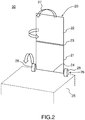
- the figure 2 schematically represents a deployable assembly 30 according to the invention.
- the deployable assembly 30 comprises a supporting structure 25, an assembly 20 of panels 21, 22 which can be deployed and orientated. In this example, only two panels 21 and 22 are shown. It is obvious that the assembly 20 can also include one or more other panels.
- the assembly 20 comprises an intermediate link defining an intermediate axis of rotation 23 of the panel 22 relative to the first panel 21.
- the assembly 20 comprises a main link defining a main axis of rotation 24 of the panel 21 relative to the supporting structure 25 shown in dotted lines in the figure.
- Each of the panels 21, 22 is connected to the adjacent panel by a hinge defining the intermediate axis of rotation 23.
- the assembly 20 is able to pass from a stored configuration in which the panels 21, 22 are folded over one another.
- the deployable assembly 30 comprises an articulation device 26 defining the main axis of rotation 24 of the assembly 20 of panels 21, 22 relative to the supporting structure 25.
- the main axis of rotation is on a first edge of a first 21 of the panels on one face of the supporting structure 25.
- the assembly 20 of panels 21, 22 is movable in rotation about the intermediate axes of rotation 23 and of the main axis of rotation 24 for change from the stored configuration to the deployed configuration and the assembly 20 of panels 21, 22 is only movable in rotation about the main axis of rotation 24 in the deployed configuration so as to orient the assembly 20 of panels 21, 22 by relative to the supporting structure 25. It is therefore in the deployed configuration, that is to say in the operational configuration, that the assembly 20 of panels 21, 22 can be oriented along the main axis of rotation 24.
- the assembly 20 of panels 21, 22 can be subjected to a first mode of bending, symbolized in this figure by the arrow 27, excited by the maneuver of the satellite but is, thanks to the invention, controlled by the articulation device 26 ensuring the orientation of the assembly 20 of panels 21, 22.
- the rotation of the assembly 20 of panels 21, 22 takes place around the one and only main axis of rotation 24.
- the deployment of the panels 21, 22 then, once deployed , the orientation of the assembly 20 of the panels 21, 22 are on a single axis, the main axis of rotation 24.
- This configuration is simple and allows to obtain a good rigidity of the assembly 20 on the supporting structure , even when the panels are deployed and the satellite changes attitude.
- the invention is not limited to a deployable assembly 30 comprising a set of panels 20 comprising two panels 21, 22.
- Each of the panels has ridges, and the main axis of rotation is on a first ridge of a first panel and the intermediate axes of rotation are advantageously on non-adjacent edges. This is particularly the case with rectangular panels, as shown in the figure 2 , but this is true for any polygonal shaped panel of degree greater than or equal to 4, that is to say with 4 or more edges.
- the main axis of rotation 24 and the intermediate axes of rotation 23 are parallel axes. This is true for rectangular panels, but the main axis of rotation 24 and the intermediate axes of rotation 23 can also be parallel for panels of pentagonal, hexagonal, octagonal, etc.
- the articulation device comprises two bearings 28, 29 on the first edge of the first panel 21 so as to make the assembly 20 of panels 21, 22 movable in rotation around the main axis of rotation 24.
- the figure 3 shows in more detail an example of an articulation device 26 of a set 20 of panels 21, 22 relative to the supporting structure 25.
- the articulation device 26 comprises the first bearing 28 on the first edge of the first panel 21.
- the articulation device 26 comprises a control device 31 comprising a geared motor 32 coupled to the first bearing 28 intended to orient the assembly 20 of panels 21, 22.
- the control device 31 comprises at least one damper 33 coupling the geared motor 32 and the first bearing 28.
- the purpose of the damper 33 is to 'introduce passive damping in the connection between the geared motor 32 and the first bearing 28.
- the damper 33 serves to limit or even eliminate the vibrations present at the level of the geared motor when the latter orients the assembly 30 of panels by through the first bearing 28.
- the damper 33 may for example be a part made of flexible material such as rubber or plastic to damp low-amplitude vibrations, a spring or preferably a viscoelastic insert.
- the articulation device 26 comprises prestressing means 34 associated with the second bearing 29 making it possible to avoid any play in the first and the second bearing 28, 29.
- the prestressing means 34 constitutes an anti-stress system. play by tensioning the articulation device 26 and the assembly 20 of panels 21, 22.
- the prestressing means can pre-stress the damper 33 and thus improves the control of the assembly 20 of panels 21, 22.
- the figure 4 schematically represents a control loop 40 of the geared motor 32 as a function of the position of the assembly 20 of panels 21, 22 around the main axis of rotation, according to the invention.
- the deployable assembly 30 includes a sensor 41, visible on the figure 3 , capable of determining the position of the assembly 20 of panels 21, 22.
- the deployable assembly 30 comprises a servo-control of the geared motor 32 as a function of the position of the assembly 20 of panels 21, 22.
- a setpoint 42 is transmitted to the gear motor 32 for orienting the assembly 20 of panels.
- the sensor 42 determines the position of the assembly 20 of panels.
- the information 43 of the position of the assembly 20 of panels is transmitted to a comparator 44 which compares the information 43 with the setpoint 42.
- the sensor 41 can be for example an optical sensor which determines the position of the assembly 20 of panels 21, 22.
- the sensor 41 can also be a force sensor which determines, from the perceived force, the position of the force. 'set 20 of panels 21, 22.
- This control loop can also advantageously receive a setpoint produced by the attitude control system of the satellite itself which includes other sensors. In other words, it is possible to envisage the servo loop 40 as being a sub-loop of the attitude and orbit control system of the satellite.
- the figure 5 represents different successive positions around the Earth of a satellite 50 according to the invention.
- the supporting structure is the satellite 50.
- the deployable structure comprises an assembly 20 of panels 51, 52, 53, 54, each of the panels being connected to the adjacent panel by a hinge defining an intermediate axis of rotation, and the assembly of panels is only movable in rotation about the main axis of rotation in the deployed configuration so as to orient the assembly of panels relative to the satellite 50.
- the assembly 20 of panels can comprise so-called main panels such as panels 51 and 52 and so-called secondary panels 53, 54, connected to one or more main panels by an intermediate link.
- other panels can just as easily be connected to the secondary panels, so as to form any possible configuration of the set of panels.
- the figure 5 represents a satellite 50 on an observation mission around the Earth having to both perform a pointing towards the ground to make one or more images of the Earth or download data to a station positioned on the ground and correctly orient the assembly 20 of panels towards the sun so as to charge the battery efficiently to operate the equipment on board the satellite 50.
- the set of panels is movable in rotation around the main axis of rotation in the deployed configuration.
- the assembly 20 of panels is orientable relative to the supporting structure and optimally oriented to capture the solar flux.
- the orientation of the set of solar panels is optimal, it is not necessary to provide too many.
- the satellite 50 can perform its observation mission without suffering a penalty of mass and bulk due to the solar panels.
- the satellite can always point towards the Earth and the assembly 20 of panels can be oriented towards the sun in order to ensure the need for energy and to operate the equipment on board the satellite.
- the invention therefore has the advantage of meeting both the constraints of pointing towards the ground for the observation mission and the efficient orientation of the set of panels towards the sun to charge the battery efficiently without a mass penalty. since it is then not necessary to provide too many solar panels.
- the attitude of the satellite is determined by one or more stellar trackers, better known under the Anglo-Saxon terminology “star tracker", optical device which measures the position of stars by photoelectric cells or cameras and which allows to deduce the attitude of the satellite.
- stellar trackers better known under the Anglo-Saxon terminology “star tracker”
- optical device which measures the position of stars by photoelectric cells or cameras and which allows to deduce the attitude of the satellite.
- These optical devices cannot look through the panels, which is problematic when the satellite is equipped with a large number of panel sets.
- the invention also makes it possible to solve this problem since it allows, as explained above, a saving of space due to a limited number of sets of panels.
- the control of the satellite is not penalized. Indeed, each additional link between the supporting structure and the panels represents an additional weak point in terms of vibration mode. In the presence of several connections, it is necessary then damping the modes of the set of panels with mechanical systems adding a mass constraint, an additional manufacturing cost and a complexity of use.
- the invention solves this problem by virtue of its device for articulation of all the panels.
- the first bending mode is controlled by the articulation device which allows the vibration to be controlled through the controller. If there is vibration in the panel assembly, the controller can send the command to the gear motor to dampen the vibrations.
- the spacing between the first and the second bearing along the first edge of the first panel increases the stiffness of the set of panels thanks to better rigidity and allows better frequency control.
Landscapes
- Engineering & Computer Science (AREA)
- Remote Sensing (AREA)
- Aviation & Aerospace Engineering (AREA)
- Life Sciences & Earth Sciences (AREA)
- Sustainable Development (AREA)
- Physics & Mathematics (AREA)
- Astronomy & Astrophysics (AREA)
- General Physics & Mathematics (AREA)
- Aerials With Secondary Devices (AREA)
- Details Of Aerials (AREA)
- Photovoltaic Devices (AREA)
Description
- La présente invention concerne un ensemble déployable comprenant une structure porteuse et un ensemble de panneaux, par exemple un satellite et un générateur solaire composé de plusieurs panneaux solaires. Elle s'applique notamment au domaine des équipements spatiaux qui doivent être déployés en orbite et plus particulièrement aux équipements spatiaux pour satellites, tels que des générateurs solaires. Néanmoins, l'ensemble déployable selon l'invention peut être appliqué à tout autre domaine où il est nécessaire d'articuler un ou plusieurs panneaux par rapport à un objet. Le panneau peut être rigide ou flexible.
- Un générateur solaire est constitué de panneaux solaires déployables et orientables. Un panneau solaire est un dispositif technologique énergétique constitué de capteurs solaires photovoltaïques destiné à convertir le rayonnement solaire en énergie électrique. Sur un satellite, le générateur solaire permet d'assurer l'apport d'énergie électrique et de faire fonctionner le matériel à son bord. Un générateur solaire peut être monté sur un satellite nécessitant un pointage précis, comme c'est le cas pour un satellite d'observation haute résolution. Les panneaux solaires peuvent présenter des modes de vibration basse fréquence non souhaités car perturbant le contrôle de la ligne de visée. Un satellite d'observation pointe souvent vers la Terre. Par contre, les panneaux solaires ne voient pas toujours le soleil, ce qui pose un problème d'apport d'énergie. Pour contrer ce problème, il est possible de monter davantage de panneaux solaires sur le satellite, mais cette solution présente l'inconvénient d'un surplus de masse et d'encombrement, surtout lors du lancement du satellite qui est contenu sous la coiffe de la fusée.
- Il existe des satellites pouvant s'orienter selon leur phase d'activité. En phase d'observation, le satellite est complètement orienté vers le sol terrestre, un flux solaire réduit parvient sur le générateur solaire. En phase de stockage d'énergie, le satellite s'oriente de façon à ce que ses panneaux solaires soient orientés de manière optimale vers le soleil, c'est-à-dire avec la surface normale aux rayons. Néanmoins, lorsque le satellite passe au-dessus de sa station au sol, il se réoriente vers celle-ci afin de lui transférer les informations de sa mission. Il est donc difficile de concilier la mission d'observation avec la recharge énergétique.
- De plus, le satellite tourne le dos au soleil et le télescope regarde l'espace froid à une température d'environ 3 Kelvin, au lieu de regarder vers la Terre en étant dans un environnement à une température d'environ 10 à 30 °C. Ces situations compliquent la régulation et le design thermique du télescope.
- Par ailleurs, lorsque le satellite est dos au soleil, la cavité du télescope est parfois face au 'vent relatif' lié à la vitesse orbitale. Des particules de cet environnement peuvent éroder ou déformer les composants internes de la cavité. Sur la durée de vie requise du télescope, il est possible de rendre le télescope robuste face à de telles contraintes environnementales, mais cela signifie une plus haute exigence de la qualité du télescope, impliquant par là-même des coûts supplémentaires.
- Certains satellites disposent de deux bras d'articulation. L'un des bras se situe dans le plan des panneaux solaires et permet le déploiement des panneaux solaires de la configuration stockée sur le satellite à la configuration déployée. Le deuxième bras est motorisé et permet d'orienter le générateur vers le soleil, le deuxième bras se terminant par exemple par deux branches, le bras est relié au satellite, les deux branches sont reliées au générateur solaire. Le bras permet une rotation de 360° du générateur solaire. Une telle configuration est décrite par exemple dans les documents
JP2008/221876 US 5697582 etEP 0716365 . Ainsi, il est possible pour le satellite de s'orienter de manière à pointer complètement vers le sol et d'orienter son générateur solaire vers le soleil pour assurer l'apport d'énergie. Mais cette solution impose la présence de deux articulations entre le satellite et le générateur solaire : l'articulation dédiée au déploiement des panneaux solaires et l'articulation dédiée à l'orientation du générateur solaire. Cette configuration n'est pas optimale pour la raideur du générateur solaire. La prise d'images doit être effectuée de manière très précise. Le satellite doit pouvoir changer d'attitude, parfois rapidement, avec une bonne stabilité et avoir une haute précision de pointage. La présence de deux articulations entre le satellite et le générateur solaire génère un problème d'amortissement. En effet, pendant le changement d'attitude du satellite, le générateur solaire peut alors être soumis à un premier mode de flexion excité par la manœuvre du satellite mais non contrôlé par le bras motorisé assurant l'orientation du générateur solaire. Les vibrations rendent alors la stabilisation du pointage difficile. - Le document
EP 2468630 divulgue une structure déployable, constituée de panneaux formant une antenne équipée d'un générateur solaire, correspondant au préambule de la revendication 1. - L'invention vise à pallier tout ou partie des problèmes cités plus haut en proposant un ensemble déployable avec une seule articulation, c'est-à-dire sans un deuxième bras d'orientation, permettant de gagner en rigidité et de contrôler au mieux les vibrations.
- A cet effet, l'invention a pour objet un ensemble déployable selon la revendication 1.
- Selon un mode de réalisation, chacun des panneaux ayant des arêtes, l'axe principal de rotation est sur une première arête d'un premier des panneaux et les axes de rotation intermédiaires sont sur des arêtes non adjacentes.
- Selon un autre mode de réalisation, l'axe principal de rotation et les axes de rotation intermédiaires sont des axes parallèles.
- Selon un autre mode de réalisation, l'ensemble déployable comprend un capteur apte à déterminer la position de l'ensemble de panneaux, et il comprend un asservissement du motoréducteur en fonction de la position de l'ensemble de panneaux autour de l'axe principal de rotation.
- Selon un autre mode de réalisation, le dispositif d'articulation comprend un moyen de précontrainte associé au second palier permettant d'éviter tout jeu dans le premier et le second palier.
- Selon un mode particulier de réalisation, les panneaux de l'ensemble déployable sont des panneaux solaires et la structure porteuse est un satellite.
- L'invention sera mieux comprise et d'autres avantages apparaîtront à la lecture de la description détaillée d'un mode de réalisation donné à titre d'exemple, description illustrée par le dessin joint dans lequel :
- la
figure 1 représente schématiquement un ensemble de panneaux déployable et orientable selon l'art antérieur, - la
figure 2 représente schématiquement un ensemble de panneaux déployable et orientable selon l'invention, - la
figure 3 représente un dispositif d'articulation d'un ensemble de panneaux par rapport à une structure porteuse, - la
figure 4 représente schématiquement une boucle d'asservissement d'un motoréducteur en fonction de la position de l'ensemble de panneaux, selon l'invention, - la
figure 5 représente différentes positions successives autour de la Terre d'un satellite d'observation selon l'invention. - Par souci de clarté, les mêmes éléments porteront les mêmes repères dans les différentes figures.
- L'invention est décrite dans le domaine des équipements spatiaux, dans le cas où les panneaux sont des panneaux solaires formant un générateur solaire et la structure porteuse est un satellite. Il est bien évident que l'invention peut s'appliquer à tout autre domaine dans lequel un ensemble de panneaux est relié à une structure porteuse pour former un ensemble déployable, par exemple un ensemble de panneaux d'antenne de télécommunication.
- Dans cette demande, il est question d'un ensemble de panneaux, chacun des panneaux étant relié au panneau adjacent par une charnière définissant un axe de rotation intermédiaire, apte à passer d'une configuration stockée dans laquelle les panneaux sont repliés les uns sur les autres à une configuration déployée, par rotation des panneaux autour des axes de rotation intermédiaires respectifs, dans laquelle les panneaux sont disposés sensiblement dans un même plan. L'ensemble de panneaux est relié à une structure porteuse le long d'une arête d'un des panneaux, appelé premier panneau, par une liaison principale définissant un axe de rotation principal. Et chaque panneau est relié le long d'une de ses arêtes à son panneau voisin par une liaison intermédiaire définissant un axe de rotation intermédiaire. Chaque panneau est donc mobile en rotation autour de sa liaison intermédiaire et l'ensemble de panneaux est mobile en rotation autour de sa liaison principale. En configuration stockée, les panneaux sont repliés les uns sur les autres et sont empilés au niveau d'une face de la structure porteuse. La configuration stockée permet le stockage de l'ensemble des panneaux, notamment pendant la mise en orbite du satellite lorsque celui-ci est stocké sous la coiffe de la fusée, dans un espace restreint. En configuration déployée, les panneaux sont disposés sensiblement dans un même plan. Pour passer de la configuration stockée à la configuration déployée, le premier panneau a effectué un mouvement de rotation autour de la liaison principale et chacun des panneaux a effectué un mouvement de rotation autour de sa liaison intermédiaire. La configuration déployée correspond à la configuration opérationnelle de l'ensemble de panneaux. Autrement dit, c'est en configuration déployée que l'ensemble de panneaux est orienté en fonction des besoins du satellite. L'ensemble de panneaux en configuration déployée est orienté vers le soleil lorsqu'il y a besoin de convertir le rayonnement solaire en énergie électrique. Tout en restant en configuration déployée, cette orientation est amenée à être modifiée pour conserver une orientation optimale des panneaux solaires par rapport au soleil notamment lorsque le satellite se déplace sur son orbite. La configuration déployée peut également être appelée configuration opérationnelle. Autrement dit, dans la configuration déployée les panneaux remplissent la fonction pour laquelle ils sont destinés : les capteurs solaires fournissent une énergie électrique, les panneaux d'antenne reçoivent ou émettent un rayonnement électromagnétique... Dans la configuration stockée, les panneaux sont rangés les uns contre les autres, par exemple en phase de lancement du satellite pour leur permettre de prendre place dans la coiffe d'un lanceur.
- Par ailleurs, dans le cadre d'une application dans le domaine des équipements spatiaux, les panneaux peuvent être rigides ou flexibles. Dans le cas d'un panneau flexible, il est possible d'avoir un ensemble de panneaux comprenant par exemple au moins un mètre-ruban supportant une membrane souple. La membrane souple correspond à un panneau. Dans cet exemple, l'invention est à comprendre de manière analogue. La configuration stockée dans laquelle les panneaux sont repliés les uns sur les autres et empilés au niveau d'une face de la structure porteuse est à comprendre comme une configuration dans laquelle le mètre-ruban et le panneau, c'est-à-dire la membrane souple, sont enroulés autour d'un mandrin et stockés au niveau d'une face de la structure porteuse. Et de manière similaire, pour passer de la configuration stockée à la configuration déployée, le premier panneau effectue un mouvement de rotation autour de la liaison principale. Autrement dit, la membrane souple passe en configuration déployée par déploiement du mètre-ruban en effectuant un mouvement de rotation autour du mandrin.
- La
figure 1 représente schématiquement un ensemble 10 de panneaux 11, 12 déployable et orientable selon l'art antérieur. Dans cet exemple, seuls deux panneaux 11 et 12 sont représentés. Il est bien évident que l'ensemble 10 peut aussi comprendre un ou plusieurs autres panneaux. L'ensemble 10 comprend une liaison intermédiaire définissant un axe intermédiaire de rotation 13 du panneau 12 par rapport au premier panneau 11. L'ensemble 10 de panneaux est relié à une structure porteuse 9, représentée schématiquement en pointillés sur la figure, par un bras 14 s'étendant vers l'ensemble 10 de panneaux par deux bras 15, 16. Les bras 15, 16 sont reliés à la première arête 17 du premier panneau 11. Le bras 14 est relié à un dispositif de commande 18 qui permet d'orienter l'ensemble 10 de panneaux vers le soleil. Le bras 14 associé au dispositif de commande 18 permet une rotation de 360° de l'ensemble 10 de panneaux. Ainsi, il est possible pour le satellite de s'orienter de manière à pointer complètement vers le sol et d'orienter l'ensemble 10 de panneaux 11, 12 vers le soleil pour assurer l'apport d'énergie. Selon l'art antérieur, il y a donc une articulation dédiée au déploiement des panneaux et une articulation dédiée à l'orientation de l'ensemble 10 de panneaux 11, 12. Cette configuration n'est pas optimale pour la raideur de l'ensemble 10 de panneaux. En effet, quand le satellite change d'attitude, il faut avoir une haute précision de pointage au niveau du télescope embarqué. La présence de deux articulations entre le satellite et l'ensemble 10 de panneaux génère un problème d'amortissement. En effet, pendant le changement d'attitude du satellite, l'ensemble de panneaux peut alors être soumis à un premier mode de flexion, symbolisé par la flèche 19, excité par la manœuvre du satellite mais non contrôlé par le bras 14 motorisé assurant l'orientation de l'ensemble 10 de panneaux. - La
figure 2 représente schématiquement un ensemble déployable 30 selon l'invention. L'ensemble déployable 30 comprend une structure porteuse 25, un ensemble 20 de panneaux 21, 22 déployable et orientable. Dans cet exemple, seuls deux panneaux 21 et 22 sont représentés. Il est bien évident que l'ensemble 20 peut aussi comprendre un ou plusieurs autres panneaux. L'ensemble 20 comprend une liaison intermédiaire définissant un axe intermédiaire de rotation 23 du panneau 22 par rapport au premier panneau 21. L'ensemble 20 comprend une liaison principale définissant un axe principal de rotation 24 du panneau 21 par rapport à la structure porteuse 25 représentée en pointillés sur la figure. Chacun des panneaux 21, 22 est relié au panneau adjacent par une charnière définissant l'axe de rotation intermédiaire 23. L'ensemble 20 est apte à passer d'une configuration stockée dans laquelle les panneaux 21, 22 sont repliés les uns sur les autres à une configuration déployée, par rotation des panneaux 21, 22 autour des axes de rotation intermédiaires respectifs, dans laquelle les panneaux 21, 22 sont disposés sensiblement dans un même plan. L'ensemble déployable 30 comprend un dispositif d'articulation 26 définissant l'axe principal de rotation 24 de l'ensemble 20 de panneaux 21, 22 par rapport à la structure porteuse 25. Selon l'invention, l'axe principal de rotation est sur une première arête d'un premier 21 des panneaux sur une face de la structure porteuse 25. L'ensemble 20 de panneaux 21, 22 est mobile en rotation autour des axes de rotation intermédiaires 23 et de l'axe principal de rotation 24 pour passer de la configuration stockée à la configuration déployée et l'ensemble 20 de panneaux 21, 22 est seulement mobile en rotation autour de l'axe principal de rotation 24 en configuration déployée de façon à orienter l'ensemble 20 de panneaux 21, 22 par rapport à la structure porteuse 25. C'est donc en configuration déployée, c'est-à-dire en configuration opérationnelle, que l'ensemble 20 de panneaux 21, 22 est orientable selon l'axe principal de rotation 24. Comme expliqué précédemment, pendant le changement d'attitude du satellite, l'ensemble 20 de panneaux 21, 22 peut être soumis à un premier mode de flexion, symbolisé sur cette figure par la flèche 27, excité par la manœuvre du satellite mais est, grâce à l'invention, contrôlé par le dispositif d'articulation 26 assurant l'orientation de l'ensemble 20 de panneaux 21, 22. En position déployée, la rotation de l'ensemble 20 de panneaux 21, 22 se fait autour du seul et unique axe principal de rotation 24. Il n'y a pas d'autre articulation qui intervient dans la rotation de l'ensemble 20 de panneaux 21, 22. Autrement dit, le déploiement des panneaux 21, 22 puis, une fois déployés, l'orientation de l'ensemble 20 des panneaux 21, 22 se font sur un seul axe, l'axe principal de rotation 24. Cette configuration est simple et permet d'obtenir une bonne rigidité de l'ensemble 20 sur la structure porteuse, même lorsque les panneaux sont déployés et que le satellite change d'attittude. - Comme déjà mentionné, l'invention ne se limite pas à un ensemble déployable 30 comprenant un ensemble de panneaux 20 comprenant deux panneaux 21, 22. Chacun des panneaux a des arêtes, et l'axe principal de rotation est sur une première arête d'un premier panneau et les axes de rotation intermédiaires sont avantageusement sur des arêtes non adjacentes. C'est notamment le cas avec des panneaux rectangulaires, comme représenté sur la
figure 2 , mais cela est vrai pour tout panneau de forme polygonale de degré supérieur ou égal à 4, c'est-à-dire à 4 arêtes ou plus. - Avantageusement, et comme représenté sur la
figure 2 , l'axe principal de rotation 24 et les axes de rotation intermédiaires 23 sont des axes parallèles. Cela est vrai pour des panneaux rectangulaires, mais l'axe principal de rotation 24 et les axes de rotation intermédiaires 23 peuvent aussi être parallèles pour des panneaux de forme pentagonale, hexagonale, octogonale, etc. - Comme représenté sur la
figure 2 , le dispositif d'articulation comprend deux paliers 28, 29 sur la première arête du premier panneau 21 de façon à rendre l'ensemble 20 de panneaux 21, 22 mobile en rotation autour de l'axe principal de rotation 24. - La
figure 3 représente plus en détail un exemple de dispositif d'articulation 26 d'un ensemble 20 de panneaux 21, 22 par rapport à la structure porteuse 25. Le dispositif d'articulation 26 comprend le premier palier 28 sur la première arête du premier panneau 21. Le dispositif d'articulation 26 comprend un dispositif de commande 31 comprenant un motoréducteur 32 accouplé au premier palier 28 destiné à orienter l'ensemble 20 de panneaux 21, 22. Le dispositif de commande 31 comprend au moins un amortisseur 33 accouplant le motoréducteur 32 et le premier palier 28. L'amortisseur 33 a pour but d'introduire un amortissement passif dans la liaison entre le motoréducteur 32 et le premier palier 28. Autrement dit, l'amortisseur 33 sert à limiter, voire supprimer les vibrations présentes au niveau du motoréducteur quand celui-ci oriente l'ensemble 30 de panneaux par l'intermédiaire du premier palier 28. L'amortisseur 33 peut être par exemple une pièce en matériau souple tel que le caoutchouc ou le plastique pour amortir les vibrations de faibles amplitudes, un ressort ou préférentiellement un insert viscoélastique. - Selon un mode de réalisation préférentiel, le dispositif d'articulation 26 comprend moyen de précontrainte 34 associé au second palier 29 permettant d'éviter tout jeu dans le premier et le second palier 28, 29. Le moyen de précontrainte 34 constitue un système anti-jeu par mise en tension du dispositif d'articulation 26 et de l'ensemble 20 de panneaux 21, 22. Le moyen de précontrainte peut précontraindre l'amortisseur 33 et améliore ainsi le contrôle de l'ensemble 20 de panneaux 21, 22.
- La
figure 4 représente schématiquement une boucle d'asservissement 40 du motoréducteur 32 en fonction de la position de l'ensemble 20 de panneaux 21, 22 autour de l'axe principal de rotation, selon l'invention. L'ensemble déployable 30 comprend un capteur 41, visible sur lafigure 3 , apte à déterminer la position de l'ensemble 20 de panneaux 21, 22. L'ensemble déployable 30 comprend un asservissement du motoréducteur 32 en fonction de la position de l'ensemble 20 de panneaux 21, 22. Une consigne 42 est transmise au motoréducteur 32 pour orienter l'ensemble 20 de panneaux. Le capteur 42 détermine la position de l'ensemble 20 de panneaux. L'information 43 de la position de l'ensemble 20 de panneaux est transmise à un comparateur 44 qui compare l'information 43 à la consigne 42. Si l'information 43 est différente de la consigne 42, le comparateur 44 transmet une correction 45 au motoréducteur de façon à corriger l'orientation de l'ensemble 20 de panneaux. Ainsi, grâce à la boucle d'asservissement, une orientation précise de l'ensemble 20 de panneaux est assurée. Le capteur 41 peut être par exemple un capteur optique qui détermine la position de l'ensemble 20 de panneaux 21, 22. Le capteur 41 peut aussi être un capteur d'effort qui détermine, à partir de la force perçue, la position de l'ensemble 20 de panneaux 21, 22. Cette boucle de contrôle pourra aussi avantageusement recevoir une consigne élaborée par le système de contrôle d'attitude du satellite lui-même qui comprend d'autres capteurs. Autrement dit, il est possible d'envisager la boucle d'asservissement 40 comme étant une sous-boucle du système de contrôle d'attitude et d'orbite du satellite. - La
figure 5 représente différentes positions successives autour de la Terre d'un satellite 50 selon l'invention. Autrement dit, la structure porteuse est le satellite 50. La structure déployable comprend un ensemble 20 de panneaux 51, 52, 53, 54, chacun des panneaux étant relié au panneau adjacent par une charnière définissant un axe de rotation intermédiaire, et l'ensemble de panneaux est seulement mobile en rotation autour de l'axe principal de rotation en configuration déployée de façon à orienter l'ensemble de panneaux par rapport au satellite 50. On peut noter au passage que l'invention s'applique à un ensemble de panneaux comprenant plus que deux panneaux comme représenté sur lafigure 5 . L'ensemble 20 de panneaux peut comprendre des panneaux dits principaux tels que les panneaux 51 et 52 et des panneaux dits secondaires 53, 54, reliés à un ou plusieurs panneaux principaux par une liaison intermédiaire. Sur le même principe, d'autres panneaux peuvent tout aussi bien être reliés aux panneaux secondaires, de façon à former toute configuration possible de l'ensemble de panneaux. - La
figure 5 représente un satellite 50 en mission d'observation autour de la Terre devant à la fois effectuer un pointage vers le sol pour faire une ou plusieurs images de la Terre ou télécharger des données vers une station positionnée au sol et orienter correctement l'ensemble 20 de panneaux vers le soleil de façon à charger la batterie avec efficacité pour faire fonctionner le matériel à bord du satellite 50. Grâce à l'invention, dans une trajectoire allant du pôle Sud au pôle Nord, on voit que le satellite 50 pointe toujours vers la Terre, ce qui permet de réaliser la mission d'observation comme souhaité. Et selon la position du satellite 50 autour de la Terre et donc selon son orientation par rapport au soleil, l'ensemble de panneaux est mobile en rotation autour de l'axe principal de rotation en configuration déployée. Ainsi, l'ensemble 20 de panneaux est orientable par rapport à la structure porteuse et orienté de manière optimale pour capter le flux solaire. Comme l'orientation de l'ensemble de panneaux solaires est optimale, il n'est pas nécessaire d'en prévoir un trop grand nombre. Ainsi, le satellite 50 peut effectuer sa mission d'observation sans subir une pénalité de masse et d'encombrement due aux panneaux solaires. - Ainsi, le satellite peut toujours pointer vers la Terre et l'ensemble 20 de panneaux peut être orienté vers le soleil afin d'assurer le besoin d'énergie et faire fonctionner le matériel embarqué à bord du satellite. L'invention présente donc l'avantage de répondre à la fois aux contraintes de pointage vers le sol pour la mission d'observation et l'orientation efficace de l'ensemble de panneaux vers le soleil pour charger la batterie avec efficacité sans pénalité de masse puisqu'il n'est alors pas nécessaire de prévoir un trop grand nombre de panneaux solaires.
- De manière générale, l'attitude du satellite est déterminée par un ou plusieurs suiveurs stellaires, plus connu sous la terminologie anglo-saxonne « star tracker », dispositif optique qui mesure la position des étoiles par des cellules photoélectriques ou caméras et qui permet d'en déduire l'attitude du satellite. Ces dispositifs optiques ne peuvent pas regarder à travers les panneaux, ce qui est problématique quand le satellite est équipé d'un grand nombre d'ensembles de panneaux. L'invention permet également de résoudre ce problème puisqu'elle permet, comme expliqué ci-dessus, un gain de place du fait d'un nombre d'ensembles de panneaux limité.
- De plus, comme le satellite ne présente qu'une seule liaison principale pour l'orientation de l'ensemble de panneaux, le contrôle du satellite n'est pas pénalisé. En effet, chaque liaison additionnelle entre la structure porteuse et les panneaux représente un point faible supplémentaire en termes de mode de vibration. En présence de plusieurs liaisons, il faut alors amortir les modes de l'ensemble de panneaux avec des systèmes mécaniques ajoutant une contrainte de masse, un surcoût de fabrication et une complexité d'utilisation. L'invention résout ce problème grâce à son dispositif d'articulation de l'ensemble des panneaux. Le premier mode de flexion est contrôlé par le dispositif d'articulation qui permet de contrôler les vibrations par le biais du dispositif de commande. S'il y a des vibrations dans l'ensemble de panneaux, le dispositif de commande peut envoyer l'ordre au motoréducteur pour amortir les vibrations.
- Par ailleurs, l'écartement entre le premier et le second palier le long de la première arête du premier panneau augmente la raideur de l'ensemble de panneaux grâce à une meilleure rigidité et permet un meilleur contrôle en fréquence.
Claims (6)
- Ensemble déployable (30) comprenant :• une structure porteuse (25, 50),• un ensemble (20) de panneaux (21, 22 ; 51, 52, 53, 54), chacun des panneaux (21, 22 ; 51, 52, 53, 54) étant relié au panneau adjacent par une charnière définissant un axe de rotation intermédiaire, apte à passer d'une configuration stockée dans laquelle les panneaux (21, 22; 51, 52, 53, 54) sont repliés les uns sur les autres à une configuration déployée, par rotation des panneaux (21, 22 ; 51, 52, 53, 54) autour des axes de rotation intermédiaires respectifs, dans laquelle les panneaux sont disposés sensiblement dans un même plan,• un dispositif d'articulation (26) définissant un unique axe principal de rotation de l'ensemble (20) de panneaux (21, 22 ; 51, 52, 53, 54) par rapport à la structure porteuse (25, 50),l'axe principal de rotation étant sur une première arête d'un premier (21, 51) des panneaux sur une face de la structure porteuse (25, 50), l'ensemble (20) de panneaux (21, 22 ; 51, 52, 53, 54) étant mobile en rotation autour des axes de rotation intermédiaires et de l'axe principal de rotation pour passer de la configuration stockée à la configuration déployée et l'ensemble (20) de panneaux (21, 22 ; 51, 52, 53, 54) étant seulement mobile en rotation autour de l'axe principal de rotation en configuration déployée de façon à orienter l'ensemble (20) de panneaux (21, 22 ; 51, 52, 53, 54) par rapport à la structure porteuse (25, 50),
caractérisé en ce que le dispositif d'articulation (26) comprend un premier palier (28) et un deuxième palier (29) sur la première arête du premier panneau (21, 51) de façon à rendre l'ensemble (20) de panneaux mobile en rotation autour de l'axe principal de rotation, l'axe principal de rotation étant sur une première arête d'un premier (21, 51) des panneaux, en ce que le dispositif d'articulation (26) comprend un dispositif de commande (31) comprenant un motoréducteur (32) accouplé au premier palier (28) destiné à orienter l'ensemble (20, 50) de panneaux, et en ce que le dispositif de commande (31) comprend au moins un amortisseur (33) accouplant le motoréducteur (32) et le premier palier (28). - Ensemble déployable (30) selon la revendication 1, chacun des panneaux (21, 22 ; 51, 52, 53, 54) ayant des arêtes, caractérisé en ce que les axes de rotation intermédiaires sont sur des arêtes non adjacentes.
- Ensemble déployable (30) selon l'une quelconque des revendications précédentes, caractérisé en ce que l'axe principal de rotation et les axes de rotation intermédiaires sont des axes parallèles.
- Ensemble déployable (30) selon l'une quelconque des revendications 1 à 3, caractérisé en ce qu'il comprend un capteur (41) apte à déterminer la position de l'ensemble (20) de panneaux, et en ce qu'il comprend un asservissement du motoréducteur (32) en fonction de la position de l'ensemble (20) de panneaux autour de l'axe principal de rotation.
- Ensemble déployable (30) selon l'une quelconque des revendications 1 à 4, caractérisé en ce que le dispositif de commande (31) comprend un moyen de précontrainte (34) associé au second palier (29) permettant d'éviter tout jeu dans le premier et le second palier (28, 29).
- Ensemble déployable (30) selon l'une quelconque des revendications précédentes, caractérisé en ce que les panneaux (21, 22 ; 51, 52, 53, 54) sont des panneaux solaires et en ce que la structure porteuse (25, 50) est un satellite.
Applications Claiming Priority (1)
| Application Number | Priority Date | Filing Date | Title |
|---|---|---|---|
| FR1501981A FR3041608B1 (fr) | 2015-09-25 | 2015-09-25 | Ensemble deployable |
Publications (2)
| Publication Number | Publication Date |
|---|---|
| EP3147223A1 EP3147223A1 (fr) | 2017-03-29 |
| EP3147223B1 true EP3147223B1 (fr) | 2020-10-21 |
Family
ID=55129924
Family Applications (1)
| Application Number | Title | Priority Date | Filing Date |
|---|---|---|---|
| EP16188438.2A Active EP3147223B1 (fr) | 2015-09-25 | 2016-09-13 | Ensemble deployable |
Country Status (4)
| Country | Link |
|---|---|
| US (1) | US10207823B2 (fr) |
| EP (1) | EP3147223B1 (fr) |
| KR (1) | KR20170037551A (fr) |
| FR (1) | FR3041608B1 (fr) |
Families Citing this family (5)
| Publication number | Priority date | Publication date | Assignee | Title |
|---|---|---|---|---|
| CN109941462B (zh) * | 2017-12-20 | 2022-08-12 | 中国电子科技集团公司第四十八研究所 | 适用于临近空间浮空器柔性光伏组件的安装结构及安装方法 |
| CN112298610B (zh) * | 2020-09-30 | 2022-07-12 | 北京空间飞行器总体设计部 | 一种太阳翼及其分段式二次展开铰链 |
| CN112623280A (zh) * | 2021-01-04 | 2021-04-09 | 上海宇航系统工程研究所 | 一种两自由度太阳电池阵展开装置 |
| CN114275195B (zh) * | 2021-11-23 | 2023-08-29 | 上海宇航系统工程研究所 | 一种适用于空间环境的小型化可重复展收机构 |
| CN116639266B (zh) * | 2023-07-27 | 2023-10-13 | 航天恒星科技有限公司 | 一种多功能式卫星构型 |
Family Cites Families (28)
| Publication number | Priority date | Publication date | Assignee | Title |
|---|---|---|---|---|
| DE3376549D1 (en) * | 1983-09-03 | 1988-06-16 | Erno Raumfahrttechnik Gmbh | Satellite system with variable configuration |
| DE4114804A1 (de) * | 1991-05-07 | 1992-11-12 | Messerschmitt Boelkow Blohm | Vorrichtung zur lageregelung von satelliten mit solardruckmomenten |
| US5314146A (en) * | 1992-03-13 | 1994-05-24 | Spectrum Astro, Inc. | Multi-mission spacecraft bus having space frame structural design |
| US5344104A (en) * | 1992-09-21 | 1994-09-06 | General Electric Co. | Low cost, selectable configuration spacecraft |
| US5520747A (en) * | 1994-05-02 | 1996-05-28 | Astro Aerospace Corporation | Foldable low concentration solar array |
| US5669586A (en) * | 1994-12-06 | 1997-09-23 | Space Systems/Loral, Inc. | Satellite gravity gradient compensation using on-orbit solar array reorientation |
| US5833175A (en) * | 1995-12-22 | 1998-11-10 | Hughes Electronics Corporation | Spacecraft with large east-west dimensions |
| US5927654A (en) * | 1997-05-16 | 1999-07-27 | Lockheed Martin Corp. | Spacecraft with active antenna array protected against temperature extremes |
| US6102339A (en) * | 1998-04-17 | 2000-08-15 | Turbosat Technology, Inc. | Sun-synchronous sun ray blocking device for use in a spacecraft having a directionally controlled main body |
| US6038736A (en) * | 1998-06-29 | 2000-03-21 | Lockheed Martin Corporation | Hinge for deployable truss |
| US20030057328A1 (en) * | 2001-09-24 | 2003-03-27 | Arthur Maruno | Spacecraft having a nonuniform body shape |
| JP4013543B2 (ja) * | 2001-12-28 | 2007-11-28 | 三菱電機株式会社 | 放熱装置 |
| JP4094930B2 (ja) * | 2002-10-24 | 2008-06-04 | 真一 中須賀 | 人工衛星 |
| FR2846298A1 (fr) * | 2002-10-29 | 2004-04-30 | Cit Alcatel | Ensemble articule de panneaux de generateur solaire et vehicule spatial |
| US8146867B2 (en) * | 2004-06-14 | 2012-04-03 | Aeroastro, Inc. | Modular spacecraft design architecture |
| US7478782B2 (en) * | 2004-11-16 | 2009-01-20 | The Boeing Company | System and method incorporating adaptive and reconfigurable cells |
| US20070029446A1 (en) * | 2005-05-02 | 2007-02-08 | Mosher Todd J | Modular platform architecture for satellites |
| JP2008221876A (ja) * | 2007-03-08 | 2008-09-25 | Mitsubishi Electric Corp | 人工衛星搭載用太陽電池パネル、及び人工衛星 |
| US8757554B1 (en) * | 2009-09-09 | 2014-06-24 | MMA Design, LLC | Deployable and tracked solar array mechanism for nano-satellites |
| FR2969580B1 (fr) * | 2010-12-23 | 2013-08-16 | Thales Sa | Structure deployable formant une antenne equipee d'un generateur solaire pour un satellite |
| US8960608B2 (en) * | 2012-02-07 | 2015-02-24 | Lockheed Martin Corporation | Deployable radiator having an increased view factor |
| WO2014024199A1 (fr) * | 2012-08-08 | 2014-02-13 | Halsband Arie | Micro-satellite de faible volume comprenant panneaux enroulés souples extensibles après lancement |
| US9296493B2 (en) * | 2013-02-28 | 2016-03-29 | The Boeing Company | Spacecraft with open sides |
| US9352855B2 (en) * | 2013-04-09 | 2016-05-31 | Lockheed Martin Corporation | Heat generating transfer orbit shield |
| FR3014849B1 (fr) * | 2013-12-13 | 2018-06-15 | Astrium Sas | Radiateur deployable pour satellite stabilise trois axes |
| US9573702B1 (en) * | 2014-03-27 | 2017-02-21 | Lockheed Martin Corporation | Deployed radar panel for space situational awareness |
| US10144533B2 (en) * | 2014-05-14 | 2018-12-04 | California Institute Of Technology | Large-scale space-based solar power station: multi-scale modular space power |
| FR3023264B1 (fr) * | 2014-07-04 | 2017-11-24 | Thales Sa | Satellite a maitre couple variable |
-
2015
- 2015-09-25 FR FR1501981A patent/FR3041608B1/fr active Active
-
2016
- 2016-09-12 US US15/263,068 patent/US10207823B2/en active Active
- 2016-09-13 EP EP16188438.2A patent/EP3147223B1/fr active Active
- 2016-09-23 KR KR1020160122294A patent/KR20170037551A/ko not_active Withdrawn
Non-Patent Citations (1)
| Title |
|---|
| None * |
Also Published As
| Publication number | Publication date |
|---|---|
| US10207823B2 (en) | 2019-02-19 |
| US20170088292A1 (en) | 2017-03-30 |
| KR20170037551A (ko) | 2017-04-04 |
| FR3041608B1 (fr) | 2018-04-13 |
| EP3147223A1 (fr) | 2017-03-29 |
| FR3041608A1 (fr) | 2017-03-31 |
Similar Documents
| Publication | Publication Date | Title |
|---|---|---|
| EP3390230B1 (fr) | Procédé de commande de guidage d'attitude d'un satellite, satellite, pluralités de satellites et programme d'ordinateur associé | |
| EP3147223A1 (fr) | Ensemble deployable | |
| EP3157815B1 (fr) | Procédé de contrôle d'orbite d'un satellite en orbite terrestre, satellite et système de contrôle d'orbite d'un tel satellite | |
| EP2758311B1 (fr) | Procede de controle d'attitude d'un satellite et satellite commande en attitude | |
| EP2181923B1 (fr) | Procédé et système de désaturation des roues d'inertie d'un engin spatial | |
| EP3074309B1 (fr) | Procédé et dispositif de commande d'une phase d'acquisition du soleil par un engin spatial | |
| FR2932163A1 (fr) | Procede de commande d'attitude de satellite et satellite commande en attitude | |
| EP3921235B1 (fr) | Procédé de contrôle d'attitude d'un satellite en mode survie sans connaissance a priori de l'heure locale de l'orbite du satellite | |
| EP0435708A2 (fr) | Procédé de contrôle d'attitude en roulis et en lacet d'un satellite | |
| EP3201091B1 (fr) | Procédé de contrôle d'attitude d'un satellite en mode survie, satellite adapté et procédé de commande à distance d'un tel satellite | |
| JPH02262500A (ja) | 衛星制御システム | |
| EP2878539B1 (fr) | Système de tuyères et procédé pour le contrôle d'orbite et d'attitude pour satellite géostationnaire | |
| FR2789653A1 (fr) | Satellite a generateur solaire sur bras depliable et procede de mise a poste d'un tel satellite | |
| EP2468630A2 (fr) | Structure deployable formant une antenne equipee d'un generateur solaire pour un satellite | |
| FR2945515A1 (fr) | Systeme comportant une sonde spatiale mere formant vehicule spatial porteur et une pluralite de sondes spatiales filles | |
| EP0064917B1 (fr) | Procédé de mise sur orbite d'un satellite artificiel | |
| FR2601159A1 (fr) | Procedure de repointage rapide des satellites a pointage terrestre, et notamment des satellites geostationnaires de telecommunication a stabilisation par volant d'inertie | |
| FR2974787A1 (fr) | Dispositif de protection d'un instrument optique multifaisceaux | |
| EP1740457B1 (fr) | Satellite, procede et flotte de satellites d'observation d'un corps celeste | |
| FR2804765A1 (fr) | Systeme de moment a commande de lacet | |
| EP1635485B1 (fr) | Procédé de transmission optique entre un terminal embarqué sur un engin spatial et un terminal distant, et engin spatial adapté pour un tel procédé | |
| EP1676777A1 (fr) | Satellite pourvu de moyens pour contrer la pression solaire | |
| WO2025201831A1 (fr) | Procédé de contrôle d'attitude en mode survie d'un satellite embarquant un instrument sensible au rayonnement solaire |
Legal Events
| Date | Code | Title | Description |
|---|---|---|---|
| PUAI | Public reference made under article 153(3) epc to a published international application that has entered the european phase |
Free format text: ORIGINAL CODE: 0009012 |
|
| STAA | Information on the status of an ep patent application or granted ep patent |
Free format text: STATUS: THE APPLICATION HAS BEEN PUBLISHED |
|
| AK | Designated contracting states |
Kind code of ref document: A1 Designated state(s): AL AT BE BG CH CY CZ DE DK EE ES FI FR GB GR HR HU IE IS IT LI LT LU LV MC MK MT NL NO PL PT RO RS SE SI SK SM TR |
|
| AX | Request for extension of the european patent |
Extension state: BA ME |
|
| STAA | Information on the status of an ep patent application or granted ep patent |
Free format text: STATUS: REQUEST FOR EXAMINATION WAS MADE |
|
| 17P | Request for examination filed |
Effective date: 20170724 |
|
| RBV | Designated contracting states (corrected) |
Designated state(s): AL AT BE BG CH CY CZ DE DK EE ES FI FR GB GR HR HU IE IS IT LI LT LU LV MC MK MT NL NO PL PT RO RS SE SI SK SM TR |
|
| STAA | Information on the status of an ep patent application or granted ep patent |
Free format text: STATUS: EXAMINATION IS IN PROGRESS |
|
| 17Q | First examination report despatched |
Effective date: 20181217 |
|
| GRAP | Despatch of communication of intention to grant a patent |
Free format text: ORIGINAL CODE: EPIDOSNIGR1 |
|
| STAA | Information on the status of an ep patent application or granted ep patent |
Free format text: STATUS: GRANT OF PATENT IS INTENDED |
|
| INTG | Intention to grant announced |
Effective date: 20200615 |
|
| RIN1 | Information on inventor provided before grant (corrected) |
Inventor name: REUTENAUER, XAVIER Inventor name: DUCARNE, JULIEN Inventor name: GRAVE, JULIEN |
|
| GRAS | Grant fee paid |
Free format text: ORIGINAL CODE: EPIDOSNIGR3 |
|
| GRAA | (expected) grant |
Free format text: ORIGINAL CODE: 0009210 |
|
| STAA | Information on the status of an ep patent application or granted ep patent |
Free format text: STATUS: THE PATENT HAS BEEN GRANTED |
|
| AK | Designated contracting states |
Kind code of ref document: B1 Designated state(s): AL AT BE BG CH CY CZ DE DK EE ES FI FR GB GR HR HU IE IS IT LI LT LU LV MC MK MT NL NO PL PT RO RS SE SI SK SM TR |
|
| REG | Reference to a national code |
Ref country code: GB Ref legal event code: FG4D Free format text: NOT ENGLISH |
|
| REG | Reference to a national code |
Ref country code: CH Ref legal event code: EP |
|
| REG | Reference to a national code |
Ref country code: IE Ref legal event code: FG4D Free format text: LANGUAGE OF EP DOCUMENT: FRENCH |
|
| REG | Reference to a national code |
Ref country code: DE Ref legal event code: R096 Ref document number: 602016046128 Country of ref document: DE |
|
| REG | Reference to a national code |
Ref country code: AT Ref legal event code: REF Ref document number: 1325614 Country of ref document: AT Kind code of ref document: T Effective date: 20201115 |
|
| REG | Reference to a national code |
Ref country code: AT Ref legal event code: MK05 Ref document number: 1325614 Country of ref document: AT Kind code of ref document: T Effective date: 20201021 |
|
| REG | Reference to a national code |
Ref country code: NL Ref legal event code: MP Effective date: 20201021 |
|
| PG25 | Lapsed in a contracting state [announced via postgrant information from national office to epo] |
Ref country code: GR Free format text: LAPSE BECAUSE OF FAILURE TO SUBMIT A TRANSLATION OF THE DESCRIPTION OR TO PAY THE FEE WITHIN THE PRESCRIBED TIME-LIMIT Effective date: 20210122 Ref country code: FI Free format text: LAPSE BECAUSE OF FAILURE TO SUBMIT A TRANSLATION OF THE DESCRIPTION OR TO PAY THE FEE WITHIN THE PRESCRIBED TIME-LIMIT Effective date: 20201021 Ref country code: PT Free format text: LAPSE BECAUSE OF FAILURE TO SUBMIT A TRANSLATION OF THE DESCRIPTION OR TO PAY THE FEE WITHIN THE PRESCRIBED TIME-LIMIT Effective date: 20210222 Ref country code: RS Free format text: LAPSE BECAUSE OF FAILURE TO SUBMIT A TRANSLATION OF THE DESCRIPTION OR TO PAY THE FEE WITHIN THE PRESCRIBED TIME-LIMIT Effective date: 20201021 Ref country code: NL Free format text: LAPSE BECAUSE OF FAILURE TO SUBMIT A TRANSLATION OF THE DESCRIPTION OR TO PAY THE FEE WITHIN THE PRESCRIBED TIME-LIMIT Effective date: 20201021 Ref country code: NO Free format text: LAPSE BECAUSE OF FAILURE TO SUBMIT A TRANSLATION OF THE DESCRIPTION OR TO PAY THE FEE WITHIN THE PRESCRIBED TIME-LIMIT Effective date: 20210121 |
|
| REG | Reference to a national code |
Ref country code: LT Ref legal event code: MG4D |
|
| PG25 | Lapsed in a contracting state [announced via postgrant information from national office to epo] |
Ref country code: SE Free format text: LAPSE BECAUSE OF FAILURE TO SUBMIT A TRANSLATION OF THE DESCRIPTION OR TO PAY THE FEE WITHIN THE PRESCRIBED TIME-LIMIT Effective date: 20201021 Ref country code: IS Free format text: LAPSE BECAUSE OF FAILURE TO SUBMIT A TRANSLATION OF THE DESCRIPTION OR TO PAY THE FEE WITHIN THE PRESCRIBED TIME-LIMIT Effective date: 20210221 Ref country code: LV Free format text: LAPSE BECAUSE OF FAILURE TO SUBMIT A TRANSLATION OF THE DESCRIPTION OR TO PAY THE FEE WITHIN THE PRESCRIBED TIME-LIMIT Effective date: 20201021 Ref country code: PL Free format text: LAPSE BECAUSE OF FAILURE TO SUBMIT A TRANSLATION OF THE DESCRIPTION OR TO PAY THE FEE WITHIN THE PRESCRIBED TIME-LIMIT Effective date: 20201021 Ref country code: BG Free format text: LAPSE BECAUSE OF FAILURE TO SUBMIT A TRANSLATION OF THE DESCRIPTION OR TO PAY THE FEE WITHIN THE PRESCRIBED TIME-LIMIT Effective date: 20210121 Ref country code: ES Free format text: LAPSE BECAUSE OF FAILURE TO SUBMIT A TRANSLATION OF THE DESCRIPTION OR TO PAY THE FEE WITHIN THE PRESCRIBED TIME-LIMIT Effective date: 20201021 Ref country code: AT Free format text: LAPSE BECAUSE OF FAILURE TO SUBMIT A TRANSLATION OF THE DESCRIPTION OR TO PAY THE FEE WITHIN THE PRESCRIBED TIME-LIMIT Effective date: 20201021 |
|
| PG25 | Lapsed in a contracting state [announced via postgrant information from national office to epo] |
Ref country code: HR Free format text: LAPSE BECAUSE OF FAILURE TO SUBMIT A TRANSLATION OF THE DESCRIPTION OR TO PAY THE FEE WITHIN THE PRESCRIBED TIME-LIMIT Effective date: 20201021 |
|
| REG | Reference to a national code |
Ref country code: DE Ref legal event code: R097 Ref document number: 602016046128 Country of ref document: DE |
|
| PG25 | Lapsed in a contracting state [announced via postgrant information from national office to epo] |
Ref country code: LT Free format text: LAPSE BECAUSE OF FAILURE TO SUBMIT A TRANSLATION OF THE DESCRIPTION OR TO PAY THE FEE WITHIN THE PRESCRIBED TIME-LIMIT Effective date: 20201021 Ref country code: SM Free format text: LAPSE BECAUSE OF FAILURE TO SUBMIT A TRANSLATION OF THE DESCRIPTION OR TO PAY THE FEE WITHIN THE PRESCRIBED TIME-LIMIT Effective date: 20201021 Ref country code: CZ Free format text: LAPSE BECAUSE OF FAILURE TO SUBMIT A TRANSLATION OF THE DESCRIPTION OR TO PAY THE FEE WITHIN THE PRESCRIBED TIME-LIMIT Effective date: 20201021 Ref country code: EE Free format text: LAPSE BECAUSE OF FAILURE TO SUBMIT A TRANSLATION OF THE DESCRIPTION OR TO PAY THE FEE WITHIN THE PRESCRIBED TIME-LIMIT Effective date: 20201021 Ref country code: SK Free format text: LAPSE BECAUSE OF FAILURE TO SUBMIT A TRANSLATION OF THE DESCRIPTION OR TO PAY THE FEE WITHIN THE PRESCRIBED TIME-LIMIT Effective date: 20201021 Ref country code: RO Free format text: LAPSE BECAUSE OF FAILURE TO SUBMIT A TRANSLATION OF THE DESCRIPTION OR TO PAY THE FEE WITHIN THE PRESCRIBED TIME-LIMIT Effective date: 20201021 |
|
| PLBE | No opposition filed within time limit |
Free format text: ORIGINAL CODE: 0009261 |
|
| STAA | Information on the status of an ep patent application or granted ep patent |
Free format text: STATUS: NO OPPOSITION FILED WITHIN TIME LIMIT |
|
| PG25 | Lapsed in a contracting state [announced via postgrant information from national office to epo] |
Ref country code: DK Free format text: LAPSE BECAUSE OF FAILURE TO SUBMIT A TRANSLATION OF THE DESCRIPTION OR TO PAY THE FEE WITHIN THE PRESCRIBED TIME-LIMIT Effective date: 20201021 |
|
| 26N | No opposition filed |
Effective date: 20210722 |
|
| PG25 | Lapsed in a contracting state [announced via postgrant information from national office to epo] |
Ref country code: AL Free format text: LAPSE BECAUSE OF FAILURE TO SUBMIT A TRANSLATION OF THE DESCRIPTION OR TO PAY THE FEE WITHIN THE PRESCRIBED TIME-LIMIT Effective date: 20201021 Ref country code: IT Free format text: LAPSE BECAUSE OF FAILURE TO SUBMIT A TRANSLATION OF THE DESCRIPTION OR TO PAY THE FEE WITHIN THE PRESCRIBED TIME-LIMIT Effective date: 20201021 |
|
| PG25 | Lapsed in a contracting state [announced via postgrant information from national office to epo] |
Ref country code: SI Free format text: LAPSE BECAUSE OF FAILURE TO SUBMIT A TRANSLATION OF THE DESCRIPTION OR TO PAY THE FEE WITHIN THE PRESCRIBED TIME-LIMIT Effective date: 20201021 |
|
| REG | Reference to a national code |
Ref country code: DE Ref legal event code: R119 Ref document number: 602016046128 Country of ref document: DE |
|
| REG | Reference to a national code |
Ref country code: CH Ref legal event code: PL |
|
| REG | Reference to a national code |
Ref country code: BE Ref legal event code: MM Effective date: 20210930 |
|
| GBPC | Gb: european patent ceased through non-payment of renewal fee |
Effective date: 20210913 |
|
| PG25 | Lapsed in a contracting state [announced via postgrant information from national office to epo] |
Ref country code: IS Free format text: LAPSE BECAUSE OF FAILURE TO SUBMIT A TRANSLATION OF THE DESCRIPTION OR TO PAY THE FEE WITHIN THE PRESCRIBED TIME-LIMIT Effective date: 20210221 Ref country code: MC Free format text: LAPSE BECAUSE OF FAILURE TO SUBMIT A TRANSLATION OF THE DESCRIPTION OR TO PAY THE FEE WITHIN THE PRESCRIBED TIME-LIMIT Effective date: 20201021 |
|
| PG25 | Lapsed in a contracting state [announced via postgrant information from national office to epo] |
Ref country code: LU Free format text: LAPSE BECAUSE OF NON-PAYMENT OF DUE FEES Effective date: 20210913 Ref country code: IE Free format text: LAPSE BECAUSE OF NON-PAYMENT OF DUE FEES Effective date: 20210913 Ref country code: GB Free format text: LAPSE BECAUSE OF NON-PAYMENT OF DUE FEES Effective date: 20210913 Ref country code: DE Free format text: LAPSE BECAUSE OF NON-PAYMENT OF DUE FEES Effective date: 20220401 Ref country code: BE Free format text: LAPSE BECAUSE OF NON-PAYMENT OF DUE FEES Effective date: 20210930 |
|
| PG25 | Lapsed in a contracting state [announced via postgrant information from national office to epo] |
Ref country code: LI Free format text: LAPSE BECAUSE OF NON-PAYMENT OF DUE FEES Effective date: 20210930 Ref country code: CH Free format text: LAPSE BECAUSE OF NON-PAYMENT OF DUE FEES Effective date: 20210930 |
|
| PG25 | Lapsed in a contracting state [announced via postgrant information from national office to epo] |
Ref country code: HU Free format text: LAPSE BECAUSE OF FAILURE TO SUBMIT A TRANSLATION OF THE DESCRIPTION OR TO PAY THE FEE WITHIN THE PRESCRIBED TIME-LIMIT; INVALID AB INITIO Effective date: 20160913 |
|
| PG25 | Lapsed in a contracting state [announced via postgrant information from national office to epo] |
Ref country code: CY Free format text: LAPSE BECAUSE OF FAILURE TO SUBMIT A TRANSLATION OF THE DESCRIPTION OR TO PAY THE FEE WITHIN THE PRESCRIBED TIME-LIMIT Effective date: 20201021 |
|
| PG25 | Lapsed in a contracting state [announced via postgrant information from national office to epo] |
Ref country code: MK Free format text: LAPSE BECAUSE OF FAILURE TO SUBMIT A TRANSLATION OF THE DESCRIPTION OR TO PAY THE FEE WITHIN THE PRESCRIBED TIME-LIMIT Effective date: 20201021 |
|
| PG25 | Lapsed in a contracting state [announced via postgrant information from national office to epo] |
Ref country code: TR Free format text: LAPSE BECAUSE OF FAILURE TO SUBMIT A TRANSLATION OF THE DESCRIPTION OR TO PAY THE FEE WITHIN THE PRESCRIBED TIME-LIMIT Effective date: 20201021 |
|
| PG25 | Lapsed in a contracting state [announced via postgrant information from national office to epo] |
Ref country code: MT Free format text: LAPSE BECAUSE OF FAILURE TO SUBMIT A TRANSLATION OF THE DESCRIPTION OR TO PAY THE FEE WITHIN THE PRESCRIBED TIME-LIMIT Effective date: 20201021 |
|
| PGFP | Annual fee paid to national office [announced via postgrant information from national office to epo] |
Ref country code: FR Payment date: 20250821 Year of fee payment: 10 |