EP0716365A2 - Satellite gravity gradient compensation using on-orbit solar array reorientation - Google Patents
Satellite gravity gradient compensation using on-orbit solar array reorientation Download PDFInfo
- Publication number
- EP0716365A2 EP0716365A2 EP95308858A EP95308858A EP0716365A2 EP 0716365 A2 EP0716365 A2 EP 0716365A2 EP 95308858 A EP95308858 A EP 95308858A EP 95308858 A EP95308858 A EP 95308858A EP 0716365 A2 EP0716365 A2 EP 0716365A2
- Authority
- EP
- European Patent Office
- Prior art keywords
- spacecraft
- axis
- mass distribution
- solar array
- inertia
- Prior art date
- Legal status (The legal status is an assumption and is not a legal conclusion. Google has not performed a legal analysis and makes no representation as to the accuracy of the status listed.)
- Granted
Links
Images
Classifications
-
- B—PERFORMING OPERATIONS; TRANSPORTING
- B64—AIRCRAFT; AVIATION; COSMONAUTICS
- B64G—COSMONAUTICS; VEHICLES OR EQUIPMENT THEREFOR
- B64G1/00—Cosmonautic vehicles
- B64G1/22—Parts of, or equipment specially adapted for fitting in or to, cosmonautic vehicles
- B64G1/24—Guiding or controlling apparatus, e.g. for attitude control
- B64G1/34—Guiding or controlling apparatus, e.g. for attitude control using gravity gradient
-
- B—PERFORMING OPERATIONS; TRANSPORTING
- B64—AIRCRAFT; AVIATION; COSMONAUTICS
- B64G—COSMONAUTICS; VEHICLES OR EQUIPMENT THEREFOR
- B64G1/00—Cosmonautic vehicles
- B64G1/22—Parts of, or equipment specially adapted for fitting in or to, cosmonautic vehicles
- B64G1/24—Guiding or controlling apparatus, e.g. for attitude control
- B64G1/244—Spacecraft control systems
-
- B—PERFORMING OPERATIONS; TRANSPORTING
- B64—AIRCRAFT; AVIATION; COSMONAUTICS
- B64G—COSMONAUTICS; VEHICLES OR EQUIPMENT THEREFOR
- B64G1/00—Cosmonautic vehicles
- B64G1/22—Parts of, or equipment specially adapted for fitting in or to, cosmonautic vehicles
- B64G1/42—Arrangements or adaptations of power supply systems
- B64G1/44—Arrangements or adaptations of power supply systems using radiation, e.g. deployable solar arrays
-
- Y—GENERAL TAGGING OF NEW TECHNOLOGICAL DEVELOPMENTS; GENERAL TAGGING OF CROSS-SECTIONAL TECHNOLOGIES SPANNING OVER SEVERAL SECTIONS OF THE IPC; TECHNICAL SUBJECTS COVERED BY FORMER USPC CROSS-REFERENCE ART COLLECTIONS [XRACs] AND DIGESTS
- Y10—TECHNICAL SUBJECTS COVERED BY FORMER USPC
- Y10S—TECHNICAL SUBJECTS COVERED BY FORMER USPC CROSS-REFERENCE ART COLLECTIONS [XRACs] AND DIGESTS
- Y10S136/00—Batteries: thermoelectric and photoelectric
- Y10S136/291—Applications
- Y10S136/292—Space - satellite
Definitions
- This invention relates generally to satellite stabilization and positioning systems.
- vibration sources such as reaction wheels, thrusters and other actuators during vibration-sensitive imaging is a desirable goal.
- avoiding the use of these vibration sources is feasible only if the disturbance torques on the spacecraft are minimized before they have the opportunity to act upon the spacecraft.
- the present invention seeks to overcome the foregoing and other problems by a method for minimizing the effects of gravity gradient torques upon a spacecraft, thereby reducing or eliminating a requirement to employ actuators during vibration-sensitive periods of spacecraft operation.
- this invention teaches a method for reorienting the spacecraft's solar array panels in order to modify the principal axes moments of inertia of the spacecraft.
- inertia shaping the method is performed, preferably, just before the start of a vibration-sensitive period of spacecraft operation.
- the method may be performed just prior to obtaining an image with an on-board imaging system. After imaging is complete the solar array panels are oriented back to a nominal sun-pointing configuration.
- Flat panel solar arrays are provided with two axes of rotation to be effective for inertia shaping.
- the teaching of this invention is especially beneficial when the inertia of the solar array panels dominates that of the spacecraft; which is often the case with relatively small, high power low earth orbit (LEO) satellites.
- LEO high power low earth orbit
- a method for operating an orbiting spacecraft includes the steps of (a) changing a mass distribution of the spacecraft from a first mass distribution for setting a first principal moment of inertia of the spacecraft along a first axis approximately equal to a second principal moment of inertia of the spacecraft along a second axis, thereby minimizing a gravity gradient torque about a third axis; (b) performing a desired activity while the gravity gradient torque about the third axis is minimized; and (c) resetting the mass distribution back to the first mass distribution at a completion of the desired activity.
- the spacecraft includes a plurality of solar array panels, and the step of changing is accomplished by varying a position of at least two of the solar array panels away from a sun-pointing configuration.
- a method for stabilizing an orbiting spacecraft includes the steps of (a) altering a mass distribution of the spacecraft from a first mass distribution for setting a first principal moment of inertia of the spacecraft along a first axis to be greater than a second principal moment of inertia of the spacecraft along a second axis, thereby reversing a sign of a gravity gradient torque upon the spacecraft and resisting a rotation of the spacecraft about a third axis; (b) performing a desired activity while the sign of the gravity gradient torque is reversed; and (c) resetting the mass distribution back to the first mass distribution at a completion of the desired activity.
- the spacecraft includes a plurality of solar array panels, and the step of altering is accomplished by varying a position of at least two of the solar array panels away from a sun-pointing configuration.
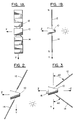
- Figs. 1a and 1b illustrate a typical 3-axis stabilized spacecraft 10 with solar panels 12 and 14 extending along a Y axis (north and south direction).
- the X axis is the roll axis
- the Y axis is the pitch axis
- the Z axis is the yaw axis.
- the Z axis nominally points to the center of the Earth.
- the solar array panels 12 and 14 are preferably positioned so that a line drawn through the sun is normal to the plane of the solar array panels.
- the solar array panels 12 and 14 are tilted away from the principal moment of inertia axes (and orbital coordinate frame) as shown in Fig. 2.
- this tilting of the solar array panels 12 and 14 results in the generation of a gravity gradient torque upon the spacecraft 10, as is described below in Equations 1, 2 and 3.
- Equations Ixx, Iyy and Izz are the principal moments of inertia of the spacecraft 10 along the X, Y and Z axes, respectively, of the orbital coordinate frame.
- the inventor has determined that if the solar array panels 12 and 14 are oriented such that Iyy is made equal to Izz, the gravity gradient torque about the X axis (roll) becomes zero, regardless of the spacecraft body orientation in roll, pitch, or yaw. Similarly, if the solar array panels 12 and 14 are oriented such that Ixx is equal to Izz, there is no Y axis (pitch) gravity gradient torque. Finally, if the solar array panels 12 and 14 are oriented such that Ixx is equal to Iyy there is no Z axis (yaw) gravity gradient torque.
- the inventor has exploited these relationships in a novel manner so that by setting two of the spacecraft's principal moments of inertia equal to one another, the gravity gradient torque about the third axis is minimized.
- the presently preferred technique for varying the principal moments of inertia is to employ the solar array panels 12 and 14.
- Fig. 3 shows one inertia shaping configuration whereby the solar array panels are tilted towards the minus Z axis, thereby minimizing the difference between Izz and Iyy.
- the X axis (roll) gravity gradient torque is minimized.
- some desired vibration-sensitive activity can be accomplished, such as taking an image with an imaging system 16. After taking the image the solar array panels are reoriented back towards the normal sun-pointing configuration.
- the required angular deviation of the solar array panels 12 and 14 from a reference axis can be determined prior to launch from the mass and inertia distribution properties of the spacecraft. These mass parameters can be further refined after the spacecraft is placed in orbit by the use of conventional techniques.
- the predetermined angular deviation is not orbit dependent, but is instead a function of the spacecraft mass.
- the value of AD is approximately 46 degrees.
- the spacecraft inertia becomes C, where, by example, Commands to orient and re-orient the solar array panels 12 and 14 can be sent to the spacecraft 10 from a ground station prior to and after performing a desired vibration-sensitive operation.
- the spacecraft 10 can be programmed to automatically orient and re-orient the solar array panels 12 and 14 prior to and after performing the desired vibration-sensitive operation.
- a consideration in employing the teaching of this invention is the spacecraft power. That is, if the spacecraft 10 cannot tolerate a short duration loss of solar power, then orienting the solar panel arrays 12 and 14 to point away from the sun may not be acceptable. However, for periodic imaging purposes the spacecraft 10 can use, and often times requires the use of, power from on-board batteries during imaging. In this case temporarily pointing the solar array panels 12 and 14 away from the sun is not detrimental. The solar array panels 12 and 14 are returned then to their nominal sun-pointing configuration to recharge the batteries in preparation for taking the next image.
Landscapes
- Engineering & Computer Science (AREA)
- Remote Sensing (AREA)
- Aviation & Aerospace Engineering (AREA)
- Combustion & Propulsion (AREA)
- Radar, Positioning & Navigation (AREA)
- Chemical & Material Sciences (AREA)
- Automation & Control Theory (AREA)
- Life Sciences & Earth Sciences (AREA)
- Environmental & Geological Engineering (AREA)
- General Life Sciences & Earth Sciences (AREA)
- Geochemistry & Mineralogy (AREA)
- Geology (AREA)
- Photovoltaic Devices (AREA)
- Control Of Position, Course, Altitude, Or Attitude Of Moving Bodies (AREA)
Abstract
Description
- This invention relates generally to satellite stabilization and positioning systems.
- All spacecraft in Earth orbit are exposed to a gravitational field that weakens with distance from the Earth. This results in the formation of a gravity gradient across the spacecraft which manifests itself as a torque on the spacecraft. This torque is generally undesirable and must be compensated for by using on-board actuators (e.g., reaction wheels or thrusters). However, the use of these actuators will typically induce a vibration within the spacecraft.
- For those spacecraft carrying payloads that are sensitive to vibrations, such as imaging payloads, it is beneficial to minimize vibrations to the spacecraft body while still rejecting external disturbance torques. It can thus be appreciated that the avoidance of the use of vibration sources such as reaction wheels, thrusters and other actuators during vibration-sensitive imaging is a desirable goal. However, avoiding the use of these vibration sources is feasible only if the disturbance torques on the spacecraft are minimized before they have the opportunity to act upon the spacecraft.
- The present invention seeks to overcome the foregoing and other problems by a method for minimizing the effects of gravity gradient torques upon a spacecraft, thereby reducing or eliminating a requirement to employ actuators during vibration-sensitive periods of spacecraft operation.
- To achieve a minimization of gravity gradient torques on a spacecraft in Earth orbit this invention teaches a method for reorienting the spacecraft's solar array panels in order to modify the principal axes moments of inertia of the spacecraft. Also referred to herein as "inertia shaping", the method is performed, preferably, just before the start of a vibration-sensitive period of spacecraft operation. For example, the method may be performed just prior to obtaining an image with an on-board imaging system. After imaging is complete the solar array panels are oriented back to a nominal sun-pointing configuration. Flat panel solar arrays are provided with two axes of rotation to be effective for inertia shaping. The teaching of this invention is especially beneficial when the inertia of the solar array panels dominates that of the spacecraft; which is often the case with relatively small, high power low earth orbit (LEO) satellites.
- In accordance with this invention there is provided a method for operating an orbiting spacecraft. The method includes the steps of (a) changing a mass distribution of the spacecraft from a first mass distribution for setting a first principal moment of inertia of the spacecraft along a first axis approximately equal to a second principal moment of inertia of the spacecraft along a second axis, thereby minimizing a gravity gradient torque about a third axis; (b) performing a desired activity while the gravity gradient torque about the third axis is minimized; and (c) resetting the mass distribution back to the first mass distribution at a completion of the desired activity. The spacecraft includes a plurality of solar array panels, and the step of changing is accomplished by varying a position of at least two of the solar array panels away from a sun-pointing configuration.
- Also disclosed is a method for stabilizing an orbiting spacecraft. This method includes the steps of (a) altering a mass distribution of the spacecraft from a first mass distribution for setting a first principal moment of inertia of the spacecraft along a first axis to be greater than a second principal moment of inertia of the spacecraft along a second axis, thereby reversing a sign of a gravity gradient torque upon the spacecraft and resisting a rotation of the spacecraft about a third axis; (b) performing a desired activity while the sign of the gravity gradient torque is reversed; and (c) resetting the mass distribution back to the first mass distribution at a completion of the desired activity. The spacecraft includes a plurality of solar array panels, and the step of altering is accomplished by varying a position of at least two of the solar array panels away from a sun-pointing configuration.
- In order that the invention and its various other preferred features may be understood more easily, some embodiments thereof will now be described, by way of example only, with reference to the drawings in which:-
- Fig. 1a is a front view and Fig. 1b is a side view illustrating a three axis stabilized spacecraft with solar array panels extending in a north and south direction along a Y axis;
- Fig. 2 illustrates a spacecraft with solar array panels tilted to point to the sun when in an inclined orbit; and
- Fig. 3 illustrates a temporary reorientation of the spacecraft solar array panels, in accordance with this invention, to minimize a difference between two principal axes moments of inertia, thereby minimizing a gravity gradient about a third axis.
- Figs. 1a and 1b illustrate a typical 3-axis stabilized
spacecraft 10 withsolar panels solar array panels - In order to point towards the sun while in an inclined orbit, as is typically the case for a LEO satellite, the
solar array panels solar array panels spacecraft 10, as is described below in Equations 1, 2 and 3. In the Equations Ixx, Iyy and Izz are the principal moments of inertia of thespacecraft 10 along the X, Y and Z axes, respectively, of the orbital coordinate frame.
- The inventor has determined that if the
solar array panels solar array panels solar array panels - The inventor has exploited these relationships in a novel manner so that by setting two of the spacecraft's principal moments of inertia equal to one another, the gravity gradient torque about the third axis is minimized. The presently preferred technique for varying the principal moments of inertia is to employ the
solar array panels - Fig. 3 shows one inertia shaping configuration whereby the solar array panels are tilted towards the minus Z axis, thereby minimizing the difference between Izz and Iyy. In this configuration, and in accordance with this invention, the X axis (roll) gravity gradient torque is minimized. During the time that the undesirable torque is minimized some desired vibration-sensitive activity can be accomplished, such as taking an image with an
imaging system 16. After taking the image the solar array panels are reoriented back towards the normal sun-pointing configuration. - It should be noted that if the solar array panels are tilted past the point where two of the spacecraft's principal moments of inertia are made equal to one another such that, by example, Iyy becomes greater than Izz, the sign of the gravity gradient torque is reversed and thus acts on the spacecraft in a stabilizing manner, thereby resisting a rotation of the spacecraft about the X axis. During this time a desired activity can be performed, such as taking an image or performing a communication function, after which the solar array panels are reoriented back to their normal sun-pointing configuration. Similarly, if Ixx is made greater than Izz, the gravity gradient torque resists rotations about the y axis.
- The required angular deviation of the
solar array panels - As an example, and referring to the case of Fig. 3 where it is desired to minimize the gravity gradient torque about the roll (x) axis; for a LEO spacecraft having a nominal moment of inertia of A and which includes two solar array panels each with a moment of inertia of B, the value of AD is approximately 46 degrees. With AD equal to 46 degrees the spacecraft inertia becomes C, where, by example,

Commands to orient and re-orient thesolar array panels spacecraft 10 from a ground station prior to and after performing a desired vibration-sensitive operation. Alternatively, thespacecraft 10 can be programmed to automatically orient and re-orient thesolar array panels - A consideration in employing the teaching of this invention is the spacecraft power. That is, if the
spacecraft 10 cannot tolerate a short duration loss of solar power, then orienting thesolar panel arrays spacecraft 10 can use, and often times requires the use of, power from on-board batteries during imaging. In this case temporarily pointing thesolar array panels solar array panels - While the invention has been particularly shown and described with respect to a preferred embodiment thereof, it will be understood by those skilled in the art that changes in form and details may be made therein without departing from the scope and spirit of the invention.
Claims (8)
- A method for operating an orbiting spacecraft, comprising the steps of:
changing a mass distribution of the spacecraft from a first mass distribution for setting a first principal moment of inertia of the spacecraft along a first axis approximately equal to a second principal moment of inertia of the spacecraft along a second axis, thereby minimizing a gravity gradient torque about a third axis;
performing a desired activity while the gravity gradient torque about the third axis is minimized; and
resetting the mass distribution back to the first mass distribution at a completion of the desired activity; wherein
the spacecraft includes a plurality of solar array panels, and wherein the step of changing is accomplished by varying a position of at least two of the solar array panels away from a sun-pointing configuration. - A method for operating a three axis stabilized orbiting spacecraft of a type that includes a plurality of solar array panels, the orbiting spacecraft having principal moments of inertia Ixx, Iyy and Izz along X, Y and Z axes, respectively, of an orbital coordinate frame, comprising the steps of:
changing a mass distribution of the spacecraft from a first mass distribution by varying an angular position of at least two of the solar array panels away from a sun-pointing configuration for setting one of a pair of Ixx and Iyy, Iyy and Izz, and Ixx and Izz approximately equal to one another, thereby minimizing a gravity gradient torque about a third axis that is not an axis associated with the pair of principal moments of inertia that are approximately equalized; and
performing a desired activity while the gravity gradient torque about the third axis is minimized. - A method as set forth in claim 2 wherein the step of changing is initiated by a command generated external to the spacecraft.
- A method as set forth in claim 2 wherein the step of changing is initiated by a command generated internal to the spacecraft.
- A method as set forth in claim 2 wherein the step of changing includes a step of rotating the at least two solar array panels through at least two degrees of rotational freedom.
- A method as set forth in claim 2 and further including a step of resetting the mass distribution back to the first mass distribution at a completion of the desired activity.
- A method as set forth in claim 2 wherein the step of performing a desired activity includes a step of taking an image with an imaging device that is carried by the spacecraft.
- A method for stabilizing an orbiting spacecraft, comprising the steps of:
altering a mass distribution of the spacecraft from a first mass distribution for setting a first principal moment of inertia of the spacecraft along a first axis to be greater than a second principal moment of inertia of the spacecraft along a second axis, thereby reversing a sign of a gravity gradient torque upon the spacecraft and resisting a rotation of the spacecraft about a third axis;
performing a desired activity while the sign of the gravity gradient torque is reversed; and
resetting the mass distribution back to the first mass distribution at a completion of the desired activity; wherein
the spacecraft includes a plurality of solar array panels, and wherein the step of altering is accomplished by varying a position of at least two of the solar array panels away from a sun-pointing configuration.
Applications Claiming Priority (2)
| Application Number | Priority Date | Filing Date | Title |
|---|---|---|---|
| US349950 | 1994-12-06 | ||
| US08/349,950 US5669586A (en) | 1994-12-06 | 1994-12-06 | Satellite gravity gradient compensation using on-orbit solar array reorientation |
Publications (3)
| Publication Number | Publication Date |
|---|---|
| EP0716365A2 true EP0716365A2 (en) | 1996-06-12 |
| EP0716365A3 EP0716365A3 (en) | 1996-12-27 |
| EP0716365B1 EP0716365B1 (en) | 2001-10-31 |
Family
ID=23374662
Family Applications (1)
| Application Number | Title | Priority Date | Filing Date |
|---|---|---|---|
| EP95308858A Expired - Lifetime EP0716365B1 (en) | 1994-12-06 | 1995-12-06 | Satellite gravity gradient compensation using on-orbit solar array reorientation |
Country Status (4)
| Country | Link |
|---|---|
| US (1) | US5669586A (en) |
| EP (1) | EP0716365B1 (en) |
| DE (1) | DE69523542T2 (en) |
| RU (1) | RU2180643C2 (en) |
Cited By (6)
| Publication number | Priority date | Publication date | Assignee | Title |
|---|---|---|---|---|
| FR2836450A1 (en) * | 2002-02-25 | 2003-08-29 | Centre Nat Etd Spatiales | SPACE VEHICLE AND METHOD FOR DRIVING SUCH A VEHICLE |
| WO2013002673A1 (en) * | 2011-06-30 | 2013-01-03 | Федеральное Государственное Бюджетное Образовательное Учреждение Высшего Профессионального Образования "Московский Государственный Технический Университет Имени Н.Э.Баумана" (Мгту Им. Н.Э.Баумана) | Method for reorientating and controlling the thrust of a rotating spacecraft with a solar sail |
| FR3032182A1 (en) * | 2015-02-03 | 2016-08-05 | Airbus Defence & Space Sas | SATELLITE DESORBITATION SYSTEM |
| EP3147223A1 (en) * | 2015-09-25 | 2017-03-29 | Thales | Deployable assembly |
| EP3170753A1 (en) * | 2015-11-13 | 2017-05-24 | The Boeing Company | Energy efficient satellite maneuvering |
| RU2685948C1 (en) * | 2018-04-02 | 2019-04-23 | ООО "Инжиниринговый центр микроспутниковых компетенций" | Method of microsatellite spatial orientation |
Families Citing this family (19)
| Publication number | Priority date | Publication date | Assignee | Title |
|---|---|---|---|---|
| US6070833A (en) * | 1998-04-09 | 2000-06-06 | Hughes Electronics Corporation | Methods for reducing solar array power variations while managing the system influences of operating with off-pointed solar wings |
| US6381520B1 (en) * | 2000-07-10 | 2002-04-30 | Space Systems/Loral, Inc. | Sun seeking solar array control system and method |
| US6481671B1 (en) | 2000-08-14 | 2002-11-19 | Ball Aerospace & Technologies Corp. | Spacecraft sunshield for use in performing solar torque balancing |
| RU2271968C2 (en) * | 2004-03-30 | 2006-03-20 | Закрытое акционерное общество "Конструкторское бюро "Полет" (ЗАО КБ "Полет") | Spacecraft with power supply units |
| RU2281890C1 (en) * | 2005-01-11 | 2006-08-20 | Центральный научно-исследовательский и опытно-конструкторский институт робототехники и кибернетики (ЦНИИ РТК) | Engine of spacecraft orientation and stabilization system |
| FR2955313B1 (en) * | 2010-01-19 | 2012-11-16 | Thales Sa | METHOD AND DEVICE FOR OPTIMIZING THE MASS OF A SATELLITE |
| RU2457159C2 (en) * | 2010-08-30 | 2012-07-27 | Открытое акционерное общество "Ракетно-космическая корпорация "Энергия" имени С.П. Королева" | Method of uniaxial orientation of elongated space vehicle |
| RU2457158C2 (en) * | 2010-09-22 | 2012-07-27 | Открытое акционерное общество "Ракетно-космическая корпорация "Энергия" имени С.П. Королева" | Method for space vehicle with fixed panels of solar batteries orientation control during experiments on orbits with maximum eclipse period |
| US9815575B2 (en) * | 2012-09-14 | 2017-11-14 | The Boeing Company | On-orbit reconfigurable solar array |
| RU2535979C2 (en) * | 2012-12-04 | 2014-12-20 | Открытое акционерное общество "Информационные спутниковые системы" имени академика М.Ф. Решетнёва" | Navigation satellite orientation system |
| RU2562904C1 (en) * | 2014-02-06 | 2015-09-10 | Открытое акционерное общество "Ракетно-космическая корпорация "Энергия" имени С.П. Королева" | Method of controlling orientation of spacecraft with fixed solar panels when conducting experiments |
| RU2562903C1 (en) * | 2014-02-06 | 2015-09-10 | Открытое акционерное общество "Ракетно-космическая корпорация "Энергия" имени С.П. Королева" | Method of controlling orientation of spacecraft with fixed solar panels when conducting experiments on orbits with maximum duration of eclipse period |
| RU2569999C2 (en) * | 2014-04-29 | 2015-12-10 | Акционерное общество "Информационные спутниковые системы" имени академика М.Ф. Решетнёва" | Navigation satellite orientation method |
| RU2594057C1 (en) * | 2015-02-02 | 2016-08-10 | Открытое акционерное общество "Ракетно-космическая корпорация "Энергия" имени С.П. Королева" | Method for uniaxial orientation of spacecraft with elongated shape |
| RU2594056C1 (en) * | 2015-02-02 | 2016-08-10 | Открытое акционерное общество "Ракетно-космическая корпорация "Энергия" имени С.П. Королева" | Method for uniaxial orientation of spacecraft with elongated shape |
| RU2594054C1 (en) * | 2015-02-02 | 2016-08-10 | Открытое акционерное общество "Ракетно-космическая корпорация "Энергия" имени С.П. Королева" | Method for uniaxial orientation of spacecraft with elongated shape |
| US12214910B2 (en) | 2019-06-17 | 2025-02-04 | The Board Of Trustees Of The University Of Illinois | Multifunctional structures for attitude control |
| WO2024186574A1 (en) * | 2023-03-03 | 2024-09-12 | The Board Of Trustees Of The University Of Illinois | Object design using multifunctional structures for attitude control |
| JPWO2025239432A1 (en) * | 2024-05-17 | 2025-11-20 |
Family Cites Families (26)
| Publication number | Priority date | Publication date | Assignee | Title |
|---|---|---|---|---|
| US3168263A (en) * | 1961-11-20 | 1965-02-02 | Gen Dynamics Corp | Gravity gradient satellite orientation system |
| US3268183A (en) * | 1963-12-12 | 1966-08-23 | Etkin Bernard | Passive stabilization of an earth's satellite |
| US3270984A (en) * | 1963-12-13 | 1966-09-06 | Goodyear Aerospace Corp | Gravity gradient satellite damping device |
| US3427623A (en) * | 1965-04-22 | 1969-02-11 | Joseph C Yater | Communication satellite |
| US3429525A (en) * | 1965-09-24 | 1969-02-25 | Westinghouse Electric Corp | Satellite orientation apparatus |
| US3386686A (en) * | 1967-01-19 | 1968-06-04 | Nasa Usa | Station keeping of a gravity-gradient stabilized satellite |
| US3519222A (en) * | 1967-01-27 | 1970-07-07 | Goodyear Aerospace Corp | Augmented gravity gradient satellite stabilization system |
| US3640487A (en) * | 1967-07-13 | 1972-02-08 | Gen Electric | Vertical orientation device |
| US3768756A (en) * | 1967-09-21 | 1973-10-30 | Westinghouse Electric Corp | Commandable satellite attitude control apparatus |
| US3582016A (en) * | 1967-10-03 | 1971-06-01 | Bernard C Sherman | Satellite attitude control mechanism and method |
| US3560642A (en) * | 1967-10-13 | 1971-02-02 | Us Navy | Television satellite system |
| US3601338A (en) * | 1967-11-17 | 1971-08-24 | Tokyo Shibaura Electric Co | Apparatus for controlling the attitude of a satellite |
| US3516622A (en) * | 1968-02-05 | 1970-06-23 | Gen Electric | Longitude keeper |
| US3567155A (en) * | 1968-12-20 | 1971-03-02 | James A Gatlin | Gravity gradient attitude control system |
| US3582019A (en) * | 1969-03-24 | 1971-06-01 | Vincent L Pisacane | Rotor for satellite stabilization |
| US3635425A (en) * | 1969-10-01 | 1972-01-18 | Us Navy | Deployment method for a telescoping solar array |
| US3582020A (en) * | 1969-12-01 | 1971-06-01 | Gen Dynamics Corp | Gravity gradient satellite orientation system for high pointing accuracy |
| US3698661A (en) * | 1970-10-07 | 1972-10-17 | Us Navy | Controllable hysteresis damping |
| US4097010A (en) * | 1975-10-08 | 1978-06-27 | Smithsonian Institution | Satellite connected by means of a long tether to a powered spacecraft |
| US4684084A (en) * | 1984-05-29 | 1987-08-04 | Rca Corporation | Spacecraft structure with symmetrical mass center and asymmetrical deployable appendages |
| US4728061A (en) * | 1985-03-20 | 1988-03-01 | Space Industries, Inc. | Spacecraft operable in two alternative flight modes |
| US4834325A (en) * | 1985-03-20 | 1989-05-30 | Space Industries, Inc. | Modular spacecraft system |
| US4757964A (en) * | 1986-07-17 | 1988-07-19 | Hughes Aircraft Company | Method for controlling the attitude of a spinning body in orbit |
| US4807835A (en) * | 1987-04-10 | 1989-02-28 | Ithaco, Inc. | Spacecraft attitude stabilization system |
| FR2669887B1 (en) * | 1990-11-30 | 1995-06-02 | Aerospatiale | METHOD FOR CONTROLLING THE ATTITUDE IN TANGAGE OF A SATELLITE THANKS TO THE SOLAR RADIATION PRESSURE AND SATELLITE SUITABLE FOR ITS IMPLEMENTATION. |
| US5310144A (en) * | 1992-07-06 | 1994-05-10 | Hughes Aircraft Company | Method and apparatus for satellite torque balancing |
-
1994
- 1994-12-06 US US08/349,950 patent/US5669586A/en not_active Expired - Fee Related
-
1995
- 1995-11-30 RU RU95121445/28A patent/RU2180643C2/en not_active IP Right Cessation
- 1995-12-06 EP EP95308858A patent/EP0716365B1/en not_active Expired - Lifetime
- 1995-12-06 DE DE69523542T patent/DE69523542T2/en not_active Expired - Fee Related
Cited By (16)
| Publication number | Priority date | Publication date | Assignee | Title |
|---|---|---|---|---|
| FR2836450A1 (en) * | 2002-02-25 | 2003-08-29 | Centre Nat Etd Spatiales | SPACE VEHICLE AND METHOD FOR DRIVING SUCH A VEHICLE |
| WO2013002673A1 (en) * | 2011-06-30 | 2013-01-03 | Федеральное Государственное Бюджетное Образовательное Учреждение Высшего Профессионального Образования "Московский Государственный Технический Университет Имени Н.Э.Баумана" (Мгту Им. Н.Э.Баумана) | Method for reorientating and controlling the thrust of a rotating spacecraft with a solar sail |
| RU2480387C2 (en) * | 2011-06-30 | 2013-04-27 | Государственное Образовательное Учреждение Высшего Профессионального Образования "Московский Государственный Технический Университет Имени Н.Э. Баумана" | Method of light-sail spacecraft reorientation and thrust control |
| EA023850B1 (en) * | 2011-06-30 | 2016-07-29 | Федеральное государственное бюджетное образовательное учреждение высшего профессионального образования "Московский государственный технический университет имени Н.Э. Баумана (МГТУ им. Н.Э. Баумана) | Method for reorientating and controlling thrust of rotating spacecraft with solar sail |
| FR3032182A1 (en) * | 2015-02-03 | 2016-08-05 | Airbus Defence & Space Sas | SATELLITE DESORBITATION SYSTEM |
| WO2016124593A1 (en) * | 2015-02-03 | 2016-08-11 | Airbus Defence And Space Sas | Satellite deorbiting system |
| US10723490B2 (en) | 2015-02-03 | 2020-07-28 | Arianegroup Sas | Satellite deorbiting system |
| US10207823B2 (en) | 2015-09-25 | 2019-02-19 | Thales | Deployable assembly |
| EP3147223A1 (en) * | 2015-09-25 | 2017-03-29 | Thales | Deployable assembly |
| FR3041608A1 (en) * | 2015-09-25 | 2017-03-31 | Thales Sa | DEPLOYABLE ASSEMBLY |
| EP3170753A1 (en) * | 2015-11-13 | 2017-05-24 | The Boeing Company | Energy efficient satellite maneuvering |
| US10377513B2 (en) | 2015-11-13 | 2019-08-13 | The Boeing Company | Energy efficient satellite maneuvering |
| US10407185B2 (en) | 2015-11-13 | 2019-09-10 | The Boeing Company | Energy efficient satellite maneuvering |
| US10005568B2 (en) | 2015-11-13 | 2018-06-26 | The Boeing Company | Energy efficient satellite maneuvering |
| US10882640B2 (en) | 2015-11-13 | 2021-01-05 | The Boeing Company | Energy efficient satellite maneuvering |
| RU2685948C1 (en) * | 2018-04-02 | 2019-04-23 | ООО "Инжиниринговый центр микроспутниковых компетенций" | Method of microsatellite spatial orientation |
Also Published As
| Publication number | Publication date |
|---|---|
| RU2180643C2 (en) | 2002-03-20 |
| EP0716365A3 (en) | 1996-12-27 |
| US5669586A (en) | 1997-09-23 |
| DE69523542T2 (en) | 2002-07-11 |
| DE69523542D1 (en) | 2001-12-06 |
| EP0716365B1 (en) | 2001-10-31 |
Similar Documents
| Publication | Publication Date | Title |
|---|---|---|
| US5669586A (en) | Satellite gravity gradient compensation using on-orbit solar array reorientation | |
| US6296207B1 (en) | Combined stationkeeping and momentum management | |
| US6032904A (en) | Multiple usage thruster mounting configuration | |
| EP0434861B1 (en) | Attitude pointing error correction system and method for geosynchronous satellites | |
| US9573703B2 (en) | Propulsion system for controlling the orbit and controlling the attitude of a satellite | |
| EP0922635B1 (en) | Fuel efficient methods for satellite stationkeeping and momentum dumping | |
| EP0781706A2 (en) | Systematic vectored thrust calibration method for satellite momentum control | |
| US6637701B1 (en) | Gimbaled ion thruster arrangement for high efficiency stationkeeping | |
| EP1059232A2 (en) | An orbit raising system and method for geosynchronous satellites | |
| EP0356602B1 (en) | Method of orienting a synchronous satellite | |
| CA2040463A1 (en) | Spacecraft earth-pointing attitude acquisition method | |
| US6053455A (en) | Spacecraft attitude control system using low thrust thrusters | |
| EP0654403A1 (en) | Method and apparatus for a satellite station keeping | |
| GB2122965A (en) | Station-keeping using solar sailing | |
| EP0195553A2 (en) | Spacecraft operable in two alternative flight modes | |
| US6076773A (en) | Spin-stabilized spacecraft and methods | |
| US12263962B2 (en) | Momentum wheels and reaction wheels for objects in space | |
| US6042058A (en) | Stationkeeping and momentum-dumping thruster systems and methods | |
| EP1227037B1 (en) | Thruster systems for spacecraft station changing, station keeping and momentum dumping | |
| JPH09328100A (en) | Single axis correction for orbital tilt | |
| EP1428755B1 (en) | Method and apparatus for solar tacking momentum maintenance in long-duration deployment of a large reflector | |
| US5957411A (en) | Method using double thruster firings to deadbeat flexible solar array structural oscillations | |
| JP3043671B2 (en) | How to place satellites in the same location | |
| US6648274B1 (en) | Virtual reaction wheel array | |
| US5646847A (en) | Universal thruster selection logic for spacecraft attitude control |
Legal Events
| Date | Code | Title | Description |
|---|---|---|---|
| PUAI | Public reference made under article 153(3) epc to a published international application that has entered the european phase |
Free format text: ORIGINAL CODE: 0009012 |
|
| AK | Designated contracting states |
Kind code of ref document: A2 Designated state(s): DE FR GB IT |
|
| PUAL | Search report despatched |
Free format text: ORIGINAL CODE: 0009013 |
|
| AK | Designated contracting states |
Kind code of ref document: A3 Designated state(s): DE FR GB IT |
|
| 17P | Request for examination filed |
Effective date: 19970117 |
|
| 17Q | First examination report despatched |
Effective date: 19991019 |
|
| RAP3 | Party data changed (applicant data changed or rights of an application transferred) |
Owner name: SPACE SYSTEMS / LORAL, INC. |
|
| GRAG | Despatch of communication of intention to grant |
Free format text: ORIGINAL CODE: EPIDOS AGRA |
|
| GRAG | Despatch of communication of intention to grant |
Free format text: ORIGINAL CODE: EPIDOS AGRA |
|
| GRAH | Despatch of communication of intention to grant a patent |
Free format text: ORIGINAL CODE: EPIDOS IGRA |
|
| GRAH | Despatch of communication of intention to grant a patent |
Free format text: ORIGINAL CODE: EPIDOS IGRA |
|
| GRAA | (expected) grant |
Free format text: ORIGINAL CODE: 0009210 |
|
| AK | Designated contracting states |
Kind code of ref document: B1 Designated state(s): DE FR GB IT |
|
| REF | Corresponds to: |
Ref document number: 69523542 Country of ref document: DE Date of ref document: 20011206 |
|
| REG | Reference to a national code |
Ref country code: GB Ref legal event code: IF02 |
|
| ET | Fr: translation filed | ||
| PLBE | No opposition filed within time limit |
Free format text: ORIGINAL CODE: 0009261 |
|
| STAA | Information on the status of an ep patent application or granted ep patent |
Free format text: STATUS: NO OPPOSITION FILED WITHIN TIME LIMIT |
|
| 26N | No opposition filed | ||
| PGFP | Annual fee paid to national office [announced via postgrant information from national office to epo] |
Ref country code: FR Payment date: 20021119 Year of fee payment: 8 |
|
| PGFP | Annual fee paid to national office [announced via postgrant information from national office to epo] |
Ref country code: GB Payment date: 20021127 Year of fee payment: 8 |
|
| PGFP | Annual fee paid to national office [announced via postgrant information from national office to epo] |
Ref country code: DE Payment date: 20021230 Year of fee payment: 8 |
|
| PG25 | Lapsed in a contracting state [announced via postgrant information from national office to epo] |
Ref country code: GB Free format text: LAPSE BECAUSE OF NON-PAYMENT OF DUE FEES Effective date: 20031206 |
|
| PG25 | Lapsed in a contracting state [announced via postgrant information from national office to epo] |
Ref country code: DE Free format text: LAPSE BECAUSE OF NON-PAYMENT OF DUE FEES Effective date: 20040701 |
|
| GBPC | Gb: european patent ceased through non-payment of renewal fee |
Effective date: 20031206 |
|
| PG25 | Lapsed in a contracting state [announced via postgrant information from national office to epo] |
Ref country code: FR Free format text: LAPSE BECAUSE OF NON-PAYMENT OF DUE FEES Effective date: 20040831 |
|
| REG | Reference to a national code |
Ref country code: FR Ref legal event code: ST |
|
| PG25 | Lapsed in a contracting state [announced via postgrant information from national office to epo] |
Ref country code: IT Free format text: LAPSE BECAUSE OF NON-PAYMENT OF DUE FEES;WARNING: LAPSES OF ITALIAN PATENTS WITH EFFECTIVE DATE BEFORE 2007 MAY HAVE OCCURRED AT ANY TIME BEFORE 2007. THE CORRECT EFFECTIVE DATE MAY BE DIFFERENT FROM THE ONE RECORDED. Effective date: 20051206 |