EP3147047A1 - Appareil de production d'une pièce tridimensionnelle avec un meilleur écoulement de gaz - Google Patents
Appareil de production d'une pièce tridimensionnelle avec un meilleur écoulement de gaz Download PDFInfo
- Publication number
- EP3147047A1 EP3147047A1 EP15186889.0A EP15186889A EP3147047A1 EP 3147047 A1 EP3147047 A1 EP 3147047A1 EP 15186889 A EP15186889 A EP 15186889A EP 3147047 A1 EP3147047 A1 EP 3147047A1
- Authority
- EP
- European Patent Office
- Prior art keywords
- process chamber
- gas
- gas inlet
- pressure equalization
- carrier
- Prior art date
- Legal status (The legal status is an assumption and is not a legal conclusion. Google has not performed a legal analysis and makes no representation as to the accuracy of the status listed.)
- Granted
Links
- 238000000034 method Methods 0.000 claims abstract description 199
- 230000005540 biological transmission Effects 0.000 claims abstract description 60
- 239000000843 powder Substances 0.000 claims abstract description 56
- 239000002994 raw material Substances 0.000 claims abstract description 43
- 230000005855 radiation Effects 0.000 claims abstract description 41
- 239000002245 particle Substances 0.000 claims abstract description 34
- 230000001678 irradiating effect Effects 0.000 claims abstract description 11
- 239000000654 additive Substances 0.000 claims abstract description 8
- 230000000996 additive effect Effects 0.000 claims abstract description 8
- 238000010276 construction Methods 0.000 claims abstract description 8
- 238000007599 discharging Methods 0.000 claims abstract description 4
- 238000011144 upstream manufacturing Methods 0.000 claims description 17
- 238000004519 manufacturing process Methods 0.000 claims description 3
- 239000007789 gas Substances 0.000 description 259
- 230000001681 protective effect Effects 0.000 description 16
- 239000010410 layer Substances 0.000 description 14
- 239000000779 smoke Substances 0.000 description 11
- 238000003466 welding Methods 0.000 description 11
- 239000012535 impurity Substances 0.000 description 10
- 230000003287 optical effect Effects 0.000 description 8
- 239000000463 material Substances 0.000 description 7
- XKRFYHLGVUSROY-UHFFFAOYSA-N Argon Chemical compound [Ar] XKRFYHLGVUSROY-UHFFFAOYSA-N 0.000 description 6
- IJGRMHOSHXDMSA-UHFFFAOYSA-N Atomic nitrogen Chemical compound N#N IJGRMHOSHXDMSA-UHFFFAOYSA-N 0.000 description 4
- 239000011261 inert gas Substances 0.000 description 4
- 230000000630 rising effect Effects 0.000 description 4
- 229910052786 argon Inorganic materials 0.000 description 3
- 239000000969 carrier Substances 0.000 description 3
- -1 for example Substances 0.000 description 3
- 239000000919 ceramic Substances 0.000 description 2
- 238000004320 controlled atmosphere Methods 0.000 description 2
- 230000008021 deposition Effects 0.000 description 2
- 238000007499 fusion processing Methods 0.000 description 2
- 239000011521 glass Substances 0.000 description 2
- 239000011796 hollow space material Substances 0.000 description 2
- 230000008018 melting Effects 0.000 description 2
- 238000002844 melting Methods 0.000 description 2
- 229910052757 nitrogen Inorganic materials 0.000 description 2
- 230000003134 recirculating effect Effects 0.000 description 2
- 229910052769 Ytterbium Inorganic materials 0.000 description 1
- 238000010521 absorption reaction Methods 0.000 description 1
- 238000006243 chemical reaction Methods 0.000 description 1
- 238000004140 cleaning Methods 0.000 description 1
- 238000009826 distribution Methods 0.000 description 1
- 239000000835 fiber Substances 0.000 description 1
- 230000004927 fusion Effects 0.000 description 1
- 238000010438 heat treatment Methods 0.000 description 1
- 229910001092 metal group alloy Inorganic materials 0.000 description 1
- 238000007500 overflow downdraw method Methods 0.000 description 1
- 238000007254 oxidation reaction Methods 0.000 description 1
- 230000000149 penetrating effect Effects 0.000 description 1
- 239000002861 polymer material Substances 0.000 description 1
- 238000002360 preparation method Methods 0.000 description 1
- 238000000926 separation method Methods 0.000 description 1
- 238000005245 sintering Methods 0.000 description 1
- 239000002344 surface layer Substances 0.000 description 1
- NAWDYIZEMPQZHO-UHFFFAOYSA-N ytterbium Chemical compound [Yb] NAWDYIZEMPQZHO-UHFFFAOYSA-N 0.000 description 1
Images


Classifications
-
- B—PERFORMING OPERATIONS; TRANSPORTING
- B23—MACHINE TOOLS; METAL-WORKING NOT OTHERWISE PROVIDED FOR
- B23K—SOLDERING OR UNSOLDERING; WELDING; CLADDING OR PLATING BY SOLDERING OR WELDING; CUTTING BY APPLYING HEAT LOCALLY, e.g. FLAME CUTTING; WORKING BY LASER BEAM
- B23K26/00—Working by laser beam, e.g. welding, cutting or boring
- B23K26/12—Working by laser beam, e.g. welding, cutting or boring in a special atmosphere, e.g. in an enclosure
- B23K26/123—Working by laser beam, e.g. welding, cutting or boring in a special atmosphere, e.g. in an enclosure in an atmosphere of particular gases
-
- B—PERFORMING OPERATIONS; TRANSPORTING
- B22—CASTING; POWDER METALLURGY
- B22F—WORKING METALLIC POWDER; MANUFACTURE OF ARTICLES FROM METALLIC POWDER; MAKING METALLIC POWDER; APPARATUS OR DEVICES SPECIALLY ADAPTED FOR METALLIC POWDER
- B22F10/00—Additive manufacturing of workpieces or articles from metallic powder
- B22F10/20—Direct sintering or melting
- B22F10/28—Powder bed fusion, e.g. selective laser melting [SLM] or electron beam melting [EBM]
-
- B—PERFORMING OPERATIONS; TRANSPORTING
- B22—CASTING; POWDER METALLURGY
- B22F—WORKING METALLIC POWDER; MANUFACTURE OF ARTICLES FROM METALLIC POWDER; MAKING METALLIC POWDER; APPARATUS OR DEVICES SPECIALLY ADAPTED FOR METALLIC POWDER
- B22F12/00—Apparatus or devices specially adapted for additive manufacturing; Auxiliary means for additive manufacturing; Combinations of additive manufacturing apparatus or devices with other processing apparatus or devices
- B22F12/70—Gas flow means
-
- B—PERFORMING OPERATIONS; TRANSPORTING
- B22—CASTING; POWDER METALLURGY
- B22F—WORKING METALLIC POWDER; MANUFACTURE OF ARTICLES FROM METALLIC POWDER; MAKING METALLIC POWDER; APPARATUS OR DEVICES SPECIALLY ADAPTED FOR METALLIC POWDER
- B22F3/00—Manufacture of workpieces or articles from metallic powder characterised by the manner of compacting or sintering; Apparatus specially adapted therefor ; Presses and furnaces
- B22F3/003—Apparatus, e.g. furnaces
-
- B—PERFORMING OPERATIONS; TRANSPORTING
- B23—MACHINE TOOLS; METAL-WORKING NOT OTHERWISE PROVIDED FOR
- B23K—SOLDERING OR UNSOLDERING; WELDING; CLADDING OR PLATING BY SOLDERING OR WELDING; CUTTING BY APPLYING HEAT LOCALLY, e.g. FLAME CUTTING; WORKING BY LASER BEAM
- B23K26/00—Working by laser beam, e.g. welding, cutting or boring
- B23K26/12—Working by laser beam, e.g. welding, cutting or boring in a special atmosphere, e.g. in an enclosure
-
- B—PERFORMING OPERATIONS; TRANSPORTING
- B23—MACHINE TOOLS; METAL-WORKING NOT OTHERWISE PROVIDED FOR
- B23K—SOLDERING OR UNSOLDERING; WELDING; CLADDING OR PLATING BY SOLDERING OR WELDING; CUTTING BY APPLYING HEAT LOCALLY, e.g. FLAME CUTTING; WORKING BY LASER BEAM
- B23K26/00—Working by laser beam, e.g. welding, cutting or boring
- B23K26/14—Working by laser beam, e.g. welding, cutting or boring using a fluid stream, e.g. a jet of gas, in conjunction with the laser beam; Nozzles therefor
- B23K26/142—Working by laser beam, e.g. welding, cutting or boring using a fluid stream, e.g. a jet of gas, in conjunction with the laser beam; Nozzles therefor for the removal of by-products
-
- B—PERFORMING OPERATIONS; TRANSPORTING
- B23—MACHINE TOOLS; METAL-WORKING NOT OTHERWISE PROVIDED FOR
- B23K—SOLDERING OR UNSOLDERING; WELDING; CLADDING OR PLATING BY SOLDERING OR WELDING; CUTTING BY APPLYING HEAT LOCALLY, e.g. FLAME CUTTING; WORKING BY LASER BEAM
- B23K26/00—Working by laser beam, e.g. welding, cutting or boring
- B23K26/34—Laser welding for purposes other than joining
- B23K26/342—Build-up welding
-
- B—PERFORMING OPERATIONS; TRANSPORTING
- B28—WORKING CEMENT, CLAY, OR STONE
- B28B—SHAPING CLAY OR OTHER CERAMIC COMPOSITIONS; SHAPING SLAG; SHAPING MIXTURES CONTAINING CEMENTITIOUS MATERIAL, e.g. PLASTER
- B28B1/00—Producing shaped prefabricated articles from the material
- B28B1/001—Rapid manufacturing of 3D objects by additive depositing, agglomerating or laminating of material
-
- B—PERFORMING OPERATIONS; TRANSPORTING
- B29—WORKING OF PLASTICS; WORKING OF SUBSTANCES IN A PLASTIC STATE IN GENERAL
- B29C—SHAPING OR JOINING OF PLASTICS; SHAPING OF MATERIAL IN A PLASTIC STATE, NOT OTHERWISE PROVIDED FOR; AFTER-TREATMENT OF THE SHAPED PRODUCTS, e.g. REPAIRING
- B29C64/00—Additive manufacturing, i.e. manufacturing of three-dimensional [3D] objects by additive deposition, additive agglomeration or additive layering, e.g. by 3D printing, stereolithography or selective laser sintering
- B29C64/10—Processes of additive manufacturing
- B29C64/141—Processes of additive manufacturing using only solid materials
- B29C64/153—Processes of additive manufacturing using only solid materials using layers of powder being selectively joined, e.g. by selective laser sintering or melting
-
- B—PERFORMING OPERATIONS; TRANSPORTING
- B29—WORKING OF PLASTICS; WORKING OF SUBSTANCES IN A PLASTIC STATE IN GENERAL
- B29C—SHAPING OR JOINING OF PLASTICS; SHAPING OF MATERIAL IN A PLASTIC STATE, NOT OTHERWISE PROVIDED FOR; AFTER-TREATMENT OF THE SHAPED PRODUCTS, e.g. REPAIRING
- B29C64/00—Additive manufacturing, i.e. manufacturing of three-dimensional [3D] objects by additive deposition, additive agglomeration or additive layering, e.g. by 3D printing, stereolithography or selective laser sintering
- B29C64/20—Apparatus for additive manufacturing; Details thereof or accessories therefor
-
- B—PERFORMING OPERATIONS; TRANSPORTING
- B29—WORKING OF PLASTICS; WORKING OF SUBSTANCES IN A PLASTIC STATE IN GENERAL
- B29C—SHAPING OR JOINING OF PLASTICS; SHAPING OF MATERIAL IN A PLASTIC STATE, NOT OTHERWISE PROVIDED FOR; AFTER-TREATMENT OF THE SHAPED PRODUCTS, e.g. REPAIRING
- B29C64/00—Additive manufacturing, i.e. manufacturing of three-dimensional [3D] objects by additive deposition, additive agglomeration or additive layering, e.g. by 3D printing, stereolithography or selective laser sintering
- B29C64/30—Auxiliary operations or equipment
- B29C64/35—Cleaning
-
- B—PERFORMING OPERATIONS; TRANSPORTING
- B29—WORKING OF PLASTICS; WORKING OF SUBSTANCES IN A PLASTIC STATE IN GENERAL
- B29C—SHAPING OR JOINING OF PLASTICS; SHAPING OF MATERIAL IN A PLASTIC STATE, NOT OTHERWISE PROVIDED FOR; AFTER-TREATMENT OF THE SHAPED PRODUCTS, e.g. REPAIRING
- B29C64/00—Additive manufacturing, i.e. manufacturing of three-dimensional [3D] objects by additive deposition, additive agglomeration or additive layering, e.g. by 3D printing, stereolithography or selective laser sintering
- B29C64/30—Auxiliary operations or equipment
- B29C64/357—Recycling
-
- B—PERFORMING OPERATIONS; TRANSPORTING
- B29—WORKING OF PLASTICS; WORKING OF SUBSTANCES IN A PLASTIC STATE IN GENERAL
- B29C—SHAPING OR JOINING OF PLASTICS; SHAPING OF MATERIAL IN A PLASTIC STATE, NOT OTHERWISE PROVIDED FOR; AFTER-TREATMENT OF THE SHAPED PRODUCTS, e.g. REPAIRING
- B29C64/00—Additive manufacturing, i.e. manufacturing of three-dimensional [3D] objects by additive deposition, additive agglomeration or additive layering, e.g. by 3D printing, stereolithography or selective laser sintering
- B29C64/30—Auxiliary operations or equipment
- B29C64/364—Conditioning of environment
- B29C64/371—Conditioning of environment using an environment other than air, e.g. inert gas
-
- B—PERFORMING OPERATIONS; TRANSPORTING
- B33—ADDITIVE MANUFACTURING TECHNOLOGY
- B33Y—ADDITIVE MANUFACTURING, i.e. MANUFACTURING OF THREE-DIMENSIONAL [3-D] OBJECTS BY ADDITIVE DEPOSITION, ADDITIVE AGGLOMERATION OR ADDITIVE LAYERING, e.g. BY 3-D PRINTING, STEREOLITHOGRAPHY OR SELECTIVE LASER SINTERING
- B33Y10/00—Processes of additive manufacturing
-
- B—PERFORMING OPERATIONS; TRANSPORTING
- B33—ADDITIVE MANUFACTURING TECHNOLOGY
- B33Y—ADDITIVE MANUFACTURING, i.e. MANUFACTURING OF THREE-DIMENSIONAL [3-D] OBJECTS BY ADDITIVE DEPOSITION, ADDITIVE AGGLOMERATION OR ADDITIVE LAYERING, e.g. BY 3-D PRINTING, STEREOLITHOGRAPHY OR SELECTIVE LASER SINTERING
- B33Y30/00—Apparatus for additive manufacturing; Details thereof or accessories therefor
-
- B—PERFORMING OPERATIONS; TRANSPORTING
- B33—ADDITIVE MANUFACTURING TECHNOLOGY
- B33Y—ADDITIVE MANUFACTURING, i.e. MANUFACTURING OF THREE-DIMENSIONAL [3-D] OBJECTS BY ADDITIVE DEPOSITION, ADDITIVE AGGLOMERATION OR ADDITIVE LAYERING, e.g. BY 3-D PRINTING, STEREOLITHOGRAPHY OR SELECTIVE LASER SINTERING
- B33Y40/00—Auxiliary operations or equipment, e.g. for material handling
-
- B—PERFORMING OPERATIONS; TRANSPORTING
- B22—CASTING; POWDER METALLURGY
- B22F—WORKING METALLIC POWDER; MANUFACTURE OF ARTICLES FROM METALLIC POWDER; MAKING METALLIC POWDER; APPARATUS OR DEVICES SPECIALLY ADAPTED FOR METALLIC POWDER
- B22F10/00—Additive manufacturing of workpieces or articles from metallic powder
- B22F10/30—Process control
- B22F10/32—Process control of the atmosphere, e.g. composition or pressure in a building chamber
- B22F10/322—Process control of the atmosphere, e.g. composition or pressure in a building chamber of the gas flow, e.g. rate or direction
-
- B—PERFORMING OPERATIONS; TRANSPORTING
- B22—CASTING; POWDER METALLURGY
- B22F—WORKING METALLIC POWDER; MANUFACTURE OF ARTICLES FROM METALLIC POWDER; MAKING METALLIC POWDER; APPARATUS OR DEVICES SPECIALLY ADAPTED FOR METALLIC POWDER
- B22F10/00—Additive manufacturing of workpieces or articles from metallic powder
- B22F10/70—Recycling
- B22F10/77—Recycling of gas
-
- B—PERFORMING OPERATIONS; TRANSPORTING
- B22—CASTING; POWDER METALLURGY
- B22F—WORKING METALLIC POWDER; MANUFACTURE OF ARTICLES FROM METALLIC POWDER; MAKING METALLIC POWDER; APPARATUS OR DEVICES SPECIALLY ADAPTED FOR METALLIC POWDER
- B22F2998/00—Supplementary information concerning processes or compositions relating to powder metallurgy
- B22F2998/10—Processes characterised by the sequence of their steps
-
- Y—GENERAL TAGGING OF NEW TECHNOLOGICAL DEVELOPMENTS; GENERAL TAGGING OF CROSS-SECTIONAL TECHNOLOGIES SPANNING OVER SEVERAL SECTIONS OF THE IPC; TECHNICAL SUBJECTS COVERED BY FORMER USPC CROSS-REFERENCE ART COLLECTIONS [XRACs] AND DIGESTS
- Y02—TECHNOLOGIES OR APPLICATIONS FOR MITIGATION OR ADAPTATION AGAINST CLIMATE CHANGE
- Y02P—CLIMATE CHANGE MITIGATION TECHNOLOGIES IN THE PRODUCTION OR PROCESSING OF GOODS
- Y02P10/00—Technologies related to metal processing
- Y02P10/25—Process efficiency
Definitions
- the present invention relates to an apparatus for producing a three-dimensional work piece by irradiating layers of a raw material powder with electromagnetic or particle radiation.
- the invention further relates to a method of operating such an apparatus.
- Powder bed fusion is an additive layering process by which pulverulent, in particular metallic and/or ceramic raw materials can be processed to three-dimensional work pieces of complex shapes.
- a raw material powder layer is applied onto a carrier and subjected to electromagnetic or particle radiation in dependence on the desired geometry of the work piece that is to be produced.
- the electromagnetic or particle radiation penetrating into the powder layer causes heating and consequently melting or sintering of the raw material particles.
- Further raw material powder layers are then applied successively to the layer on the carrier that has already been subjected to radiation treatment, until the work piece has the desired shape and size.
- Powder bed fusion methods can be used in particular for the production of prototypes, tools, replacement parts or medical prostheses on the basis of CAD data.
- the prior art apparatus comprises a process chamber which accommodates a plurality of carriers for the shaped bodies to be manufactured.
- a powder layer preparation system comprises a powder reservoir holder that can be moved to and fro across the carriers in order to apply a raw material powder to be irradiated with a laser beam onto the carriers.
- the process chamber is provided with a protective gas inlet and a protective gas outlet which are connected to a protective gas circuit. Via the protective gas inlet, a protective gas such as, for example, Argon is supplied to the process chamber in order to establish a protective gas atmosphere within the process chamber. Via the protective gas outlet, protective gas which, upon flowing through the process chamber, is loaded with particulate impurities such as, for example, residual raw material powder particles and welding smoke particles is withdrawn from the process chamber.
- welding smoke generated in a powder bed fusion process upon irradiating and hence melting a raw material powder may contaminate the interior of a process chamber and also components of an irradiation system, such as, for example, a lens or window through which a radiation beam is directed into the process chamber.
- an irradiation system such as, for example, a lens or window through which a radiation beam is directed into the process chamber.
- a gradually increasing part of the radiation energy emitted by the irradiation system may be absorbed by deposited welding smoke condensate material.
- EP 1 839 781 A2 therefore proposes to provide a protective gas conveying system with means for generating and maintaining a separation zone in the form of a protective gas flow layer between a product built-up zone and an upper wall of the process chamber which is specified as being almost impenetrable for welding smoke.
- the protective gas conveying system comprises an elongated nozzle which extends in a horizontal direction in a side wall of the process chamber. Via the nozzle, a protective gas, which is supplied to the nozzle at an elevated pressure by means of a compressor, is supplied to the process chamber in such a manner that a substantially laminar protective gas flow is generated.
- An outlet opening through which the protective gas is withdrawn from the process chamber by means of a blower is provided in a further side wall of the process chamber opposite to the nozzle.
- the present invention is directed at the object of providing an apparatus for producing a three-dimensional work piece by irradiating layers of a raw material powder with electromagnetic or particle radiation, wherein stable operating conditions during the time of operation can be maintained and thus high-quality work pieces can be produced. Further, the invention is directed at the object of providing a method of operating an apparatus of this kind.
- An apparatus for producing a three dimensional work piece comprises a process chamber accommodating a carrier for receiving a raw material powder.
- the carrier may be a rigidly fixed carrier having a surface onto which the raw material powder is applied in order to be subjected to electromagnetic or particle radiation.
- the carrier is designed to be displaceable in vertical direction, so that, with increasing construction height of a work piece, as it is built up in layers from the raw material powder, the carrier can be moved downwards in the vertical direction.
- the raw material powder applied onto the carrier within the process chamber is preferably a metallic powder, in particular a metal alloy powder, but may also be a ceramic powder or a powder containing different materials.
- the powder may have any suitable particle size or particle size distribution. It is, however, preferable to process powders of particle sizes ⁇ 100 ⁇ m.
- the apparatus further comprises an irradiation device for selectively irradiating electromagnetic or particle radiation onto the raw material powder on the carrier in order to produce a work piece made of said raw material powder by an additive layer construction method.
- the raw material powder applied onto the carrier may be subjected to electromagnetic or particle radiation in a site-selective manner in dependence on the desired geometry of the work piece that is to be produced.
- the irradiation device may comprise a radiation beam source, in particular a laser beam source, and additionally may comprise an optical unit for guiding and/or processing a radiation beam emitted by the radiation beam source.
- the optical unit may comprise optical elements such an object lens, in particular and f-theta lens, and a scanner unit, the scanner unit preferably comprising a diffractive optical element and a deflection mirror.
- the apparatus is provided with a first gas inlet for supplying gas to the process chamber.
- the gas supplied by the first gas inlet may be an inert gas such as, for example, Argon, Nitrogen or the like.
- the process chamber may be sealable against the ambient atmosphere, in order to be able to maintain a controlled atmosphere therein.
- the controlled atmosphere may be an inert gas atmosphere in order to prevent undesired chemical reactions, in particular, oxidation reactions.
- the apparatus comprises a gas outlet for discharging gas from the process chamber.
- the first gas inlet and the gas outlet are configured and arranged in such a manner that a first gas flow across the carrier is generated.
- the first gas flow preferably is directed substantially parallel to the carrier so as to ensure that particulate impurities generated in the process chamber upon irradiating the raw material powder on the carrier with electromagnetic or particle radiation are purged from the process chamber by the first gas flow guided through the process chamber from the first gas inlet to the gas outlet.
- the first gas inlet and the gas outlet may be arranged in the region of opposing side walls of the process chamber.
- the gas outlet may be connected to a gas discharge line which in turn is connected to a first gas supply line connected to the first gas inlet so as to define a recirculation system to which gas exiting the process chamber via the gas outlet may be recirculated into the process chamber via the first gas inlet.
- a suitable filter arrangement may be provided in the recirculation system.
- the apparatus further comprises a transmission element which allows the transmission of the electromagnetic or particle radiation emitted by the irradiation device into the process chamber.
- the transmission element may, for example, be designed in the form of a window.
- the transmission element may comprise or consist of an optical element, in particular a lens, of the irradiation device.
- the transmission element may be arranged in the region of wall of the process chamber, in particular in the region of a top wall of the process chamber.
- the transmission element is arranged in a region above a center of the carrier.
- the transmission element may be integrated into a wall, in particular a top wall of the process chamber.
- the material of the transmission element may be selected in dependence on the type of the radiation emitted by the irradiation device in order to ensure the desired transmissibility of the transmission element for the electromagnetic or particle radiation emitted by the irradiation device. Further, the material of the transmission element should be selected in such a manner that the transmission element is capable of withstanding the thermal loads acting on the transmission element during operation of the apparatus for producing a three dimensional work piece.
- the transmission element may be made of a glass material or a suitable polymer material. If desired, the transmission element, in the region of a surface facing the interior of the process chamber, may be provided with a surface layer which minimizes the adhesion and deposition of welding smoke condensate onto the surface of the transmission element.
- the apparatus comprises a second gas inlet for supplying gas to the process chamber.
- the same gas, in particular inert gas is supplied to the process chamber via the first and the second gas inlet.
- different gases are directed into the process chamber via the first and the second gas inlet.
- the second gas inlet may be connected to a second gas supply line adapted to be flown through with the gas to be supplied into the process chamber via the second gas inlet.
- the second gas supply line may be connected to the first gas supply line which serves to supply gas to the first gas inlet. It is, however, also conceivable that the second gas supply line is designed independent from the first gas supply line and is, for example, directly connected to a gas source.
- the second gas inlet is configured and arranged in such a manner that a second gas flow in a direction facing away from the transmission element is generated.
- the second gas inlet may be arranged in the region of at least one wall of the process chamber.
- the second gas inlet is arranged adjacent to the transmission element, i.e. in a preferred embodiment of the apparatus, the second gas inlet is arranged at least in the region of the wall of the process chamber which also accommodates the transmission element.
- the second gas inlet preferably also is arranged at least in the region of the top wall of the process chamber.
- the second gas flow exiting the second gas inlet may flow away from the transmission element in a direction substantially perpendicular to a wall of the process chamber accommodating the transmission element. Additionally or alternatively thereto, the second gas flow may flow in the direction of the carrier and preferably substantially perpendicular thereto.
- particulate impurities for example welding smoke rising from the raw material powder applied onto the carrier upon being irradiated with electromagnetic or particle radiation or powder particles, are either prevented from reaching the transmission element or at least guided away from the transmission element.
- the second gas flow thus constitutes a protective gas flow which protects the transmission element from being contaminated by particulate impurities present in the process chamber.
- the apparatus for producing a three-dimensional work piece may further comprise a control unit which may be designed in the form of an electronic control unit and which may be adapted to control the supply of gas to the process chamber in such a manner that a volume flow of gas into the process chamber via the second gas inlet is larger than a volume flow of gas into the process chamber via the first gas inlet.
- a control unit which may be designed in the form of an electronic control unit and which may be adapted to control the supply of gas to the process chamber in such a manner that a volume flow of gas into the process chamber via the second gas inlet is larger than a volume flow of gas into the process chamber via the first gas inlet.
- the second gas inlet may comprise a plurality of gas inlets openings.
- the process chamber can be provided with the desired high inlet volume flow of gas at a relatively low gas inlet pressure.
- the plurality of gas inlet openings of the second gas inlet are configured and arranged so as to define a second gas inlet area.
- the second gas inlet area defined by the gas inlet openings of the second gas inlet may be arranged substantially parallel to the carrier so as to allow the generation of the second gas flow in the direction of the carrier and substantially perpendicular thereto.
- the size of the second gas inlet area may be substantially equal to or larger than a surface area of the carrier.
- the second gas inlet area comprises a first portion which is arranged in the region of the top wall of the process chamber and a second portion which is arranged in the region of a side wall of the process chamber.
- the second portion of the second gas inlet area may be arranged in the region of a side wall of the process chamber which also accommodates the first gas inlet.
- the apparatus may further comprise a pressure equalization container which may be arranged in a gas supply line, i.e. the second gas supply line, upstream of the second gas inlet.
- a pressure equalization container which may be arranged in a gas supply line, i.e. the second gas supply line, upstream of the second gas inlet.
- upstream refers to the direction of flow of gas through the gas supply line, i.e. the second gas supply line, connected to the second gas inlet.
- the pressure equalization container serves to compensate for pressure differences occurring in the gas supply line upstream of the second gas inlet and in the process chamber, for example due to temperature differences developing during operation of the apparatus.
- gas can be supplied to the process chamber via the second gas inlet in a particularly uniform manner.
- the pressure equalization container may be integrated into a wall of the process chamber.
- the pressure equalization container may be defined by a hollow space formed in a wall of the process chamber.
- the pressure equalization container then may be installed in the apparatus in a particularly space saving manner.
- the second gas inlet may be arranged in a wall of the pressure equalization container which faces the process chamber. Gas to be supplied to the process chamber via the second gas inlet then may easily be directed from the pressure equalization container into the process chamber.
- the transmission element may be arranged in the wall of the pressure equalization container which faces the process chamber.
- a further transmission element which may be designed similar or equal to the transmission element may be arranged in a wall of the pressure equalization container which faces away from the process chamber and which separates the pressure equalization container from the irradiation device. Electromagnetic or particle radiation emitted from the irradiation device then may be directed through the pressure equalization container into the process chamber.
- the pressure equalization container may comprise a first portion which is integrated into the top wall of the process chamber and a second portion which is integrated into a side wall of the process chamber.
- the second portion of the pressure equalization container may be arranged in the region of a side wall of the process chamber which also accommodates the first gas inlet.
- This configuration of a pressure equalization container is particularly advantageous in combination with a second gas inlet area comprising a first and a second portion as described above.
- the pressure equalization container may comprise further portions which may be arranged in the region of further side walls of the process chamber in order to adapt the design of the pressure equalization container to the design of the second gas inlet area.
- the apparatus may be provided with a further pressure equalization container which is arranged in a further gas supply line, i.e. the first gas supply line, upstream of the first gas inlet.
- a further pressure equalization container which is arranged in a further gas supply line, i.e. the first gas supply line, upstream of the first gas inlet.
- upstream refers to the direction of flow of gas through the further gas supply line, i.e. the first gas supply line, connected to the first gas inlet.
- the gas to be supplied to the process chamber via the first gas inlet, prior to entering the process chamber then is directed into the further pressure equalization container which serves to compensate for pressure differences occurring in the gas supply line upstream of the first gas inlet and in the process chamber, for example due to temperature differences developing during operation of the apparatus.
- the presence of the further pressure equalization container allows gas to be supplied to the process chamber via the first gas inlet in a particularly uniform manner.
- a layer of raw material powder is applied onto a carrier accommodated in a process chamber.
- Gas is supplied to the process chamber via a first gas inlet.
- Gas is discharged from the process chamber via a gas outlet.
- the first gas inlet and the gas outlet are configured and arranged in such a manner that the first gas flow across the carrier is generated.
- the method further comprises the step of selectively irradiating electromagnetic or particle radiation onto the raw material powder on the carrier by means of the irradiation device in order to produce a work piece made of said raw material powder by an additive layer construction method.
- the electromagnetic or particle radiation emitted by the irradiation device is transmitted into the process chamber via a transmission element.
- Gas is supplied to the process chamber via a second gas inlet.
- the second gas inlet is configured and arranged in such a manner that a second gas flow in a direction facing away from the transmission element is generated.
- the supply of gas to the process chamber is controlled in such a manner that a volume flow of gas into the process chamber via the second gas inlet is larger than a volume flow of gas into the process chamber via the first gas inlet.
- the second gas inlet may comprise a plurality of gas inlet openings which may be configured and arranged so as to define a second gas inlet area.
- the second gas inlet area preferably comprises a first portion which is arranged in the region of a top wall of the process chamber and a second portion which is arranged in the region of a side wall of the process chamber.
- the second portion of the second gas inlet area may be arranged in the region of a side wall of the process chamber which also accommodates the first gas inlet.
- the gas to be supplied to the process chamber via the second gas inlet may be directed through a pressure equalization container which may be arranged in a gas supply line connected to the second gas inlet, i.e. the second gas supply line, upstream of the second gas inlet.
- the pressure equalization container may be integrated into a wall of the process chamber.
- the second gas inlet may be arranged in a wall of pressure equalization container which faces the process chamber.
- the transmission element may be arranged in a wall of the pressure equalization container which faces the process chamber.
- the pressure equalization container may comprise a first portion which is integrated into a top wall of the process chamber and a second portion which is integrated into the side wall of the process chamber.
- the second portion of the pressure equalization container may be arranged in the region of a side wall of the process chamber which also accommodates the first gas inlet.
- Gas to be supplied to the process chamber via the first gas inlet may be directed through a further pressure equalization container.
- the further pressure equalization container may be arranged in a further gas supply line connected to the first gas inlet, i.e. the first gas supply line, upstream of the first gas inlet.
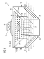
- Figures 1 and 2 show a first embodiment of an apparatus 10 for producing a three-dimensional work piece by an additive layering process.
- the apparatus 10 comprises a process chamber 12 accommodating a carrier 14 (see figure 2 ) for receiving a raw material powder.
- a powder application device (not shown) serves to apply the raw material powder onto the carrier 14.
- the carrier 14 is designed to be displaceable in a vertical direction so that, with increasing construction height of a work piece, as it is built up in layers from the raw material powder on the carrier 14, the carrier 14 can be moved downwards in the vertical direction.
- the apparatus 10 for producing a three-dimensional work piece further comprises an irradiation device 16 for selectively irradiating electromagnetic or particle radiation, in particular laser radiation onto the raw material powder applied onto the carrier 14 in order to produce a work piece made of said raw material powder by an additive layer construction method.
- the raw material powder on the carrier 14 may be subjected to electromagnetic or particle radiation in a site selective manner in dependence on the desired geometry of the component that is to be produced.
- the irradiation device 16 comprises a radiation source 18 which may comprise a diode pumped Ytterbium fibre laser emitting laser light at a wavelength of approximately 1070 to 1080 nm.
- the irradiation device 16 further comprises an optical unit 20 for guiding and processing a radiation beam emitted by the radiation source 18.
- the optical unit may comprise a beam expander for expanding the radiation beam, a scanner and an object lens.
- the optical unit may comprise a beam expander including a focusing optic and a scanner unit.
- the scanner unit may be designed in the form of a galvanometer scanner and the object lens may be an f-theta object lens.
- the process chamber 12 is sealed against the ambient atmosphere, i.e. against the environment surrounding the process chamber 12.
- the process chamber 12 is provided with a first gas inlet 22 for supplying gas from the gas source 23 to the process chamber 12.
- the gas supplied to the process chamber via the first gas inlet 22 may be an inert gas such as, for example, Argon, Nitrogen or the like. It is however also conceivable to supply the process chamber 12 with air via the first gas inlet 22.
- the gas is conveyed into the process chamber 12 via the first gas inlet 22 by means of a suitable conveying device such as, for example, a pump or a blower (not shown) which is arranged in a first gas supply line 24.
- Gas containing particulate impurities is discharged from the process chamber 12 via a gas outlet 26.
- the gas outlet 26 is connected to a gas discharge line 28 which in turn is connected to the first gas supply line 24 connected to the first gas inlet 22 so as to define a recirculation system to which gas exiting the process chamber 12 via the gas outlet 26 is recirculated into the process chamber 12 via the first gas inlet 22.
- a suitable filter arrangement (not shown) is provided in the recirculation system.
- the first gas inlet 22 and the gas outlet 26 are configured and arranged in such a manner that a first gas flow F1 across the carrier 14 is generated.
- the first gas flow F1 is directed substantially parallel to the carrier 14 so that particulate impurities generated in the process chamber 12 upon irradiating the raw material powder on the carrier 14 with electromagnetic or particle radiation are purged from the process chamber 12 by the first gas flow F1 guided through the process chamber 12 from the first gas inlet 22 to the gas outlet 26.
- this is achieved by arranging a slit-shaped first gas inlet 22 and a slit-shaped gas outlet 22 in the region of opposing side walls 30, 32 of the process chamber 12.
- the apparatus 10 further comprises a transmission element 34 which allows the transmission of the electromagnetic or particle radiation emitted by the irradiation device 16 into the process chamber 12.
- the transmission element 34 is designed in the form of a window made of glass or a polymeric material which is arranged in the region of a top wall 36 of the process chamber 12 above a center of the carrier 14.
- a radiation beam emitted by the irradiation device 16 can be guided through the transmission element 34 and across the carrier 14 as desired in dependence on the geometry of the work piece to be produced.
- the apparatus 10 comprises a second gas inlet 38 for supplying gas to the process chamber 12.
- the second gas inlet 38 is connected to a second gas supply line 40 which is flown through with the gas to be supplied into the process chamber 12 via the second gas inlet 38.
- the second gas supply line 40 is connected to the gas source 23.
- the same gas is supplied to the process chamber 12 via the first and the second gas inlet 22, 38.
- the second gas inlet 38 is configured and arranged in such a manner that a second gas flow F2 in a direction facing away from the transmission element 34 is generated.
- the second gas flow F2 is directed from the top wall 36 of the process chamber 12 which accommodates the transmission element 34 in the direction of the carrier 14 and substantially perpendicular to both the top wall 36 of the process chamber 12 and the carrier 14. In the embodiment of an apparatus 10 shown in the drawings, this is achieved by arranging the second gas inlet 38 in the region of the top wall 36 of the process chamber 12 adjacent to the transmission element 34.
- particulate impurities for example welding smoke rising from the raw material powder applied onto the carrier 14 upon being irradiated with electromagnetic or particle radiation or powder particles, are either prevented from reaching the transmission element 34 or at least guided away from the transmission element 34.
- the second gas flow F2 thus constitutes a protective gas flow which protects the transmission element 34 from being contaminated by particulate impurities present in the process chamber 12.
- the supply of gas to the process chamber 12, by means of a control unit 42, is controlled in such a manner that a volume flow of gas into the process chamber 12 via the second gas inlet 38 is larger than a volume flow of gas into the process chamber 12 via the first gas inlet 22.
- This control of the gas supply to the process chamber allows preventing the transmission element 34 from being contaminated in a particularly reliable manner.
- the second gas inlet 38 comprises a plurality of gas inlets openings 44.
- the process chamber 12 can be provided with the desired high inlet volume flow of gas through the second gas inlet 38 at a relatively low gas inlet pressure.
- the plurality of gas inlet openings 44 of the second gas inlet 38 are configured and arranged so as to define a second gas inlet area A which is arranged substantially parallel to the carrier 14 so as to allow the generation of the second gas flow F2 in the direction of the carrier 14 and substantially perpendicular thereto.
- the size of the second gas inlet area A is substantially equal to a surface area of the carrier 14 so that welding smoke rising from the raw material powder applied onto the carrier 14 upon being irradiated at any position on the carrier 14 is prevented from reaching and hence contaminating the transmission element 34.
- the apparatus 10 further comprises a pressure equalization container 46 which is arranged in the second gas supply line 40 upstream of the second gas inlet 38.
- the term "upstream" refers to the direction of flow of gas through the second gas supply line 40.
- the pressure equalization container 46 is integrated into a wall of the process chamber 12.
- the pressure equalization container 46 is integrated into the top wall 36 of the process chamber 12 and defined by a hollow space formed in the top wall 36 of the process chamber 12.
- the second gas inlet 38 is arranged in a wall 48 of the pressure equalization container 46 which faces the process chamber 12.
- the transmission element 34 is arranged in the wall 38 of the pressure equalization container 46 which faces the process chamber 12.
- a further transmission element 50 (see figure 2 ) which is designed equal to the transmission element 34 is arranged in a wall 52 of the pressure equalization container 46 which faces away from the process chamber 12 and which separates the pressure equalization container 46 from the irradiation device 16. Electromagnetic or particle radiation emitted from the irradiation device 16 thus can be directed through the pressure equalization container 46 into the process chamber 12.
- a second embodiment of an apparatus 10 which is shown in figure 3 differs from the apparatus 10 according to figures 1 and 2 in that the second gas inlet area A comprises a first portion A1 which is arranged in the region of the top wall 36 of the process chamber 12 and a second portion 8 to which is arranged in the region of the first side wall 30 of the process chamber 12.
- the second portion A2 of the second gas inlet area A is arranged in the region of the first side wall 30 of the process chamber 12 which also accommodates the first gas inlet 22.
- the size of the second gas inlet area A can be increased, allowing the supply of a particularly high volume flow of gas to the process chamber 12 via the second gas inlet 38 at a particularly low pressure.
- the pressure equalization container 46 comprises a first portion 46a which is integrated into the top wall 36 of the process chamber 12 and a second portion 46b which is integrated into the first side wall 30 of the process chamber 12.
- the second portion 46b of the pressure equalization container 46 is arranged in the region of the first side wall 30 of the process chamber 12 which also accommodates the first gas inlet 38.
- the structure and the function of the apparatus 10 according to figure 3 correspond to the structure and the function of the apparatus 10 depicted in figures 1 and 2 .
- a third embodiment of an apparatus 10 which is shown in figure 4 differs from the apparatus 10 according to figures 1 and 2 in that the apparatus 10 depicted in figure 4 is provided with a further pressure equalization container 54 which is arranged in the first gas supply line 24 upstream of the first gas inlet 22.
- the term "upstream" refers to the direction of flow of gas through the first gas supply line 24.
- the apparatus 10 for producing a three-dimensional work piece can be equipped with a further pressure equalization container 54.
Priority Applications (4)
| Application Number | Priority Date | Filing Date | Title |
|---|---|---|---|
| EP15186889.0A EP3147047B1 (fr) | 2015-09-25 | 2015-09-25 | Appareil de production d'une pièce tridimensionnelle avec un meilleur écoulement de gaz et méthode de production d'une pièce tridimensionnelle |
| US15/248,487 US10682701B2 (en) | 2015-09-25 | 2016-08-26 | Apparatus for producing a three-dimensional work piece with improved gas flow |
| JP2016182724A JP6284993B2 (ja) | 2015-09-25 | 2016-09-20 | 改善されたガス流を有する三次元加工物の製造装置 |
| CN201610847783.6A CN107008900B (zh) | 2015-09-25 | 2016-09-23 | 用于生产三维工件的设备和方法 |
Applications Claiming Priority (1)
| Application Number | Priority Date | Filing Date | Title |
|---|---|---|---|
| EP15186889.0A EP3147047B1 (fr) | 2015-09-25 | 2015-09-25 | Appareil de production d'une pièce tridimensionnelle avec un meilleur écoulement de gaz et méthode de production d'une pièce tridimensionnelle |
Publications (2)
| Publication Number | Publication Date |
|---|---|
| EP3147047A1 true EP3147047A1 (fr) | 2017-03-29 |
| EP3147047B1 EP3147047B1 (fr) | 2023-08-02 |
Family
ID=54330583
Family Applications (1)
| Application Number | Title | Priority Date | Filing Date |
|---|---|---|---|
| EP15186889.0A Active EP3147047B1 (fr) | 2015-09-25 | 2015-09-25 | Appareil de production d'une pièce tridimensionnelle avec un meilleur écoulement de gaz et méthode de production d'une pièce tridimensionnelle |
Country Status (4)
| Country | Link |
|---|---|
| US (1) | US10682701B2 (fr) |
| EP (1) | EP3147047B1 (fr) |
| JP (1) | JP6284993B2 (fr) |
| CN (1) | CN107008900B (fr) |
Cited By (18)
| Publication number | Priority date | Publication date | Assignee | Title |
|---|---|---|---|---|
| EP3290184A1 (fr) * | 2016-09-02 | 2018-03-07 | EOS GmbH Electro Optical Systems | Procédé et dispositif de fabrication additive d'un objet tridimensionnel |
| WO2018087088A1 (fr) * | 2016-11-10 | 2018-05-17 | Addup | Machine de fabrication additive a double peau |
| DE102016121490A1 (de) * | 2016-11-10 | 2018-05-17 | Trumpf Laser- Und Systemtechnik Gmbh | Homogene absaugung bei der generativen fertigung |
| DE102017104351A1 (de) * | 2017-03-02 | 2018-09-06 | Cl Schutzrechtsverwaltungs Gmbh | Vorrichtung zur additiven Herstellung dreidimensionaler Objekte |
| DE102017205027A1 (de) | 2017-03-24 | 2018-09-27 | SLM Solutions Group AG | Vorrichtung und Verfahren zum Herstellen von dreidimensionalen Werkstücken |
| DE102017122849A1 (de) * | 2017-10-02 | 2019-04-04 | Stefan Fischer | Fluidversorgungssystem für einen 3D-Drucker |
| EP3620245A1 (fr) * | 2018-09-07 | 2020-03-11 | EOS GmbH Electro Optical Systems | Procédé d'alimentation en courant pour un dispositif de fabrication additive |
| WO2020099852A1 (fr) | 2018-11-12 | 2020-05-22 | Renishaw Plc | Procédé d'identification d'événements anormaux dans la fabrication additive |
| WO2020121132A1 (fr) * | 2018-12-11 | 2020-06-18 | Io Tech Group Ltd. | Systèmes et procédés pour empêcher l'inhibition par l'oxygène d'une réaction de polymérisation initiée par la lumière dans un système d'impression 3d à l'aide d'un gaz inerte |
| CN111989177A (zh) * | 2018-04-09 | 2020-11-24 | 通用电气公司 | 用于增材制造流动控制装置的系统和方法 |
| WO2021249820A1 (fr) | 2020-06-10 | 2021-12-16 | Trumpf Laser- Und Systemtechnik Gmbh | Dispositif de fabrication à vaste circulation de gaz de dissipation |
| WO2022096668A1 (fr) | 2020-11-09 | 2022-05-12 | Trumpf Laser- Und Systemtechnik Gmbh | Procédé et dispositif destinés à la fabrication d'objets en 3d par consolidation sélective d'un matériau déposé en couches |
| WO2022096669A1 (fr) | 2020-11-09 | 2022-05-12 | Trumpf Laser- Und Systemtechnik Gmbh | Procédé et dispositif destinés à la fabrication d'objets en 3d par consolidation sélective d'un matériau déposé en couches |
| WO2022096670A1 (fr) | 2020-11-09 | 2022-05-12 | Trumpf Laser- Und Systemtechnik Gmbh | Dispositif d'aspiration destiné à aspirer un gaz de traitement contenu dans une chambre de traitement d'un dispositif et dispositif destiné à la fabrication d'objets tridimensionnels |
| CN114728341A (zh) * | 2019-11-14 | 2022-07-08 | 大阳日酸株式会社 | 层叠造型系统及层叠造型方法 |
| EP4046736A1 (fr) * | 2021-02-22 | 2022-08-24 | Linde GmbH | Dispositif et procédé de fabrication additive par dépôt direct d'énergie (ded) |
| WO2023067272A1 (fr) * | 2021-10-21 | 2023-04-27 | Compagnie Generale Des Etablissements Michelin | Rosace de répartition de fluide et utilisation de celle-ci pour contrôler l'atmosphère d'une imprimante 3d |
| WO2023195948A1 (fr) * | 2022-04-08 | 2023-10-12 | Estas Eksantrik Sanayi Ve Ticaret Anonim Sirketi | Mécanique d'écoulement de gaz pour imprimante métal avec procédé de frittage laser direct de métal |
Families Citing this family (34)
| Publication number | Priority date | Publication date | Assignee | Title |
|---|---|---|---|---|
| US9579851B2 (en) | 2013-03-22 | 2017-02-28 | Markforged, Inc. | Apparatus for fiber reinforced additive manufacturing |
| US10953609B1 (en) | 2013-03-22 | 2021-03-23 | Markforged, Inc. | Scanning print bed and part height in 3D printing |
| US9186848B2 (en) | 2013-03-22 | 2015-11-17 | Markforged, Inc. | Three dimensional printing of composite reinforced structures |
| US9156205B2 (en) | 2013-03-22 | 2015-10-13 | Markforged, Inc. | Three dimensional printer with composite filament fabrication |
| US11237542B2 (en) | 2013-03-22 | 2022-02-01 | Markforged, Inc. | Composite filament 3D printing using complementary reinforcement formations |
| US9126365B1 (en) | 2013-03-22 | 2015-09-08 | Markforged, Inc. | Methods for composite filament fabrication in three dimensional printing |
| CA3121870A1 (fr) | 2013-03-22 | 2014-09-25 | Markforged, Inc. | Impression tridimensionnelle |
| US9694544B2 (en) * | 2013-03-22 | 2017-07-04 | Markforged, Inc. | Methods for fiber reinforced additive manufacturing |
| US9186846B1 (en) | 2013-03-22 | 2015-11-17 | Markforged, Inc. | Methods for composite filament threading in three dimensional printing |
| EP3004435B1 (fr) | 2013-06-05 | 2018-08-08 | Markforged, Inc. | Procédés de fabrication d'additif renforcé de fibres |
| DE102016216678A1 (de) * | 2016-09-02 | 2018-03-08 | Eos Gmbh Electro Optical Systems | Verfahren und Vorrichtung zum generativen Herstellen eines dreidimensionalen Objekts |
| US20180178285A1 (en) * | 2016-12-23 | 2018-06-28 | General Electric Company | Method for controlling plume trajectories in additive manufacturing |
| USD893569S1 (en) * | 2017-08-09 | 2020-08-18 | General Electric Company | Nozzle for an additive manufacturing machine |
| US10821664B2 (en) | 2017-08-09 | 2020-11-03 | General Electric Company | Nozzle for additive manufacturing machine |
| JP6393873B1 (ja) * | 2017-09-05 | 2018-09-26 | 株式会社松浦機械製作所 | 三次元造形装置 |
| US20190099943A1 (en) * | 2017-10-03 | 2019-04-04 | General Electric Company | Additive manufacturing method and apparatus |
| TWI661927B (zh) * | 2017-10-12 | 2019-06-11 | 國家中山科學研究院 | 積層製造腔體 |
| CN111315511B (zh) * | 2017-11-10 | 2022-08-12 | 通用电气公司 | 增材制造机器的气流系统 |
| US11504909B2 (en) * | 2017-12-18 | 2022-11-22 | Honda Motor Co., Ltd. | 3-dimensional object-forming apparatus |
| EP3539695A1 (fr) | 2018-03-12 | 2019-09-18 | Renishaw PLC | Procédés et appareil de fabrication additive de lit de poudre |
| US20190322050A1 (en) * | 2018-04-19 | 2019-10-24 | General Electric Company | Additive manufacturing system and method |
| CN108422667B (zh) * | 2018-05-09 | 2023-10-31 | 苏州倍丰智能科技有限公司 | 保护气体供给系统 |
| US11426818B2 (en) | 2018-08-10 | 2022-08-30 | The Research Foundation for the State University | Additive manufacturing processes and additively manufactured products |
| US11020763B2 (en) * | 2018-08-21 | 2021-06-01 | General Electric Company | Spacer flow guide for partitioning build chamber of an additive manufacturing system |
| DE102018121136A1 (de) * | 2018-08-29 | 2020-03-05 | Eos Gmbh Electro Optical Systems | Schichtbauvorrichtung zur additiven Herstellung zumindest eines Bauteilbereichs eines Bauteils, Verfahren zum Betreiben einer solchen Schichtbauvorrichtung und Speichermedium |
| CN109351969B (zh) * | 2018-11-14 | 2021-02-19 | 浙江工贸职业技术学院 | 金属三维打印机 |
| CN109622962B (zh) * | 2018-12-28 | 2020-07-28 | 南京航空航天大学 | 一种多通道双循环气氛保护系统 |
| WO2020178220A1 (fr) * | 2019-03-04 | 2020-09-10 | SLM Solutions Group AG | Dispositif et procédé de production d'une pièce tridimensionnelle |
| CN109877320B (zh) * | 2019-03-15 | 2021-02-12 | 杨清萍 | 一种多料仓、压力可调型的3d打印系统及方法 |
| WO2020198050A1 (fr) * | 2019-03-22 | 2020-10-01 | Desktop Metal, Inc. | Environnement contrôlé pour fabrication additive |
| CN110126277A (zh) * | 2019-06-04 | 2019-08-16 | 无锡科技职业学院 | 一种可自动清理的3d打印机 |
| US11759861B2 (en) | 2021-04-16 | 2023-09-19 | General Electric Company | Additive manufacturing build units with process gas inertization systems |
| US11938539B2 (en) | 2021-04-16 | 2024-03-26 | General Electric Company | Additive manufacturing build units with process gas inertization systems |
| US20220347758A1 (en) * | 2021-07-29 | 2022-11-03 | Northrop Grumman Systems Corporation | Inlet manifold for a laminar gas flow in a laser powder bed fusion system |
Citations (6)
| Publication number | Priority date | Publication date | Assignee | Title |
|---|---|---|---|---|
| WO1992008592A1 (fr) * | 1990-11-09 | 1992-05-29 | Dtm Corporation | Flux de gaz regule pour frittage selectif au laser |
| EP0785838A1 (fr) * | 1995-08-16 | 1997-07-30 | EOS GmbH ELECTRO OPTICAL SYSTEMS DR. LANGER & PARTNER | Procede de production d'un objet en couche par frittage par laser |
| US6583379B1 (en) * | 1998-11-23 | 2003-06-24 | Fraunhofer-Gesellschaft zur Förderung der angewandten Forschung e.V. | Process chamber for selective laser fusion |
| EP1839781A2 (fr) | 2006-03-30 | 2007-10-03 | Matthias Fockele | Dispositif de fabrication d'objets par montage en couche à partir de matière première en poudre |
| EP1793979B1 (fr) | 2004-08-27 | 2009-02-11 | MTT Technologies GmbH | Dispositif pour realiser des corps moules |
| US20130101803A1 (en) * | 2011-10-25 | 2013-04-25 | Maik Grebe | Apparatus for avoiding deposits on optical components in the laser sintering process |
Family Cites Families (9)
| Publication number | Priority date | Publication date | Assignee | Title |
|---|---|---|---|---|
| JPS6027359Y2 (ja) * | 1980-09-30 | 1985-08-17 | 山崎電機工業株式会社 | 連続加熱炉における循環式急速冷却装置 |
| JPS58178436A (ja) | 1982-04-13 | 1983-10-19 | Akiyoshi Kinoshita | 文字入力装置 |
| CA2228765A1 (fr) | 1995-08-18 | 1997-02-27 | Dr. Rentschler Biotechnologie Gmbh | Compositions pharmaceutiques servant a l'inhibition competitive de la fixation d'un retrovirus sur le recepteur ifn et procede de diagnostic d'une infection a vih |
| DE29600707U1 (de) | 1996-01-17 | 1996-03-07 | Burgmann Dichtungswerk Feodor | Abdichtungsanordnung |
| US8373092B2 (en) * | 2008-04-09 | 2013-02-12 | The Boeing Company | Purge and sealant cap for selective laser sintering build frame |
| GB0813241D0 (en) | 2008-07-18 | 2008-08-27 | Mcp Tooling Technologies Ltd | Manufacturing apparatus and method |
| JP5761497B2 (ja) | 2011-03-22 | 2015-08-12 | 株式会社Ihi | 狭隘部異物除去装置 |
| JP5721886B1 (ja) * | 2014-06-20 | 2015-05-20 | 株式会社ソディック | 積層造形装置 |
| JP5721887B1 (ja) | 2014-06-20 | 2015-05-20 | 株式会社ソディック | 積層造形装置 |
-
2015
- 2015-09-25 EP EP15186889.0A patent/EP3147047B1/fr active Active
-
2016
- 2016-08-26 US US15/248,487 patent/US10682701B2/en active Active
- 2016-09-20 JP JP2016182724A patent/JP6284993B2/ja active Active
- 2016-09-23 CN CN201610847783.6A patent/CN107008900B/zh active Active
Patent Citations (6)
| Publication number | Priority date | Publication date | Assignee | Title |
|---|---|---|---|---|
| WO1992008592A1 (fr) * | 1990-11-09 | 1992-05-29 | Dtm Corporation | Flux de gaz regule pour frittage selectif au laser |
| EP0785838A1 (fr) * | 1995-08-16 | 1997-07-30 | EOS GmbH ELECTRO OPTICAL SYSTEMS DR. LANGER & PARTNER | Procede de production d'un objet en couche par frittage par laser |
| US6583379B1 (en) * | 1998-11-23 | 2003-06-24 | Fraunhofer-Gesellschaft zur Förderung der angewandten Forschung e.V. | Process chamber for selective laser fusion |
| EP1793979B1 (fr) | 2004-08-27 | 2009-02-11 | MTT Technologies GmbH | Dispositif pour realiser des corps moules |
| EP1839781A2 (fr) | 2006-03-30 | 2007-10-03 | Matthias Fockele | Dispositif de fabrication d'objets par montage en couche à partir de matière première en poudre |
| US20130101803A1 (en) * | 2011-10-25 | 2013-04-25 | Maik Grebe | Apparatus for avoiding deposits on optical components in the laser sintering process |
Cited By (43)
| Publication number | Priority date | Publication date | Assignee | Title |
|---|---|---|---|---|
| US11090869B2 (en) * | 2016-09-02 | 2021-08-17 | Eos Gmbh Electro Optical Systems | Method and apparatus for generatively manufacturing a three-dimensional object |
| DE102016216682A1 (de) * | 2016-09-02 | 2018-03-08 | Eos Gmbh Electro Optical Systems | Verfahren und Vorrichtung zum generativen Herstellen eines dreidimensionalen Objekts |
| US20180065303A1 (en) * | 2016-09-02 | 2018-03-08 | Eos Gmbh Electro Optical Systems | Method and Apparatus for Generatively Manufacturing a Three-Dimensional Object |
| EP3290184A1 (fr) * | 2016-09-02 | 2018-03-07 | EOS GmbH Electro Optical Systems | Procédé et dispositif de fabrication additive d'un objet tridimensionnel |
| EP3538294B1 (fr) * | 2016-11-10 | 2024-01-03 | AddUp | Machine de fabrication additive a double peau |
| US11072121B2 (en) | 2016-11-10 | 2021-07-27 | Addup | Double-skin additive manufacturing machine |
| US11167353B2 (en) | 2016-11-10 | 2021-11-09 | Trumpf Laser- Und Systemtechnik Gmbh | Homogeneous suction during additive manufacturing |
| DE102016121490A1 (de) * | 2016-11-10 | 2018-05-17 | Trumpf Laser- Und Systemtechnik Gmbh | Homogene absaugung bei der generativen fertigung |
| WO2018087088A1 (fr) * | 2016-11-10 | 2018-05-17 | Addup | Machine de fabrication additive a double peau |
| WO2018087251A1 (fr) | 2016-11-10 | 2018-05-17 | Trumpf Laser- Und Systemtechnik Gmbh | Aspiration homogène lors de la fabrication additive |
| EP3369570B1 (fr) | 2017-03-02 | 2021-08-25 | CL Schutzrechtsverwaltungs GmbH | Dispositif de fabrication additive d'objets tridimensionnels |
| US11103953B2 (en) | 2017-03-02 | 2021-08-31 | Concept Laser Gmbh | Device for additive production of three-dimensional objects |
| DE102017104351A1 (de) * | 2017-03-02 | 2018-09-06 | Cl Schutzrechtsverwaltungs Gmbh | Vorrichtung zur additiven Herstellung dreidimensionaler Objekte |
| DE102017205027A1 (de) | 2017-03-24 | 2018-09-27 | SLM Solutions Group AG | Vorrichtung und Verfahren zum Herstellen von dreidimensionalen Werkstücken |
| CN111433004A (zh) * | 2017-10-02 | 2020-07-17 | 库莫维斯有限公司 | 3d打印机的流体供应系统 |
| DE102017122849A1 (de) * | 2017-10-02 | 2019-04-04 | Stefan Fischer | Fluidversorgungssystem für einen 3D-Drucker |
| CN111989177A (zh) * | 2018-04-09 | 2020-11-24 | 通用电气公司 | 用于增材制造流动控制装置的系统和方法 |
| EP3620245A1 (fr) * | 2018-09-07 | 2020-03-11 | EOS GmbH Electro Optical Systems | Procédé d'alimentation en courant pour un dispositif de fabrication additive |
| US11504772B2 (en) | 2018-09-07 | 2022-11-22 | Eos Gmbh Electro Optical Systems | Method for providing a flow for an additive manufacturing device |
| WO2020099852A1 (fr) | 2018-11-12 | 2020-05-22 | Renishaw Plc | Procédé d'identification d'événements anormaux dans la fabrication additive |
| WO2020121132A1 (fr) * | 2018-12-11 | 2020-06-18 | Io Tech Group Ltd. | Systèmes et procédés pour empêcher l'inhibition par l'oxygène d'une réaction de polymérisation initiée par la lumière dans un système d'impression 3d à l'aide d'un gaz inerte |
| US11203154B2 (en) | 2018-12-11 | 2021-12-21 | Io Tech Group Ltd. | Systems and methods for preventing oxygen inhibition of a light-initiated polymerization reaction in a 3D printing system using inert gas |
| US11673328B2 (en) | 2018-12-11 | 2023-06-13 | Io Tech Group Ltd. | Methods for preventing oxygen inhibition of a light-initiated polymerization reaction in a 3D printing system using inert gas |
| CN113412186B (zh) * | 2018-12-11 | 2023-04-04 | Io技术集团公司 | 用于使用惰性气体防止在3d打印系统中光引发聚合反应的氧阻聚的系统和方法 |
| US11590701B2 (en) | 2018-12-11 | 2023-02-28 | Io Tech Group Ltd. | Systems for preventing oxygen inhibition of a light-initiated polymerization reaction in a 3D printing system using uniform planar surfaces |
| CN113412186A (zh) * | 2018-12-11 | 2021-09-17 | Io技术集团公司 | 用于使用惰性气体防止在3d打印系统中光引发聚合反应的氧阻聚的系统和方法 |
| EP3894181B1 (fr) * | 2018-12-11 | 2022-11-16 | IO Tech Group, Ltd. | Systèmes et procédés pour empêcher l'inhibition par l'oxygène d'une réaction de polymérisation initiée par la lumière dans un système d'impression 3d à l'aide d'un gaz inerte |
| US11453164B2 (en) | 2018-12-11 | 2022-09-27 | Io Tech Group Ltd. | Methods for preventing oxygen inhibition of a light-initiated polymerization reaction in a 3D printing system using uniform planar surfaces |
| CN114728341A (zh) * | 2019-11-14 | 2022-07-08 | 大阳日酸株式会社 | 层叠造型系统及层叠造型方法 |
| WO2021249820A1 (fr) | 2020-06-10 | 2021-12-16 | Trumpf Laser- Und Systemtechnik Gmbh | Dispositif de fabrication à vaste circulation de gaz de dissipation |
| DE102020115414A1 (de) | 2020-06-10 | 2021-12-16 | Trumpf Laser- Und Systemtechnik Gmbh | Fertigungsvorrichtung mit grossflächigem absenkgasstrom |
| DE102020129419A1 (de) | 2020-11-09 | 2022-05-12 | Trumpf Laser- Und Systemtechnik Gmbh | Verfahren und Vorrichtung zur Herstellung von dreidimensionalen Objekten durch selektives Verfestigen eines schichtweise aufgebrachten Aufbaumaterials |
| DE102020129416A1 (de) | 2020-11-09 | 2022-05-12 | Trumpf Laser- Und Systemtechnik Gmbh | Absaugvorrichtung zum Absaugen von Prozessgas aus einer Prozesskammer einer Vorrichtung sowie Vorrichtung zur Herstellung von dreidimensionalen Objekten |
| DE102020129413A1 (de) | 2020-11-09 | 2022-05-12 | Trumpf Laser- Und Systemtechnik Gmbh | Verfahren und Vorrichtung zur Herstellung von dreidimensionalen Objekten durch selektives Verfestigen eines schichtweise aufgebrachten Aufbaumaterials |
| WO2022096670A1 (fr) | 2020-11-09 | 2022-05-12 | Trumpf Laser- Und Systemtechnik Gmbh | Dispositif d'aspiration destiné à aspirer un gaz de traitement contenu dans une chambre de traitement d'un dispositif et dispositif destiné à la fabrication d'objets tridimensionnels |
| DE102020129416B4 (de) | 2020-11-09 | 2023-02-09 | Trumpf Laser- Und Systemtechnik Gmbh | Absaugvorrichtung zum Absaugen von Prozessgas aus einer Prozesskammer einer Vorrichtung sowie Vorrichtung zur Herstellung von dreidimensionalen Objekten |
| WO2022096669A1 (fr) | 2020-11-09 | 2022-05-12 | Trumpf Laser- Und Systemtechnik Gmbh | Procédé et dispositif destinés à la fabrication d'objets en 3d par consolidation sélective d'un matériau déposé en couches |
| WO2022096668A1 (fr) | 2020-11-09 | 2022-05-12 | Trumpf Laser- Und Systemtechnik Gmbh | Procédé et dispositif destinés à la fabrication d'objets en 3d par consolidation sélective d'un matériau déposé en couches |
| EP4046736A1 (fr) * | 2021-02-22 | 2022-08-24 | Linde GmbH | Dispositif et procédé de fabrication additive par dépôt direct d'énergie (ded) |
| WO2022174983A1 (fr) * | 2021-02-22 | 2022-08-25 | Linde Gmbh | Dispositif et procédé de fabrication additive par dépôt sous énergie concentrée (ded) |
| WO2023067272A1 (fr) * | 2021-10-21 | 2023-04-27 | Compagnie Generale Des Etablissements Michelin | Rosace de répartition de fluide et utilisation de celle-ci pour contrôler l'atmosphère d'une imprimante 3d |
| FR3128396A1 (fr) * | 2021-10-21 | 2023-04-28 | Compagnie Generale Des Etablissements Michelin | Rosace de répartition de fluide et utilisation de celle-ci pour contrôler l’atmosphère d’une imprimante 3d |
| WO2023195948A1 (fr) * | 2022-04-08 | 2023-10-12 | Estas Eksantrik Sanayi Ve Ticaret Anonim Sirketi | Mécanique d'écoulement de gaz pour imprimante métal avec procédé de frittage laser direct de métal |
Also Published As
| Publication number | Publication date |
|---|---|
| JP2017061745A (ja) | 2017-03-30 |
| US20170087635A1 (en) | 2017-03-30 |
| EP3147047B1 (fr) | 2023-08-02 |
| CN107008900B (zh) | 2019-08-13 |
| US10682701B2 (en) | 2020-06-16 |
| JP6284993B2 (ja) | 2018-02-28 |
| CN107008900A (zh) | 2017-08-04 |
Similar Documents
| Publication | Publication Date | Title |
|---|---|---|
| US10682701B2 (en) | Apparatus for producing a three-dimensional work piece with improved gas flow | |
| US11278965B2 (en) | Apparatus for producing a three-dimensional work piece with improved gas flow | |
| US9931789B2 (en) | Method and apparatus for producing a large three-dimensional work piece | |
| EP2952333B1 (fr) | Procédé et appareil de fabrication de pièces tridimensionnelles | |
| EP2992986A1 (fr) | Appareil de fabrication de pièces 3D par une méthode de fabrication additive comportant un dispositif de séchage | |
| EP2774703A1 (fr) | Appareil de production de pièces de travail sous pression élevée | |
| US20160059310A1 (en) | Apparatus for producing work pieces with an improved gas circuit | |
| US10252332B2 (en) | Powder processing arrangement and method for use in an apparatus for producing three-dimensional work pieces | |
| US20160144431A1 (en) | Powder circuit for use in an apparatus for producing three-dimensional work pieces | |
| JP6356177B2 (ja) | 積層造形装置 | |
| CN109550948B (zh) | 喷嘴以及层叠造型装置 | |
| CN111201099B (zh) | 制造三维工件的设备和方法 |
Legal Events
| Date | Code | Title | Description |
|---|---|---|---|
| PUAI | Public reference made under article 153(3) epc to a published international application that has entered the european phase |
Free format text: ORIGINAL CODE: 0009012 |
|
| STAA | Information on the status of an ep patent application or granted ep patent |
Free format text: STATUS: REQUEST FOR EXAMINATION WAS MADE |
|
| 17P | Request for examination filed |
Effective date: 20161128 |
|
| AK | Designated contracting states |
Kind code of ref document: A1 Designated state(s): AL AT BE BG CH CY CZ DE DK EE ES FI FR GB GR HR HU IE IS IT LI LT LU LV MC MK MT NL NO PL PT RO RS SE SI SK SM TR |
|
| AX | Request for extension of the european patent |
Extension state: BA ME |
|
| RAP1 | Party data changed (applicant data changed or rights of an application transferred) |
Owner name: SLM SOLUTIONS GROUP AG |
|
| STAA | Information on the status of an ep patent application or granted ep patent |
Free format text: STATUS: EXAMINATION IS IN PROGRESS |
|
| 17Q | First examination report despatched |
Effective date: 20180706 |
|
| RIN1 | Information on inventor provided before grant (corrected) |
Inventor name: SCHWARZE, DIETER Inventor name: WILKES, JAN Inventor name: KROL, TONI ADAM |
|
| GRAP | Despatch of communication of intention to grant a patent |
Free format text: ORIGINAL CODE: EPIDOSNIGR1 |
|
| STAA | Information on the status of an ep patent application or granted ep patent |
Free format text: STATUS: GRANT OF PATENT IS INTENDED |
|
| RIC1 | Information provided on ipc code assigned before grant |
Ipc: B23K 26/342 20140101ALI20191205BHEP Ipc: B22F 3/105 20060101AFI20191205BHEP Ipc: B29C 64/357 20170101ALI20191205BHEP Ipc: B29C 67/00 20170101ALI20191205BHEP Ipc: B29C 64/371 20170101ALI20191205BHEP Ipc: B33Y 10/00 20150101ALI20191205BHEP Ipc: B29C 64/153 20170101ALI20191205BHEP Ipc: B23K 26/142 20140101ALI20191205BHEP Ipc: B23K 26/12 20140101ALI20191205BHEP Ipc: B33Y 30/00 20150101ALI20191205BHEP Ipc: B33Y 40/00 20150101ALI20191205BHEP |
|
| RIC1 | Information provided on ipc code assigned before grant |
Ipc: B23K 26/142 20140101ALI20191212BHEP Ipc: B29C 64/153 20170101ALI20191212BHEP Ipc: B33Y 10/00 20150101ALI20191212BHEP Ipc: B29C 64/357 20170101ALI20191212BHEP Ipc: B29C 64/371 20170101ALI20191212BHEP Ipc: B22F 3/105 20060101AFI20191212BHEP Ipc: B33Y 40/00 20150101ALI20191212BHEP Ipc: B23K 26/12 20140101ALI20191212BHEP Ipc: B33Y 30/00 20150101ALI20191212BHEP Ipc: B23K 26/342 20140101ALI20191212BHEP |
|
| INTG | Intention to grant announced |
Effective date: 20200103 |
|
| GRAJ | Information related to disapproval of communication of intention to grant by the applicant or resumption of examination proceedings by the epo deleted |
Free format text: ORIGINAL CODE: EPIDOSDIGR1 |
|
| STAA | Information on the status of an ep patent application or granted ep patent |
Free format text: STATUS: EXAMINATION IS IN PROGRESS |
|
| INTC | Intention to grant announced (deleted) | ||
| STAA | Information on the status of an ep patent application or granted ep patent |
Free format text: STATUS: EXAMINATION IS IN PROGRESS |
|
| REG | Reference to a national code |
Ref country code: DE Ref legal event code: R079 Ref document number: 602015084877 Country of ref document: DE Free format text: PREVIOUS MAIN CLASS: B22F0003105000 Ipc: B22F0010280000 Ref country code: DE Ref legal event code: R079 Free format text: PREVIOUS MAIN CLASS: B22F0003105000 Ipc: B22F0010280000 |
|
| GRAP | Despatch of communication of intention to grant a patent |
Free format text: ORIGINAL CODE: EPIDOSNIGR1 |
|
| STAA | Information on the status of an ep patent application or granted ep patent |
Free format text: STATUS: GRANT OF PATENT IS INTENDED |
|
| RIC1 | Information provided on ipc code assigned before grant |
Ipc: B22F 10/77 20210101ALN20230215BHEP Ipc: B22F 10/322 20210101ALN20230215BHEP Ipc: B22F 12/70 20210101ALI20230215BHEP Ipc: B23K 26/142 20140101ALI20230215BHEP Ipc: B29C 64/371 20170101ALI20230215BHEP Ipc: B29C 64/357 20170101ALI20230215BHEP Ipc: B29C 64/153 20170101ALI20230215BHEP Ipc: B23K 26/342 20140101ALI20230215BHEP Ipc: B33Y 40/00 20150101ALI20230215BHEP Ipc: B33Y 30/00 20150101ALI20230215BHEP Ipc: B33Y 10/00 20150101ALI20230215BHEP Ipc: B23K 26/12 20060101ALI20230215BHEP Ipc: B22F 10/28 20210101AFI20230215BHEP |
|
| INTG | Intention to grant announced |
Effective date: 20230302 |
|
| RIC1 | Information provided on ipc code assigned before grant |
Ipc: B22F 10/77 20210101ALN20230217BHEP Ipc: B22F 10/322 20210101ALN20230217BHEP Ipc: B22F 12/70 20210101ALI20230217BHEP Ipc: B23K 26/142 20140101ALI20230217BHEP Ipc: B29C 64/371 20170101ALI20230217BHEP Ipc: B29C 64/357 20170101ALI20230217BHEP Ipc: B29C 64/153 20170101ALI20230217BHEP Ipc: B23K 26/342 20140101ALI20230217BHEP Ipc: B33Y 40/00 20150101ALI20230217BHEP Ipc: B33Y 30/00 20150101ALI20230217BHEP Ipc: B33Y 10/00 20150101ALI20230217BHEP Ipc: B23K 26/12 20060101ALI20230217BHEP Ipc: B22F 10/28 20210101AFI20230217BHEP |
|
| GRAS | Grant fee paid |
Free format text: ORIGINAL CODE: EPIDOSNIGR3 |
|
| GRAA | (expected) grant |
Free format text: ORIGINAL CODE: 0009210 |
|
| STAA | Information on the status of an ep patent application or granted ep patent |
Free format text: STATUS: THE PATENT HAS BEEN GRANTED |
|
| AK | Designated contracting states |
Kind code of ref document: B1 Designated state(s): AL AT BE BG CH CY CZ DE DK EE ES FI FR GB GR HR HU IE IS IT LI LT LU LV MC MK MT NL NO PL PT RO RS SE SI SK SM TR |
|
| P01 | Opt-out of the competence of the unified patent court (upc) registered |
Effective date: 20230622 |
|
| REG | Reference to a national code |
Ref country code: GB Ref legal event code: FG4D |
|
| REG | Reference to a national code |
Ref country code: CH Ref legal event code: EP |
|
| REG | Reference to a national code |
Ref country code: DE Ref legal event code: R096 Ref document number: 602015084877 Country of ref document: DE |
|
| REG | Reference to a national code |
Ref country code: IE Ref legal event code: FG4D |
|
| REG | Reference to a national code |
Ref country code: NL Ref legal event code: FP |
|
| REG | Reference to a national code |
Ref country code: DE Ref legal event code: R081 Ref document number: 602015084877 Country of ref document: DE Owner name: NIKON SLM SOLUTIONS AG, DE Free format text: FORMER OWNER: SLM SOLUTIONS GROUP AG, 23560 LUEBECK, DE |
|
| REG | Reference to a national code |
Ref country code: NL Ref legal event code: PD Owner name: NIKON SLM SOLUTIONS AG; DE Free format text: DETAILS ASSIGNMENT: CHANGE OF OWNER(S), MERGE; FORMER OWNER NAME: SLM SOLUTIONS GROUP AG Effective date: 20231002 Ref country code: GB Ref legal event code: 732E Free format text: REGISTERED BETWEEN 20230921 AND 20230927 |
|
| PGFP | Annual fee paid to national office [announced via postgrant information from national office to epo] |
Ref country code: NL Payment date: 20230921 Year of fee payment: 9 Ref country code: GB Payment date: 20230928 Year of fee payment: 9 |
|
| RAP2 | Party data changed (patent owner data changed or rights of a patent transferred) |
Owner name: NIKON SLM SOLUTIONS AG |
|
| REG | Reference to a national code |
Ref country code: LT Ref legal event code: MG9D |
|
| PGFP | Annual fee paid to national office [announced via postgrant information from national office to epo] |
Ref country code: FR Payment date: 20230922 Year of fee payment: 9 Ref country code: DE Payment date: 20230928 Year of fee payment: 9 Ref country code: BE Payment date: 20230921 Year of fee payment: 9 |
|
| REG | Reference to a national code |
Ref country code: BE Ref legal event code: PD Owner name: NIKON SLM SOLUTIONS AG; DE Free format text: DETAILS ASSIGNMENT: CHANGE OF OWNER(S), MERGE; FORMER OWNER NAME: SLM SOLUTIONS GROUP AG Effective date: 20231122 |
|
| REG | Reference to a national code |
Ref country code: AT Ref legal event code: MK05 Ref document number: 1594097 Country of ref document: AT Kind code of ref document: T Effective date: 20230802 |
|
| PG25 | Lapsed in a contracting state [announced via postgrant information from national office to epo] |
Ref country code: GR Free format text: LAPSE BECAUSE OF FAILURE TO SUBMIT A TRANSLATION OF THE DESCRIPTION OR TO PAY THE FEE WITHIN THE PRESCRIBED TIME-LIMIT Effective date: 20231103 |
|
| PG25 | Lapsed in a contracting state [announced via postgrant information from national office to epo] |
Ref country code: IS Free format text: LAPSE BECAUSE OF FAILURE TO SUBMIT A TRANSLATION OF THE DESCRIPTION OR TO PAY THE FEE WITHIN THE PRESCRIBED TIME-LIMIT Effective date: 20231202 |
|
| PG25 | Lapsed in a contracting state [announced via postgrant information from national office to epo] |
Ref country code: SE Free format text: LAPSE BECAUSE OF FAILURE TO SUBMIT A TRANSLATION OF THE DESCRIPTION OR TO PAY THE FEE WITHIN THE PRESCRIBED TIME-LIMIT Effective date: 20230802 Ref country code: RS Free format text: LAPSE BECAUSE OF FAILURE TO SUBMIT A TRANSLATION OF THE DESCRIPTION OR TO PAY THE FEE WITHIN THE PRESCRIBED TIME-LIMIT Effective date: 20230802 Ref country code: PT Free format text: LAPSE BECAUSE OF FAILURE TO SUBMIT A TRANSLATION OF THE DESCRIPTION OR TO PAY THE FEE WITHIN THE PRESCRIBED TIME-LIMIT Effective date: 20231204 Ref country code: NO Free format text: LAPSE BECAUSE OF FAILURE TO SUBMIT A TRANSLATION OF THE DESCRIPTION OR TO PAY THE FEE WITHIN THE PRESCRIBED TIME-LIMIT Effective date: 20231102 Ref country code: LV Free format text: LAPSE BECAUSE OF FAILURE TO SUBMIT A TRANSLATION OF THE DESCRIPTION OR TO PAY THE FEE WITHIN THE PRESCRIBED TIME-LIMIT Effective date: 20230802 Ref country code: LT Free format text: LAPSE BECAUSE OF FAILURE TO SUBMIT A TRANSLATION OF THE DESCRIPTION OR TO PAY THE FEE WITHIN THE PRESCRIBED TIME-LIMIT Effective date: 20230802 Ref country code: IS Free format text: LAPSE BECAUSE OF FAILURE TO SUBMIT A TRANSLATION OF THE DESCRIPTION OR TO PAY THE FEE WITHIN THE PRESCRIBED TIME-LIMIT Effective date: 20231202 Ref country code: HR Free format text: LAPSE BECAUSE OF FAILURE TO SUBMIT A TRANSLATION OF THE DESCRIPTION OR TO PAY THE FEE WITHIN THE PRESCRIBED TIME-LIMIT Effective date: 20230802 Ref country code: GR Free format text: LAPSE BECAUSE OF FAILURE TO SUBMIT A TRANSLATION OF THE DESCRIPTION OR TO PAY THE FEE WITHIN THE PRESCRIBED TIME-LIMIT Effective date: 20231103 Ref country code: FI Free format text: LAPSE BECAUSE OF FAILURE TO SUBMIT A TRANSLATION OF THE DESCRIPTION OR TO PAY THE FEE WITHIN THE PRESCRIBED TIME-LIMIT Effective date: 20230802 Ref country code: AT Free format text: LAPSE BECAUSE OF FAILURE TO SUBMIT A TRANSLATION OF THE DESCRIPTION OR TO PAY THE FEE WITHIN THE PRESCRIBED TIME-LIMIT Effective date: 20230802 |
|
| PGFP | Annual fee paid to national office [announced via postgrant information from national office to epo] |
Ref country code: IT Payment date: 20231123 Year of fee payment: 9 |
|
| REG | Reference to a national code |
Ref country code: CH Ref legal event code: PK Free format text: BERICHTIGUNGEN |
|
| RIN2 | Information on inventor provided after grant (corrected) |
Inventor name: SCHWARZE, DIETER Inventor name: KROL, TONI ADAM Inventor name: WILKES, JAN |
|
| PG25 | Lapsed in a contracting state [announced via postgrant information from national office to epo] |
Ref country code: PL Free format text: LAPSE BECAUSE OF FAILURE TO SUBMIT A TRANSLATION OF THE DESCRIPTION OR TO PAY THE FEE WITHIN THE PRESCRIBED TIME-LIMIT Effective date: 20230802 |