EP3146917B1 - Vorrichtung zur faltung eines körperlumens - Google Patents
Vorrichtung zur faltung eines körperlumens Download PDFInfo
- Publication number
- EP3146917B1 EP3146917B1 EP16190323.2A EP16190323A EP3146917B1 EP 3146917 B1 EP3146917 B1 EP 3146917B1 EP 16190323 A EP16190323 A EP 16190323A EP 3146917 B1 EP3146917 B1 EP 3146917B1
- Authority
- EP
- European Patent Office
- Prior art keywords
- buttress
- colon
- staples
- deck
- staple
- Prior art date
- Legal status (The legal status is an assumption and is not a legal conclusion. Google has not performed a legal analysis and makes no representation as to the accuracy of the status listed.)
- Active
Links
- 230000004044 response Effects 0.000 claims description 9
- 238000003491 array Methods 0.000 claims description 8
- 239000000463 material Substances 0.000 claims description 3
- 239000000853 adhesive Substances 0.000 claims description 2
- 230000001070 adhesive effect Effects 0.000 claims description 2
- 239000013013 elastic material Substances 0.000 claims description 2
- 230000007704 transition Effects 0.000 claims description 2
- 210000001072 colon Anatomy 0.000 description 130
- 210000001035 gastrointestinal tract Anatomy 0.000 description 37
- 230000003872 anastomosis Effects 0.000 description 26
- 238000000034 method Methods 0.000 description 24
- 238000010304 firing Methods 0.000 description 13
- 238000005516 engineering process Methods 0.000 description 11
- 239000012636 effector Substances 0.000 description 10
- 230000003874 surgical anastomosis Effects 0.000 description 9
- 238000001356 surgical procedure Methods 0.000 description 9
- 230000004913 activation Effects 0.000 description 8
- 230000007246 mechanism Effects 0.000 description 8
- 210000000664 rectum Anatomy 0.000 description 7
- 230000000295 complement effect Effects 0.000 description 6
- 230000005855 radiation Effects 0.000 description 4
- 238000004140 cleaning Methods 0.000 description 3
- 238000004891 communication Methods 0.000 description 3
- 230000007423 decrease Effects 0.000 description 3
- 230000014509 gene expression Effects 0.000 description 3
- 230000008569 process Effects 0.000 description 3
- 238000013519 translation Methods 0.000 description 3
- 230000015572 biosynthetic process Effects 0.000 description 2
- 230000007774 longterm Effects 0.000 description 2
- 238000012986 modification Methods 0.000 description 2
- 230000004048 modification Effects 0.000 description 2
- 238000012546 transfer Methods 0.000 description 2
- 238000011282 treatment Methods 0.000 description 2
- 241000894006 Bacteria Species 0.000 description 1
- IAYPIBMASNFSPL-UHFFFAOYSA-N Ethylene oxide Chemical compound C1CO1 IAYPIBMASNFSPL-UHFFFAOYSA-N 0.000 description 1
- 239000004775 Tyvek Substances 0.000 description 1
- 229920000690 Tyvek Polymers 0.000 description 1
- 230000006978 adaptation Effects 0.000 description 1
- 230000005540 biological transmission Effects 0.000 description 1
- 230000006835 compression Effects 0.000 description 1
- 238000007906 compression Methods 0.000 description 1
- 230000008602 contraction Effects 0.000 description 1
- 230000010339 dilation Effects 0.000 description 1
- 210000003238 esophagus Anatomy 0.000 description 1
- 239000012530 fluid Substances 0.000 description 1
- 230000000977 initiatory effect Effects 0.000 description 1
- 238000003780 insertion Methods 0.000 description 1
- 230000037431 insertion Effects 0.000 description 1
- 238000002955 isolation Methods 0.000 description 1
- 230000002265 prevention Effects 0.000 description 1
- 230000002441 reversible effect Effects 0.000 description 1
- 230000006641 stabilisation Effects 0.000 description 1
- 238000011105 stabilization Methods 0.000 description 1
- 230000001954 sterilising effect Effects 0.000 description 1
- 238000004659 sterilization and disinfection Methods 0.000 description 1
- 210000000115 thoracic cavity Anatomy 0.000 description 1
- 210000001835 viscera Anatomy 0.000 description 1
Images


Classifications
-
- A—HUMAN NECESSITIES
- A61—MEDICAL OR VETERINARY SCIENCE; HYGIENE
- A61B—DIAGNOSIS; SURGERY; IDENTIFICATION
- A61B17/00—Surgical instruments, devices or methods, e.g. tourniquets
- A61B17/04—Surgical instruments, devices or methods, e.g. tourniquets for suturing wounds; Holders or packages for needles or suture materials
- A61B17/0482—Needle or suture guides
-
- A—HUMAN NECESSITIES
- A61—MEDICAL OR VETERINARY SCIENCE; HYGIENE
- A61B—DIAGNOSIS; SURGERY; IDENTIFICATION
- A61B17/00—Surgical instruments, devices or methods, e.g. tourniquets
- A61B17/068—Surgical staplers, e.g. containing multiple staples or clamps
-
- A—HUMAN NECESSITIES
- A61—MEDICAL OR VETERINARY SCIENCE; HYGIENE
- A61B—DIAGNOSIS; SURGERY; IDENTIFICATION
- A61B17/00—Surgical instruments, devices or methods, e.g. tourniquets
- A61B17/068—Surgical staplers, e.g. containing multiple staples or clamps
- A61B17/072—Surgical staplers, e.g. containing multiple staples or clamps for applying a row of staples in a single action, e.g. the staples being applied simultaneously
- A61B17/07207—Surgical staplers, e.g. containing multiple staples or clamps for applying a row of staples in a single action, e.g. the staples being applied simultaneously the staples being applied sequentially
-
- A—HUMAN NECESSITIES
- A61—MEDICAL OR VETERINARY SCIENCE; HYGIENE
- A61B—DIAGNOSIS; SURGERY; IDENTIFICATION
- A61B17/00—Surgical instruments, devices or methods, e.g. tourniquets
- A61B17/068—Surgical staplers, e.g. containing multiple staples or clamps
- A61B17/072—Surgical staplers, e.g. containing multiple staples or clamps for applying a row of staples in a single action, e.g. the staples being applied simultaneously
- A61B17/07292—Reinforcements for staple line, e.g. pledgets
-
- A—HUMAN NECESSITIES
- A61—MEDICAL OR VETERINARY SCIENCE; HYGIENE
- A61B—DIAGNOSIS; SURGERY; IDENTIFICATION
- A61B17/00—Surgical instruments, devices or methods, e.g. tourniquets
- A61B17/10—Surgical instruments, devices or methods, e.g. tourniquets for applying or removing wound clamps, e.g. containing only one clamp or staple; Wound clamp magazines
- A61B17/105—Wound clamp magazines
-
- A—HUMAN NECESSITIES
- A61—MEDICAL OR VETERINARY SCIENCE; HYGIENE
- A61B—DIAGNOSIS; SURGERY; IDENTIFICATION
- A61B17/00—Surgical instruments, devices or methods, e.g. tourniquets
- A61B17/11—Surgical instruments, devices or methods, e.g. tourniquets for performing anastomosis; Buttons for anastomosis
- A61B17/115—Staplers for performing anastomosis in a single operation
- A61B17/1155—Circular staplers comprising a plurality of staples
-
- A—HUMAN NECESSITIES
- A61—MEDICAL OR VETERINARY SCIENCE; HYGIENE
- A61B—DIAGNOSIS; SURGERY; IDENTIFICATION
- A61B17/00—Surgical instruments, devices or methods, e.g. tourniquets
- A61B17/12—Surgical instruments, devices or methods, e.g. tourniquets for ligaturing or otherwise compressing tubular parts of the body, e.g. blood vessels, umbilical cord
- A61B17/12009—Implements for ligaturing other than by clamps or clips, e.g. using a loop with a slip knot
-
- A—HUMAN NECESSITIES
- A61—MEDICAL OR VETERINARY SCIENCE; HYGIENE
- A61B—DIAGNOSIS; SURGERY; IDENTIFICATION
- A61B17/00—Surgical instruments, devices or methods, e.g. tourniquets
- A61B17/32—Surgical cutting instruments
-
- A—HUMAN NECESSITIES
- A61—MEDICAL OR VETERINARY SCIENCE; HYGIENE
- A61B—DIAGNOSIS; SURGERY; IDENTIFICATION
- A61B17/00—Surgical instruments, devices or methods, e.g. tourniquets
- A61B2017/00367—Details of actuation of instruments, e.g. relations between pushing buttons, or the like, and activation of the tool, working tip, or the like
- A61B2017/00398—Details of actuation of instruments, e.g. relations between pushing buttons, or the like, and activation of the tool, working tip, or the like using powered actuators, e.g. stepper motors, solenoids
-
- A—HUMAN NECESSITIES
- A61—MEDICAL OR VETERINARY SCIENCE; HYGIENE
- A61B—DIAGNOSIS; SURGERY; IDENTIFICATION
- A61B17/00—Surgical instruments, devices or methods, e.g. tourniquets
- A61B2017/00743—Type of operation; Specification of treatment sites
- A61B2017/00818—Treatment of the gastro-intestinal system
-
- A—HUMAN NECESSITIES
- A61—MEDICAL OR VETERINARY SCIENCE; HYGIENE
- A61B—DIAGNOSIS; SURGERY; IDENTIFICATION
- A61B17/00—Surgical instruments, devices or methods, e.g. tourniquets
- A61B2017/00831—Material properties
- A61B2017/00862—Material properties elastic or resilient
-
- A—HUMAN NECESSITIES
- A61—MEDICAL OR VETERINARY SCIENCE; HYGIENE
- A61B—DIAGNOSIS; SURGERY; IDENTIFICATION
- A61B17/00—Surgical instruments, devices or methods, e.g. tourniquets
- A61B17/068—Surgical staplers, e.g. containing multiple staples or clamps
- A61B17/072—Surgical staplers, e.g. containing multiple staples or clamps for applying a row of staples in a single action, e.g. the staples being applied simultaneously
- A61B2017/07214—Stapler heads
-
- A—HUMAN NECESSITIES
- A61—MEDICAL OR VETERINARY SCIENCE; HYGIENE
- A61B—DIAGNOSIS; SURGERY; IDENTIFICATION
- A61B17/00—Surgical instruments, devices or methods, e.g. tourniquets
- A61B17/11—Surgical instruments, devices or methods, e.g. tourniquets for performing anastomosis; Buttons for anastomosis
- A61B2017/1142—Purse-string sutures
-
- A—HUMAN NECESSITIES
- A61—MEDICAL OR VETERINARY SCIENCE; HYGIENE
- A61B—DIAGNOSIS; SURGERY; IDENTIFICATION
- A61B17/00—Surgical instruments, devices or methods, e.g. tourniquets
- A61B17/28—Surgical forceps
- A61B17/29—Forceps for use in minimally invasive surgery
- A61B2017/2926—Details of heads or jaws
- A61B2017/2927—Details of heads or jaws the angular position of the head being adjustable with respect to the shaft
Definitions
- portions of a patient's digestive tract may be cut and removed to eliminate undesirable tissue or for other reasons.
- portions of the digestive tract may be coupled together in an end-to-end anastomosis.
- the end-to-end anastomosis may provide a substantially unobstructed flow path from one portion of the digestive tract to the other portion of the digestive tract, without also providing any kind of leaking at the site of the anastomosis.
- an instrument that may be used to provide an end-to-end anastomosis is a circular stapler.
- Some such staplers are operable to clamp down on layers of tissue, cut through the clamped layers of tissue, and drive staples through the clamped layers of tissue to substantially seal the layers of tissue together near the severed ends of the tissue layers, thereby joining the two severed ends of the anatomical lumen together.
- the circular stapler may be configured to sever the tissue and seal the tissue substantially simultaneously.
- the circular stapler may sever excess tissue that is interior to an annular array of staples at an anastomosis, to provide a substantially smooth transition between the anatomical lumen sections that are joined at the anastomosis.
- Circular staplers may be used in open procedures or in endoscopic procedures. In some instances, a portion of the circular stapler is inserted through a patient's naturally occurring orifice.
- Some circular staplers may include a motorized actuation mechanism.
- Examples of circular staplers with motorized actuation mechanisms are described in U.S. Pub. No. 2015/0083772 , entitled “Surgical Stapler with Rotary Cam Drive and Return," published March 26, 2015; U.S. Pub. No. 2015/0083773 , entitled “Surgical Stapling Instrument with Drive Assembly Having Toggle Features," published March 26, 2015; U.S. Pub. No. 2015/0083774 , entitled “Control Features for Motorized Surgical Stapling Instrument,” published March 26, 2015; and U.S. Pub. No. 2015/0083775 , entitled “Surgical Stapler with Rotary Cam Drive,” published March 26, 2015. Further examples of staplers are described in U.S. Pub. No. 2015/136831 , EP2644126 and EP2764824 .
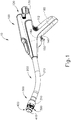
- FIGS. 1-2 depict an exemplary surgical circular stapling instrument (10) that may be used to provide an end-to-end anastomosis between two sections of an anatomical lumen such as a portion of a patient's digestive tract.
- Instrument (10) of this example comprises a handle assembly (100), a shaft assembly (200), a stapling head assembly (300), an anvil (400), and a removable battery pack (120). Each of these components will be described in greater detail below. It should be understood that, in addition to or in lieu of the following, instrument (10) may be further constructed and operable in accordance with at least some of the teachings of U.S. Patent App. No.
- anvil (400) of the present example comprises a head (410) and a shank (420).
- Head (410) includes a proximal surface (412) that defines a plurality of staple forming pockets (414).
- Staple forming pockets (414) are arranged in two concentric annular arrays in the present example.
- Staple forming pockets (414) are configured to deform staples as the staples are driven into staple forming pockets (414) (e.g., deforming a generally "U" shaped staple into a "B" shape as is known in the art).
- Shank (420) defines a bore or lumen (422) and includes a pair of pivoting latch members (430) positioned in bore (422).
- Each latch member (430) includes features that allows anvil (400) to be removably secured to a trocar (330) of stapling head assembly (300) as will be described in greater detail below. It should be understood, however, that anvil (400) may be removably secured to a trocar (330) using any other suitable components, features, or techniques.
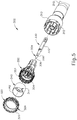
- Stapling head assembly (300) is located at the distal end of shaft assembly (200). As shown in FIGS. 1-2 , anvil (400) is configured to removably couple with shaft assembly (200), adjacent to stapling head assembly (300). As will be described in greater detail below, anvil (400) and stapling head assembly (300) are configured to cooperate to manipulate tissue in three ways, including clamping the tissue, cutting the tissue, and stapling the tissue. As best seen in FIGS. 4-5 , stapling head assembly (300) of the present example comprises a tubular casing (310) housing a slidable staple driver member (350). A cylindraceous inner core member (312) extends distally within tubular casing (310). Tubular casing (310) is fixedly secured to an outer sheath (210) of shaft assembly (200), such that tubular casing (310) serves as a mechanical ground for stapling head assembly (300).
- Trocar (330) is positioned coaxially within inner core member (312) of tubular casing (310). Trocar (330) is operable to translate distally and proximally relative to tubular casing (310) in response to rotation of a knob (130) located at the proximal end of handle assembly (100).
- Trocar (330) comprises a shaft (332) and a head (334). Head (334) includes a pointed tip (336) and an inwardly extending proximal surface (338). Head (334) and the distal portion of shaft (332) are configured for insertion in bore (422) of anvil (420). Proximal surface (338) is configured to complement features of latch members (430) to provide a snap fit between anvil (400) and trocar (330).
- Staple driver member (350) is operable to actuate longitudinally within tubular casing (310) in response to activation of motor (160) as will be described in greater detail below.
- Staple driver member (350) includes two distally presented concentric annular arrays of staple drivers (352).
- Staple drivers (352) are arranged to correspond with the arrangement of staple forming pockets (414) described above.
- each staple driver (352) is configured to drive a corresponding staple into a corresponding staple forming pocket (414) when stapling head assembly (300) is actuated.
- Staple driver member (350) also defines a bore (354) that is configured to coaxially receive core member (312) of tubular casing (310).
- Knife member (340) is coaxially positioned within staple driver member (350).
- Knife member (340) includes a distally presented, sharp circular cutting edge (342).
- Knife member (340) is sized such that knife member (340) defines an outer diameter that is smaller than the diameter defined by the inner annular array of staple drivers (352).
- Knife member (340) also defines an opening that is configured to coaxially receive core member (312) of tubular casing (310).
- a deck member (320) is fixedly secured to tubular casing (310).
- Deck member (320) includes a distally presented deck surface (322) defining two concentric annular arrays of staple openings (324).
- Staple openings (324) are arranged to correspond with the arrangement of staple drivers (352) and staple forming pockets (414) described above.
- each staple opening (324) is configured to provide a path for a corresponding staple driver (352) to drive a corresponding staple through deck member (320) and into a corresponding staple forming pocket (414) when stapling head assembly (300) is actuated.
- the arrangement of staple openings (322) may be modified just like the arrangement of staple forming pockets (414) as described above.
- Deck member (320) defines an inner diameter that is just slightly larger than the outer diameter defined by knife member (340). Deck member (320) is thus configured to allow knife member (340) to translate distally to a point where cutting edge (342) is distal to deck surface (322).
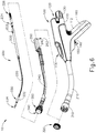
- FIG. 6 shows various components of shaft assembly (200), which extends distally from handle assembly (100) and couples components of stapling head assembly (300) with components of handle assembly (100).
- shaft assembly (200) includes an outer sheath (210) that extends between handle assembly (100) and tubular casing (310).
- outer sheath (210) is rigid and includes a preformed curved section that is configured to facilitate positioning of stapling head assembly (300) within a patient's colon.
- Shaft assembly (200) further includes a trocar actuation rod (220) and a trocar actuation band assembly (230).
- the distal end of trocar actuation band assembly (230) is fixedly secured to the proximal end of trocar shaft (332).
- the proximal end of trocar actuation band assembly (230) is fixedly secured to the distal end of trocar actuation rod (220), such that trocar (330) will translate longitudinally relative to outer sheath (210) in response to translation of trocar actuation band assembly (230) and trocar actuation rod (220) relative to outer sheath (210).
- Trocar actuation band assembly (230) is configured to flex such that trocar actuation band assembly (230) may follow along the preformed curve in shaft assembly (200) as trocar actuation band assembly (230) is translated longitudinally relative to outer sheath (210).
- trocar actuation band assembly (230) has sufficient column strength and tensile strength to transfer distal and proximal forces from trocar actuation rod (220) to trocar shaft (332).
- Trocar actuation rod (220) is rigid.
- a clip (222) is fixedly secured to trocar actuation rod (220) and is configured to cooperate with complementary features within handle assembly (100) to prevent trocar actuation rod (220) from rotating within handle assembly (100) while still permitting trocar actuation rod (220) to translate longitudinally within handle assembly (100).
- Trocar actuation rod (220) further includes a coarse helical threading (224) and a fine helical threading (226).
- Shaft assembly (200) further includes a stapling head assembly driver (240) that is slidably received within outer sheath (210).
- the distal end of stapling head assembly driver (240) is fixedly secured to the proximal end of staple driver member (350).
- the proximal end of stapling head assembly driver (240) is secured to a drive bracket (250) via a pin (242). It should therefore be understood that staple driver member (350) will translate longitudinally relative to outer sheath (210) in response to translation of stapling head assembly driver (240) and drive bracket (250) relative to outer sheath (210).
- Stapling head assembly driver (240) is configured to flex such that stapling head assembly driver (240) may follow along the preformed curve in shaft assembly (200) as stapling head assembly driver (240) is translated longitudinally relative to outer sheath (210). However, stapling head assembly driver (240) has sufficient column strength to transfer distal forces from drive bracket (250) to staple driver member (350).
- handle assembly (100) includes a pistol grip (112) and several components that are operable to actuate anvil (400) and stapling head assembly (300).
- handle assembly (100) includes knob (130), a safety trigger (140) a firing trigger (150), a motor (160), and a motor activation module (180).
- Knob (130) is coupled with trocar actuation rod (220) via a nut (not shown), such that coarse helical threading (224) will selectively engage a thread engagement feature within the interior of the nut; and such that fine helical threading (226) will selectively engage a thread engagement feature within the interior of knob (130).
- These complementary structures are configured such that trocar actuation rod (220) will first translate proximally at a relatively slow rate, then translate proximally at a relatively fast rate, in response to rotation of knob (130).
- knob (130) when anvil (400) is coupled with trocar (330), rotation of knob (130) will provide corresponding translation of anvil relative to stapling head assembly (300). It should also be understood that knob (130) may be rotated in a first angular direction (e.g., clockwise) to retract anvil (400) toward stapling head assembly (300); and in a second angular direction (e.g., counterclockwise) to advance anvil (400) away from stapling head assembly (300). Knob (130) may thus be used to adjust the gap distance between opposing surfaces (412, 322) of anvil (400) and stapling head assembly (300) until a suitable gap distance has been achieved.
- first angular direction e.g., clockwise
- a second angular direction e.g., counterclockwise
- Firing trigger (150) is operable to activate motor (160) to thereby actuate stapling head assembly (300).
- Safety trigger (140) is operable to selectively block actuation of firing trigger (150) based on the longitudinal position of anvil (400) in relation to stapling head assembly (300).
- Handle assembly (100) also includes components that are operable to selectively lock out both triggers (140, 150) based on the position of anvil (400) relative to stapling head assembly (300). When triggers (140, 150) are locked out, firing trigger (150) is prevented from initiating actuation of stapling head assembly (300).
- trigger (150) is only operable to initiate actuation of stapling head assembly (300) when the position of anvil (400) relative to stapling head assembly (300) is within a predefined range.
- firing trigger (150) of the present example includes an integral actuation paddle, such as the paddle shown and described in U.S. Patent App. No. 14/751,231 , entitled “Surgical Stapler with Reversible Motor,” filed June 26, 2015.
- the paddle is configured to actuate a switch of motor activation module (180) ( FIG. 1 ) when firing trigger (150) is pivoted to a fired position.
- Motor activation module (180) is in communication with battery pack (120) and motor (160), such that motor activation module (180) is configured to provide activation of motor (160) with electrical power from battery pack (120) in response to the paddle actuating the switch of motor activation module (180).
- motor (160) will be activated when firing trigger (150) is pivoted. This activation of motor (160) will actuate stapling head assembly (300) as described in greater detail below.
- Battery pack (120) is operable to provide electrical power to a motor (160) as noted above.
- Battery pack (120) may be removably coupled with handle assembly (100) through a snap fit or in any other suitable fashion.
- battery pack (120) and handle assembly (100) may have complementary electrical contacts, pins and sockets, and/or other features that provide paths for electrical communication from battery pack (120) to electrically powered components in handle assembly (100) when battery pack (120) is coupled with handle assembly (100).
- battery pack (120) is unitarily incorporated within handle assembly (100) such that battery back (120) cannot be removed from handle assembly (100).
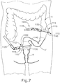
- FIGS. 7-10 show an exemplary surgical procedure for providing a surgical anastomosis using instrument (10).
- an anastomosis may be performed to remove a section of a patient's gastrointestinal (GI) tract.
- GI gastrointestinal
- multiple portions of a patient's colon are severed and stapled to resect a diseased portion (C') of the colon (C).
- C' diseased portion
- the remaining severed and stapled portions of colon (C) are then anastomosed together, as discussed in further detail below.
- endocutter staplers (1000) may be inserted into a patient to sever and staple portions of the patient's colon (C).
- endocutter staplers (1000) may be constructed and operable in accordance with at least some of the teachings of U.S. Pat. No. 4,805,823 , entitled “Pocket Configuration for Internal Organ Staplers,” issued February 21, 1989; U.S. Pat. No. 5,415,334 , entitled “Surgical Stapler and Staple Cartridge,” issued May 16, 1995; U.S. Pat. No. 5,465,895 , entitled “Surgical Stapler Instrument,” issued November 14, 1995; U.S. Pat. No.
- Endocutter staplers (1000) are inserted into the body laparoscopically via respective trocars.
- Endocutter stapler (1000) comprises a shaft (1120) and an end effector (1110) extending from the shaft (1120).
- End effector (1110) comprises a first jaw (1112) and a second jaw (1114).
- First jaw (1112) comprises a staple cartridge (1140).
- Staple cartridge (1140) is insertable into and removable from first jaw (1112), though some variations may provide a staple cartridge that is not removable from (or at least readily replaceable from) first jaw (1112).
- Second jaw (1114) comprises an anvil (1130) that is configured to deform staples ejected from staple cartridge (1140).
- Second jaw (1114) is pivotable relative to first jaw (1112), though some variations pay provide first jaw (1112) as being pivotable relative to the second jaw (1114).
- Endocutter staplers (1000) may be configured ad operable in accordance with at least some of the teachings of U.S. Pub. No. 2013/0168435 , entitled “Surgical Stapling Instrument with an Articulatable End Effector,” published July 4, 2013. While end effector (1110) is straight and is thus configured to apply a straight line of staples (185) in the present example, in other examples end effector (1110) may be curved and may thus apply a curved line of staples (185).
- Anvil (1130) of endocutter stapler (1000) can be opened such that anvil (1130) and staple cartridge (1140) of endocutter stapler (1000) are positioned relative to the patient's colon (C).
- anvil (1130) is moved into a closed position, anvil (1130) clamps the colon (C) against staple cartridge (1140).
- endocutter stapler (1000) can be operated to sever and staple the colon (C) at a first, or upper, location.
- three linear rows of staples (185) are implanted on the upper side of the severed upper portion (UC) of colon (C) and three rows of the staples (185) are implanted in the adjacent region of the diseased portion (C') of the colon (C).
- the same endocutter stapler (1000) if reloaded with another cartridge (1140)), or another endocutter stapler (1000), can be operated to sever and staple the colon (C) at a second, or lower, location.
- three linear rows of staples (285) implanted on the lower side of the severed lower portion (LC) of the colon (C) and three rows of staples (285) are implanted in the adjacent region of the diseased portion (C') of the colon (C).
- other suitable configurations of staples may be implanted onto the upper portion (UC) and/or the lower portion (LC) of the colon (C).
- circular stapler (10) may be utilized to anastomose the upper portion (UC) and the lower portion (LC) of the colon (C).
- An operator inserts a portion of shaft (210) and stapling head assembly (300) into the rectum (R) of the patient into the lower portion (LC) of the colon (C).
- a user then inserts trocar (330) through the rows of staples (285).
- Trocar (330) of circular stapler (10) may then be positioned in the upper portion of the colon C.
- the sidewall of the upper portion of the colon C can be incised and trocar (330) can then be positioned inside the upper portion.
- Anvil (400) may then be directed into the upper portion of the colon (C) and connected to trocar (330) in the manner discussed above and as shown in FIG. 8 .
- knob (130) may be rotated in a first angular direction (e.g., clockwise) to retract anvil (400) toward stapling head assembly (300); and in a second angular direction (e.g., counterclockwise) to advance anvil (400) away from stapling head assembly (300).
- Knob (130) may thus be used to adjust the gap distance between opposing surfaces of anvil (400) and stapling head assembly (300) until a suitable gap distance has been achieved, such as in the manner discussed in U.S. Patent App. No. 14/751,506 .
- flap regions (FR) are formed in the lower portion (LC) of the colon (C) as anvil (400) is drawn toward stapling head assembly (300). These flap regions (FR) extend outwardly from the region of tissue compressed between anvil (400) and stapling head assembly (300).
- stapling head assembly (300) is configured to apply annular arrays of staples (385) in the tissue captured between anvil (400) and stapling head assembly (300).
- Knife member (340) is advanced toward anvil (440) to sever the tissue positioned radially inwardly with respect to the annular arrays of staples (385) applied by circular stapling instrument (10).
- anvil (400) and stapling head assembly (300) may together be withdrawn from the patient's rectum (R).
- the incision that was used to insert anvil (400) into the upper portion (UC) of the colon (C) may be closed via suturing or using any other suitable technique.
- the upper portion (UC) of the colon (C) and the lower portion (LC) of the colon (C) are held together by the annular array of staples (385) deployed by circular stapling instrument (10).
- the deployed annular array of staples (385) forms an anastomosis (A) that allows fluid tight communication from the upper portion (UC) of the colon (C) to the lower portion (LC) of the colon (C).
- Some of staples (285) that were deployed by endocutter stapler (1000) will be removed with the tissue that was transected by knife member (340) during actuation of stapling head assembly (300).
- staples (385) that were deployed by circular stapling instrument (10) may overlap with at least some of staples (285) that were deployed by endocutter stapler (1000) in the procedure described above with reference to FIGS. 7-10 . Such overlap may prevent proper formation of staples (385), which may compromise the integrity of anastomosis (A) in the long term.
- at least some of staples (285) that were deployed by endocutter stapler (1000) may interfere with compression of tissue between anvil (400) and deck member (320) and/or the traversal of knife member (340) through the tissue, which may also compromise the integrity of anastomosis (A) in the long term.
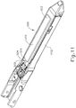
- FIG. 11 shows an exemplary alternative staple cartridge (500) inserted in first jaw (1112) of end effector (1110).
- Staple cartridge (500) is substantially similar to staple cartridge (1140), except that staple cartridge (500) includes two rows of staple cavities (not shown) on each side of slot (502) of instead of three rows. Therefore, when staple cartridge (500) is incorporated into end effector (1110), two rows of staples (520) are implanted onto opposing, severed portions of tissue rather than three rows of staples (520).
- staple cartridge (500) includes a buttress (510) that is removably secured to deck (504) of staple cartridge (500).
- buttress (510) may be secured to deck (504) in accordance with any of the teachings of U.S. Patent App.
- Buttress (510) of the present example has a first end (512) and a second end (514).
- Buttress (510) is formed of an elastic material that is resiliently biased to assume a longitudinally contracted configuration. In FIG. 11 , buttress (510) is elongated from its natural position while fixed to deck (504). It should therefore be understood that buttress (510) is resiliently biased to longitudinally contract from the configuration shown in FIG. 11 , to draw ends (401, 402) toward each other. It should also be understood that the means used for connecting buttress (510) to deck (504) imparts a force on buttress (510) to prevent buttress (510) from contracting to its natural length.
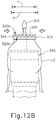
- staple cartridge (500) may be implemented in endocutter stapler (1000). Therefore, endocutter stapler (1000) may drive a plurality of staples through deck (504) and buttress (510) onto the severed lower portion (LC) of the colon (C) as shown in FIGS. 12A-12B .
- endocutter stapler (1000) may drive a plurality of staples through deck (504) and buttress (510) onto the severed lower portion (LC) of the colon (C) as shown in FIGS. 12A-12B .
- buttress (510) will be captured between the crowns of the driven staples (520) and the adjacent tissue.
- FIGS. 12A-12B show buttress (510) detached from deck (504) and secured to tissue by a first row of staples (520a) and a second row of staples (520b).
- first row of staples (520a) and second row of staples (520b) are formed, however any suitable number of staple rows may be used, such as three or four rows of staples.
- endocutter stapler (1000) has simultaneously transected and sealed the lower portion (LC) of colon (C) with a blade and staples (520), respectively, in accordance with conventional endocutter stapler operation.
- FIG. 12A shows buttress (510) secured to the lower portion (LC) of the colon (C) by staples (520), immediately after buttress (510) is detached from deck (504), before buttress (510) has had time to contract to its natural position.
- the flap regions (FR) define a width (a) that is substantially greater than the diameter (b) of knife member (340), as described above.
- FIG. 12B shows buttress (510) in the contracted configuration.
- buttress (510) is detached from deck (504), there is no longer a force elongating buttress (510), such that first end (512) and second end (514) are allowed to contract toward each other.
- First end (512) and second end (514) of buttress (510) may contract toward each other in a linear fashion (e.g., such that the contracted form of buttress (510) is still linear), a coiling fashion (e.g., such that the contracted form of buttress (510) forms a coil), in an arching fashion (e.g., such that the contracted form of buttress (510) forms an arch), in a wave-like fashion (e.g., such that the contracted form of buttress (510) forms a wave-like configuration), or in any other suitable manner as will be apparent to a person having ordinary skill in the art in view of the teachings herein.
- buttress (510) may contract at any multitude of suitable rates.
- first staple line (520a) and second staple line (520b) are attached to buttress (510), the distance from each staple in first and second staple line (520a, 520b) decreases as well.
- the contraction of buttress (510) has transversely contracted the severed end of the lower portion (LC) of the colon (C), such that the severed end of the lower portion (LC) of the colon (C) defines a contracted width (c).
- This contracted width (c) is smaller than the diameter (b) of knife member (340).
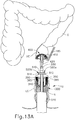
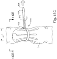
- FIGS. 13A-13C show steps of an anastomosis procedure similar to the procedure shown in FIGS. 7-10 .
- Upper colon portion (UC) and lower colon portion (LC) are shown to have been severed and stapled in a similar manner to that shown in FIGS. 7-8 .
- at least the lower colon portion (LC) has been severed and stapled utilizing staple cartridge (500).
- Lower colon portion (LC) therefore includes staples (520) and buttress (510) coupled thereto in the manner discussed above.
- a portion of shaft (210) and stapling head assembly (300) are inserted into the rectum (R) of the patient and into the lower portion (LC) of the colon (C).
- trocar (330) is passed through the lines of staples (520) such that trocar (330) is exposed out of lower colon portion (LC).
- Anvil (400) is shown to be positioned in the upper portion (UC) of the colon (C), with shank (420) extending through an opening of the upper colon portion (UC).
- buttress (510) is in the contracted state shown in FIG. 12B , resulting in the lines of staples (520) and the severed portion of the lower colon portion (LC) being drawn inwardly toward trocar (330).
- the tissue has the effective width (c) that is smaller than the diameter (b) of knife member (340), such that staples (520), buttress (510), and flap regions (FR) are all positioned within the cylindrical plane defined by knife member (340).
- the operator then connects shank (420) to trocar (330) in the manner discussed above.
- the operator may then draw anvil (400) toward stapling head assembly (300), in the manner described above (e.g., utilizing knob (130)), thus also drawing the upper colon portion (UC) toward the lower colon portion (LC).
- the operator may then retract trocar (330) until the tissue of the upper colon portion (UC) and the lower colon portion (LC) are compressed against the deck member (320) to achieve a desirable gap distance, as shown in FIG. 13B and discussed above.
- the operator may then actuate trigger (150) to actuate stapling head assembly (300), resulting in the stapling and severing of tissue in a similar manner as shown in FIG. 9 .
- trigger (150) to actuate stapling head assembly (300), resulting in the stapling and severing of tissue in a similar manner as shown in FIG. 9 .
- the staples (520), buttress (510), and flap regions (FR) all being positioned within the cylindrical plane defined by knife member (340), the combination of staples (585), buttress (510), and flap regions (FR) are all severed from the adjacent tissue.
- no staples (520) or components of buttress (510) are disposed in the tissue that remains at the resulting anastomosis (A) site as shown in FIG. 13C .
- staples (520) do not impede the successful operation of circular stapler (10), and there are no flap regions (FR) extending outwardly from the anastomosis (A) site.
- the severed portion of tissue including staples (520) and buttress (510) may be removed by the operator via the patient's rectum.
- FIGS. 14-16B show another feature that may be used to prevent the outward extension of flap regions (FR) and position all of the tissue at the severed end of lower colon portion (LC) within the diameter (b) of knife member (340).
- FIGS. 14-16B show a bendable pleating member (600) that may be used to contract a bodily lumen such as the colon (C) inwardly, while forming an angularly spaced array of pleats in the bodily lumen.
- bendable pleating member (600) includes a pulling end (604), a first bendable body (610) unitarily connected to a second bendable body (614), and a receiving end (602).
- Pulling end (604) includes a tapered portion (608).
- Receiving end (602) includes a slot (606) that is configured to receive pulling end (604).
- Tapered portion (608) is narrower compared to the remaining portion of pulling end (604) in order to better allow an operator to guide pulling end (604) within the confines of slot (606).
- first and second bendable bodies (610, 614) bend form a circumferential path.
- bendable pleating member (600) is dimensioned to encompass a bodily lumen, such as colon (C), when forming the circumferential path. The farther pulling end (604) travels through slot (606) of receiving end (602), the smaller the circumferential path becomes.
- First bendable body (610) includes an entry channel (611) that is configured to initially receive a wire (660), while second bendable body includes a plurality of individual protrusions (612) that are also configured to receive wire (660).
- the structure of wire (660) will be described in greater detail below.
- the current example of bendable pleating member (600) shows four individual protrusions (612). However, any suitable number of individual protrusions (612) may be utilized as will be apparent to one having ordinary skill in the art in view of the teachings herein.
- Each individual protrusion (612) includes an angled entry face (622), an angled exit face (620), a contact face (624) defined by angled entry face (622) and angled exit face (620), a wire guide channel (618) extending from angled entry face (622) through angled exit face (620), and a wire exit (626) extending from wire guide channel (618) to contact face (624).
- Receiving end (602) also includes wire guide channel (618) and wire exit (616) for initial introduction of wire (660) to individual protrusions (612).
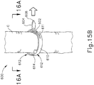
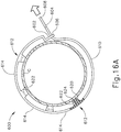
- FIGS. 15A-16B show pleating member (600) being wrapped about colon (C). As shown, pleating member (600) is dimensioned to encompass colon (C). It should be understood that the process shown in FIGS. 15A-16B may be performed before endocutter staplers (1000) are used to transect the colon (C) as described above with reference to FIG. 7 .
- Pleating member (600) is initially placed adjacent to the colon (C) as shown in FIG. 15A , and then pulling end (604) is passed through slot (606) of receiving end (602) to wrap pleating member (600) about the colon (C) as shown in FIGS. 15B and 16A . As pulling end (604) is further pulled through slot (606) of receiving end (602), the circumference defined by pleating member (600) decreases as shown in FIGS. 15C and 16B .
- pleating member (600) bears inwardly on the colon (C) and thereby reduces the diameter of the colon (C) at the region being engaged by pleating member (600).
- contact faces (624) of protrusions (612) provide focused pressure on adjacent regions about the circumference of the colon (C).
- the tissue of the colon (C) may eventually engage angled faces (620, 622) of protrusions (612).
- the trapezoidal configuration of protrusions (612) ultimately causes pleats (650) to form in a bunched-up region of the colon (C), as also shown in FIGS. 15C and 16B .
- the reduced diameter (d) of the bunched-up region of the colon (C) is smaller than the diameter (b) of knife member (340).
- the bunched-up tissue containing pleats (650) will fit within the cylindrical plane defined by knife member (340).
- wire (660) is introduced into entry channel (611).
- Wire (660) of the present example has a sharp distal tip (662) (e.g., similar to a needle) and a flexible body.
- the body of wire (660) has sufficient column strength to enable wire (660) to be pushed through the tissue of the colon (C); yet wire (660) also has enough flexibility to enable wire (660) to traverse an arcuate path as described below.
- Entry channel (611) is located along pulling end (604) and first bendable body (610) in such a way as to align with wire guide channel (618) of receiving end (602) when pleating member (600) is in the constricting configuration. Additionally, each wire guide channel (618) aligns to define an arcuate path for wire (660). Wire guide channel (618) is also located on each angled entry face (622) and angled exit face (620) so that wire (660) penetrates colon (C) while traveling along the arcuate path. In other words, wire (660) is capable of traveling from entry channel (611), through the arcuate path defined by each wire guide channel (618).
- wire is disposed in the tissue of the colon (C) in a manner similar to a purse-string suture. This arrangement is shown in FIG. 16B , with wire (660) passed through the pleats (650) formed in the tissue of the colon (C).
- wire (660) Once wire (660) has traveled along the complete arcuate path defined by the combination of wire guide channels (618), pulling end (604) may be retracted out of slot (606), allowing bendable pleating member (600) may be removed from colon (C).
- wire (660) will not be disturbed by the removal of bendable pleating member (600) because wire exits (616) provide a path for wire (660) to disconnect from bendable pleating member (600) while wire (660) remains disposed in the tissue of the colon (C). With bendable pleating member (600) removed, wire (660) remains in place to hold the tissue of the colon (C) in the bunched-up configuration, maintaining the presence of pleats (650).
- pleating member (600) is used to bunch-up, pleat, and guide wire (660) into a lower portion (LC) of the colon (C) that is between a diseased portion (C') of the colon (C) and the patient's rectum (R).
- the operator may then use an endocutter stapler (1000) to separate an upper region of the diseased portion (C') of the colon (C) from an upper portion (UC) of the colon (C) as described above with reference to FIG. 7 .
- an endocutter stapler (1000) instead of using an endocutter stapler (1000) to separate a lower region of the diseased portion (C') of the colon (C) from the lower portion (LC) of the colon (C) as described above with reference to FIG.
- the operator may simply use a conventional cutting instrument (e.g., shears, knife, etc.) to cut the diseased portion (C') of the colon (C) from the lower portion (LC) of the colon (C), just above the bunched-up region of the colon (C).
- a conventional cutting instrument e.g., shears, knife, etc.
- Trocar (330) may be advanced to a position where trocar (330) passes through the bunched-up region of the colon (C) and protrudes from the severed end of the lower portion (LC) of the colon (C).
- the operator may then secure anvil (400) to trocar (330) and clamp the adjacent regions of tissue as described above with reference to FIG. 9 .
- the reduced diameter (d) of the bunched-up region of the colon (C) is smaller than the diameter (b) of knife member (340), such that the bunched-up tissue containing pleats (650) and wire (660) will fit within the cylindrical plane defined by knife member (340) at this stage.
- the process will result in an anastomosis that is substantially identical to the anastomosis (A) shown in FIG. 13C , without any outwardly protruding flap regions (FR).
- receiving end (602) includes a pawl feature and pulling end (604) includes a set of integral teeth.
- the pawl of receiving end (602) ratchets along the integral teeth of pulling end (604) as pleating member (600) is cinched around the colon (C).
- the pawl and teeth thus cooperate to hold pleating member (600) in a cinched configuration, thereby holding the lower colon portion (LC) in the bunched-up, pleated (650) configuration.
- the cinched pleating member (600) may still be within the cylindrical plane defined by knife member (340), such that pleating member (600) is severed away with the adjacent tissue when stapling head assembly (330) is actuated to create the anastomosis (A).
- a suture and needle may be used in place of wire (660). Still other variations will be apparent to those of ordinary skill in the art in view of the teachings herein.
- FIGS. 17-18 show another exemplary pleating member (700) that may be used to form pleats (750) in a colon (C).
- pleating member (700) of this example is positioned inside a bodily lumen such as the colon (C) in order to form pleats (750) in the bodily lumen.
- pleating member (700) of this example is configured to guide a needle (760) and suture (765) along an arcuate path.
- pleating member (600), needle (760), and suture (765) are operable to form and maintain pleats (750) in a bunched-up region of the colon (C) prior to transection of the colon (C).
- intraluminal pleating member (700) includes a body (730) having an annular inner surface (740) and an annular outer surface (714), and a plurality of protrusions (712) extending radially outwardly from annular outer surface (714). Protrusions (712) are equidistantly spaced angularly about the circumference of body (730).
- Annular inner surface (740) defines a central bore (742) while a plurality of radial bores (746) extend outwardly from annular inner surface (740) to annular outer surface (714).
- radial bores (746) allow for intraluminal pleating member (700) to form pleats in the colon (C).
- any suitable number of radial bores (746) may be used as will be apparent to a person having ordinary skill in the art in view of the teachings herein.
- Each radially extending protrusion (712) includes a pair of side faces (720), an outer face (724) connecting each pair of side faces (720), a guide channel (708) extending to each side face (720) in the pair of side faces (720), and suture exit channel (716) extending from guide channel (708) to outer face (724).
- Each guide channel (708) circumferentially aligns with the other wire guide channels (708) in the plurality of radially extending protrusions (712) to define an arcuate path for a needle (760) and a suture (765). While in the current example, suture exit channel (716) is shown extending from guide channel (708) to outer face (724), suture exit channel (716) may also extend from guide channel (708) to a side face (720).
- intraluminal pleating member (700) may be placed in the lower portion (LC) of colon (C) transanally and positioned adjacent to the location of a first desired transection (e.g., between a diseased portion (C') of the colon (C) and the patient's rectum (R)).
- a vacuum source (not shown) is driven to communicate with central bore (742), and the region of colon (C) above the location of pleating member (700) is temporarily crimped (e.g., using graspers, a clip, etc.).
- the vacuum is communicated through radial bores (746) and thereby draws the tissue of colon (C) inwardly toward annular outer surface (714).
- Protrusions (712) are rigid and thus bear outwardly on the tissue of colon (C), such that protrusions (712) cooperate with the suction provided through radial bores (746) to form pleats (750) in the colon (C).
- the resulting bunched-up region of the colon (C) has a diameter that is smaller than the diameter (b) of knife member (340).
- the bunched-up tissue containing pleats (750) will fit within the cylindrical plane defined by knife member (340).
- a vacuum is used to draw the tissue of the colon (C) inwardly toward pleating member (700) in this example
- any other suitable devices or techniques may be used to draw the tissue of the colon (C) inwardly toward pleating member (700).
- a device having a complementary shape with respect to intraluminal pleating member (700) could be placed on the outside of colon (C) to press tissue into intraluminal pleating member (700).
- the complementary shaped device could be resiliently biased to engage intraluminal pleating member (700) and have similar wire guide channels and suture exits.
- Other variations will be apparent to those of ordinary skill in the art in view of the teachings herein.
- needle (760) and suture (765) may be administered from the outside of colon (C) through guide channels (708) along the arcuate path. Once needle (760) and suture (765) have traversed each guide channel (708) or each radially extending protrusion (712), the vacuum source or other device forcing colon (C) to take the shape of intraluminal pleating member (700) may be removed. Intraluminal pleating member (700) may then be removed from colon (C) transanally, with suture (765) remaining within colon (C) due to the presence of suture exits (716).
- suture (765) decouples from intraluminal pleating member (700) via suture exits (716). With pleating member (700) removed, suture (765) remains in place to hold the tissue of the colon (C) in the bunched-up configuration, maintaining the presence of pleats (750).
- pleating member (700) is used to bunch-up, pleat, and guide needle (760) and suture (765) in a lower portion (LC) of the colon (C) that is between a diseased portion (C') of the colon (C) and the patient's rectum (R).
- the operator may then use an endocutter stapler (1000) to separate an upper region of the diseased portion (C') of the colon (C) from an upper portion (UC) of the colon (C) as described above with reference to FIG. 7 .
- the operator may simply use a conventional cutting instrument (e.g., shears, knife, etc.) to cut the diseased portion (C') of the colon (C) from the lower portion (LC) of the colon (C), just above the bunched-up region of the colon (C).
- a conventional cutting instrument e.g., shears, knife, etc.
- Trocar (330) may be advanced to a position where trocar (330) passes through the bunched-up region of the colon (C) and protrudes from the severed end of the lower portion (LC) of the colon (C).
- the operator may then secure anvil (400) to trocar (330) and clamp the adjacent regions of tissue as described above with reference to FIG. 9 .
- the reduced diameter (d) of the bunched-up region of the colon (C) is smaller than the diameter (b) of knife member (340), such that the bunched-up tissue containing pleats (750) and suture (765) will fit within the cylindrical plane defined by knife member (340) at this stage.
- the process will result in an anastomosis that is substantially identical to the anastomosis (A) shown in FIG. 13C , without any outwardly protruding flap regions (FR).
- Versions of the devices described above may have application in conventional medical treatments and procedures conducted by a medical professional, as well as application in robotic-assisted medical treatments and procedures.
- various teachings herein may be readily incorporated into a robotic surgical system such as the DAVINCITM system by Intuitive Surgical, Inc., of Sunnyvale, California.
- Versions described above may be designed to be disposed of after a single use, or they can be designed to be used multiple times. Versions may, in either or both cases, be reconditioned for reuse after at least one use. Reconditioning may include any combination of the steps of disassembly of the device, followed by cleaning or replacement of particular pieces, and subsequent reassembly. In particular, some versions of the device may be disassembled, and any number of the particular pieces or parts of the device may be selectively replaced or removed in any combination. Upon cleaning and/or replacement of particular parts, some versions of the device may be reassembled for subsequent use either at a reconditioning facility, or by a user immediately prior to a procedure.
- reconditioning of a device may utilize a variety of techniques for disassembly, cleaning/replacement, and reassembly. Use of such techniques, and the resulting reconditioned device, are all within the scope of the present application.
- versions described herein may be sterilized before and/or after a procedure.
- the device is placed in a closed and sealed container, such as a plastic or TYVEK bag.
- the container and device may then be placed in a field of radiation that can penetrate the container, such as gamma radiation, x-rays, or high-energy electrons.
- the radiation may kill bacteria on the device and in the container.
- the sterilized device may then be stored in the sterile container for later use.
- a device may also be sterilized using any other technique known in the art, including but not limited to beta or gamma radiation, ethylene oxide, or steam.
Landscapes
- Health & Medical Sciences (AREA)
- Life Sciences & Earth Sciences (AREA)
- Surgery (AREA)
- Molecular Biology (AREA)
- Engineering & Computer Science (AREA)
- Biomedical Technology (AREA)
- Heart & Thoracic Surgery (AREA)
- Medical Informatics (AREA)
- Nuclear Medicine, Radiotherapy & Molecular Imaging (AREA)
- Animal Behavior & Ethology (AREA)
- General Health & Medical Sciences (AREA)
- Public Health (AREA)
- Veterinary Medicine (AREA)
- Reproductive Health (AREA)
- Vascular Medicine (AREA)
- Surgical Instruments (AREA)
Claims (12)
- Vorrichtung, umfassend eine Klammerkassette (500), wobei die Klammerkassette umfasst:(i) eine Vielzahl von Klammern (520),(ii) ein Deck (504), wobei das Deck eine Vielzahl von Öffnungen definiert, wobei jede Öffnung der Vielzahl von Öffnungen mit einer entsprechenden Klammer der Vielzahl von Klammern assoziiert ist, so dass jede Klammer dazu ausgelegt ist, eine entsprechende Öffnung der Vielzahl von Öffnungen zu durchqueren, und(iii) eine Versteifung (510), die am Klammerdeck befestigt ist, wobei die Versteifung dazu ausgelegt ist, sich als Reaktion darauf, dass die Klammern durch die entsprechenden Öffnungen des Decks getrieben werden, vom Klammerdeck zu lösen, dadurch gekennzeichnet, dass die Versteifung elastisch vorgespannt ist, um von einer ersten Konfiguration, während sie am Deck befestigt ist, in eine zweite Konfiguration, wenn sie vom Deck gelöst ist, überzugehen, wobei die Versteifung eine erste Länge in der ersten Konfiguration aufweist, wobei die Versteifung eine zweite Länge in der zweiten Konfiguration aufweist, wobei die erste Länge länger als die zweite Länge ist.
- Vorrichtung nach Anspruch 1, wobei die Versteifung in der ersten Konfiguration im Wesentlichen linear ist.
- Vorrichtung nach Anspruch 2, wobei die Versteifung in der zweiten Konfiguration im Wesentlichen linear ist.
- Vorrichtung nach einem der vorhergehenden Ansprüche, wobei die Versteifung elastisch vorgespannt ist, um sich in die zweite Länge zusammenzuziehen.
- Vorrichtung nach Anspruch 4, wobei sich die Versteifung längs entlang einer Längsachse erstreckt, wobei die Versteifung elastisch vorgespannt ist, um sich entlang der Längsachse in die zweite Länge zusammenzuziehen.
- Vorrichtung nach Anspruch 4 oder 5, wobei die Versteifung ein elastisches Material umfasst.
- Vorrichtung nach einem der vorhergehenden Ansprüche, wobei die Vielzahl von Klammern dazu ausgelegt ist, sich als Reaktion darauf, dass die Klammern durch die entsprechenden Öffnungen des Decks getrieben werden, an der Versteifung zu befestigen.
- Vorrichtung nach Anspruch 7, wobei die Vielzahl von Klammern dazu ausgelegt ist, sich als Reaktion auf den Übergang der Versteifung von der ersten Konfiguration in die zweite Konfiguration zueinander zu bewegen.
- Vorrichtung nach einem der vorhergehenden Ansprüche, ferner umfassend ein zirkuläres Klammergerät, wobei das zirkuläre Klammergerät umfasst:(i) einen Amboss, und(ii) eine Klammerkopfanordnung, wobei die Klammerkopfanordnung umfasst:(A) eine Stange, die für einen Eingriff in den Amboss ausgelegt ist, wobei die Stange dazu ausgelegt ist, Gewebe zu durchqueren, wobei die Klammern und die Versteifung am Gewebe befestigt sind,(B) ein Messerelement, das zur Bildung einer kreisförmigen Schnittlinie in Gewebe ausgelegt ist, und(C) einen Klammertreiber, wobei der Amboss und die Klammerkopfanordnung dazu ausgelegt sind, zum Einklemmen und Klammern von Gewebe zusammenzuwirken.
- Vorrichtung nach Anspruch 9, wobei das Messerelement einen Durchmesser definiert, wobei die zweite Länge kleiner als der Durchmesser des Messerelements ist, und wobei die erste Länge größer als der Durchmesser des Messerelements sein kann.
- Vorrichtung nach einem der vorhergehenden Ansprüche, wobei die Versteifung mit einem Klebematerial am Deck befestigt ist.
- Vorrichtung nach einem der vorhergehenden Ansprüche, wobei das Deck ferner einen sich längs erstreckenden Kanal definiert, wobei die Öffnungen ein erstes Paar von sich parallel längs erstreckenden Reihen von Öffnungen und ein zweites Paar von sich parallel längs erstreckenden Reihen von Öffnungen umfassen, wobei das erste Paar auf einer Seite des Kanals angeordnet ist und das zweite Paar auf der anderen Seite des Kanals angeordnet ist, wobei sich die Versteifung über das erste und das zweite Paar von sich längs erstreckenden Reihen von Öffnungen erstreckt.
Applications Claiming Priority (1)
| Application Number | Priority Date | Filing Date | Title |
|---|---|---|---|
| US14/863,928 US10499909B2 (en) | 2015-09-24 | 2015-09-24 | Apparatus and method for pleating a bodily lumen |
Publications (3)
| Publication Number | Publication Date |
|---|---|
| EP3146917A2 EP3146917A2 (de) | 2017-03-29 |
| EP3146917A3 EP3146917A3 (de) | 2017-04-05 |
| EP3146917B1 true EP3146917B1 (de) | 2021-09-22 |
Family
ID=56990328
Family Applications (1)
| Application Number | Title | Priority Date | Filing Date |
|---|---|---|---|
| EP16190323.2A Active EP3146917B1 (de) | 2015-09-24 | 2016-09-23 | Vorrichtung zur faltung eines körperlumens |
Country Status (6)
| Country | Link |
|---|---|
| US (1) | US10499909B2 (de) |
| EP (1) | EP3146917B1 (de) |
| JP (1) | JP6838055B2 (de) |
| CN (1) | CN108289685B (de) |
| BR (1) | BR112018005895A2 (de) |
| WO (1) | WO2017053187A1 (de) |
Families Citing this family (19)
| Publication number | Priority date | Publication date | Assignee | Title |
|---|---|---|---|---|
| US10709452B2 (en) | 2013-09-23 | 2020-07-14 | Ethicon Llc | Methods and systems for performing circular stapling |
| US10980542B2 (en) | 2016-11-14 | 2021-04-20 | Ethicon Llc | Circular surgical stapler with recessed deck |
| US10492790B2 (en) * | 2015-09-24 | 2019-12-03 | Ethicon Llc | Apparatus and method for cinching a straight staple line |
| US10966717B2 (en) * | 2016-01-07 | 2021-04-06 | Covidien Lp | Surgical fastener apparatus |
| USD837373S1 (en) * | 2016-11-14 | 2019-01-01 | Ethicon Llc | Surgical stapler |
| US10603041B2 (en) * | 2016-11-14 | 2020-03-31 | Ethicon Llc | Circular surgical stapler with angularly asymmetric deck features |
| USD830550S1 (en) * | 2016-11-14 | 2018-10-09 | Ethicon Llc | Surgical stapler |
| USD833608S1 (en) | 2016-11-14 | 2018-11-13 | Ethicon Llc | Stapling head feature for surgical stapler |
| USD833010S1 (en) * | 2017-02-17 | 2018-11-06 | Ethicon Llc | Stapling head feature for a surgical stapler |
| EP3577475A1 (de) | 2017-03-02 | 2019-12-11 | Rosemount Inc. | Trendfunktionen für teilentladung |
| US10163309B1 (en) * | 2017-06-27 | 2018-12-25 | Ethicon Llc | Surgical instrument with integrated and independently powered displays |
| US11337704B2 (en) | 2017-08-24 | 2022-05-24 | Jichi Medical University | Tool for treating excised end of body organ |
| US11067639B2 (en) | 2017-11-03 | 2021-07-20 | Rosemount Inc. | Trending functions for predicting the health of electric power assets |
| US10794736B2 (en) | 2018-03-15 | 2020-10-06 | Rosemount Inc. | Elimination of floating potential when mounting wireless sensors to insulated conductors |
| US11181570B2 (en) | 2018-06-15 | 2021-11-23 | Rosemount Inc. | Partial discharge synthesizer |
| US10833531B2 (en) | 2018-10-02 | 2020-11-10 | Rosemount Inc. | Electric power generation or distribution asset monitoring |
| US10923876B1 (en) * | 2019-08-09 | 2021-02-16 | Lockheed Martin Corporation | Phase-change material (PCM) embedded heat exchanger assembly for laser diode cooling and systems and methods thereof |
| US11313895B2 (en) | 2019-09-24 | 2022-04-26 | Rosemount Inc. | Antenna connectivity with shielded twisted pair cable |
| US11642131B2 (en) * | 2021-05-17 | 2023-05-09 | Covidien Lp | Devices and methods for shortening a rectal stump during a lower anterior resection procedure |
Family Cites Families (69)
| Publication number | Priority date | Publication date | Assignee | Title |
|---|---|---|---|---|
| US4805823A (en) | 1988-03-18 | 1989-02-21 | Ethicon, Inc. | Pocket configuration for internal organ staplers |
| US4950285A (en) * | 1989-11-27 | 1990-08-21 | Wilk Peter J | Suture device |
| GR920100358A (el) | 1991-08-23 | 1993-06-07 | Ethicon Inc | Οργανο συρραφής χειρουργικής αναστομώσεως. |
| US5333773A (en) | 1991-08-23 | 1994-08-02 | Ethicon, Inc. | Sealing means for endoscopic surgical anastomosis stapling instrument |
| US5350104A (en) | 1991-08-23 | 1994-09-27 | Ethicon, Inc. | Sealing means for endoscopic surgical anastomosis stapling instrument |
| US5397324A (en) * | 1993-03-10 | 1995-03-14 | Carroll; Brendan J. | Surgical stapler instrument and method for vascular hemostasis |
| US5415334A (en) | 1993-05-05 | 1995-05-16 | Ethicon Endo-Surgery | Surgical stapler and staple cartridge |
| US5542594A (en) * | 1993-10-06 | 1996-08-06 | United States Surgical Corporation | Surgical stapling apparatus with biocompatible surgical fabric |
| US5465895A (en) | 1994-02-03 | 1995-11-14 | Ethicon Endo-Surgery, Inc. | Surgical stapler instrument |
| US5597107A (en) | 1994-02-03 | 1997-01-28 | Ethicon Endo-Surgery, Inc. | Surgical stapler instrument |
| US5814057A (en) * | 1994-06-03 | 1998-09-29 | Gunze Limited | Supporting element for staple region |
| US5632432A (en) | 1994-12-19 | 1997-05-27 | Ethicon Endo-Surgery, Inc. | Surgical instrument |
| US5704534A (en) | 1994-12-19 | 1998-01-06 | Ethicon Endo-Surgery, Inc. | Articulation assembly for surgical instruments |
| WO1997001989A1 (en) * | 1995-07-03 | 1997-01-23 | Frater Dirk A | System for mounting bolster material on tissue staplers |
| US5702409A (en) * | 1995-07-21 | 1997-12-30 | W. L. Gore & Associates, Inc. | Device and method for reinforcing surgical staples |
| US5810855A (en) * | 1995-07-21 | 1998-09-22 | Gore Enterprise Holdings, Inc. | Endoscopic device and method for reinforcing surgical staples |
| US5814055A (en) | 1995-09-19 | 1998-09-29 | Ethicon Endo-Surgery, Inc. | Surgical clamping mechanism |
| US5752965A (en) * | 1996-10-21 | 1998-05-19 | Bio-Vascular, Inc. | Apparatus and method for producing a reinforced surgical fastener suture line |
| US5769892A (en) * | 1996-10-22 | 1998-06-23 | Mitroflow International Inc. | Surgical stapler sleeve for reinforcing staple lines |
| US6099551A (en) * | 1998-03-12 | 2000-08-08 | Shelhigh, Inc. | Pericardial strip and stapler assembly for dividing and sealing visceral tissues and method of use thereof |
| US6325810B1 (en) * | 1999-06-30 | 2001-12-04 | Ethicon, Inc. | Foam buttress for stapling apparatus |
| US6638285B2 (en) * | 2001-04-16 | 2003-10-28 | Shlomo Gabbay | Biological tissue strip and system and method to seal tissue |
| US6656193B2 (en) * | 2001-05-07 | 2003-12-02 | Ethicon Endo-Surgery, Inc. | Device for attachment of buttress material to a surgical fastening device |
| US7380696B2 (en) | 2003-05-20 | 2008-06-03 | Ethicon Endo-Surgery, Inc. | Articulating surgical stapling instrument incorporating a two-piece E-beam firing mechanism |
| US7143923B2 (en) | 2003-05-20 | 2006-12-05 | Ethicon Endo-Surgery, Inc. | Surgical stapling instrument having a firing lockout for an unclosed anvil |
| US7380695B2 (en) | 2003-05-20 | 2008-06-03 | Ethicon Endo-Surgery, Inc. | Surgical stapling instrument having a single lockout mechanism for prevention of firing |
| US7000818B2 (en) | 2003-05-20 | 2006-02-21 | Ethicon, Endo-Surger, Inc. | Surgical stapling instrument having separate distinct closing and firing systems |
| US7547312B2 (en) * | 2003-09-17 | 2009-06-16 | Gore Enterprise Holdings, Inc. | Circular stapler buttress |
| US7434715B2 (en) | 2003-09-29 | 2008-10-14 | Ethicon Endo-Surgery, Inc. | Surgical stapling instrument having multistroke firing with opening lockout |
| US7303108B2 (en) | 2003-09-29 | 2007-12-04 | Ethicon Endo-Surgery, Inc. | Surgical stapling instrument incorporating a multi-stroke firing mechanism with a flexible rack |
| GB2451777B (en) * | 2004-02-17 | 2009-04-08 | Cook Biotech Inc | Medical devices and methods useful for applying bolster material |
| US7367485B2 (en) | 2004-06-30 | 2008-05-06 | Ethicon Endo-Surgery, Inc. | Surgical stapling instrument incorporating a multistroke firing mechanism having a rotary transmission |
| US8579176B2 (en) | 2005-07-26 | 2013-11-12 | Ethicon Endo-Surgery, Inc. | Surgical stapling and cutting device and method for using the device |
| US20070194082A1 (en) * | 2005-08-31 | 2007-08-23 | Morgan Jerome R | Surgical stapling device with anvil having staple forming pockets of varying depths |
| US20070246505A1 (en) * | 2006-04-24 | 2007-10-25 | Medical Ventures Inc. | Surgical buttress assemblies and methods of uses thereof |
| US8720766B2 (en) | 2006-09-29 | 2014-05-13 | Ethicon Endo-Surgery, Inc. | Surgical stapling instruments and staples |
| US7721930B2 (en) | 2006-11-10 | 2010-05-25 | Thicon Endo-Surgery, Inc. | Disposable cartridge with adhesive for use with a stapling device |
| US8308040B2 (en) | 2007-06-22 | 2012-11-13 | Ethicon Endo-Surgery, Inc. | Surgical stapling instrument with an articulatable end effector |
| US20120289979A1 (en) * | 2007-10-08 | 2012-11-15 | Sherif Eskaros | Apparatus for Supplying Surgical Staple Line Reinforcement |
| ES2426767T3 (es) * | 2007-10-08 | 2013-10-25 | Gore Enterprise Holdings, Inc. | Aparato para suministrar un refuerzo de líneas de grapas quirúrgicas |
| US20100174299A1 (en) * | 2009-01-05 | 2010-07-08 | Tyco Healthcare Group Lp | Method Of Using Barbed Sutures For Gastric Volume Reduction |
| US8361093B2 (en) | 2009-01-23 | 2013-01-29 | Genesee Biomedical, Inc. | Band forming apparatus |
| US8617049B2 (en) | 2009-09-18 | 2013-12-31 | Ethicon Endo-Surgery, Inc. | Symmetrical drive system for an implantable restriction device |
| US8157151B2 (en) * | 2009-10-15 | 2012-04-17 | Tyco Healthcare Group Lp | Staple line reinforcement for anvil and cartridge |
| US8220688B2 (en) | 2009-12-24 | 2012-07-17 | Ethicon Endo-Surgery, Inc. | Motor-driven surgical cutting instrument with electric actuator directional control assembly |
| US9161803B2 (en) | 2010-11-05 | 2015-10-20 | Ethicon Endo-Surgery, Inc. | Motor driven electrosurgical device with mechanical and electrical feedback |
| US8733615B2 (en) | 2011-05-19 | 2014-05-27 | Ethicon Endo-Surgery, Inc. | Circular stapler with frictional reducing member |
| WO2013119365A1 (en) * | 2012-02-10 | 2013-08-15 | W.L. Gore & Associates, Inc. | Apparatus for supplying surgical staple line reinforcement |
| US20130256373A1 (en) * | 2012-03-28 | 2013-10-03 | Ethicon Endo-Surgery, Inc. | Devices and methods for attaching tissue thickness compensating materials to surgical stapling instruments |
| BR112014024098B1 (pt) | 2012-03-28 | 2021-05-25 | Ethicon Endo-Surgery, Inc. | cartucho de grampos |
| US20140048580A1 (en) * | 2012-08-20 | 2014-02-20 | Covidien Lp | Buttress attachment features for surgical stapling apparatus |
| US9289207B2 (en) | 2012-11-29 | 2016-03-22 | Ethicon Endo-Surgery, Llc | Surgical staple with integral pledget for tip deflection |
| US9498222B2 (en) | 2012-11-29 | 2016-11-22 | Ethicon Endo-Surgery, Llc | Pivoting anvil for surgical circular stapler |
| US9724100B2 (en) | 2012-12-04 | 2017-08-08 | Ethicon Llc | Circular anvil introduction system with alignment feature |
| US9572573B2 (en) | 2012-12-04 | 2017-02-21 | Ethicon Endo-Surgery, Llc | Trans-oral circular anvil introduction system with dilation feature |
| US20140158747A1 (en) | 2012-12-06 | 2014-06-12 | Ethicon Endo-Surgery, Inc. | Surgical stapler with varying staple widths along different circumferences |
| US9597081B2 (en) | 2012-12-17 | 2017-03-21 | Ethicon Endo-Surgery, Llc | Motor driven rotary input circular stapler with modular end effector |
| US9463022B2 (en) | 2012-12-17 | 2016-10-11 | Ethicon Endo-Surgery, Llc | Motor driven rotary input circular stapler with lockable flexible shaft |
| US9445816B2 (en) | 2012-12-17 | 2016-09-20 | Ethicon Endo-Surgery, Llc | Circular stapler with selectable motorized and manual control |
| US20140224857A1 (en) | 2013-02-08 | 2014-08-14 | Ethicon Endo-Surgery, Inc. | Staple cartridge comprising a compressible portion |
| US9597082B2 (en) | 2013-03-14 | 2017-03-21 | Ethicon Endo-Surgery, Llc | Method and apparatus for sealing end-to-end anastomosis |
| US9907552B2 (en) | 2013-09-23 | 2018-03-06 | Ethicon Llc | Control features for motorized surgical stapling instrument |
| US9713469B2 (en) | 2013-09-23 | 2017-07-25 | Ethicon Llc | Surgical stapler with rotary cam drive |
| US20150083772A1 (en) | 2013-09-23 | 2015-03-26 | Ethicon Endo-Surgery, Inc. | Surgical stapler with rotary cam drive and return |
| US9936949B2 (en) | 2013-09-23 | 2018-04-10 | Ethicon Llc | Surgical stapling instrument with drive assembly having toggle features |
| TWM474475U (zh) * | 2013-11-15 | 2014-03-21 | hui-ling Xiao | 臍帶夾持結構 |
| US10349939B2 (en) | 2015-03-25 | 2019-07-16 | Ethicon Llc | Method of applying a buttress to a surgical stapler |
| US10456134B2 (en) | 2015-06-26 | 2019-10-29 | Ethicon Llc | Surgical stapler with reversible motor |
| US10271842B2 (en) | 2015-06-26 | 2019-04-30 | Ethicon Llc | Anvil stabilization features for surgical stapler |
-
2015
- 2015-09-24 US US14/863,928 patent/US10499909B2/en active Active
-
2016
- 2016-09-16 WO PCT/US2016/052100 patent/WO2017053187A1/en active Application Filing
- 2016-09-16 JP JP2018515447A patent/JP6838055B2/ja active Active
- 2016-09-16 CN CN201680055355.8A patent/CN108289685B/zh active Active
- 2016-09-16 BR BR112018005895A patent/BR112018005895A2/pt active Search and Examination
- 2016-09-23 EP EP16190323.2A patent/EP3146917B1/de active Active
Also Published As
| Publication number | Publication date |
|---|---|
| EP3146917A2 (de) | 2017-03-29 |
| CN108289685A (zh) | 2018-07-17 |
| JP2018528021A (ja) | 2018-09-27 |
| CN108289685B (zh) | 2021-08-10 |
| EP3146917A3 (de) | 2017-04-05 |
| WO2017053187A1 (en) | 2017-03-30 |
| US20170086822A1 (en) | 2017-03-30 |
| US10499909B2 (en) | 2019-12-10 |
| JP6838055B2 (ja) | 2021-03-03 |
| BR112018005895A2 (pt) | 2018-10-16 |
Similar Documents
| Publication | Publication Date | Title |
|---|---|---|
| EP3146917B1 (de) | Vorrichtung zur faltung eines körperlumens | |
| US11510676B2 (en) | Apparatus and method for cinching a straight staple line | |
| EP3320858B1 (de) | Ringförmiges, chirurgisches klammergerät mit versenktem verdeck | |
| CN110177510B (zh) | 具有角度非对称平台特征部的圆形外科缝合器 | |
| US20220354494A1 (en) | Atraumatic stapling head features for circular surgical stapler | |
| EP3146910B1 (de) | Vorrichtung zur formung einer klammerreihe mit trokar-durchgang | |
| US10307165B2 (en) | Apparatus and method for radially bunching a bodily lumen | |
| US9987013B2 (en) | Surgical staple buttress with magnetic elements |
Legal Events
| Date | Code | Title | Description |
|---|---|---|---|
| PUAI | Public reference made under article 153(3) epc to a published international application that has entered the european phase |
Free format text: ORIGINAL CODE: 0009012 |
|
| STAA | Information on the status of an ep patent application or granted ep patent |
Free format text: STATUS: THE APPLICATION HAS BEEN PUBLISHED |
|
| PUAL | Search report despatched |
Free format text: ORIGINAL CODE: 0009013 |
|
| AK | Designated contracting states |
Kind code of ref document: A2 Designated state(s): AL AT BE BG CH CY CZ DE DK EE ES FI FR GB GR HR HU IE IS IT LI LT LU LV MC MK MT NL NO PL PT RO RS SE SI SK SM TR |
|
| AX | Request for extension of the european patent |
Extension state: BA ME |
|
| AK | Designated contracting states |
Kind code of ref document: A3 Designated state(s): AL AT BE BG CH CY CZ DE DK EE ES FI FR GB GR HR HU IE IS IT LI LT LU LV MC MK MT NL NO PL PT RO RS SE SI SK SM TR |
|
| AX | Request for extension of the european patent |
Extension state: BA ME |
|
| RIC1 | Information provided on ipc code assigned before grant |
Ipc: A61B 17/12 20060101AFI20170227BHEP Ipc: A61B 17/072 20060101ALI20170227BHEP Ipc: A61B 17/00 20060101ALN20170227BHEP Ipc: A61B 17/04 20060101ALI20170227BHEP Ipc: A61B 17/11 20060101ALN20170227BHEP Ipc: A61B 17/115 20060101ALI20170227BHEP |
|
| STAA | Information on the status of an ep patent application or granted ep patent |
Free format text: STATUS: REQUEST FOR EXAMINATION WAS MADE |
|
| 17P | Request for examination filed |
Effective date: 20171005 |
|
| RAX | Requested extension states of the european patent have changed |
Extension state: ME Payment date: 20171005 Extension state: BA Payment date: 20171005 |
|
| RBV | Designated contracting states (corrected) |
Designated state(s): AL AT BE BG CH CY CZ DE DK EE ES FI FR GB GR HR HU IE IS IT LI LT LU LV MC MK MT NL NO PL PT RO RS SE SI SK SM TR |
|
| GRAP | Despatch of communication of intention to grant a patent |
Free format text: ORIGINAL CODE: EPIDOSNIGR1 |
|
| STAA | Information on the status of an ep patent application or granted ep patent |
Free format text: STATUS: GRANT OF PATENT IS INTENDED |
|
| RIC1 | Information provided on ipc code assigned before grant |
Ipc: A61B 17/29 20060101ALN20210319BHEP Ipc: A61B 17/11 20060101ALN20210319BHEP Ipc: A61B 17/00 20060101ALN20210319BHEP Ipc: A61B 17/04 20060101ALI20210319BHEP Ipc: A61B 17/072 20060101ALI20210319BHEP Ipc: A61B 17/115 20060101ALI20210319BHEP Ipc: A61B 17/12 20060101AFI20210319BHEP |
|
| INTG | Intention to grant announced |
Effective date: 20210412 |
|
| RIN1 | Information on inventor provided before grant (corrected) |
Inventor name: CHEKAN, EDWARD G. Inventor name: VETRO WIDENHOUSE, TAMARA S. Inventor name: SCHEIB, CHARLES J. Inventor name: HENDERSON, CORTNEY E. |
|
| RAP3 | Party data changed (applicant data changed or rights of an application transferred) |
Owner name: ETHICON LLC |
|
| RAP3 | Party data changed (applicant data changed or rights of an application transferred) |
Owner name: ETHICON LLC |
|
| GRAS | Grant fee paid |
Free format text: ORIGINAL CODE: EPIDOSNIGR3 |
|
| GRAA | (expected) grant |
Free format text: ORIGINAL CODE: 0009210 |
|
| STAA | Information on the status of an ep patent application or granted ep patent |
Free format text: STATUS: THE PATENT HAS BEEN GRANTED |
|
| AK | Designated contracting states |
Kind code of ref document: B1 Designated state(s): AL AT BE BG CH CY CZ DE DK EE ES FI FR GB GR HR HU IE IS IT LI LT LU LV MC MK MT NL NO PL PT RO RS SE SI SK SM TR |
|
| REG | Reference to a national code |
Ref country code: GB Ref legal event code: FG4D |
|
| REG | Reference to a national code |
Ref country code: IE Ref legal event code: FG4D |
|
| REG | Reference to a national code |
Ref country code: DE Ref legal event code: R096 Ref document number: 602016063946 Country of ref document: DE |
|
| REG | Reference to a national code |
Ref country code: CH Ref legal event code: EP Ref country code: AT Ref legal event code: REF Ref document number: 1431686 Country of ref document: AT Kind code of ref document: T Effective date: 20211015 |
|
| REG | Reference to a national code |
Ref country code: LT Ref legal event code: MG9D |
|
| REG | Reference to a national code |
Ref country code: NL Ref legal event code: MP Effective date: 20210922 |
|
| PG25 | Lapsed in a contracting state [announced via postgrant information from national office to epo] |
Ref country code: RS Free format text: LAPSE BECAUSE OF FAILURE TO SUBMIT A TRANSLATION OF THE DESCRIPTION OR TO PAY THE FEE WITHIN THE PRESCRIBED TIME-LIMIT Effective date: 20210922 Ref country code: SE Free format text: LAPSE BECAUSE OF FAILURE TO SUBMIT A TRANSLATION OF THE DESCRIPTION OR TO PAY THE FEE WITHIN THE PRESCRIBED TIME-LIMIT Effective date: 20210922 Ref country code: HR Free format text: LAPSE BECAUSE OF FAILURE TO SUBMIT A TRANSLATION OF THE DESCRIPTION OR TO PAY THE FEE WITHIN THE PRESCRIBED TIME-LIMIT Effective date: 20210922 Ref country code: FI Free format text: LAPSE BECAUSE OF FAILURE TO SUBMIT A TRANSLATION OF THE DESCRIPTION OR TO PAY THE FEE WITHIN THE PRESCRIBED TIME-LIMIT Effective date: 20210922 Ref country code: NO Free format text: LAPSE BECAUSE OF FAILURE TO SUBMIT A TRANSLATION OF THE DESCRIPTION OR TO PAY THE FEE WITHIN THE PRESCRIBED TIME-LIMIT Effective date: 20211222 Ref country code: LT Free format text: LAPSE BECAUSE OF FAILURE TO SUBMIT A TRANSLATION OF THE DESCRIPTION OR TO PAY THE FEE WITHIN THE PRESCRIBED TIME-LIMIT Effective date: 20210922 Ref country code: BG Free format text: LAPSE BECAUSE OF FAILURE TO SUBMIT A TRANSLATION OF THE DESCRIPTION OR TO PAY THE FEE WITHIN THE PRESCRIBED TIME-LIMIT Effective date: 20211222 |
|
| REG | Reference to a national code |
Ref country code: AT Ref legal event code: MK05 Ref document number: 1431686 Country of ref document: AT Kind code of ref document: T Effective date: 20210922 |
|
| PG25 | Lapsed in a contracting state [announced via postgrant information from national office to epo] |
Ref country code: LV Free format text: LAPSE BECAUSE OF FAILURE TO SUBMIT A TRANSLATION OF THE DESCRIPTION OR TO PAY THE FEE WITHIN THE PRESCRIBED TIME-LIMIT Effective date: 20210922 Ref country code: GR Free format text: LAPSE BECAUSE OF FAILURE TO SUBMIT A TRANSLATION OF THE DESCRIPTION OR TO PAY THE FEE WITHIN THE PRESCRIBED TIME-LIMIT Effective date: 20211223 |
|
| PG25 | Lapsed in a contracting state [announced via postgrant information from national office to epo] |
Ref country code: AT Free format text: LAPSE BECAUSE OF FAILURE TO SUBMIT A TRANSLATION OF THE DESCRIPTION OR TO PAY THE FEE WITHIN THE PRESCRIBED TIME-LIMIT Effective date: 20210922 |
|
| REG | Reference to a national code |
Ref country code: CH Ref legal event code: PL |
|
| REG | Reference to a national code |
Ref country code: BE Ref legal event code: MM Effective date: 20210930 |
|
| PG25 | Lapsed in a contracting state [announced via postgrant information from national office to epo] |
Ref country code: IS Free format text: LAPSE BECAUSE OF FAILURE TO SUBMIT A TRANSLATION OF THE DESCRIPTION OR TO PAY THE FEE WITHIN THE PRESCRIBED TIME-LIMIT Effective date: 20220122 Ref country code: SK Free format text: LAPSE BECAUSE OF FAILURE TO SUBMIT A TRANSLATION OF THE DESCRIPTION OR TO PAY THE FEE WITHIN THE PRESCRIBED TIME-LIMIT Effective date: 20210922 Ref country code: RO Free format text: LAPSE BECAUSE OF FAILURE TO SUBMIT A TRANSLATION OF THE DESCRIPTION OR TO PAY THE FEE WITHIN THE PRESCRIBED TIME-LIMIT Effective date: 20210922 Ref country code: PT Free format text: LAPSE BECAUSE OF FAILURE TO SUBMIT A TRANSLATION OF THE DESCRIPTION OR TO PAY THE FEE WITHIN THE PRESCRIBED TIME-LIMIT Effective date: 20220124 Ref country code: PL Free format text: LAPSE BECAUSE OF FAILURE TO SUBMIT A TRANSLATION OF THE DESCRIPTION OR TO PAY THE FEE WITHIN THE PRESCRIBED TIME-LIMIT Effective date: 20210922 Ref country code: NL Free format text: LAPSE BECAUSE OF FAILURE TO SUBMIT A TRANSLATION OF THE DESCRIPTION OR TO PAY THE FEE WITHIN THE PRESCRIBED TIME-LIMIT Effective date: 20210922 Ref country code: ES Free format text: LAPSE BECAUSE OF FAILURE TO SUBMIT A TRANSLATION OF THE DESCRIPTION OR TO PAY THE FEE WITHIN THE PRESCRIBED TIME-LIMIT Effective date: 20210922 Ref country code: EE Free format text: LAPSE BECAUSE OF FAILURE TO SUBMIT A TRANSLATION OF THE DESCRIPTION OR TO PAY THE FEE WITHIN THE PRESCRIBED TIME-LIMIT Effective date: 20210922 Ref country code: CZ Free format text: LAPSE BECAUSE OF FAILURE TO SUBMIT A TRANSLATION OF THE DESCRIPTION OR TO PAY THE FEE WITHIN THE PRESCRIBED TIME-LIMIT Effective date: 20210922 Ref country code: AL Free format text: LAPSE BECAUSE OF FAILURE TO SUBMIT A TRANSLATION OF THE DESCRIPTION OR TO PAY THE FEE WITHIN THE PRESCRIBED TIME-LIMIT Effective date: 20210922 |
|
| REG | Reference to a national code |
Ref country code: DE Ref legal event code: R097 Ref document number: 602016063946 Country of ref document: DE |
|
| PG25 | Lapsed in a contracting state [announced via postgrant information from national office to epo] |
Ref country code: MC Free format text: LAPSE BECAUSE OF FAILURE TO SUBMIT A TRANSLATION OF THE DESCRIPTION OR TO PAY THE FEE WITHIN THE PRESCRIBED TIME-LIMIT Effective date: 20210922 |
|
| PG25 | Lapsed in a contracting state [announced via postgrant information from national office to epo] |
Ref country code: LU Free format text: LAPSE BECAUSE OF NON-PAYMENT OF DUE FEES Effective date: 20210923 Ref country code: IE Free format text: LAPSE BECAUSE OF NON-PAYMENT OF DUE FEES Effective date: 20210923 Ref country code: DK Free format text: LAPSE BECAUSE OF FAILURE TO SUBMIT A TRANSLATION OF THE DESCRIPTION OR TO PAY THE FEE WITHIN THE PRESCRIBED TIME-LIMIT Effective date: 20210922 Ref country code: BE Free format text: LAPSE BECAUSE OF NON-PAYMENT OF DUE FEES Effective date: 20210930 |
|
| PLBE | No opposition filed within time limit |
Free format text: ORIGINAL CODE: 0009261 |
|
| STAA | Information on the status of an ep patent application or granted ep patent |
Free format text: STATUS: NO OPPOSITION FILED WITHIN TIME LIMIT |
|
| 26N | No opposition filed |
Effective date: 20220623 |
|
| PG25 | Lapsed in a contracting state [announced via postgrant information from national office to epo] |
Ref country code: LI Free format text: LAPSE BECAUSE OF NON-PAYMENT OF DUE FEES Effective date: 20210930 Ref country code: CH Free format text: LAPSE BECAUSE OF NON-PAYMENT OF DUE FEES Effective date: 20210930 |
|
| PGFP | Annual fee paid to national office [announced via postgrant information from national office to epo] |
Ref country code: GB Payment date: 20220804 Year of fee payment: 7 Ref country code: DE Payment date: 20220609 Year of fee payment: 7 |
|
| PG25 | Lapsed in a contracting state [announced via postgrant information from national office to epo] |
Ref country code: SI Free format text: LAPSE BECAUSE OF FAILURE TO SUBMIT A TRANSLATION OF THE DESCRIPTION OR TO PAY THE FEE WITHIN THE PRESCRIBED TIME-LIMIT Effective date: 20210922 |
|
| PGFP | Annual fee paid to national office [announced via postgrant information from national office to epo] |
Ref country code: FR Payment date: 20220808 Year of fee payment: 7 |
|
| PG25 | Lapsed in a contracting state [announced via postgrant information from national office to epo] |
Ref country code: IT Free format text: LAPSE BECAUSE OF FAILURE TO SUBMIT A TRANSLATION OF THE DESCRIPTION OR TO PAY THE FEE WITHIN THE PRESCRIBED TIME-LIMIT Effective date: 20210922 |
|
| PG25 | Lapsed in a contracting state [announced via postgrant information from national office to epo] |
Ref country code: HU Free format text: LAPSE BECAUSE OF FAILURE TO SUBMIT A TRANSLATION OF THE DESCRIPTION OR TO PAY THE FEE WITHIN THE PRESCRIBED TIME-LIMIT; INVALID AB INITIO Effective date: 20160923 |
|
| PG25 | Lapsed in a contracting state [announced via postgrant information from national office to epo] |
Ref country code: CY Free format text: LAPSE BECAUSE OF FAILURE TO SUBMIT A TRANSLATION OF THE DESCRIPTION OR TO PAY THE FEE WITHIN THE PRESCRIBED TIME-LIMIT Effective date: 20210922 |
|
| PG25 | Lapsed in a contracting state [announced via postgrant information from national office to epo] |
Ref country code: SM Free format text: LAPSE BECAUSE OF FAILURE TO SUBMIT A TRANSLATION OF THE DESCRIPTION OR TO PAY THE FEE WITHIN THE PRESCRIBED TIME-LIMIT Effective date: 20210922 |
|
| REG | Reference to a national code |
Ref country code: DE Ref legal event code: R119 Ref document number: 602016063946 Country of ref document: DE |
|
| PG25 | Lapsed in a contracting state [announced via postgrant information from national office to epo] |
Ref country code: MK Free format text: LAPSE BECAUSE OF FAILURE TO SUBMIT A TRANSLATION OF THE DESCRIPTION OR TO PAY THE FEE WITHIN THE PRESCRIBED TIME-LIMIT Effective date: 20210922 |