EP3146758B1 - Devices and methods for facilitating uplink transmissions on two or more carriers - Google Patents
Devices and methods for facilitating uplink transmissions on two or more carriers Download PDFInfo
- Publication number
- EP3146758B1 EP3146758B1 EP15723598.7A EP15723598A EP3146758B1 EP 3146758 B1 EP3146758 B1 EP 3146758B1 EP 15723598 A EP15723598 A EP 15723598A EP 3146758 B1 EP3146758 B1 EP 3146758B1
- Authority
- EP
- European Patent Office
- Prior art keywords
- data
- predetermined threshold
- scheduled
- size
- transmitted
- Prior art date
- Legal status (The legal status is an assumption and is not a legal conclusion. Google has not performed a legal analysis and makes no representation as to the accuracy of the status listed.)
- Not-in-force
Links
Images


Classifications
-
- H—ELECTRICITY
- H04—ELECTRIC COMMUNICATION TECHNIQUE
- H04W—WIRELESS COMMUNICATION NETWORKS
- H04W28/00—Network traffic management; Network resource management
- H04W28/02—Traffic management, e.g. flow control or congestion control
- H04W28/0252—Traffic management, e.g. flow control or congestion control per individual bearer or channel
-
- H—ELECTRICITY
- H04—ELECTRIC COMMUNICATION TECHNIQUE
- H04L—TRANSMISSION OF DIGITAL INFORMATION, e.g. TELEGRAPHIC COMMUNICATION
- H04L5/00—Arrangements affording multiple use of the transmission path
- H04L5/0001—Arrangements for dividing the transmission path
- H04L5/0003—Two-dimensional division
- H04L5/0005—Time-frequency
- H04L5/0007—Time-frequency the frequencies being orthogonal, e.g. OFDM(A) or DMT
- H04L5/001—Time-frequency the frequencies being orthogonal, e.g. OFDM(A) or DMT the frequencies being arranged in component carriers
-
- H—ELECTRICITY
- H04—ELECTRIC COMMUNICATION TECHNIQUE
- H04L—TRANSMISSION OF DIGITAL INFORMATION, e.g. TELEGRAPHIC COMMUNICATION
- H04L5/00—Arrangements affording multiple use of the transmission path
- H04L5/003—Arrangements for allocating sub-channels of the transmission path
- H04L5/0058—Allocation criteria
- H04L5/0064—Rate requirement of the data, e.g. scalable bandwidth, data priority
-
- H—ELECTRICITY
- H04—ELECTRIC COMMUNICATION TECHNIQUE
- H04L—TRANSMISSION OF DIGITAL INFORMATION, e.g. TELEGRAPHIC COMMUNICATION
- H04L5/00—Arrangements affording multiple use of the transmission path
- H04L5/003—Arrangements for allocating sub-channels of the transmission path
- H04L5/0078—Timing of allocation
- H04L5/0087—Timing of allocation when data requirements change
-
- H—ELECTRICITY
- H04—ELECTRIC COMMUNICATION TECHNIQUE
- H04W—WIRELESS COMMUNICATION NETWORKS
- H04W28/00—Network traffic management; Network resource management
- H04W28/02—Traffic management, e.g. flow control or congestion control
- H04W28/0278—Traffic management, e.g. flow control or congestion control using buffer status reports
-
- H—ELECTRICITY
- H04—ELECTRIC COMMUNICATION TECHNIQUE
- H04W—WIRELESS COMMUNICATION NETWORKS
- H04W28/00—Network traffic management; Network resource management
- H04W28/02—Traffic management, e.g. flow control or congestion control
- H04W28/08—Load balancing or load distribution
- H04W28/082—Load balancing or load distribution among bearers or channels
Definitions
- the technology discussed below relates generally to wireless communications, and more specifically to methods and devices for facilitating uplink transmissions on two or more carriers.
- Wireless communications systems are widely deployed to provide various types of communication content such as voice, video, packet data, messaging, broadcast, and so on. These systems may be accessed by various types of devices adapted to facilitate wireless communications, where multiple devices share the available system resources (e.g., time, frequency, and power). Examples of such wireless communications systems include code-division multiple access (CDMA) systems, time-division multiple access (TDMA) systems, frequency-division multiple access (FDMA) systems and orthogonal frequency-division multiple access (OFDMA) systems.
- CDMA code-division multiple access
- TDMA time-division multiple access
- FDMA frequency-division multiple access
- OFDMA orthogonal frequency-division multiple access
- UE user equipment
- US 2010/272078 A1 discloses techniques and apparatus for efficiently determining the radio link control (RLC) protocol data unit (PDU) size and creating flexible RLC PDU for multi carrier operation.
- RLC radio link control
- PDU protocol data unit
- the invention relates to a method operational on a wireless user equipment, a wireless user equipment, and a processor-readable storage medium storing processor-executable programming as set forth in the claims.
- the following summarizes some aspects of the present disclosure to provide a basic understanding of the discussed technology. This summary is not an extensive overview of all contemplated features of the disclosure, and is intended neither to identify key or critical elements of all aspects of the disclosure nor to delineate the scope of any or all aspects of the disclosure. Its sole purpose is to present some concepts of one or more aspects of the disclosure in summary form as a prelude to the more detailed description that is presented later.
- a wireless user equipment may include a communications interface configured for uplink transmissions on a primary carrier and a secondary carrier, a storage medium, and a processing circuit coupled to the communications interface and the storage medium.
- the processing circuit may be configured to determine whether a size of data to be transmitted via the communications interface is greater than or less than a predetermined threshold.
- the processing circuit may further be configured to transmit the data via the communications interface on the primary carrier when the size of the data is less than the predetermined threshold, and to transmit an initial portion of the data via the communications interface on the secondary carrier and any remaining portion of the data on the primary carrier when the size of the data is greater than or equal to the predetermined threshold.
- One or more examples of such methods may include determining whether a size of data to be transmitted is greater than or less than a predetermined threshold. When the size of the data is less than the predetermined threshold, the data may be transmitted on a primary carrier. When the size of the data is greater than or equal to the predetermined threshold, a predetermined amount of the data may be transmitted on a secondary carrier and any remaining amount of the data may be transmitted on the primary carrier.
- Still further aspects include processor-readable storage mediums comprising programming executable by a processing circuit.
- such programming may be adapted for causing the processing circuit to determine whether a size of data to be transmitted is greater than or less than a predetermined threshold.
- the programming may further be adapted for causing the processing circuit to transmit the data on a primary carrier when the size of the data is less than the predetermined threshold.
- the programming may be adapted for causing the processing circuit to transmit an initial portion of the data on a secondary carrier and any remaining portion of the data on the primary carrier when the size of the data is greater than or equal to the predetermined threshold.
- the wireless communications system 100 is adapted to facilitate wireless communication between one or more base stations 102 and access terminals 104.
- the base stations 102 and access terminals 104 may be adapted to interact with one another through wireless signals. In some instances, such wireless interaction may occur on multiple carriers (waveform signals of different frequencies).
- Each modulated signal may carry control information (e.g., pilot signals), overhead information, data, etc.
- the base stations 102 can wirelessly communicate with the access terminals 104 via a base station antenna.
- the base stations 102 may each be implemented generally as a device adapted to facilitate wireless connectivity (for one or more access terminals 104) to the wireless communications system 100.
- a base station 102 may also be referred to by those skilled in the art as a base transceiver station (BTS), a radio base station, a radio transceiver, a transceiver function, a basic service set (BSS), and extended service set (ESS), a node B, a femto cell, a pico cell, or some other suitable terminology.
- BTS basic service set
- ESS extended service set
- the base stations 102 are configured to communicate with the access terminals 104 under the control of a radio network controller (see FIG. 2 ). Each of the base station 102 sites can provide communication coverage for a respective coverage area 106.
- the coverage area 106 for each base station 102 here is identified as cells 106-a, 106-b, or 106-c. Such cells 106-a, 106-b, or 106-c may be defined geographically and/or may be defined in accordance with a frequency, scrambling code, etc.
- the coverage area 106 for a base station 102 may be divided into sectors (not shown, but making up only a portion of the coverage area).
- the system 100 may include base stations 102 of different types.
- One or more access terminals 104 may be dispersed throughout the coverage areas 106. Each access terminal 104 may communicate with one or more base stations 102. An access terminal 104 may generally include one or more devices that communicate with one or more other devices through wireless signals. Such an access terminal 104 may also be referred to by those skilled in the art as a user equipment (UE), a mobile station (MS), a subscriber station, a mobile unit, a subscriber unit, a wireless unit, a remote unit, a mobile device, a wireless device, a wireless communications device, a remote device, a mobile subscriber station, a mobile terminal, a wireless terminal, a remote terminal, a handset, a terminal, a user agent, a mobile client, a client, or some other suitable terminology.
- UE user equipment
- MS mobile station
- subscriber station a mobile unit, a subscriber unit, a wireless unit, a remote unit
- a mobile device a wireless device, a wireless communications device, a remote device, a mobile subscriber
- An access terminal 104 may include a mobile terminal and/or an at least substantially fixed terminal.
- Examples of an access terminal 104 include a mobile phone, a pager, a wireless modem, a personal digital assistant, a personal information manager (PIM), a personal media player, a palmtop computer, a laptop computer, a tablet computer, a television, an appliance, an e-reader, a digital video recorder (DVR), a machine-to-machine (M2M) device, meter, entertainment device, sensor, sensing device, wearable device, router, and/or other communication/computing device which communicates, at least partially, through a wireless or cellular network.
- PIM personal information manager
- DVR digital video recorder
- M2M machine-to-machine
- the wireless communication system 100 may be implemented as a Universal Mobile Telecommunications System (UMTS) system employing a wideband code division multiple access (W-CDMA) air interface.
- UMTS Universal Mobile Telecommunications System
- W-CDMA wideband code division multiple access
- a UMTS network includes three interacting domains: a Core Network (CN) 204, a UMTS Terrestrial Radio Access Network (UTRAN) 202, and an access terminal commonly referred to as a User Equipment (UE) 210.
- CN Core Network
- UTRAN UMTS Terrestrial Radio Access Network
- UE User Equipment
- the UTRAN 202 may provide various wireless services including telephony, video, data, messaging, broadcasts, and/or other services.
- the UTRAN 202 may include a plurality of Radio Network Subsystems (RNSs) such as the illustrated RNSs 207, each controlled by a respective Radio Network Controller (RNC) such as an RNC 206.
- RNC Radio Network Controller
- the UTRAN 202 may include any number of RNCs 206 and RNSs 207 in addition to the illustrated RNCs 206 and RNSs 207.
- the RNC 206 is an apparatus responsible for, among other things, assigning, reconfiguring and releasing radio resources within the RNS 207.
- the RNC 206 may be interconnected to other RNCs (not shown) in the UTRAN 202 through various types of interfaces such as a direct physical connection, a virtual network, or the like, using any suitable transport network.
- the geographic region covered by the RNS 207 may be divided into a number of cells, with a base station serving each cell.
- a base station is commonly referred to as a Node B in UMTS applications.
- three Node Bs 208 are shown in each RNS 207.
- the RNSs 207 may include any number of wireless Node Bs.
- the Node Bs 208 provide wireless access points to a core network (CN) 204 for any number of UEs 210.
- the UE 210 may include a universal subscriber identity module (USIM) 211, which contains a user's subscription information to a network.
- USIM universal subscriber identity module
- the core network 204 interfaces with one or more access networks, such as the UTRAN 202, to provide various services to UEs 210 that are connected via the radio access network UTRAN 202.
- the core network 204 may include a circuit-switched (CS) domain and a packet-switched (PS) domain.
- Some examples of the circuit-switched entities include a Mobile services Switching Centre (MSC), a Visitor Location Register (VLR), and a Gateway MSC (GMSC).
- MSC Mobile services Switching Centre
- VLR Visitor Location Register
- GMSC Gateway MSC
- Packet-switched entities include a Serving GPRS Support Node (SGSN) and a Gateway GPRS Support Node (GGSN).
- Some network entities, like EIR, HLR, VLR and AuC may be shared by both of the circuit-switched and packet-switched domains.
- a UMTS air interface may be a spread spectrum Direct-Sequence Code Division Multiple Access (DS-CDMA) system.
- the spread spectrum DS-CDMA spreads user data through multiplication by a sequence of pseudorandom bits called chips.
- the W-CDMA air interface for UMTS is based on such DS-CDMA technology and additionally calls for a frequency division duplexing (FDD).
- FDD uses a different carrier frequency for the uplink (UL) and downlink (DL) between a Node B 208 and a UE 210.
- Another air interface for UMTS that utilizes DS-CDMA, and uses time division duplexing (TDD), is the TD-SCDMA air interface.
- TD-SCDMA time division duplexing
- a high speed packet access (HSPA) air interface includes a series of enhancements to the 3G/W-CDMA air interface, facilitating greater throughput and reduced latency.
- HSPA utilizes hybrid automatic repeat request (HARQ), shared channel transmission, and adaptive modulation and coding.
- HARQ hybrid automatic repeat request
- the standards that define HSPA include HSDPA (high speed downlink packet access) and HSUPA (high speed uplink packet access, also referred to as enhanced uplink, or EUL).
- the radio protocol architecture between a mobile device and a cellular network may take on various forms depending on the particular application.
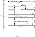
- An example for a 3GPP high-speed packet access (HSPA) system will now be presented with reference to FIG. 3 , illustrating an example of the radio protocol architecture for the user and control planes between the UE 210 and the Node B 208.
- the user plane or data plane carries user traffic
- the control plane carries control information, i.e., signaling.
- the radio protocol architecture for the UE 210 and Node B 208 is shown with three layers: Layer 1, Layer 2, and Layer 3.
- the UE 210 may have several upper layers above the L3 layer including a network layer (e.g., IP layer) that is terminated at a PDN gateway on the network side, and an application layer that is terminated at the other end of the connection (e.g., far end UE, server, etc.).
- a network layer e.g., IP layer
- an application layer that is terminated at the other end of the connection (e.g., far end UE, server, etc.).
- the RRC layer 316 handles control plane signaling between the UE 210 and the Node B 208.
- RRC layer 316 includes a number of functional entities for routing higher layer messages, handling broadcast and paging functions, establishing and configuring radio bearers, etc.
- the data link layer, called Layer 2 (L2 layer) 308 is between Layer 3 and the physical layer 306, and is responsible for the link between the UE 210 and Node B 208.
- the L2 layer 308 is split into sublayers.
- the L2 layer 308 includes two sublayers: a medium access control (MAC) sublayer 310 and a radio link control (RLC) sublayer 312.
- the L2 layer 308 additionally includes a packet data convergence protocol (PDCP) sublayer 314.
- PDCP packet data convergence protocol
- the PDCP sublayer 314 provides multiplexing between different radio bearers and logical channels.
- the PDCP sublayer 314 also provides header compression for upper layer data packets to reduce radio transmission overhead, security by ciphering the data packets, and handover support for UEs between Node Bs.
- the RLC sublayer 312 provides segmentation and reassembly of upper layer data packets, retransmission of lost data packets, and reordering of data packets to compensate for out-of-order reception due to a hybrid automatic repeat request (HARQ).
- HARQ hybrid automatic repeat request
- the MAC sublayer 310 provides multiplexing between logical channels and transport channels.
- the MAC sublayer 310 is also responsible for allocating the various radio resources (e.g., resource blocks) in one cell among the UEs.
- the MAC sublayer 310 is also responsible for HARQ operations.
- Layer 1 is the lowest layer and implements various physical layer signal processing functions. Layer 1 will be referred to herein as the physical layer (PHY) 306. At the PHY layer 306, the transport channels are mapped to different physical channels.
- PHY physical layer
- HSDPA downlink enhancements referred to as HSDPA.
- HSDPA utilizes as its transport channel the high-speed downlink shared channel (HS-DSCH).
- the HS-DSCH is implemented by three physical channels: the high-speed physical downlink shared channel (HS-PDSCH), the high-speed shared control channel (HS-SCCH), and the high-speed dedicated physical control channel (HS-DPCCH).
- the HS-DPCCH carries HARQ ACK/NACK signaling on the uplink to indicate whether a corresponding packet transmission was decoded successfully. That is, with respect to the downlink, the UE 210 provides feedback to the Node B 208 over the HS-DPCCH to indicate whether it correctly decoded a packet on the downlink.
- HS-DPCCH further includes feedback signaling from the UE 210 to assist the Node B 208 in taking the right decision in terms of modulation and coding scheme and precoding weight selection, this feedback signaling including the channel quality indicator (CQI) and precoding control information (PCI).
- CQI channel quality indicator
- PCI precoding control information
- EUL Enhanced Uplink
- HSUPA High Speed Uplink Packet Access
- E-DCH EUL Dedicated Channel
- the E-DCH is transmitted in the uplink together with the Release 99 DCH.
- the control portion of the DCH that is, the DPCCH, carries pilot bits and downlink power control commands on uplink transmissions.
- the DPCCH may be referred to as a control channel (e.g., a primary control channel) or a pilot channel (e.g., a primary pilot channel) in accordance with whether reference is being made to the channel's control aspects or its pilot aspects.
- the E-DCH is implemented by physical channels including the E-DCH Dedicated Physical Data Channel (E-DPDCH) and the E-DCH Dedicated Physical Control Channel (E-DPCCH).
- E-DPDCH E-DCH Dedicated Physical Data Channel
- E-DPCCH E-DCH Dedicated Physical Control Channel
- HSUPA relies on additional physical channels including the E-DCH HARQ Indicator Channel (E-HICH), the E-DCH Absolute Grant Channel (E-AGCH), and the E-DCH Relative Grant Channel (E-RGCH).
- E-HICH E-DCH HARQ Indicator Channel
- E-AGCH E-DCH Absolute Grant Channel
- E-RGCH E-DCH Relative Grant Channel
- a UE may be configured to employ a Dual-Channel High Speed Uplink Packet Access (DC-HSUPA).
- DC-HSUPA the physical channels may also include one or more of a Secondary E-DPDCH (S-E-DPDCH), a Secondary E-DPCCH (S-E-DPCCH), a Secondary DPCCH (S-DPCCH), and/or an EUL Rank and Offset Channel (E-ROCH).
- S-E-DPDCH Secondary E-DPDCH
- S-E-DPCCH Secondary E-DPCCH
- S-DPCCH Secondary DPCCH
- E-ROCH EUL Rank and Offset Channel
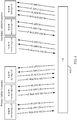
- FIG. 4 illustrates an example of a UE 402 employing DC-HSUPA according to at least one implementation.
- a UE 402 may operate with a primary active set on a primary uplink frequency (or primary uplink carrier) and a secondary active set on a secondary uplink frequency (or secondary uplink carrier).
- FIG. 4 also illustrates the various physical channels for the primary E-DCH and the secondary E-DCH.
- all scheduled data is prioritized by the UE for transmission on the secondary carrier, any remaining scheduled data should be transmitted on the primary carrier, and any non-scheduled data is only transmitted on the primary carrier.
- the downlink control channels corresponding to the secondary uplink carrier may be transmitted on the primary downlink carrier.
- the F-DPCH, E-AGCH, E-RGCH, and E-HICH channels are transmitted on the primary carrier, but affect the secondary uplink.
- Such a configuration can enable the UE to enter a discontinuous transmission (DTX) mode on the secondary uplink F-DPCH to reduce power consumption, can enable gain power saving due to less downlink control activities on the secondary carrier, and/or can reduce the need for out-of-sync procedures on the secondary carrier, as well as other benefits.
- DTX discontinuous transmission
- several optimizations achieved by such a configuration may be defeated as a result of the secondary carrier being used for scheduled data transmissions before the primary carrier.
- a DC-HSUPA User Equipment typically maps data resource blocks onto a scheduled flow and signaling resource blocks onto a non-scheduled flow.
- scheduled data flow mostly user traffic data
- scheduled data flow is first sent over the secondary uplink carrier, and then scheduled data flow is sent over the primary uplink carrier.
- Non-scheduled data flow is sent over the primary uplink carrier.
- the UE sends user traffic data as much as possible (and as soon as possible) on the secondary carrier.
- UEs can be configured to employ the primary carrier to uplink transmissions smaller than a predefined threshold.
- the UE can transmit a data transmission on the primary carrier for the first transmission time interval (TTI) including an indicator adapted to inform the network that the UE will be transmitting scheduled data over the secondary uplink carrier, with the primary uplink carrier used to send remaining data, if any.
- TTI transmission time interval
- FIG. 5 a block diagram is shown illustrating select components of a User Equipment (UE) 500 according to at least one example of the present disclosure.
- the UE 500 includes a processing circuit 502 coupled to or placed in electrical communication with a communications interface 504 and a storage medium 506.
- the processing circuit 502 includes circuitry arranged to obtain, process and/or send data, control data access and storage, issue commands, and control other desired operations.
- the processing circuit 502 may include circuitry configured to implement desired programming provided by appropriate media, and/or circuitry configured to perform one or more functions described in this disclosure.
- the processing circuit 502 may be implemented as one or more processors, one or more controllers, and/or other structure configured to execute executable programming.
- Examples of the processing circuit 502 may include a general purpose processor, a digital signal processor (DSP), an application specific integrated circuit (ASIC), a field programmable gate array (FPGA) or other programmable logic component, discrete gate or transistor logic, discrete hardware components, or any combination thereof designed to perform the functions described herein.
- DSP digital signal processor
- ASIC application specific integrated circuit
- FPGA field programmable gate array
- a general purpose processor may include a microprocessor, as well as any conventional processor, controller, microcontroller, or state machine.
- the processing circuit 502 may also be implemented as a combination of computing components, such as a combination of a DSP and a microprocessor, a number of microprocessors, one or more microprocessors in conjunction with a DSP core, an ASIC and a microprocessor, or any other number of varying configurations. These examples of the processing circuit 502 are for illustration and other suitable configurations within the scope of the present disclosure are also contemplated.
- the processing circuit 502 can include circuitry configured for processing data, including the execution of programming, which may be stored on the storage medium 506.
- programming shall be construed broadly to include without limitation instructions, instruction sets, code, code segments, program code, programs, subprograms, software modules, applications, software applications, software packages, routines, subroutines, objects, executables, threads of execution, procedures, functions, etc., whether referred to as software, firmware, middleware, microcode, hardware description language, or otherwise.
- the processing circuit 502 may include a dual-carrier uplink transmission circuit and/or module 508.
- the dual-carrier uplink transmission circuit/module 508 may include circuitry and/or programming (e.g., programming stored on the storage medium 506) configured to determine whether to use a primary carrier or a secondary carrier for uplink data transmissions sent by the UE 500.
- the communications interface 504 is configured to facilitate wireless communications of the UE 500.
- the communications interface 504 may include circuitry and/or programming configured to facilitate the communication of information bi-directionally with respect to one or more wireless network devices (e.g., network nodes).
- the communications interface 504 may be coupled to one or more antennas (not shown), and includes wireless transceiver circuitry, including at least one receiver circuit 508 (e.g., one or more receiver chains) and/or at least one transmitter circuit 510 (e.g., one or more transmitter chains).
- the storage medium 506 may represent one or more processor-readable devices for storing programming, such as processor executable code or instructions (e.g., software, firmware), electronic data, databases, or other digital information.
- the storage medium 506 may also be used for storing data that is manipulated by the processing circuit 502 when executing programming.
- the storage medium 506 may be any available media that can be accessed by a general purpose or special purpose processor, including portable or fixed storage devices, optical storage devices, and various other mediums capable of storing, containing and/or carrying programming.
- the storage medium 506 may include a processor-readable storage medium such as a magnetic storage device (e.g., hard disk, floppy disk, magnetic strip), an optical storage medium (e.g., compact disk (CD), digital versatile disk (DVD)), a smart card, a flash memory device (e.g., card, stick, key drive), random access memory (RAM), read only memory (ROM), programmable ROM (PROM), erasable PROM (EPROM), electrically erasable PROM (EEPROM), a register, a removable disk, and/or other mediums for storing programming, as well as any combination thereof.
- a processor-readable storage medium such as a magnetic storage device (e.g., hard disk, floppy disk, magnetic strip), an optical storage medium (e.g., compact disk (CD), digital versatile disk (DVD)), a smart card, a flash memory device (e.g., card, stick, key drive), random access memory (RAM), read only memory (ROM), programmable ROM (PROM),
- the storage medium 506 may be coupled to the processing circuit 502 such that the processing circuit 502 can read information from, and write information to, the storage medium 506. That is, the storage medium 506 can be coupled to the processing circuit 502 so that the storage medium 506 is at least accessible by the processing circuit 502, including examples where the storage medium 506 is integral to the processing circuit 502 and/or examples where the storage medium 506 is separate from the processing circuit 502 (e.g., resident in the UE 500, external to the UE 500, distributed across multiple entities).
- the storage medium 506 may include programming stored thereon. Such programming, when executed by the processing circuit 502, can cause the processing circuit 502 to perform one or more of the various functions and/or process steps described herein.
- the storage medium 506 may include dual-carrier uplink transmission operations 512.
- the dual-carrier uplink transmission operations 512 are configured to cause the processing circuit 502 to determine whether to use a primary carrier or a secondary carrier for uplink transmissions, as described herein.
- the processing circuit 502 is configured to perform (independently or in conjunction with the dual-carrier uplink transmission operations 512 on the storage medium 506) any or all of the processes, functions, steps and/or routines for any or all of the UEs described herein (e.g., access terminal 104, UE 210, UE 402, UE 500).
- the term "configured" in relation to the processing circuit 502 may refer to the processing circuit 502 being one or more of adapted, constructed, employed, implemented, and/or programmed (in conjunction with the dual-carrier uplink transmission operations 512) to perform a particular process, function, step and/or routine according to various features described herein.
- the UE 500 may be configured to employ two modes for determining which uplink carrier to employ to transmit user traffic data.
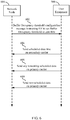
- FIG. 6 shows a flow diagram illustrating an example of a first mode of operation according to one implementation.
- the UE 500 may receive a transmission 602 from a network entity 604.
- the received transmission 602 may include an uplink transmission mode indicator instructing the UE 500 to employ legacy Release 9 DC-HSUPA operations.
- the indicator may be in the form of an instruction to set a data size or buffer occupancy threshold to zero (0).
- the indicator may be a configuration parameter for the buffer occupancy threshold, where the parameter is equal to zero (0) bytes.
- the received transmission 602 may be a buffer occupancy threshold configuration message indicating a buffer occupancy threshold of zero (0) to be employed by the UE 500.
- the UE 500 can be configured to send a predefined amount of scheduled data first on the secondary carrier at 606, and send any remaining scheduled data on the primary carrier at 608. Further, the UE can also be configured to send any non-scheduled data on the primary carrier.
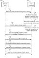
- FIG. 7 shows a flow diagram illustrating an example of a second mode of operation according to one implementation.
- the UE 500 may receive a transmission 702 from a network entity 704.
- the received transmission 702 may include an uplink transmission mode indicator instructing the UE 500 to employ an enhanced mode of DC-HSUPA operation.
- the indicator may include an instruction to set the data size or buffer occupancy threshold to a non-zero value.
- the received transmission 702 may be a buffer occupancy threshold configuration message indicating a buffer occupancy threshold to be employed by the UE 500.
- the UE 500 can set the threshold (e.g., the buffer occupancy threshold) to the indicated non-zero value at 706.
- the UE 500 can detect data in a buffer to be transmitted, where the data size is less than the threshold.
- the data is sent 710 by the UE 500 on the primary carrier.
- the UE 500 may at some point in time also, or alternatively, detect data 712 in the buffer to be transmitted, where the data size is greater than or equal to the threshold. In response to the data in the buffer being greater than or equal to the threshold, the UE 500 sends a first transmission time interval (TTI) 714 on the primary carrier with a scheduling information (SI) indicator adapted to inform the network entity 704 that the UE 500 is employing a legacy DC-HSUPA model for transmitting the current uplink data.
- TTI transmission time interval
- SI scheduling information
- the network node 704 may, in response to the scheduling information (SI) indicator, send a message 716 acknowledging the SI indicator.
- SI scheduling information
- the UE 500 may send scheduled data initially on the secondary carrier at 718, and any remaining scheduled data on the primary carrier 720. Further, the UE 500 can send non-scheduled data on the primary carrier 722.
- FIG. 8 is a flow diagram illustrating at least one example of a method operational on a UE, such as the UE 500.
- a UE 500 can determine whether a size of data to be transmitted is greater than or less than a predetermined threshold at step 802.
- the processing circuit 502 e.g., the dual-carrier uplink transmission circuit/module 508 may be configured to determine whether a size of uplink data is above or below a predetermined threshold.
- the predetermined threshold may be a buffer occupancy threshold.
- the processing circuit 502 e.g., the dual-carrier uplink transmission circuit/module 508 can be configured to determine whether a size of uplink data in a buffer (e.g., a buffer implemented by one or more components of the storage medium 506) is above or below the predetermined threshold.
- a buffer e.g., a buffer implemented by one or more components of the storage medium 506
- the value for the predetermined threshold can be received from the network.
- the predetermined threshold can be set to a value of zero (0) in some examples.
- the predetermined threshold can be set to a value greater than zero (0) in some examples.
- the UE 500 may transmit the data on a primary carrier when the size of the data is less than the predetermined threshold at 804.
- the processing circuit 502 e.g., the dual-carrier uplink transmission circuit/module 508 may be configured to transmit the data via the communications interface 504 on the primary carrier when the size of the data is less than the predetermined threshold. If the threshold is set to a value of zero (0), then the size of the data cannot be less than the predetermined threshold.
- the UE 500 may transmit a predetermined amount of the data initially on the secondary carrier, and any remaining portion of the data on the primary carrier when the size of the data is greater than or equal to the predetermined threshold.
- the processing circuit 502 e.g., the dual-carrier uplink transmission circuit/module 508
- the processing circuit 502 may be configured to transmit a predetermined amount of the data via the communications interface 504 on the secondary carrier when the size of the data in the buffer is greater than or equal to the predetermined threshold.
- any remaining amount of the data may be transmitted via the communications interface 504 on the primary carrier.
- the processing circuit 502 may be configured to transmit non-scheduled data via the communications interface 504 on the primary carrier when the size of the data is greater than or equal to the predetermined threshold.
- FIG. 9 is a flow diagram of at least one example of a process for implementing step 806 in FIG. 8 when the predetermined threshold is set to a value greater than zero (0).
- the processing circuit 502 e.g., the dual-carrier uplink transmission circuit/module 508 may be configured to transmit an indicator to inform the network of the uplink scheduling where the predetermined amount of data will be transmitted on the secondary carrier and any remaining data will be transmitted on the primary carrier.
- the indicator may be transmitted to the network on the first transmission time interval (TTI) on the primary carrier.
- TTI transmission time interval
- SI scheduling information
- the processing circuit 502 may be configured to receive an acknowledgement of the transmitted indicator from the network.
- the processing circuit 502 e.g., the dual-carrier uplink transmission circuit/module 508 may be configured to transmit the initial portion of scheduled data on the secondary carrier and any remaining portion of the scheduled data on the primary carrier, at step 906.
- FIGS. 1 , 2 , 3 , 4 , 5 , 6 , 7 , 8 , and/or 9 may be rearranged and/or combined into a single component, step, feature or function or embodied in several components, steps, or functions. Additional elements, components, steps, and/or functions may also be added or not utilized without departing from the present disclosure.
- the apparatus, devices and/or components illustrated in FIGS. 1 , 2 , 4 , and/or 5 may be configured to perform or employ one or more of the methods, features, parameters, and/or steps described in FIGS. 3 , 6 , 7 , 8 , and/or 9.
- the novel algorithms described herein may also be efficiently implemented in software and/or embedded in hardware.
Landscapes
- Engineering & Computer Science (AREA)
- Signal Processing (AREA)
- Computer Networks & Wireless Communication (AREA)
- Mobile Radio Communication Systems (AREA)
Applications Claiming Priority (3)
| Application Number | Priority Date | Filing Date | Title |
|---|---|---|---|
| US201462002123P | 2014-05-22 | 2014-05-22 | |
| US14/624,413 US9820179B2 (en) | 2014-05-22 | 2015-02-17 | Devices and methods for facilitating uplink transmissions on two or more carriers |
| PCT/US2015/028449 WO2015179096A1 (en) | 2014-05-22 | 2015-04-30 | Devices and methods for facilitating uplink transmissions on two or more carriers |
Publications (2)
| Publication Number | Publication Date |
|---|---|
| EP3146758A1 EP3146758A1 (en) | 2017-03-29 |
| EP3146758B1 true EP3146758B1 (en) | 2019-02-06 |
Family
ID=53190027
Family Applications (1)
| Application Number | Title | Priority Date | Filing Date |
|---|---|---|---|
| EP15723598.7A Not-in-force EP3146758B1 (en) | 2014-05-22 | 2015-04-30 | Devices and methods for facilitating uplink transmissions on two or more carriers |
Country Status (6)
| Country | Link |
|---|---|
| US (1) | US9820179B2 (enExample) |
| EP (1) | EP3146758B1 (enExample) |
| JP (1) | JP6385461B2 (enExample) |
| KR (1) | KR20170009861A (enExample) |
| CN (1) | CN106464471B (enExample) |
| WO (1) | WO2015179096A1 (enExample) |
Families Citing this family (5)
| Publication number | Priority date | Publication date | Assignee | Title |
|---|---|---|---|---|
| KR101969002B1 (ko) * | 2014-09-30 | 2019-08-13 | 후아웨이 테크놀러지 컴퍼니 리미티드 | 데이터 전송 방법 및 단말 |
| EP3322251B1 (en) * | 2015-08-19 | 2020-03-25 | Huawei Technologies Co., Ltd. | Data transmission method, device, and system |
| JP6480637B2 (ja) * | 2016-04-01 | 2019-03-13 | 京セラ株式会社 | 通信方法、プロセッサ、及びユーザ装置 |
| CN115665866A (zh) * | 2018-12-10 | 2023-01-31 | 华为技术有限公司 | 一种通信方法、装置及计算机可读存储介质 |
| CN111436089B (zh) * | 2019-01-11 | 2021-08-20 | 华为技术有限公司 | 通信的方法和装置 |
Citations (1)
| Publication number | Priority date | Publication date | Assignee | Title |
|---|---|---|---|---|
| US20100272078A1 (en) * | 2009-04-24 | 2010-10-28 | Interdigital Patent Holdings, Inc. | Method and apparatus for generating a radio link control protocol data unit for multi-carrier operation |
Family Cites Families (8)
| Publication number | Priority date | Publication date | Assignee | Title |
|---|---|---|---|---|
| JP5427893B2 (ja) * | 2008-10-31 | 2014-02-26 | インターデイジタル パテント ホールディングス インコーポレイテッド | 複数のアップリンク搬送波を使用するアップリンク送信の処理 |
| US8842613B2 (en) * | 2009-02-09 | 2014-09-23 | Qualcomm Incorporated | Power allocation in multi-carrier enhanced uplink |
| KR101470063B1 (ko) * | 2009-03-12 | 2014-12-12 | 인터디지탈 패튼 홀딩스, 인크 | 업링크 일차 반송파를 선택 및 재선택하는 방법 및 장치 |
| US7826370B1 (en) | 2009-04-29 | 2010-11-02 | Sprint Spectrum L.P. | Dynamic payload-size threshold for triggering an auxiliary pilot |
| KR20110020195A (ko) * | 2009-08-21 | 2011-03-02 | 엘지전자 주식회사 | 복수의 상향링크 주파수 상으로 데이터 블록 전송 방법 및 장치 |
| WO2011099151A1 (ja) * | 2010-02-12 | 2011-08-18 | 富士通株式会社 | 無線通信装置、無線通信システムおよび無線通信方法 |
| US9137841B2 (en) * | 2011-10-03 | 2015-09-15 | Mediatek Inc. | Enhancement for scheduling request triggering based on traffic condition |
| US9608899B2 (en) | 2011-11-21 | 2017-03-28 | Qualcomm Incorporated | Packet-based aggregation of data streams across disparate networking interfaces |
-
2015
- 2015-02-17 US US14/624,413 patent/US9820179B2/en not_active Expired - Fee Related
- 2015-04-30 CN CN201580025509.4A patent/CN106464471B/zh not_active Expired - Fee Related
- 2015-04-30 EP EP15723598.7A patent/EP3146758B1/en not_active Not-in-force
- 2015-04-30 JP JP2016568398A patent/JP6385461B2/ja not_active Expired - Fee Related
- 2015-04-30 KR KR1020167031906A patent/KR20170009861A/ko not_active Withdrawn
- 2015-04-30 WO PCT/US2015/028449 patent/WO2015179096A1/en not_active Ceased
Patent Citations (1)
| Publication number | Priority date | Publication date | Assignee | Title |
|---|---|---|---|---|
| US20100272078A1 (en) * | 2009-04-24 | 2010-10-28 | Interdigital Patent Holdings, Inc. | Method and apparatus for generating a radio link control protocol data unit for multi-carrier operation |
Also Published As
| Publication number | Publication date |
|---|---|
| JP2017519429A (ja) | 2017-07-13 |
| EP3146758A1 (en) | 2017-03-29 |
| JP6385461B2 (ja) | 2018-09-05 |
| CN106464471A (zh) | 2017-02-22 |
| CN106464471B (zh) | 2020-03-13 |
| WO2015179096A1 (en) | 2015-11-26 |
| US20150341823A1 (en) | 2015-11-26 |
| US9820179B2 (en) | 2017-11-14 |
| KR20170009861A (ko) | 2017-01-25 |
Similar Documents
| Publication | Publication Date | Title |
|---|---|---|
| US9313756B2 (en) | Apparatus and methods for managing hyper frame number (HFN) de-synchronization in radio link control (RLC) unacknowledged mode (UM) | |
| US20150085749A1 (en) | Mechanism to exchange proprietary signaling messages between a ue and a network | |
| EP3028496B1 (en) | Apparatus and method of managing signaling radio bearer transmissions at a user equipment | |
| CN104094657B (zh) | 用于增强型蜂窝小区前向接入信道专用信道中的信道回退的方法和装置 | |
| US20150071081A1 (en) | Apparatuses and methods for uplink power control in wireless communication | |
| EP3146758B1 (en) | Devices and methods for facilitating uplink transmissions on two or more carriers | |
| WO2014209640A1 (en) | Apparatus and method for dynamic user equipment capability reporting based on data activity | |
| WO2014137753A1 (en) | Prioritizing time critical data for transmission during power-limited state in dc-hsupa operation | |
| JP6563479B2 (ja) | ワイヤレス通信において送信電力割振りを最適化するための技法 | |
| EP3120661B1 (en) | Continuous packet connectivity (cpc) with dedicated channel (dch) enhancements | |
| US20160242185A1 (en) | Power allocation for non-scheduled transmission over dual carrier hsupa | |
| US9444753B2 (en) | Methods and apparatus for improving call performance and data throughput | |
| US20160007404A1 (en) | Discontinuous reception techniques |
Legal Events
| Date | Code | Title | Description |
|---|---|---|---|
| STAA | Information on the status of an ep patent application or granted ep patent |
Free format text: STATUS: THE INTERNATIONAL PUBLICATION HAS BEEN MADE |
|
| PUAI | Public reference made under article 153(3) epc to a published international application that has entered the european phase |
Free format text: ORIGINAL CODE: 0009012 |
|
| STAA | Information on the status of an ep patent application or granted ep patent |
Free format text: STATUS: REQUEST FOR EXAMINATION WAS MADE |
|
| 17P | Request for examination filed |
Effective date: 20161024 |
|
| AK | Designated contracting states |
Kind code of ref document: A1 Designated state(s): AL AT BE BG CH CY CZ DE DK EE ES FI FR GB GR HR HU IE IS IT LI LT LU LV MC MK MT NL NO PL PT RO RS SE SI SK SM TR |
|
| AX | Request for extension of the european patent |
Extension state: BA ME |
|
| DAV | Request for validation of the european patent (deleted) | ||
| DAX | Request for extension of the european patent (deleted) | ||
| STAA | Information on the status of an ep patent application or granted ep patent |
Free format text: STATUS: EXAMINATION IS IN PROGRESS |
|
| 17Q | First examination report despatched |
Effective date: 20171218 |
|
| GRAP | Despatch of communication of intention to grant a patent |
Free format text: ORIGINAL CODE: EPIDOSNIGR1 |
|
| STAA | Information on the status of an ep patent application or granted ep patent |
Free format text: STATUS: GRANT OF PATENT IS INTENDED |
|
| RIC1 | Information provided on ipc code assigned before grant |
Ipc: H04W 28/02 20090101ALI20180720BHEP Ipc: H04W 28/08 20090101AFI20180720BHEP |
|
| INTG | Intention to grant announced |
Effective date: 20180806 |
|
| GRAS | Grant fee paid |
Free format text: ORIGINAL CODE: EPIDOSNIGR3 |
|
| GRAA | (expected) grant |
Free format text: ORIGINAL CODE: 0009210 |
|
| STAA | Information on the status of an ep patent application or granted ep patent |
Free format text: STATUS: THE PATENT HAS BEEN GRANTED |
|
| AK | Designated contracting states |
Kind code of ref document: B1 Designated state(s): AL AT BE BG CH CY CZ DE DK EE ES FI FR GB GR HR HU IE IS IT LI LT LU LV MC MK MT NL NO PL PT RO RS SE SI SK SM TR |
|
| REG | Reference to a national code |
Ref country code: GB Ref legal event code: FG4D |
|
| REG | Reference to a national code |
Ref country code: CH Ref legal event code: EP Ref country code: AT Ref legal event code: REF Ref document number: 1095640 Country of ref document: AT Kind code of ref document: T Effective date: 20190215 |
|
| REG | Reference to a national code |
Ref country code: IE Ref legal event code: FG4D |
|
| REG | Reference to a national code |
Ref country code: DE Ref legal event code: R096 Ref document number: 602015024346 Country of ref document: DE |
|
| REG | Reference to a national code |
Ref country code: NL Ref legal event code: MP Effective date: 20190206 |
|
| REG | Reference to a national code |
Ref country code: LT Ref legal event code: MG4D |
|
| PG25 | Lapsed in a contracting state [announced via postgrant information from national office to epo] |
Ref country code: PT Free format text: LAPSE BECAUSE OF FAILURE TO SUBMIT A TRANSLATION OF THE DESCRIPTION OR TO PAY THE FEE WITHIN THE PRESCRIBED TIME-LIMIT Effective date: 20190606 Ref country code: LT Free format text: LAPSE BECAUSE OF FAILURE TO SUBMIT A TRANSLATION OF THE DESCRIPTION OR TO PAY THE FEE WITHIN THE PRESCRIBED TIME-LIMIT Effective date: 20190206 Ref country code: NL Free format text: LAPSE BECAUSE OF FAILURE TO SUBMIT A TRANSLATION OF THE DESCRIPTION OR TO PAY THE FEE WITHIN THE PRESCRIBED TIME-LIMIT Effective date: 20190206 Ref country code: SE Free format text: LAPSE BECAUSE OF FAILURE TO SUBMIT A TRANSLATION OF THE DESCRIPTION OR TO PAY THE FEE WITHIN THE PRESCRIBED TIME-LIMIT Effective date: 20190206 Ref country code: NO Free format text: LAPSE BECAUSE OF FAILURE TO SUBMIT A TRANSLATION OF THE DESCRIPTION OR TO PAY THE FEE WITHIN THE PRESCRIBED TIME-LIMIT Effective date: 20190506 Ref country code: FI Free format text: LAPSE BECAUSE OF FAILURE TO SUBMIT A TRANSLATION OF THE DESCRIPTION OR TO PAY THE FEE WITHIN THE PRESCRIBED TIME-LIMIT Effective date: 20190206 |
|
| REG | Reference to a national code |
Ref country code: AT Ref legal event code: MK05 Ref document number: 1095640 Country of ref document: AT Kind code of ref document: T Effective date: 20190206 |
|
| PG25 | Lapsed in a contracting state [announced via postgrant information from national office to epo] |
Ref country code: HR Free format text: LAPSE BECAUSE OF FAILURE TO SUBMIT A TRANSLATION OF THE DESCRIPTION OR TO PAY THE FEE WITHIN THE PRESCRIBED TIME-LIMIT Effective date: 20190206 Ref country code: GR Free format text: LAPSE BECAUSE OF FAILURE TO SUBMIT A TRANSLATION OF THE DESCRIPTION OR TO PAY THE FEE WITHIN THE PRESCRIBED TIME-LIMIT Effective date: 20190507 Ref country code: LV Free format text: LAPSE BECAUSE OF FAILURE TO SUBMIT A TRANSLATION OF THE DESCRIPTION OR TO PAY THE FEE WITHIN THE PRESCRIBED TIME-LIMIT Effective date: 20190206 Ref country code: RS Free format text: LAPSE BECAUSE OF FAILURE TO SUBMIT A TRANSLATION OF THE DESCRIPTION OR TO PAY THE FEE WITHIN THE PRESCRIBED TIME-LIMIT Effective date: 20190206 Ref country code: BG Free format text: LAPSE BECAUSE OF FAILURE TO SUBMIT A TRANSLATION OF THE DESCRIPTION OR TO PAY THE FEE WITHIN THE PRESCRIBED TIME-LIMIT Effective date: 20190506 Ref country code: IS Free format text: LAPSE BECAUSE OF FAILURE TO SUBMIT A TRANSLATION OF THE DESCRIPTION OR TO PAY THE FEE WITHIN THE PRESCRIBED TIME-LIMIT Effective date: 20190606 |
|
| PG25 | Lapsed in a contracting state [announced via postgrant information from national office to epo] |
Ref country code: SK Free format text: LAPSE BECAUSE OF FAILURE TO SUBMIT A TRANSLATION OF THE DESCRIPTION OR TO PAY THE FEE WITHIN THE PRESCRIBED TIME-LIMIT Effective date: 20190206 Ref country code: ES Free format text: LAPSE BECAUSE OF FAILURE TO SUBMIT A TRANSLATION OF THE DESCRIPTION OR TO PAY THE FEE WITHIN THE PRESCRIBED TIME-LIMIT Effective date: 20190206 Ref country code: AL Free format text: LAPSE BECAUSE OF FAILURE TO SUBMIT A TRANSLATION OF THE DESCRIPTION OR TO PAY THE FEE WITHIN THE PRESCRIBED TIME-LIMIT Effective date: 20190206 Ref country code: CZ Free format text: LAPSE BECAUSE OF FAILURE TO SUBMIT A TRANSLATION OF THE DESCRIPTION OR TO PAY THE FEE WITHIN THE PRESCRIBED TIME-LIMIT Effective date: 20190206 Ref country code: DK Free format text: LAPSE BECAUSE OF FAILURE TO SUBMIT A TRANSLATION OF THE DESCRIPTION OR TO PAY THE FEE WITHIN THE PRESCRIBED TIME-LIMIT Effective date: 20190206 Ref country code: IT Free format text: LAPSE BECAUSE OF FAILURE TO SUBMIT A TRANSLATION OF THE DESCRIPTION OR TO PAY THE FEE WITHIN THE PRESCRIBED TIME-LIMIT Effective date: 20190206 Ref country code: EE Free format text: LAPSE BECAUSE OF FAILURE TO SUBMIT A TRANSLATION OF THE DESCRIPTION OR TO PAY THE FEE WITHIN THE PRESCRIBED TIME-LIMIT Effective date: 20190206 Ref country code: RO Free format text: LAPSE BECAUSE OF FAILURE TO SUBMIT A TRANSLATION OF THE DESCRIPTION OR TO PAY THE FEE WITHIN THE PRESCRIBED TIME-LIMIT Effective date: 20190206 |
|
| REG | Reference to a national code |
Ref country code: DE Ref legal event code: R097 Ref document number: 602015024346 Country of ref document: DE |
|
| PG25 | Lapsed in a contracting state [announced via postgrant information from national office to epo] |
Ref country code: SM Free format text: LAPSE BECAUSE OF FAILURE TO SUBMIT A TRANSLATION OF THE DESCRIPTION OR TO PAY THE FEE WITHIN THE PRESCRIBED TIME-LIMIT Effective date: 20190206 Ref country code: PL Free format text: LAPSE BECAUSE OF FAILURE TO SUBMIT A TRANSLATION OF THE DESCRIPTION OR TO PAY THE FEE WITHIN THE PRESCRIBED TIME-LIMIT Effective date: 20190206 |
|
| REG | Reference to a national code |
Ref country code: CH Ref legal event code: PL |
|
| PLBE | No opposition filed within time limit |
Free format text: ORIGINAL CODE: 0009261 |
|
| STAA | Information on the status of an ep patent application or granted ep patent |
Free format text: STATUS: NO OPPOSITION FILED WITHIN TIME LIMIT |
|
| REG | Reference to a national code |
Ref country code: BE Ref legal event code: MM Effective date: 20190430 |
|
| PG25 | Lapsed in a contracting state [announced via postgrant information from national office to epo] |
Ref country code: AT Free format text: LAPSE BECAUSE OF FAILURE TO SUBMIT A TRANSLATION OF THE DESCRIPTION OR TO PAY THE FEE WITHIN THE PRESCRIBED TIME-LIMIT Effective date: 20190206 Ref country code: MC Free format text: LAPSE BECAUSE OF FAILURE TO SUBMIT A TRANSLATION OF THE DESCRIPTION OR TO PAY THE FEE WITHIN THE PRESCRIBED TIME-LIMIT Effective date: 20190206 Ref country code: LU Free format text: LAPSE BECAUSE OF NON-PAYMENT OF DUE FEES Effective date: 20190430 |
|
| 26N | No opposition filed |
Effective date: 20191107 |
|
| PG25 | Lapsed in a contracting state [announced via postgrant information from national office to epo] |
Ref country code: LI Free format text: LAPSE BECAUSE OF NON-PAYMENT OF DUE FEES Effective date: 20190430 Ref country code: CH Free format text: LAPSE BECAUSE OF NON-PAYMENT OF DUE FEES Effective date: 20190430 |
|
| PG25 | Lapsed in a contracting state [announced via postgrant information from national office to epo] |
Ref country code: BE Free format text: LAPSE BECAUSE OF NON-PAYMENT OF DUE FEES Effective date: 20190430 Ref country code: SI Free format text: LAPSE BECAUSE OF FAILURE TO SUBMIT A TRANSLATION OF THE DESCRIPTION OR TO PAY THE FEE WITHIN THE PRESCRIBED TIME-LIMIT Effective date: 20190206 |
|
| PG25 | Lapsed in a contracting state [announced via postgrant information from national office to epo] |
Ref country code: TR Free format text: LAPSE BECAUSE OF FAILURE TO SUBMIT A TRANSLATION OF THE DESCRIPTION OR TO PAY THE FEE WITHIN THE PRESCRIBED TIME-LIMIT Effective date: 20190206 |
|
| PG25 | Lapsed in a contracting state [announced via postgrant information from national office to epo] |
Ref country code: IE Free format text: LAPSE BECAUSE OF NON-PAYMENT OF DUE FEES Effective date: 20190430 |
|
| PGFP | Annual fee paid to national office [announced via postgrant information from national office to epo] |
Ref country code: GB Payment date: 20200327 Year of fee payment: 6 |
|
| PGFP | Annual fee paid to national office [announced via postgrant information from national office to epo] |
Ref country code: FR Payment date: 20200320 Year of fee payment: 6 |
|
| PGFP | Annual fee paid to national office [announced via postgrant information from national office to epo] |
Ref country code: DE Payment date: 20200317 Year of fee payment: 6 |
|
| PG25 | Lapsed in a contracting state [announced via postgrant information from national office to epo] |
Ref country code: CY Free format text: LAPSE BECAUSE OF FAILURE TO SUBMIT A TRANSLATION OF THE DESCRIPTION OR TO PAY THE FEE WITHIN THE PRESCRIBED TIME-LIMIT Effective date: 20190206 |
|
| PG25 | Lapsed in a contracting state [announced via postgrant information from national office to epo] |
Ref country code: MT Free format text: LAPSE BECAUSE OF FAILURE TO SUBMIT A TRANSLATION OF THE DESCRIPTION OR TO PAY THE FEE WITHIN THE PRESCRIBED TIME-LIMIT Effective date: 20190206 Ref country code: HU Free format text: LAPSE BECAUSE OF FAILURE TO SUBMIT A TRANSLATION OF THE DESCRIPTION OR TO PAY THE FEE WITHIN THE PRESCRIBED TIME-LIMIT; INVALID AB INITIO Effective date: 20150430 |
|
| REG | Reference to a national code |
Ref country code: DE Ref legal event code: R119 Ref document number: 602015024346 Country of ref document: DE |
|
| GBPC | Gb: european patent ceased through non-payment of renewal fee |
Effective date: 20210430 |
|
| PG25 | Lapsed in a contracting state [announced via postgrant information from national office to epo] |
Ref country code: FR Free format text: LAPSE BECAUSE OF NON-PAYMENT OF DUE FEES Effective date: 20210430 Ref country code: GB Free format text: LAPSE BECAUSE OF NON-PAYMENT OF DUE FEES Effective date: 20210430 Ref country code: DE Free format text: LAPSE BECAUSE OF NON-PAYMENT OF DUE FEES Effective date: 20211103 |
|
| PG25 | Lapsed in a contracting state [announced via postgrant information from national office to epo] |
Ref country code: MK Free format text: LAPSE BECAUSE OF FAILURE TO SUBMIT A TRANSLATION OF THE DESCRIPTION OR TO PAY THE FEE WITHIN THE PRESCRIBED TIME-LIMIT Effective date: 20190206 |