EP3146228B1 - Brake support - Google Patents
Brake support Download PDFInfo
- Publication number
- EP3146228B1 EP3146228B1 EP15723909.6A EP15723909A EP3146228B1 EP 3146228 B1 EP3146228 B1 EP 3146228B1 EP 15723909 A EP15723909 A EP 15723909A EP 3146228 B1 EP3146228 B1 EP 3146228B1
- Authority
- EP
- European Patent Office
- Prior art keywords
- engagement
- axis
- support unit
- flange portion
- guiding
- Prior art date
- Legal status (The legal status is an assumption and is not a legal conclusion. Google has not performed a legal analysis and makes no representation as to the accuracy of the status listed.)
- Active
Links
- 230000014759 maintenance of location Effects 0.000 claims 7
- 230000005540 biological transmission Effects 0.000 description 4
- 230000002349 favourable effect Effects 0.000 description 4
- 229910001141 Ductile iron Inorganic materials 0.000 description 3
- 238000005452 bending Methods 0.000 description 3
- 230000008901 benefit Effects 0.000 description 3
- 239000007788 liquid Substances 0.000 description 3
- 238000005266 casting Methods 0.000 description 2
- 230000000694 effects Effects 0.000 description 2
- 239000007787 solid Substances 0.000 description 2
- 230000007480 spreading Effects 0.000 description 2
- 238000003892 spreading Methods 0.000 description 2
- 230000035882 stress Effects 0.000 description 2
- 239000000725 suspension Substances 0.000 description 2
- 238000003466 welding Methods 0.000 description 2
- 229910001018 Cast iron Inorganic materials 0.000 description 1
- 230000015572 biosynthetic process Effects 0.000 description 1
- 238000010276 construction Methods 0.000 description 1
- 238000005520 cutting process Methods 0.000 description 1
- 230000001419 dependent effect Effects 0.000 description 1
- 238000006073 displacement reaction Methods 0.000 description 1
- 230000006872 improvement Effects 0.000 description 1
- 238000009434 installation Methods 0.000 description 1
- 238000004519 manufacturing process Methods 0.000 description 1
- 239000000463 material Substances 0.000 description 1
- 230000007246 mechanism Effects 0.000 description 1
- 230000009467 reduction Effects 0.000 description 1
- 239000011343 solid material Substances 0.000 description 1
- 230000008646 thermal stress Effects 0.000 description 1
- 230000007704 transition Effects 0.000 description 1
Images
Classifications
-
- B—PERFORMING OPERATIONS; TRANSPORTING
- B60—VEHICLES IN GENERAL
- B60T—VEHICLE BRAKE CONTROL SYSTEMS OR PARTS THEREOF; BRAKE CONTROL SYSTEMS OR PARTS THEREOF, IN GENERAL; ARRANGEMENT OF BRAKING ELEMENTS ON VEHICLES IN GENERAL; PORTABLE DEVICES FOR PREVENTING UNWANTED MOVEMENT OF VEHICLES; VEHICLE MODIFICATIONS TO FACILITATE COOLING OF BRAKES
- B60T17/00—Component parts, details, or accessories of power brake systems not covered by groups B60T8/00, B60T13/00 or B60T15/00, or presenting other characteristic features
- B60T17/08—Brake cylinders other than ultimate actuators
- B60T17/088—Mounting arrangements
-
- F—MECHANICAL ENGINEERING; LIGHTING; HEATING; WEAPONS; BLASTING
- F16—ENGINEERING ELEMENTS AND UNITS; GENERAL MEASURES FOR PRODUCING AND MAINTAINING EFFECTIVE FUNCTIONING OF MACHINES OR INSTALLATIONS; THERMAL INSULATION IN GENERAL
- F16D—COUPLINGS FOR TRANSMITTING ROTATION; CLUTCHES; BRAKES
- F16D65/00—Parts or details
- F16D65/02—Braking members; Mounting thereof
-
- B—PERFORMING OPERATIONS; TRANSPORTING
- B60—VEHICLES IN GENERAL
- B60T—VEHICLE BRAKE CONTROL SYSTEMS OR PARTS THEREOF; BRAKE CONTROL SYSTEMS OR PARTS THEREOF, IN GENERAL; ARRANGEMENT OF BRAKING ELEMENTS ON VEHICLES IN GENERAL; PORTABLE DEVICES FOR PREVENTING UNWANTED MOVEMENT OF VEHICLES; VEHICLE MODIFICATIONS TO FACILITATE COOLING OF BRAKES
- B60T1/00—Arrangements of braking elements, i.e. of those parts where braking effect occurs specially for vehicles
-
- B—PERFORMING OPERATIONS; TRANSPORTING
- B60—VEHICLES IN GENERAL
- B60T—VEHICLE BRAKE CONTROL SYSTEMS OR PARTS THEREOF; BRAKE CONTROL SYSTEMS OR PARTS THEREOF, IN GENERAL; ARRANGEMENT OF BRAKING ELEMENTS ON VEHICLES IN GENERAL; PORTABLE DEVICES FOR PREVENTING UNWANTED MOVEMENT OF VEHICLES; VEHICLE MODIFICATIONS TO FACILITATE COOLING OF BRAKES
- B60T17/00—Component parts, details, or accessories of power brake systems not covered by groups B60T8/00, B60T13/00 or B60T15/00, or presenting other characteristic features
-
- F—MECHANICAL ENGINEERING; LIGHTING; HEATING; WEAPONS; BLASTING
- F16—ENGINEERING ELEMENTS AND UNITS; GENERAL MEASURES FOR PRODUCING AND MAINTAINING EFFECTIVE FUNCTIONING OF MACHINES OR INSTALLATIONS; THERMAL INSULATION IN GENERAL
- F16D—COUPLINGS FOR TRANSMITTING ROTATION; CLUTCHES; BRAKES
- F16D51/00—Brakes with outwardly-movable braking members co-operating with the inner surface of a drum or the like
-
- F—MECHANICAL ENGINEERING; LIGHTING; HEATING; WEAPONS; BLASTING
- F16—ENGINEERING ELEMENTS AND UNITS; GENERAL MEASURES FOR PRODUCING AND MAINTAINING EFFECTIVE FUNCTIONING OF MACHINES OR INSTALLATIONS; THERMAL INSULATION IN GENERAL
- F16D—COUPLINGS FOR TRANSMITTING ROTATION; CLUTCHES; BRAKES
- F16D65/00—Parts or details
- F16D65/005—Components of axially engaging brakes not otherwise provided for
- F16D65/0056—Brake supports
-
- F—MECHANICAL ENGINEERING; LIGHTING; HEATING; WEAPONS; BLASTING
- F16—ENGINEERING ELEMENTS AND UNITS; GENERAL MEASURES FOR PRODUCING AND MAINTAINING EFFECTIVE FUNCTIONING OF MACHINES OR INSTALLATIONS; THERMAL INSULATION IN GENERAL
- F16D—COUPLINGS FOR TRANSMITTING ROTATION; CLUTCHES; BRAKES
- F16D51/00—Brakes with outwardly-movable braking members co-operating with the inner surface of a drum or the like
- F16D2051/001—Parts or details of drum brakes
- F16D2051/003—Brake supports
Definitions
- the present invention relates to a carrier unit for use in brake systems of motor vehicles, preferably of commercial vehicles.
- Carrier units are known from the prior art in that usually cast brake carrier are provided on which the various components of the vehicle brake can be fixed and connected via the brake carrier with, for example, the axis.
- the known from the prior art brake carrier in this case generally have the disadvantage that they are heavy-built and require a high installation cost due to a variety of components to be mounted.
- these additional adapter elements increase the space requirement and, on the other hand, also create a multiplicity of vulnerable connection points through which, for example, dirt and liquids can reach the interior region of the expanding wedge unit. There is therefore a significant need for improvement with regard to the compactness, the susceptibility to errors and the assembly of a brake system.
- the WO 2013/087737 A1 shows a brake carrier of a drum brake with a carrier unit, which has a first connection portion, on which a brake cylinder can be fixed and has a second connection portion, on which a converter unit can be fixed.
- the US 5,613,577 A shows a disc brake of a vehicle which is hydraulically actuated.
- Object of the present invention is to provide a carrier unit, which simplifies both the assembly of the brake system and saves weight and space and reduces the susceptibility of the brake system to failure.
- the carrier unit comprises a first flange portion, a second flange portion and a guide portion, wherein the first flange portion has a first engagement geometry for fixing the carrier unit to a chassis, wherein the second flange portion has a second engagement geometry for fixing a brake cylinder, wherein the guide portion adjacent to the second Flange portion is arranged and has a guide geometry for guiding a guide member along a guide axis, wherein a Sp Drkeilica adjacent to the guide portion is provided and wherein the Sp lanternkeilhow comprises a housing which is integrally formed with the guide portion.
- an expansion wedge unit is formed integrally with the support unit, wherein in particular the housing of the expansion wedge unit is formed integrally with the corresponding adjacent portion of the support unit. Adjacent to the housing of the carrier unit while the guide portion of the carrier unit is provided.
- the guide section is an at least partially hollow-body-shaped section of the carrier unit, in which a guide element is arranged to be displaceable along a guide axis.
- the guide element particularly preferably serves for the transmission of force of a braking force which leads from a brake cylinder flanged to the second flange section to a corresponding expanding wedge mechanism which is arranged in the expanding wedge unit.
- the guide section also has the function of both the geometry of the expanding wedge unit and the guide element and to shield the brake cylinder against the ingress of dirt, debris and liquids.
- the first flange portion has a first engagement geometry for fixing the carrier unit to a running gear, wherein the first engagement geometry is preferably a standardized engagement geometry, which is engageable by default on trolleys of various commercial vehicles or commercial vehicle types.
- the second engagement geometry of the second flange portion is also a standardized interface for fixing a brake cylinder, which is characterized in particular by preferably two engagement geometries, which are provided at a certain, standardized distance from each other.
- the carrier unit can therefore be integrated into existing brake systems, wherein the previously used brake cylinder can be further applied.
- the second flange portion is formed integrally with the guide portion.
- the second flange portion is preferably formed as a one-piece casting together with the guide portion, which advantageously a subsequent assembly of the second flange on the guide portion can be avoided while wall or cross-sectional geometries can be used, which is a particularly good power transmission at the same time Allow wall thickness. Due to the one-piece design of the second flange portion and the guide portion while the weight of the support unit can be reduced and the assembly costs for attaching a brake cylinder to the support unit can be significantly reduced because a fitter must handle only one component.
- the carrier unit has a holding section, which adjoins the first flange section and the guide section and extends substantially along a holding axis, wherein the first flange section, the holding section and the guide portion are formed integrally with each other.
- the holding section preferably serves to position the guide section and thus also the first flange section preferably integrally connected to the guide section and the expanding wedge unit preferably integrally connected to the guide section relative to the chassis.
- the holding portion preferably has an extension along a holding axis, wherein the extension of the holding portion along the holding axis, or parallel to the holding axis is preferably its largest extension.
- force-optimized outer geometries of the holding section are provided, that is to say preferably rounded outer geometries on which advantageously only low notch effect occurs under bending stress of the first flange section and of the holding section.
- the holding axis is transverse, preferably perpendicular to the guide axis.
- an accurate positioning of the power transmission direction from the brake cylinder is defined for Sp Drkeiltician.
- the vertical alignment of the holding portion with its holding axis and the guide portion with the guide axis to each other particularly preferably provides for a uniform force transmission under bending stress, which are transmitted by the relatively heavy brake cylinder on the carrier unit or which are transmitted by vibrations, for example, the brake shoes on the Sp Drssenkeiltician.
- the first engagement geometry extends substantially along an engagement axis, wherein the support axis is pivoted at an angle to the engagement axis and wherein the angle is smaller than 90 °. It is further preferred that the engagement axis, along which the engagement geometry extends or along which the engagement geometry can be advantageously brought into engagement with the chassis of a commercial vehicle, substantially parallel is arranged to an axial direction of the chassis, for example, parallel to the direction of rotation of the vehicle wheels.
- substantially parallel in the context of the present invention means that smaller deviations, for example caused by manufacturing tolerances, are considered parallel in the context of the present invention.
- the carrier unit along the engagement axis which extends parallel to the axial direction with advantage, fixed to the chassis of the commercial vehicle, in particular preferably a good accessibility of the corresponding fastening means along the engagement axis is given.
- the holding axis is pivoted at an angle to the engagement axis, said angle being less than 90 °.
- the angle is measured on the side of the carrier unit on which the expanding wedge unit is located.
- the holding axis By arranging the holding axis obliquely relative to the engagement axis, it is possible to allow the upper part of the carrier unit, that is to say the area consisting of expanding wedge unit, guide section and second flange section, to protrude into the interior of a brake drum, in order to engage the expanding wedge unit in each case To be able to bring brake shoes.
- the brake cylinder is arranged at a sufficient distance from the axis of the commercial vehicle by the oblique arrangement of the holding axis, so that no vibrations due to vibrations and occurring contact between the brake cylinder and adjacent geometries of the chassis occur in vibrations in the suspension system.
- the angle between the engagement axis and the support axis is determined as an angle between the projections of the engagement axis and the support axis on a, preferably through the guide portion extending cutting plane ,
- the angle is in the range of 45 ° to 89 °, preferably in the range of 60 ° to 85 ° and more preferably about 70 ° to 85 °.
- the relatively wide range of 45 ° to 89 ° is preferred for carrier units, which are designed to set especially many different brake cylinder. It has been found that in this range from 45 ° to 89 ° all present on the market brake cylinder can be readily integrated into a brake system with a carrier unit according to the invention, without having to fear damage by striking adjacent chassis geometries.
- the particularly preferred range of 60 ° to 85 ° has proven to be advantageous, since in this way a particularly compact design of the carrier unit is achieved, on the one hand, a sufficient distance of a fixed to the second flange brake cylinder is ensured by the adjacent chassis geometries and on the other hand Extension of the holding section can be chosen relatively small and in this way weight can be saved.
- the particularly preferred range of 70 ° to 85 ° has proven to be advantageous for use with Sp Drokkeilbremsakuen, since an optimal arrangement of the upper portion of the support unit relative to the first engagement geometry or relative to the first flange is reached, on the one hand with weight savings, on the other hand with a as simple as possible to integrate a carrier unit in the braking system of a commercial vehicle.
- the first engagement geometry can be brought indirectly and / or directly into positive engagement with a corresponding section of the chassis.
- An indirect positive engagement is particularly preferably produced by a bolt or a screw connection.
- a direct form-fitting engagement can preferably be made by a projection on the first flange portion or the first engagement geometry, which engages positively in a corresponding recess geometry on the corresponding portion of the chassis to secure, for example, the carrier unit relative to the chassis against rotation about the engagement axis.
- a positive connection of the carrier unit to the chassis is preferred to firstly to ensure disassembly of the carrier unit from the chassis and on the other hand to avoid the occurring at a usual welding joint of the brake carrier to the suspension axle thermal stresses and structural damage.
- a securing element which can be brought along the engagement axis in positive engagement with the first engagement geometry, the securing element being accessible from the side of the carrier unit the spreading wedge unit is located.
- the securing element is preferably a screw or a threaded bolt and is advantageously accessible from the side of the carrier unit on which the expanding wedge unit is located.
- the securing element is preferably accessible from the outside of the chassis, that is, after the wheel and the brake drum of the brake unit have been removed from the chassis, the carrier unit can be removed by loosening the securing element from the outside in a simple manner.
- the securing element may also be designed as a nut, which can be brought into engagement with a first engagement geometry designed, for example, as a threaded rod.
- the securing element can be accessible from the side of the carrier unit on which the second flange section is located.
- the carrier unit can also be disassembled or attached to such without prior disassembly of the wheel, or the brake drum of the brake system, it is preferable to arrange the securing element on the side of the carrier unit on which the second flange portion is located.
- the securing element is thus preferably accessible from the inside of the chassis, wherein the first flange portion and the first engagement geometry are advantageously arranged away from the axle body and other components of the chassis that sufficient space for the use of a torque wrench or a pneumatic screwdriver is available.
- the first engagement geometry is formed as a threaded bore.
- the mounting of the carrier unit on the chassis of a utility vehicle is simplified, since only one screw with an engagement geometry must be brought into engagement to set the carrier unit on the chassis.
- additional provided for nuts or other fixing elements is provided.
- a self-locking ISO thread is provided as the thread type for the first engagement geometry.
- the first engagement geometry is formed as a threaded bolt and preferably designed in one piece with the first flange portion. Also with this alternative embodiment of the first engagement geometry, the required number of required for the assembly of the carrier unit items can be reduced and thus not only weight, but also assembly time can be saved.
- the first flange portion on two engagement geometries which are spaced from each other, wherein the engagement axes of the respective engagement geometries are parallel to each other.
- at least two first engagement geometries are provided.
- the distance of the engagement geometries from each other is preferably smaller than the extension of the holding portion along the support axis.
- two holding sections are provided, which are separated from one another by a free space, wherein the average cross-sectional area of the holding sections in a ratio of 0.2 to 1.3, preferably from 0.3 to 0.9 and particularly preferably from about 0, 5 to 0.8 to the average cross-sectional area of the free space.
- the sum of the cross-sectional areas of the individual holding sections in a cross-section through the carrier unit is preferably selected as the average cross-sectional area of the holding sections, in which the average cross-sectional thickness or width of the holding section extends along the engagement axis of the engagement geometry adjacent to the holding section is present.
- the cross-sectional area of the clearance is preferably determined in the same sectional plane by the carrier unit as the cross-sectional area of the holding portions.
- the ratio of the two cross-sectional areas to each other is an expression of how "solid" the holding sections are executed.
- the carrier unit should have a relatively compact design, take up little space and should have a small distance of the holding sections from each other, the free space compared to the holding sections is relatively small, so that the ratio can increase up to 1.3.
- a range of about 0.5 to 0.8 has been found, and in this ratio range, the best results could be achieved in the context of the present invention.
- the housing of the expanding wedge unit is made of nodular cast iron.
- the formation of nodular cast iron allows on the one hand a precise configuration of the corresponding outer or inner geometries of the expanding wedge unit and on the other a favorable connection by, for example, casting the housing of the expanding wedge unit to the corresponding guide section of the support unit, which are made of a cheaper, relatively less solid material can be used as ductile iron.
- the entire carrier unit is designed together with the housing of the expanding wedge unit as a spheroidal cast iron component.
- the carrier unit has no more than four first engagement geometries, preferably no more than two first engagement geometries.
- the preferred reduction of the number of first engagement geometries reduces the assembly effort.
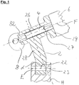
- the Sp Dr.iltician 8 is only partially cut with its housing 82 and otherwise shown very greatly simplified.
- the carrier unit Adjacent to the housing 82 of the expanding wedge unit 8, the carrier unit has a guide section 26, in which a guide element 4 along the guide axis F is arranged displaceably and guided.
- the guide section 26 in particular has a guide geometry 27, which is particularly preferably designed as a cylindrical cavity in the guide section 26 and secures the guide element 4 against displacement transversely to the guide axis F and facilitates sliding of the guide element 4.
- the carrier unit 2 has a second flange section 24 on which a brake cylinder 6 can be fixed or preferably fixed.
- the housing 82 of the expanding wedge unit 8, the guide section 26 and the second flange section 24 are preferably formed integrally with a holding section 28, wherein the holding section extends substantially along a holding axis H.
- the holding section 28 serves to position the upper part of the carrier unit 2 relative to a chassis of the commercial vehicle shown in the lower area of the image.
- the carrier unit preferably has a first flange section 22 which can be fixed indirectly and / or directly to the chassis of the commercial vehicle via a first engagement geometry 23. In the Fig.
- first engagement geometry 23 extends substantially along an engagement axis E, wherein the engagement axis E is advantageously aligned parallel to an axial direction of the commercial vehicle in order to fix the carrier unit 2 along this axial direction on the commercial vehicle.
- the cross section of the first engagement geometry 23 in the course along the engagement axis E is substantially constant, with smaller deviations, such as in the case of a thread, should be considered as substantially constant.
- the holding axis H is preferably pivoted at an angle ⁇ to the engagement axis E, whereby the upper area of the carrier unit 2 and in particular preferably the expanding wedge unit 8 are arranged offset in the figure to the left relative to the first flange portion 22.
- the arrangement of the brake shoes and the surrounding brake drum both not shown
- Due to the inclination of the support axis H relative to the engagement axis E of the arranged on the right side of the figure brake cylinder 6 is further pivoted to in the figure above and thus further spaced from the engagement axis E.
- the pivoting of the holding axis H relative to the engagement axis E thus ensures optimum placement of the carrier unit 2 within a brake system with respect to the adjacent components of the chassis.
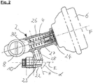
- Fig. 2 shows a further sectional view of a preferred embodiment of the carrier unit 2 according to the invention, wherein, in contrast to the in Fig. 1 shown Embodiment, the carrier unit 2 has two holding portions 28 which are each provided substantially parallel to each other between the guide portion 26 and the first flange portion 22 of the support unit.
- the carrier unit 2 is not partially solid, but is designed as a hollow body or web-like, the weight of the carrier unit 2 can be significantly reduced at the same time to be absorbed by the web-like holding portions 28 of the carrier unit 2 bending moments.
- the carrier unit 2 is not partially solid, but is designed as a hollow body or web-like, the weight of the carrier unit 2 can be significantly reduced at the same time to be absorbed by the web-like holding portions 28 of the carrier unit 2 bending moments.
- the first engagement portion 23 is designed as a threaded bore, in which a securing element 10 can be reached from the side of the carrier unit 2, on which the Sp Drkeiliser 8 is located.
- the securing element 10 then reachable, preferably in the left part of Fig. 2 arranged brake drum (not shown) was dismantled from the brake system.
- the second flange portion 24 has an extension parallel to the guide axis F of approximately up to 30 mm, particularly preferably 14-16 mm, wherein for the tested in the present invention ranges reaches the required strength and at the same time the weight fraction of the second Flange portion 24 could be kept low.
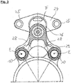
- Fig. 3 shows a sectional view of the already in Fig. 2 illustrated preferred embodiment of the carrier unit 2, wherein in Fig. 3 the sectional plane extends transversely to the engagement axis E.
- the carrier unit 2 not only along the engagement plane E has at least one, preferably two holding sections 28, but also transversely to the engagement direction E offset to each other preferably two holding sections 28 are provided.
- the carrier unit 2 has two first flange portions 22, which are spaced apart from each other and can be fixed to a respectively provided corresponding geometry of the chassis of the commercial vehicle.
- the cylindrical shape of the guide geometry 27 of the guide portion 26 can be seen, in which the guide element 4 is slidably disposed.
- the connection of the holding sections 28 to the guide portion 26 and the respective first flange portion 22 is characterized by rounded outer geometries, which allow a particularly favorable flow of force and avoid notch effects.
- the second flange portion 24 can be seen, which preferably has two spaced apart second engagement geometries, which are advantageously formed as through holes through which a corresponding bolt can be pushed through and in this way a brake cylinder with two attachment points on the second flange 24 can be fixed.
- the two second engagement geometries 25 are at a distance from one another which is at a ratio of 0.9-1.1, preferably 0.95-1.05, to the distance between the two first engagement geometries 23.
- the distance of the two second engagement geometries 25 is substantially equal to the distance of the first engagement geometries 23 to each other.
Description
Die vorliegende Erfindung betrifft eine Trägereinheit zum Einsatz in Bremssystemen von Kraftfahrzeugen, bevorzugt von Nutzfahrzeugen.The present invention relates to a carrier unit for use in brake systems of motor vehicles, preferably of commercial vehicles.
Trägereinheiten sind aus dem Stand der Technik insofern bekannt, als dass meist gegossene Bremsträger vorgesehen sind, an welchen die verschiedenen Baugruppen der Fahrzeugbremse festlegbar und über den Bremsträger mit beispielsweise der Achse verbunden sind. Die aus dem Stand der Technik bekannten Bremsträger weisen dabei im Allgemeinen den Nachteil auf, dass sie schwer gebaut sind und aufgrund einer Vielzahl von zu montierenden Bauteilen einen hohen Montageaufwand erfordern. Insbesondere im Bereich der Spreizkeiltrommelbremsen ist es bisher erforderlich, an einem Bremsträger eine Spreizkeileinheit durch Verschweißung oder Verschraubung festzulegen und weitere Adapterelemente für die Anbringung des Bremszylinders vorzusehen. Diese zusätzlichen Adapterelemente erhöhen zum einen den Bauraumbedarf und schaffen zum anderen auch eine Vielzahl anfälliger Verbindungsstellen, durch welche beispielsweise Schmutz und Flüssigkeiten in den Innenbereich der Spreizkeileinheit gelangen können. Es besteht daher ein signifikanter Verbesserungsbedarf hinsichtlich der Kompaktheit, der Fehleranfälligkeit, sowie der Montage eines Bremssystems.Carrier units are known from the prior art in that usually cast brake carrier are provided on which the various components of the vehicle brake can be fixed and connected via the brake carrier with, for example, the axis. The known from the prior art brake carrier in this case generally have the disadvantage that they are heavy-built and require a high installation cost due to a variety of components to be mounted. In particular, in the field of expanding wedge drum brakes, it has hitherto been necessary to fix an expanding wedge unit by welding or screwing on a brake carrier and to provide further adapter elements for the attachment of the brake cylinder. On the one hand, these additional adapter elements increase the space requirement and, on the other hand, also create a multiplicity of vulnerable connection points through which, for example, dirt and liquids can reach the interior region of the expanding wedge unit. There is therefore a significant need for improvement with regard to the compactness, the susceptibility to errors and the assembly of a brake system.
Die
Die
Aufgabe der vorliegenden Erfindung ist es, eine Trägereinheit bereitzustellen, welche sowohl die Montage des Bremssystems vereinfacht als auch Gewicht und Bauraum einspart sowie die Fehleranfälligkeit des Bremssystems verringert.Object of the present invention is to provide a carrier unit, which simplifies both the assembly of the brake system and saves weight and space and reduces the susceptibility of the brake system to failure.
Diese Aufgabe wird gelöst mit einer Trägereinheit gemäß Anspruch 1. Weitere Vorteile und Merkmale der vorliegenden Erfindung ergeben sich aus den abhängigen Ansprüchen.This object is achieved with a carrier unit according to claim 1. Further advantages and features of the present invention will become apparent from the dependent claims.
Erfindungsgemäß umfasst die Trägereinheit einen ersten Flanschabschnitt, einen zweiten Flanschabschnitt und einen Führungsabschnitt, wobei der erste Flanschabschnitt eine erste Eingriffsgeometrie zur Festlegung der Trägereinheit an einem Fahrwerk aufweist, wobei der zweite Flanschabschnitt eine zweite Eingriffsgeometrie zur Festlegung eines Bremszylinders aufweist, wobei der Führungsabschnitt benachbart zum zweiten Flanschabschnitt angeordnet ist und eine Führungsgeometrie zur Führung eines Führungselements entlang einer Führungsachse aufweist, wobei eine Spreizkeileinheit benachbart zum Führungsabschnitt vorgesehen ist und wobei die Spreizkeileinheit ein Gehäuse aufweist, das einstückig mit dem Führungsabschnitt ausgebildet ist. Ein wesentliches Merkmal der Trägereinheit ist, dass eine Spreizkeileinheit integral mit der Trägereinheit ausgebildet ist, wobei insbesondere das Gehäuse der Spreizkeileinheit einstückig mit dem entsprechend benachbarten Abschnitt der Trägereinheit ausgebildet ist. Benachbart zum Gehäuse der Trägereinheit ist dabei der Führungsabschnitt der Trägereinheit vorgesehen. Der Führungsabschnitt ist ein zumindest bereichsweise hohlkörperförmig ausgebildeter Abschnitt der Trägereinheit, in welchem ein Führungselement entlang einer Führungsachse verlagerbar angeordnet ist. Das Führungselement dient dabei insbesondere bevorzugt der Kraftübertragung einer Bremskraft, welche von einem an dem zweiten Flanschabschnitt angeflanschten Bremszylinder hin zu einer entsprechenden Spreizkeilmechanik, welche in der Spreizkeileinheit angeordnet ist, führt. Der Führungsabschnitt hat weiterhin die Funktion, sowohl die Geometrie der Spreizkeileinheit als auch das Führungselement sowie den Bremszylinder gegen das Eindringen von Schmutz, Fremdkörpern und Flüssigkeiten abzuschirmen. Indem das Gehäuse der Spreizkeileinheit einstückig mit dem Führungsabschnitt ausgebildet ist, kann vorteilhafterweise eine weitere Schnittstelle zwischen der Spreizkeileinheit und der Trägereinheit vermieden werden, durch welche im normalen Betrieb der Trägereinheit Schmutz und Flüssigkeiten gelangen könnten. Der erste Flanschabschnitt weist eine erste Eingriffsgeometrie zur Festlegung der Trägereinheit an einem Fahrwerk auf, wobei die erste Eingriffsgeometrie vorzugsweise eine standardisierte Eingriffsgeometrie ist, welche an Fahrwerken verschiedener Nutzfahrzeuge oder Nutzfahrzeugtypen standardmäßig in Eingriff bringbar ist. Insbesondere bevorzugt ist die zweite Eingriffsgeometrie des zweiten Flanschabschnitts ebenfalls eine standardisierte Schnittstelle zur Festlegung eines Bremszylinders, welche insbesondere durch vorzugsweise zwei Eingriffsgeometrien gekennzeichnet ist, die in einem bestimmten, standardisierten Abstand zueinander vorgesehen sind. Mit Vorteil kann die Trägereinheit daher in bereits vorhandene Bremssysteme integriert werden, wobei der zuvor verwendete Bremszylinder weiter angewendet werden kann.According to the invention, the carrier unit comprises a first flange portion, a second flange portion and a guide portion, wherein the first flange portion has a first engagement geometry for fixing the carrier unit to a chassis, wherein the second flange portion has a second engagement geometry for fixing a brake cylinder, wherein the guide portion adjacent to the second Flange portion is arranged and has a guide geometry for guiding a guide member along a guide axis, wherein a Spreizkeileinheit adjacent to the guide portion is provided and wherein the Spreizkeileinheit comprises a housing which is integrally formed with the guide portion. An essential feature of the support unit is that an expansion wedge unit is formed integrally with the support unit, wherein in particular the housing of the expansion wedge unit is formed integrally with the corresponding adjacent portion of the support unit. Adjacent to the housing of the carrier unit while the guide portion of the carrier unit is provided. The guide section is an at least partially hollow-body-shaped section of the carrier unit, in which a guide element is arranged to be displaceable along a guide axis. In this case, the guide element particularly preferably serves for the transmission of force of a braking force which leads from a brake cylinder flanged to the second flange section to a corresponding expanding wedge mechanism which is arranged in the expanding wedge unit. The guide section also has the function of both the geometry of the expanding wedge unit and the guide element and to shield the brake cylinder against the ingress of dirt, debris and liquids. By integrally forming the housing of the expanding wedge unit with the guide section, a further interface between the expanding wedge unit and the carrier unit can advantageously be avoided, through which dirt and liquids could pass during normal operation of the carrier unit. The first flange portion has a first engagement geometry for fixing the carrier unit to a running gear, wherein the first engagement geometry is preferably a standardized engagement geometry, which is engageable by default on trolleys of various commercial vehicles or commercial vehicle types. Particularly preferably, the second engagement geometry of the second flange portion is also a standardized interface for fixing a brake cylinder, which is characterized in particular by preferably two engagement geometries, which are provided at a certain, standardized distance from each other. Advantageously, the carrier unit can therefore be integrated into existing brake systems, wherein the previously used brake cylinder can be further applied.
In einer bevorzugten Ausführungsform ist der zweite Flanschabschnitt einstückig mit dem Führungsabschnitt ausgebildet. Mit anderen Worten ist der zweite Flanschabschnitt dabei vorzugsweise als einstückiges Gussteil gemeinsam mit dem Führungsabschnitt ausgebildet, wobei mit Vorteil eine nachträgliche Montage des zweiten Flanschabschnitts am Führungsabschnitt vermieden werden kann und gleichzeitig Wand- beziehungsweise Querschnittsgeometrien verwendet werden können, welche eine besonders gute Kraftübertragung bei gleichzeitig geringer Wandstärke erlauben. Durch die einstückige Ausbildung des zweiten Flanschabschnitts und des Führungsabschnitts kann dabei das Gewicht der Trägereinheit verringert und der Montageaufwand zum Anbringen eines Bremszylinders an der Trägereinheit deutlich verringert werden da ein Monteur nur ein Bauteil handhaben muss.In a preferred embodiment, the second flange portion is formed integrally with the guide portion. In other words, the second flange portion is preferably formed as a one-piece casting together with the guide portion, which advantageously a subsequent assembly of the second flange on the guide portion can be avoided while wall or cross-sectional geometries can be used, which is a particularly good power transmission at the same time Allow wall thickness. Due to the one-piece design of the second flange portion and the guide portion while the weight of the support unit can be reduced and the assembly costs for attaching a brake cylinder to the support unit can be significantly reduced because a fitter must handle only one component.
Mit Vorteil weist die Trägereinheit einen Halteabschnitt auf, welcher an den ersten Flanschabschnitt und den Führungsabschnitt grenzt und sich im Wesentlichen entlang einer Halteachse erstreckt, wobei der erste Flanschabschnitt, der Halteabschnitt und der Führungsabschnitt einstückig miteinander ausgebildet sind. Der Halteabschnitt dient vorzugsweise der Positionierung des Führungsabschnitts und damit auch des vorzugsweise einstückig mit dem Führungsabschnitt verbundenen ersten Flanschabschnitts sowie der vorzugsweise einstückig mit dem Führungsabschnitt verbundenen Spreizkeileinheit relativ zum Fahrwerk. Dabei weist der Halteabschnitt vorzugsweise eine Erstreckung längs einer Halteachse auf, wobei die Erstreckung des Halteabschnitts längs der Halteachse, beziehungsweise parallel zur Halteachse vorzugsweise seine größte Erstreckung ist. Mit Vorteil sind im Übergangsbereich zwischen dem Halteabschnitt und dem ersten Flanschabschnitt kraftflussoptimierte Außengeometrien des Halteabschnitts vorgesehen, das heißt vorzugsweise gerundete Außengeometrien, an denen mit Vorteil nur geringe Kerbwirkung bei Biegebeanspruchung des ersten Flanschabschnitts und des Halteabschnitts auftritt. Mittels solcher kraftflussoptimierter Geometrien können die erforderlichen Wandstärken verringert, das Gewicht reduziert und dennoch die benötigten Kräfte und Momente übertragen werden.Advantageously, the carrier unit has a holding section, which adjoins the first flange section and the guide section and extends substantially along a holding axis, wherein the first flange section, the holding section and the guide portion are formed integrally with each other. The holding section preferably serves to position the guide section and thus also the first flange section preferably integrally connected to the guide section and the expanding wedge unit preferably integrally connected to the guide section relative to the chassis. In this case, the holding portion preferably has an extension along a holding axis, wherein the extension of the holding portion along the holding axis, or parallel to the holding axis is preferably its largest extension. Advantageously, in the transition region between the holding section and the first flange section, force-optimized outer geometries of the holding section are provided, that is to say preferably rounded outer geometries on which advantageously only low notch effect occurs under bending stress of the first flange section and of the holding section. By means of such power flow optimized geometries, the required wall thicknesses can be reduced, the weight can be reduced and yet the required forces and moments can be transmitted.
In einer weiterhin bevorzugten Ausführungsform steht die Halteachse quer, vorzugsweise senkrecht zur Führungsachse. Mit der Anordnung des Halteabschnitts mit der daraus resultierenden Richtung, entlang derer die Halteachse verläuft, ist eine genaue Positionierung der Kraftübertragungsrichtung vom Bremszylinder zur Spreizkeileinheit definiert. Die senkrechte Ausrichtung des Halteabschnitts mit seiner Halteachse und des Führungsabschnitts mit der Führungsachse zueinander sorgt insbesondere bevorzugt für eine gleichmäßige Kraftübertragung bei Biegebeanspruchung, welche durch den relativ schweren Bremszylinder auf die Trägereinheit übertragen werden oder welche durch Schwingungen beispielsweise der Bremsbacken auf die Spreizkeileinheit übertragen werden.In a further preferred embodiment, the holding axis is transverse, preferably perpendicular to the guide axis. With the arrangement of the holding portion with the resulting direction along which the holding axis passes, an accurate positioning of the power transmission direction from the brake cylinder is defined for Spreizkeileinheit. The vertical alignment of the holding portion with its holding axis and the guide portion with the guide axis to each other particularly preferably provides for a uniform force transmission under bending stress, which are transmitted by the relatively heavy brake cylinder on the carrier unit or which are transmitted by vibrations, for example, the brake shoes on the Spreizkeileinheit.
Mit Vorteil erstreckt sich die erste Eingriffsgeometrie im Wesentlichen längs einer Eingriffsachse, wobei die Halteachse um einen Winkel zur Eingriffsachse verschwenkt ist und wobei der Winkel kleiner 90° ist. Weiterhin bevorzugt ist es, dass die Eingriffsachse, entlang derer sich die Eingriffsgeometrie erstreckt beziehungsweise entlang derer die Eingriffsgeometrie vorteilhafterweise in Eingriff mit dem Fahrwerk eines Nutzfahrzeuges gebracht werden kann, im Wesentlichen parallel zu einer Axialrichtung des Fahrwerkes, beispielsweise parallel zu der Rotationsrichtung der Fahrzeugräder angeordnet ist. Der Begriff "im Wesentlichen" bedeutet im Rahmen der vorliegenden Erfindung, dass kleinere Abweichungen, beispielsweise verursacht durch Fertigungstoleranzen im Rahmen der vorliegenden Erfindung als parallel gewertet werden. Mit Vorteil ist die Trägereinheit längs der Eingriffsachse, welche mit Vorteil parallel zur Axialrichtung verläuft, an dem Fahrwerk des Nutzfahrzeuges festgelegt, wobei insbesondere bevorzugt eine gute Erreichbarkeit der entsprechenden Befestigungsmittel längs der Eingriffsachse gegeben ist. Weiterhin bevorzugt ist die Halteachse um einen Winkel zur Eingriffsachse verschwenkt, wobei dieser Winkel kleiner als 90° ist. Besonders bevorzugt wird der Winkel dabei auf der Seite der Trägereinheit gemessen, auf der sich die Spreizkeileinheit befindet. Durch eine Anordnung der Halteachse schräg relativ zur Eingriffsachse ist es möglich, den oberen Teil der Trägereinheit, das heißt den aus Spreizkeileinheit, Führungsabschnitt und zweitem Flanschabschnitt bestehenden Bereich in das Innere einer Bremstrommel hineinragen zu lassen, um dort die Spreizkeileinheit in Eingriff mit den jeweils vorgesehenen Bremsbacken bringen zu können. Außerdem wird durch die schräge Anordnung der Halteachse auch der Bremszylinder in ausreichender Entfernung zur Achse des Nutzfahrzeuges angeordnet, sodass bei Schwingungen im Fahrwerksystem keine Beschädigung durch Schwingungen und auftretendem Kontakt zwischen dem Bremszylinder und angrenzenden Geometrien des Fahrwerks auftreten. Für den Fall, dass sich im dreidimensionalen Raum die Eingriffsachse und die Halteachse nicht schneiden, so ist es bevorzugt, dass der Winkel zwischen Eingriffsachse und Halteachse als Winkel zwischen den Projektionen der Eingriffsachse und der Halteachse auf eine, vorzugsweise durch den Führungsabschnitt verlaufende Schnittebene bestimmt ist.Advantageously, the first engagement geometry extends substantially along an engagement axis, wherein the support axis is pivoted at an angle to the engagement axis and wherein the angle is smaller than 90 °. It is further preferred that the engagement axis, along which the engagement geometry extends or along which the engagement geometry can be advantageously brought into engagement with the chassis of a commercial vehicle, substantially parallel is arranged to an axial direction of the chassis, for example, parallel to the direction of rotation of the vehicle wheels. The term "essentially" in the context of the present invention means that smaller deviations, for example caused by manufacturing tolerances, are considered parallel in the context of the present invention. Advantageously, the carrier unit along the engagement axis, which extends parallel to the axial direction with advantage, fixed to the chassis of the commercial vehicle, in particular preferably a good accessibility of the corresponding fastening means along the engagement axis is given. Further preferably, the holding axis is pivoted at an angle to the engagement axis, said angle being less than 90 °. Particularly preferably, the angle is measured on the side of the carrier unit on which the expanding wedge unit is located. By arranging the holding axis obliquely relative to the engagement axis, it is possible to allow the upper part of the carrier unit, that is to say the area consisting of expanding wedge unit, guide section and second flange section, to protrude into the interior of a brake drum, in order to engage the expanding wedge unit in each case To be able to bring brake shoes. In addition, the brake cylinder is arranged at a sufficient distance from the axis of the commercial vehicle by the oblique arrangement of the holding axis, so that no vibrations due to vibrations and occurring contact between the brake cylinder and adjacent geometries of the chassis occur in vibrations in the suspension system. In the event that the engagement axis and the support axis do not intersect in the three-dimensional space, it is preferred that the angle between the engagement axis and the support axis is determined as an angle between the projections of the engagement axis and the support axis on a, preferably through the guide portion extending cutting plane ,
In einer bevorzugten Ausführungsform liegt der Winkel im Bereich von 45° bis 89°, vorzugsweise im Bereich von 60° bis 85° und besonders bevorzugt bei etwa 70° bis 85°. Der relativ weit gewählte Bereich von 45° bis 89° ist dabei bevorzugt für Trägereinheiten, welche zum Festlegen besonders vieler verschiedener Bremszylinder ausgelegt sind. Es hat sich gezeigt, dass in diesem Bereich von 45° bis 89° alle derzeit auf dem Markt vorhandenen Bremszylinder ohne Weiteres in ein Bremssystem mit einer erfindungsgemäßen Trägereinheit integriert werden können, ohne dass Beschädigungen durch Anschlagen an benachbarte Fahrwerksgeometrien befürchtet werden müssen. Der besonders bevorzugte Bereich von 60° bis 85° hat sich als vorteilhaft erwiesen, da auf diese Weise eine besonders kompakte Bauweise der Trägereinheit erreicht wird, wobei einerseits ein ausreichender Abstand eines an dem zweiten Flanschabschnitt festgelegten Bremszylinders von den benachbarten Fahrwerksgeometrien gewährleistet ist und andererseits die Erstreckung des Halteabschnitts relativ gering gewählt werden kann und auf diese Weise Gewicht einsparbar ist. Der insbesondere bevorzugte Bereich von 70° bis 85° hat sich als vorteilhaft zum Einsatz mit Spreizkeilbremseinheiten herausgestellt, da hier eine optimale Anordnung des oberen Bereiches der Trägereinheit relativ zur ersten Eingriffsgeometrie beziehungsweise relativ zum ersten Flanschabschnitt erreichbar ist, um einerseits unter Gewichtseinsparung, andererseits mit einer möglichst einfachen Montage eine Trägereinheit in das Bremssystem eines Nutzfahrzeuges zu integrieren.In a preferred embodiment, the angle is in the range of 45 ° to 89 °, preferably in the range of 60 ° to 85 ° and more preferably about 70 ° to 85 °. The relatively wide range of 45 ° to 89 ° is preferred for carrier units, which are designed to set especially many different brake cylinder. It has been found that in this range from 45 ° to 89 ° all present on the market brake cylinder can be readily integrated into a brake system with a carrier unit according to the invention, without having to fear damage by striking adjacent chassis geometries. The particularly preferred range of 60 ° to 85 ° has proven to be advantageous, since in this way a particularly compact design of the carrier unit is achieved, on the one hand, a sufficient distance of a fixed to the second flange brake cylinder is ensured by the adjacent chassis geometries and on the other hand Extension of the holding section can be chosen relatively small and in this way weight can be saved. The particularly preferred range of 70 ° to 85 ° has proven to be advantageous for use with Spreizkeilbremseinheiten, since an optimal arrangement of the upper portion of the support unit relative to the first engagement geometry or relative to the first flange is reached, on the one hand with weight savings, on the other hand with a as simple as possible to integrate a carrier unit in the braking system of a commercial vehicle.
Mit Vorteil ist die erste Eingriffsgeometrie mittelbar und/oder unmittelbar in formschlüssigem Eingriff mit einem korrespondierenden Abschnitt des Fahrwerks bringbar. Ein mittelbarer formschlüssiger Eingriff wird dabei besonders bevorzugt durch einen Bolzen oder eine Schraubverbindung hergestellt. Ein unmittelbarer formschlüssiger Eingriff kann dabei vorzugsweise durch einen Vorsprung am ersten Flanschabschnitt beziehungsweise der ersten Eingriffsgeometrie hergestellt sein, welche in eine entsprechende Rücksprungsgeometrie an dem korrespondierenden Abschnitt des Fahrwerks formschlüssig eingreift, um beispielsweise die Trägereinheit relativ zum Fahrwerk gegen Verdrehung um die Eingriffsachse zu sichern. Eine formschlüssige Anbindung der Trägereinheit an das Fahrwerk ist bevorzugt, um erstens eine Demontierbarkeit der Trägereinheit vom Fahrwerk zu gewährleisten und andererseits die bei einer bis dato üblichen Schweißverbindung des Bremsträgers an der Fahrwerksachse auftretenden Thermospannungen und Gefügebeschädigungen vermeiden zu können.Advantageously, the first engagement geometry can be brought indirectly and / or directly into positive engagement with a corresponding section of the chassis. An indirect positive engagement is particularly preferably produced by a bolt or a screw connection. A direct form-fitting engagement can preferably be made by a projection on the first flange portion or the first engagement geometry, which engages positively in a corresponding recess geometry on the corresponding portion of the chassis to secure, for example, the carrier unit relative to the chassis against rotation about the engagement axis. A positive connection of the carrier unit to the chassis is preferred to firstly to ensure disassembly of the carrier unit from the chassis and on the other hand to avoid the occurring at a usual welding joint of the brake carrier to the suspension axle thermal stresses and structural damage.
Mit Vorteil ist ein Sicherungselement vorgesehen, welches entlang der Eingriffsachse in formschlüssigen Eingriff mit der ersten Eingriffsgeometrie bringbar ist, wobei das Sicherungselement von der Seite der Trägereinheit zugänglich ist, auf der sich die Spreizkeileinheit befindet. Das Sicherungselement ist vorzugsweise eine Schraube oder ein Gewindebolzen und ist mit Vorteil von der Seite der Trägereinheit zugänglich, auf welcher sich die Spreizkeileinheit befindet. Mit anderen Worten ist das Sicherungselement vorzugsweise von der Außenseite des Fahrwerks zugänglich, das heißt, nachdem das Rad und die Bremstrommel der Bremseinheit vom Fahrwerk demontiert wurden, kann die Trägereinheit durch Lösen des Sicherungselements von außen in einfacher Weise demontiert werden. In einer alternativ bevorzugten Ausführungsform kann das Sicherungselement auch als Mutter ausgebildet sein, welche mit einer beispielsweise als Gewindestab ausgebildeten ersten Eingriffsgeometrie in Eingriff bringbar ist.Advantageously, a securing element is provided, which can be brought along the engagement axis in positive engagement with the first engagement geometry, the securing element being accessible from the side of the carrier unit the spreading wedge unit is located. The securing element is preferably a screw or a threaded bolt and is advantageously accessible from the side of the carrier unit on which the expanding wedge unit is located. In other words, the securing element is preferably accessible from the outside of the chassis, that is, after the wheel and the brake drum of the brake unit have been removed from the chassis, the carrier unit can be removed by loosening the securing element from the outside in a simple manner. In an alternative preferred embodiment, the securing element may also be designed as a nut, which can be brought into engagement with a first engagement geometry designed, for example, as a threaded rod.
Alternativ bevorzugt kann das Sicherungselement von der Seite der Trägereinheit zugänglich sein, auf welcher sich der zweite Flanschabschnitt befindet. Insbesondere, wenn es bevorzugt ist, dass die Trägereinheit auch ohne vorherige Demontage des Rades, beziehungsweise der Bremstrommel des Bremssystems, von diesem demontiert oder an ein solches anmontiert werden kann, ist es bevorzugt, das Sicherungselement an der Seite der Trägereinheit anzuordnen, an der sich der zweite Flanschabschnitt befindet. Mit anderen Worten ist das Sicherungselement also vorzugsweise von der Innenseite des Fahrwerks aus erreichbar, wobei der erste Flanschabschnitt und die erste Eingriffsgeometrie vorteilhafterweise derart von dem Achskörper und anderen Baugruppen des Fahrwerks entfernt angeordnet sind, dass genügend Platz für den Einsatz eines Momentschlüssels oder eines druckluftbetriebenen Schraubgeräts vorhanden ist.Alternatively preferably, the securing element can be accessible from the side of the carrier unit on which the second flange section is located. In particular, if it is preferred that the carrier unit can also be disassembled or attached to such without prior disassembly of the wheel, or the brake drum of the brake system, it is preferable to arrange the securing element on the side of the carrier unit on which the second flange portion is located. In other words, the securing element is thus preferably accessible from the inside of the chassis, wherein the first flange portion and the first engagement geometry are advantageously arranged away from the axle body and other components of the chassis that sufficient space for the use of a torque wrench or a pneumatic screwdriver is available.
Besonders bevorzugt ist die erste Eingriffsgeometrie als Gewindebohrung ausgebildet. Mit dieser bevorzugten Ausführungsform wird die Montage der Trägereinheit am Fahrwerk eines Nutzfahrzeuges vereinfacht, da lediglich eine Schraube mit einer Eingriffsgeometrie in Eingriff gebracht werden muss, um die Trägereinheit am Fahrwerk festzulegen. Insbesondere entfallen zusätzlich vorgesehene Muttern oder andere Fixierelemente. Mit Vorteil ist als Gewindeart für die erste Eingriffsgeometrie ein selbstsicherndes ISO-Gewinde vorgesehen.Particularly preferably, the first engagement geometry is formed as a threaded bore. With this preferred embodiment, the mounting of the carrier unit on the chassis of a utility vehicle is simplified, since only one screw with an engagement geometry must be brought into engagement to set the carrier unit on the chassis. In particular, additional provided for nuts or other fixing elements. Advantageously, a self-locking ISO thread is provided as the thread type for the first engagement geometry.
Alternativ bevorzugt ist die erste Eingriffsgeometrie als Gewindebolzen ausgebildet und vorzugsweise einstückig mit dem ersten Flanschabschnitt ausgeführt. Auch mit dieser alternativ vorgesehenen Ausführungsform der ersten Eingriffsgeometrie kann die benötigte Anzahl der für die Montage der Trägereinheit erforderlichen Einzelteile verringert werden und somit nicht nur Gewicht, sondern auch Montagezeit eingespart werden.Alternatively preferably, the first engagement geometry is formed as a threaded bolt and preferably designed in one piece with the first flange portion. Also with this alternative embodiment of the first engagement geometry, the required number of required for the assembly of the carrier unit items can be reduced and thus not only weight, but also assembly time can be saved.
In einer besonders bevorzugten Ausführungsform weist der erste Flanschabschnitt zwei Eingriffsgeometrien auf, welche voneinander beabstandet angeordnet sind, wobei die Eingriffsachsen der jeweiligen Eingriffsgeometrien parallel zueinander verlaufen. Insbesondere, um eine Verschwenkung der Trägereinheit um eine mit Vorteil parallel zu der Eingriffsachse verlaufenden Axialrichtung des Fahrwerkes zu verhindern, sind zumindest zwei erste Eingriffsgeometrien vorgesehen. Um den Montageaufwand gering zu halten, ist es weiterhin bevorzugt, nicht mehr als vier erste Eingriffsgeometrien am ersten Flanschabschnitt vorzusehen, welche jeweils einzeln mit dem Fahrwerk des Nutzfahrzeuges in Eingriff bringbar sind. Dabei ist der Abstand der Eingriffsgeometrien voneinander vorzugsweise kleiner als die Erstreckung des Halteabschnitts längs der Halteachse. Durch diese bevorzugte Dimensionierung des Abstandes der ersten Eingriffsgeometrien relativ zur Erstreckung des einen oder der zumindest zwei vorgesehenen Halteabschnitte ist ein günstiger Kompromiss zwischen dem durch das zusätzliche Material anfallenden Gewicht und einer gleichzeitig ausreichend hohen Sicherung der Trägereinheit gegen Verdrehung relativ zum Fahrwerk gegeben.In a particularly preferred embodiment, the first flange portion on two engagement geometries, which are spaced from each other, wherein the engagement axes of the respective engagement geometries are parallel to each other. In particular, in order to prevent a pivoting of the carrier unit about an axial direction of the running gear, which is advantageously parallel to the engagement axis, at least two first engagement geometries are provided. In order to keep assembly costs low, it is further preferred to provide not more than four first engagement geometries on the first flange portion, which are individually engageable with the chassis of the commercial vehicle in engagement. In this case, the distance of the engagement geometries from each other is preferably smaller than the extension of the holding portion along the support axis. By this preferred dimensioning of the distance of the first engagement geometries relative to the extension of the one or at least two holding sections provided a favorable compromise between the resulting by the additional material weight and a simultaneously sufficiently high security of the carrier unit against rotation relative to the chassis is given.
Mit Vorteil sind zwei Halteabschnitte vorgesehen, welche durch einen Freiraum voneinander getrennt sind, wobei die mittlere Querschnittsfläche der Halteabschnitte in einem Verhältnis von 0,2 bis 1,3, vorzugsweise von 0,3 bis 0,9 und besonders bevorzugt von ca. 0,5 bis 0,8 zur mittleren Querschnittsfläche des Freiraums steht. Als mittlere Querschnittsfläche der Halteabschnitte wird dabei bevorzugt die Summe der Querschnittsflächen der einzelnen Halteabschnitte in einem Querschnitt durch die Trägereinheit gewählt, in welchem die durchschnittliche Querschnittsdicke beziehungsweise -breite des Halteabschnitts im Verlauf längs der Eingriffsachse der benachbart zum Halteabschnitt befindlichen Eingriffsgeometrie vorliegt. Die Querschnittsfläche des Freiraumes wird vorzugsweise in derselben Schnittebene durch die Trägereinheit wie die Querschnittsfläche der Halteabschnitte bestimmt. Das Verhältnis der beiden Querschnittsflächen zueinander ist dabei ein Ausdruck dafür, wie "massiv" die Halteabschnitte ausgeführt sind. Je kleiner das Verhältnis der Querschnittsfläche der Halteabschnitte relativ zum Querschnitt des Freiraumes ist, desto dünnwandiger beziehungsweise schmaler sind die Halteabschnitte ausgeführt, wobei das Gewicht deutlich reduziert ist. Insbesondere, wenn die Trägereinheit eine relativ kompakte Bauweise aufweisen soll, wenig Bauraum beanspruchen und einen geringen Abstand der Halteabschnitte voneinander aufweisen soll, ist der Freiraum im Vergleich zu den Halteabschnitten relativ klein, sodass das Verhältnis bis zu 1,3 ansteigen kann. Als günstiger Kompromiss zwischen einer leichtgewichtigen Bauweise und einer andererseits ausreichend hohen Festigkeit der Halteabschnitte der Trägereinheit hat sich ein Bereich von ca. 0,5 bis 0,8 herausgestellt, wobei in diesem Verhältnisbereich die besten Ergebnisse im Rahmen der vorliegenden Erfindung erzielt werden konnten.Advantageously, two holding sections are provided, which are separated from one another by a free space, wherein the average cross-sectional area of the holding sections in a ratio of 0.2 to 1.3, preferably from 0.3 to 0.9 and particularly preferably from about 0, 5 to 0.8 to the average cross-sectional area of the free space. In this case, the sum of the cross-sectional areas of the individual holding sections in a cross-section through the carrier unit is preferably selected as the average cross-sectional area of the holding sections, in which the average cross-sectional thickness or width of the holding section extends along the engagement axis of the engagement geometry adjacent to the holding section is present. The cross-sectional area of the clearance is preferably determined in the same sectional plane by the carrier unit as the cross-sectional area of the holding portions. The ratio of the two cross-sectional areas to each other is an expression of how "solid" the holding sections are executed. The smaller the ratio of the cross-sectional area of the holding sections relative to the cross-section of the free space, the thinner-walled or narrower the holding sections are executed, wherein the weight is significantly reduced. In particular, if the carrier unit should have a relatively compact design, take up little space and should have a small distance of the holding sections from each other, the free space compared to the holding sections is relatively small, so that the ratio can increase up to 1.3. As a favorable compromise between a lightweight construction and on the other hand sufficiently high strength of the holding portions of the carrier unit, a range of about 0.5 to 0.8 has been found, and in this ratio range, the best results could be achieved in the context of the present invention.
In einer besonders bevorzugten Ausführungsform ist das Gehäuse der Spreizkeileinheit aus Sphäroguss hergestellt. Die Ausbildung aus Sphäroguss erlaubt dabei zum einen eine präzise Ausgestaltung der entsprechenden Außen- beziehungsweise Innengeometrien der Spreizkeileinheit und zum anderen eine günstige Anbindung durch beispielsweise Angießen des Gehäuses der Spreizkeileinheit an den entsprechenden Führungsabschnitt der Trägereinheit, welches aus einem günstigeren, vergleichsweise weniger festen Material hergestellt sein kann als Sphäroguss. Insbesondere bevorzugt ist dabei die gesamte Trägereinheit gemeinsam mit dem Gehäuse der Spreizkeileinheit als ein Sphärogussbauteil ausgeführt.In a particularly preferred embodiment, the housing of the expanding wedge unit is made of nodular cast iron. The formation of nodular cast iron allows on the one hand a precise configuration of the corresponding outer or inner geometries of the expanding wedge unit and on the other a favorable connection by, for example, casting the housing of the expanding wedge unit to the corresponding guide section of the support unit, which are made of a cheaper, relatively less solid material can be used as ductile iron. Particularly preferably, the entire carrier unit is designed together with the housing of the expanding wedge unit as a spheroidal cast iron component.
Mit Vorteil weist die Trägereinheit nicht mehr als vier erste Eingriffsgeometrien, vorzugsweise nicht mehr als zwei erste Eingriffsgeometrien auf. Durch die bevorzugte Reduzierung der Anzahl erster Eingriffsgeometrien wird der Montageaufwand verringert. Gleichzeitig hat es sich aber gezeigt, dass bei erhöhtem Festigkeitsbedarf drei bis vier erste Eingriffsgeometrien gerechtfertigt sind, obwohl der Montageaufwand steigt.Advantageously, the carrier unit has no more than four first engagement geometries, preferably no more than two first engagement geometries. The preferred reduction of the number of first engagement geometries reduces the assembly effort. At the same time, however, it has been shown that with increased strength requirement three to four first engagement geometries are justified, although the assembly costs increase.
Weitere Vorteile und Merkmale der vorliegenden Erfindung ergeben sich aus der nachfolgenden Beschreibung mit Bezug auf die beigefügten Figuren. Es versteht sich, dass einzelne, in den jeweiligen Ausführungsformen beschriebene Merkmale auch in anderen Ausführungsformen Anwendung finden können, sofern dies nicht explizit ausgeschlossen ist oder sich aus technischen Gründen verbietet. Es zeigen:
- Fig. 1
- eine schematische Schnittansicht einer ersten bevorzugten Ausführungsform der erfindungsgemäßen Trägereinheit,
- Fig. 2
- eine zweite Schnittansicht einer bevorzugten Ausführungsform der erfindungsgemäßen Trägereinheit, und
- Fig. 3
- eine teilweise geschnittene Ansicht einer bevorzugten Ausführungsform der erfindungsgemäßen Trägereinheit.
- Fig. 1
- a schematic sectional view of a first preferred embodiment of the carrier unit according to the invention,
- Fig. 2
- a second sectional view of a preferred embodiment of the carrier unit according to the invention, and
- Fig. 3
- a partially sectioned view of a preferred embodiment of the carrier unit according to the invention.
Bei der in
- 2 - Trägereinheit2 - carrier unit
- 4 - Führungselement4 - guide element
- 6 - Bremszylinder6 - brake cylinder
- 8 - Spreizkeileinheit8 - spreading wedge unit
- 10 - Sicherungselement10 - securing element
- 22 - erster Flanschabschnitt22 - first flange section
- 23 - erste Eingriffsgeometrie23 - first engagement geometry
- 24 - zweiter Flanschabschnitt24 - second flange section
- 25 - zweite Eingriffsgeometrie25 - second engagement geometry
- 26 - Führungsabschnitt26 - guide section
- 27 - Führungsgeometrie27 - Guide geometry
- 28 - Halteabschnitt28 - holding section
- 29 - Freiraum29 - free space
- 82 - Gehäuse82 - housing
- α - Winkelα - angle
- E - EingriffsachseE - engagement axis
- F - FührungsachseF - Guide axle
- H - HalteabschnittH - holding section
Claims (10)
- A support unit (2) comprising a first flange portion (22), a second flange portion (24) and a guiding portion (26),
wherein the first flange portion (22) has a first engagement geometry (23) for securing the support unit (2) to a chassis,
wherein the second flange portion (24) has a second engagement geometry (25) for securing a brake cylinder (6),
wherein the guiding portion (26) is arranged adjacent to the second flange portion (24) and has a guiding geometry (27) for guiding a guiding element (4) along a guiding axis (F),
wherein an expansion wedge unit (8) is provided adjacent to the guiding portion (26) and
characterized in that the expansion wedge unit (8) has a housing (82) which is constructed one pieced with the guiding portion (26). - The support unit (2) as claimed in claim 1,
wherein the second flange portion (24) is constructed one pieced with the guiding portion (26). - The support unit (2) as claimed in either claim 1 or claim 2,
having a retention portion (28) which adjoins the first flange portion (22) and the guiding portion (26) and which extends substantially along a retention axis (H),
wherein the first flange portion (22), the retention portion (28) and the guiding portion (24) are constructed one pieced with each other. - The support unit (2) as claimed in claim 3,
wherein the retention axis (H) is located transversely relative to the guiding axis (F). - The support unit (2) as claimed in claim 3 or claim 4,
wherein the first engagement geometry (23) extends substantially along an engagement axis (E),
wherein the retention axis (H) is pivoted through an angle (α) with respect to the engagement axis (E), wherein the angle (α) is smaller than 90°. - The support unit (2) as claimed in claim 5,
wherein the angle (α) is in the range from 45° to 89°, preferably in the range from 60° to 85° and in a particularly preferred manner approximately from 70° to 85°. - The support unit as claimed in one of the preceding claims,
wherein there is provided a securing element (10) which can be moved along the engagement axis (E) into positive-locking engagement with the first engagement geometry,
wherein the securing element (10) is accessible from the side of the support unit (2) at which the expansion wedge unit (8) is located. - The support unit (2) as claimed in one of the preceding claims,
wherein the first flange portion (22) has two engagement geometries (23) which are arranged spaced apart from each other,
wherein the engagement axes (E) of the engagement geometries (23) extend parallel with each other. - The support unit (2) as claimed in claim 8,
wherein there are provided two retention portions (28) which are separated from each other by means of a free space (29),
wherein the mean cross-sectional surface-area of the retention portions (28) is at a ratio of from 0.2 to 1.3, preferably from 0.3 to 0.9 and in a particularly preferred manner from approximately 0.5 to 0.8 with respect to the mean cross-sectional surface-area of the free space (29). - The support unit (2) as claimed in one of the preceding claims,
having no more than four first engagement geometries (23), preferably no more than two first engagement geometries (23).
Priority Applications (1)
| Application Number | Priority Date | Filing Date | Title |
|---|---|---|---|
| PL15723909T PL3146228T3 (en) | 2014-05-20 | 2015-05-18 | Brake support |
Applications Claiming Priority (2)
| Application Number | Priority Date | Filing Date | Title |
|---|---|---|---|
| DE102014209502.6A DE102014209502B4 (en) | 2014-05-20 | 2014-05-20 | Carrier unit |
| PCT/EP2015/060850 WO2015177073A1 (en) | 2014-05-20 | 2015-05-18 | Support unit |
Publications (3)
| Publication Number | Publication Date |
|---|---|
| EP3146228A1 EP3146228A1 (en) | 2017-03-29 |
| EP3146228B1 true EP3146228B1 (en) | 2017-09-13 |
| EP3146228B2 EP3146228B2 (en) | 2024-01-17 |
Family
ID=53199977
Family Applications (1)
| Application Number | Title | Priority Date | Filing Date |
|---|---|---|---|
| EP15723909.6A Active EP3146228B2 (en) | 2014-05-20 | 2015-05-18 | Brake support |
Country Status (10)
| Country | Link |
|---|---|
| US (1) | US10232837B2 (en) |
| EP (1) | EP3146228B2 (en) |
| CN (1) | CN106460972B (en) |
| AU (1) | AU2015263261B2 (en) |
| CA (1) | CA2949578C (en) |
| DE (1) | DE102014209502B4 (en) |
| MX (1) | MX2016015224A (en) |
| PL (1) | PL3146228T3 (en) |
| RU (1) | RU2651450C1 (en) |
| WO (1) | WO2015177073A1 (en) |
Citations (5)
| Publication number | Priority date | Publication date | Assignee | Title |
|---|---|---|---|---|
| US3322241A (en) | 1966-01-24 | 1967-05-30 | Rockwell Standard Co | Brake system |
| DE2550855A1 (en) | 1974-11-15 | 1976-05-20 | Girling Ltd | ACTUATING DEVICE FOR VEHICLE BRAKES |
| US4621713A (en) | 1984-02-29 | 1986-11-11 | Societe Anonyme D.B.A. | Actuating mechanism for a disc brake |
| DE102011088847A1 (en) | 2011-12-16 | 2013-06-20 | Saf-Holland Gmbh | Brake system of a drum brake |
| WO2013087737A1 (en) | 2011-12-16 | 2013-06-20 | Saf-Holland Gmbh | Brake carrier |
Family Cites Families (24)
| Publication number | Priority date | Publication date | Assignee | Title |
|---|---|---|---|---|
| US3136227A (en) * | 1960-08-29 | 1964-06-09 | Rockwell Standard Co | Brake operating mechanism |
| US3269492A (en) * | 1963-06-06 | 1966-08-30 | Rockwell Standard Co | Guide and centering means for a brake actuating rod |
| GB1152938A (en) | 1967-03-02 | 1969-05-21 | Teves Gmbh Alfred | Improvements in or relating to Disc Brakes |
| US3599763A (en) * | 1970-01-26 | 1971-08-17 | Bendix Corp | Anchor piston for wedge brake |
| GB1418630A (en) | 1971-12-16 | 1975-12-24 | Automotive Prod Co Ltd | Internal shoe drum brakes and to fluid pressure braking systems including such brakes |
| GB2015098B (en) * | 1978-02-22 | 1982-04-28 | Girling Ltd | Drum brakes for vehicles |
| US4369863A (en) * | 1979-08-31 | 1983-01-25 | Lucas Industries Limited | Internal shoe drum brakes for vehicles |
| AU545708B2 (en) * | 1980-12-09 | 1985-07-25 | Automotive Products Ltd. | Hydraulic wheel cylinder assemblies |
| US4519482A (en) * | 1982-02-05 | 1985-05-28 | Allied Corporation | Wedge actuated drum brake assembly |
| US4445597A (en) * | 1982-06-17 | 1984-05-01 | Eaton Corporation | Spider assembly for drum brake |
| FR2590219B1 (en) * | 1985-11-20 | 1991-02-01 | Bendix France | ELECTRIC BRAKING DEVICE FOR VEHICLE |
| GB8927638D0 (en) * | 1989-12-07 | 1990-02-07 | Rubery Owen Rockwell Ltd | Brake assemblies |
| CA2030315A1 (en) * | 1990-06-26 | 1991-12-27 | Sung J. Cho | Brake spider assembly |
| US5613577A (en) * | 1994-12-09 | 1997-03-25 | Ford Motor Company | Automotive disc brake with improved caliper assembly |
| US6247560B1 (en) | 1996-12-12 | 2001-06-19 | Federal-Mogul Technology Limited | Slidable brake disc system |
| JP2001107999A (en) * | 1999-10-07 | 2001-04-17 | Nisshinbo Ind Inc | Drum brake device |
| RU2340484C1 (en) | 2007-06-19 | 2008-12-10 | Открытое акционерное общество "РИТМ" ТПТА | Tee for brake conduit of rolling equipment |
| US20100193303A1 (en) | 2009-02-05 | 2010-08-05 | Bendix Spicer Foundation Brake Llc | Brake spider weldment and anchor pin assembly |
| DE102011088848B4 (en) * | 2011-12-16 | 2015-05-13 | Saf-Holland Gmbh | Braking system for commercial vehicles |
| SE537115C2 (en) * | 2012-07-05 | 2015-01-20 | Scania Cv Ab | Bearing bracket configuration for drum brake and method for mounting a bearing bracket configuration |
| AU2014287087A1 (en) * | 2013-07-12 | 2015-11-05 | Hendrickson Usa, L.L.C. | Axle brake bracket for thin-wall axle |
| US9677628B2 (en) * | 2013-09-16 | 2017-06-13 | Arvinmeritor Technology, Llc | Drum brake assembly and method of manufacture |
| GB2524876A (en) * | 2014-02-14 | 2015-10-07 | Tse Brakes Inc | Pivoting air chamber for braking system |
| US9574626B1 (en) * | 2015-07-28 | 2017-02-21 | Bendix Spicer Foundation Brake Llc | Rigid bracket assembly for mounting a brake assembly and brake actuator |
-
2014
- 2014-05-20 DE DE102014209502.6A patent/DE102014209502B4/en not_active Expired - Fee Related
-
2015
- 2015-05-18 EP EP15723909.6A patent/EP3146228B2/en active Active
- 2015-05-18 MX MX2016015224A patent/MX2016015224A/en active IP Right Grant
- 2015-05-18 CA CA2949578A patent/CA2949578C/en not_active Expired - Fee Related
- 2015-05-18 US US15/312,112 patent/US10232837B2/en not_active Expired - Fee Related
- 2015-05-18 RU RU2016148464A patent/RU2651450C1/en not_active IP Right Cessation
- 2015-05-18 AU AU2015263261A patent/AU2015263261B2/en not_active Ceased
- 2015-05-18 WO PCT/EP2015/060850 patent/WO2015177073A1/en active Application Filing
- 2015-05-18 CN CN201580027272.3A patent/CN106460972B/en not_active Expired - Fee Related
- 2015-05-18 PL PL15723909T patent/PL3146228T3/en unknown
Patent Citations (5)
| Publication number | Priority date | Publication date | Assignee | Title |
|---|---|---|---|---|
| US3322241A (en) | 1966-01-24 | 1967-05-30 | Rockwell Standard Co | Brake system |
| DE2550855A1 (en) | 1974-11-15 | 1976-05-20 | Girling Ltd | ACTUATING DEVICE FOR VEHICLE BRAKES |
| US4621713A (en) | 1984-02-29 | 1986-11-11 | Societe Anonyme D.B.A. | Actuating mechanism for a disc brake |
| DE102011088847A1 (en) | 2011-12-16 | 2013-06-20 | Saf-Holland Gmbh | Brake system of a drum brake |
| WO2013087737A1 (en) | 2011-12-16 | 2013-06-20 | Saf-Holland Gmbh | Brake carrier |
Also Published As
| Publication number | Publication date |
|---|---|
| DE102014209502B4 (en) | 2020-12-10 |
| US10232837B2 (en) | 2019-03-19 |
| CN106460972B (en) | 2018-10-09 |
| US20170120883A1 (en) | 2017-05-04 |
| DE102014209502A1 (en) | 2015-11-26 |
| PL3146228T3 (en) | 2018-03-30 |
| WO2015177073A1 (en) | 2015-11-26 |
| MX2016015224A (en) | 2017-03-23 |
| AU2015263261B2 (en) | 2017-07-13 |
| EP3146228A1 (en) | 2017-03-29 |
| CA2949578C (en) | 2018-10-30 |
| CA2949578A1 (en) | 2015-11-26 |
| RU2651450C1 (en) | 2018-04-19 |
| CN106460972A (en) | 2017-02-22 |
| AU2015263261A1 (en) | 2016-12-15 |
| EP3146228B2 (en) | 2024-01-17 |
Similar Documents
| Publication | Publication Date | Title |
|---|---|---|
| EP3649354B1 (en) | System for securing a pivoting bolt to a vehicle frame | |
| EP3057395B1 (en) | Blade tip and tool combination having a blade tip | |
| DE102011000626B4 (en) | Wheel bearings for a vehicle wheel and wheel hub for attaching a vehicle wheel | |
| EP2903838B1 (en) | Steering unit | |
| EP1507986A1 (en) | Disc brake equipped with a floating caliper and several outer brake pads directly supported on the brake anchor plate | |
| EP3039311B1 (en) | Brake unit | |
| DE102005059247B4 (en) | braking device | |
| DE102005026720A1 (en) | Disc brake for land vehicle has multiple contacts surfaces extended transversely to main plane of brake disc, and positioned relative to one another at acute, right, obtuse, or over obtuse angle | |
| EP2632741B1 (en) | Axle system | |
| EP3191326B1 (en) | Axle unit | |
| EP3109499B1 (en) | Disc brake, in particular for a commercial vehicle | |
| EP3146228B1 (en) | Brake support | |
| WO2017080794A1 (en) | Wheel bearing device, and method for mounting a wheel bearing device | |
| EP3606767B1 (en) | Axle system | |
| EP3180537B1 (en) | Brake unit and method for maintaining a brake unit | |
| EP3638918B1 (en) | Friction ring element, friction ring set for arranging on the wheel web of a track wheel, and track wheel brake | |
| DE102012112362B3 (en) | Valve with a fastening device | |
| EP3601834B1 (en) | Connecting device and method to connect a brake disc with a wheel hub | |
| EP3512731B1 (en) | Axle system | |
| DE102007017700A1 (en) | Securing device for groove nut during shaft-hub-connection, has groove nut, which is aligned in shaft through pin, placed axially in bore | |
| WO2016066405A1 (en) | Disc brake for a utility vehicle | |
| DE102016117164B4 (en) | axle system | |
| EP1335144A1 (en) | Brake support assembly | |
| EP3199828A1 (en) | Brake pad holder of a vehicle disc brake and holder for the fixing of brake pads | |
| DE102018123325B4 (en) | Trailing arm arrangement |
Legal Events
| Date | Code | Title | Description |
|---|---|---|---|
| STAA | Information on the status of an ep patent application or granted ep patent |
Free format text: STATUS: THE INTERNATIONAL PUBLICATION HAS BEEN MADE |
|
| PUAI | Public reference made under article 153(3) epc to a published international application that has entered the european phase |
Free format text: ORIGINAL CODE: 0009012 |
|
| STAA | Information on the status of an ep patent application or granted ep patent |
Free format text: STATUS: REQUEST FOR EXAMINATION WAS MADE |
|
| 17P | Request for examination filed |
Effective date: 20161209 |
|
| AK | Designated contracting states |
Kind code of ref document: A1 Designated state(s): AL AT BE BG CH CY CZ DE DK EE ES FI FR GB GR HR HU IE IS IT LI LT LU LV MC MK MT NL NO PL PT RO RS SE SI SK SM TR |
|
| AX | Request for extension of the european patent |
Extension state: BA ME |
|
| GRAP | Despatch of communication of intention to grant a patent |
Free format text: ORIGINAL CODE: EPIDOSNIGR1 |
|
| STAA | Information on the status of an ep patent application or granted ep patent |
Free format text: STATUS: GRANT OF PATENT IS INTENDED |
|
| DAV | Request for validation of the european patent (deleted) | ||
| DAX | Request for extension of the european patent (deleted) | ||
| INTG | Intention to grant announced |
Effective date: 20170529 |
|
| GRAS | Grant fee paid |
Free format text: ORIGINAL CODE: EPIDOSNIGR3 |
|
| GRAA | (expected) grant |
Free format text: ORIGINAL CODE: 0009210 |
|
| STAA | Information on the status of an ep patent application or granted ep patent |
Free format text: STATUS: THE PATENT HAS BEEN GRANTED |
|
| AK | Designated contracting states |
Kind code of ref document: B1 Designated state(s): AL AT BE BG CH CY CZ DE DK EE ES FI FR GB GR HR HU IE IS IT LI LT LU LV MC MK MT NL NO PL PT RO RS SE SI SK SM TR |
|
| REG | Reference to a national code |
Ref country code: GB Ref legal event code: FG4D Free format text: NOT ENGLISH |
|
| REG | Reference to a national code |
Ref country code: CH Ref legal event code: EP |
|
| REG | Reference to a national code |
Ref country code: IE Ref legal event code: FG4D Free format text: LANGUAGE OF EP DOCUMENT: GERMAN |
|
| REG | Reference to a national code |
Ref country code: AT Ref legal event code: REF Ref document number: 928468 Country of ref document: AT Kind code of ref document: T Effective date: 20171015 |
|
| REG | Reference to a national code |
Ref country code: DE Ref legal event code: R096 Ref document number: 502015001906 Country of ref document: DE |
|
| REG | Reference to a national code |
Ref country code: SE Ref legal event code: TRGR |
|
| REG | Reference to a national code |
Ref country code: NL Ref legal event code: MP Effective date: 20170913 |
|
| REG | Reference to a national code |
Ref country code: LT Ref legal event code: MG4D |
|
| PG25 | Lapsed in a contracting state [announced via postgrant information from national office to epo] |
Ref country code: FI Free format text: LAPSE BECAUSE OF FAILURE TO SUBMIT A TRANSLATION OF THE DESCRIPTION OR TO PAY THE FEE WITHIN THE PRESCRIBED TIME-LIMIT Effective date: 20170913 Ref country code: HR Free format text: LAPSE BECAUSE OF FAILURE TO SUBMIT A TRANSLATION OF THE DESCRIPTION OR TO PAY THE FEE WITHIN THE PRESCRIBED TIME-LIMIT Effective date: 20170913 Ref country code: LT Free format text: LAPSE BECAUSE OF FAILURE TO SUBMIT A TRANSLATION OF THE DESCRIPTION OR TO PAY THE FEE WITHIN THE PRESCRIBED TIME-LIMIT Effective date: 20170913 Ref country code: NO Free format text: LAPSE BECAUSE OF FAILURE TO SUBMIT A TRANSLATION OF THE DESCRIPTION OR TO PAY THE FEE WITHIN THE PRESCRIBED TIME-LIMIT Effective date: 20171213 |
|
| PG25 | Lapsed in a contracting state [announced via postgrant information from national office to epo] |
Ref country code: LV Free format text: LAPSE BECAUSE OF FAILURE TO SUBMIT A TRANSLATION OF THE DESCRIPTION OR TO PAY THE FEE WITHIN THE PRESCRIBED TIME-LIMIT Effective date: 20170913 Ref country code: GR Free format text: LAPSE BECAUSE OF FAILURE TO SUBMIT A TRANSLATION OF THE DESCRIPTION OR TO PAY THE FEE WITHIN THE PRESCRIBED TIME-LIMIT Effective date: 20171214 Ref country code: BG Free format text: LAPSE BECAUSE OF FAILURE TO SUBMIT A TRANSLATION OF THE DESCRIPTION OR TO PAY THE FEE WITHIN THE PRESCRIBED TIME-LIMIT Effective date: 20171213 Ref country code: ES Free format text: LAPSE BECAUSE OF FAILURE TO SUBMIT A TRANSLATION OF THE DESCRIPTION OR TO PAY THE FEE WITHIN THE PRESCRIBED TIME-LIMIT Effective date: 20170913 Ref country code: RS Free format text: LAPSE BECAUSE OF FAILURE TO SUBMIT A TRANSLATION OF THE DESCRIPTION OR TO PAY THE FEE WITHIN THE PRESCRIBED TIME-LIMIT Effective date: 20170913 |
|
| PG25 | Lapsed in a contracting state [announced via postgrant information from national office to epo] |
Ref country code: NL Free format text: LAPSE BECAUSE OF FAILURE TO SUBMIT A TRANSLATION OF THE DESCRIPTION OR TO PAY THE FEE WITHIN THE PRESCRIBED TIME-LIMIT Effective date: 20170913 |
|
| PG25 | Lapsed in a contracting state [announced via postgrant information from national office to epo] |
Ref country code: CZ Free format text: LAPSE BECAUSE OF FAILURE TO SUBMIT A TRANSLATION OF THE DESCRIPTION OR TO PAY THE FEE WITHIN THE PRESCRIBED TIME-LIMIT Effective date: 20170913 |
|
| REG | Reference to a national code |
Ref country code: FR Ref legal event code: PLFP Year of fee payment: 4 |
|
| PG25 | Lapsed in a contracting state [announced via postgrant information from national office to epo] |
Ref country code: SK Free format text: LAPSE BECAUSE OF FAILURE TO SUBMIT A TRANSLATION OF THE DESCRIPTION OR TO PAY THE FEE WITHIN THE PRESCRIBED TIME-LIMIT Effective date: 20170913 Ref country code: IS Free format text: LAPSE BECAUSE OF FAILURE TO SUBMIT A TRANSLATION OF THE DESCRIPTION OR TO PAY THE FEE WITHIN THE PRESCRIBED TIME-LIMIT Effective date: 20180113 Ref country code: SM Free format text: LAPSE BECAUSE OF FAILURE TO SUBMIT A TRANSLATION OF THE DESCRIPTION OR TO PAY THE FEE WITHIN THE PRESCRIBED TIME-LIMIT Effective date: 20170913 Ref country code: IT Free format text: LAPSE BECAUSE OF FAILURE TO SUBMIT A TRANSLATION OF THE DESCRIPTION OR TO PAY THE FEE WITHIN THE PRESCRIBED TIME-LIMIT Effective date: 20170913 Ref country code: EE Free format text: LAPSE BECAUSE OF FAILURE TO SUBMIT A TRANSLATION OF THE DESCRIPTION OR TO PAY THE FEE WITHIN THE PRESCRIBED TIME-LIMIT Effective date: 20170913 |
|
| REG | Reference to a national code |
Ref country code: DE Ref legal event code: R026 Ref document number: 502015001906 Country of ref document: DE |
|
| PLBI | Opposition filed |
Free format text: ORIGINAL CODE: 0009260 |
|
| PLAX | Notice of opposition and request to file observation + time limit sent |
Free format text: ORIGINAL CODE: EPIDOSNOBS2 |
|
| PLAB | Opposition data, opponent's data or that of the opponent's representative modified |
Free format text: ORIGINAL CODE: 0009299OPPO |
|
| 26 | Opposition filed |
Opponent name: KNOTT GMBH Effective date: 20180612 |
|
| PLBB | Reply of patent proprietor to notice(s) of opposition received |
Free format text: ORIGINAL CODE: EPIDOSNOBS3 |
|
| PG25 | Lapsed in a contracting state [announced via postgrant information from national office to epo] |
Ref country code: DK Free format text: LAPSE BECAUSE OF FAILURE TO SUBMIT A TRANSLATION OF THE DESCRIPTION OR TO PAY THE FEE WITHIN THE PRESCRIBED TIME-LIMIT Effective date: 20170913 |
|
| R26 | Opposition filed (corrected) |
Opponent name: KNOTT GMBH Effective date: 20180612 |
|
| PG25 | Lapsed in a contracting state [announced via postgrant information from national office to epo] |
Ref country code: MT Free format text: LAPSE BECAUSE OF FAILURE TO SUBMIT A TRANSLATION OF THE DESCRIPTION OR TO PAY THE FEE WITHIN THE PRESCRIBED TIME-LIMIT Effective date: 20170913 |
|
| REG | Reference to a national code |
Ref country code: CH Ref legal event code: PL |
|
| REG | Reference to a national code |
Ref country code: BE Ref legal event code: MM Effective date: 20180531 |
|
| PG25 | Lapsed in a contracting state [announced via postgrant information from national office to epo] |
Ref country code: MC Free format text: LAPSE BECAUSE OF FAILURE TO SUBMIT A TRANSLATION OF THE DESCRIPTION OR TO PAY THE FEE WITHIN THE PRESCRIBED TIME-LIMIT Effective date: 20170913 |
|
| REG | Reference to a national code |
Ref country code: IE Ref legal event code: MM4A |
|
| PG25 | Lapsed in a contracting state [announced via postgrant information from national office to epo] |
Ref country code: CH Free format text: LAPSE BECAUSE OF NON-PAYMENT OF DUE FEES Effective date: 20180531 Ref country code: LI Free format text: LAPSE BECAUSE OF NON-PAYMENT OF DUE FEES Effective date: 20180531 |
|
| PG25 | Lapsed in a contracting state [announced via postgrant information from national office to epo] |
Ref country code: LU Free format text: LAPSE BECAUSE OF NON-PAYMENT OF DUE FEES Effective date: 20180518 |
|
| PG25 | Lapsed in a contracting state [announced via postgrant information from national office to epo] |
Ref country code: IE Free format text: LAPSE BECAUSE OF NON-PAYMENT OF DUE FEES Effective date: 20180518 |
|
| PG25 | Lapsed in a contracting state [announced via postgrant information from national office to epo] |
Ref country code: BE Free format text: LAPSE BECAUSE OF NON-PAYMENT OF DUE FEES Effective date: 20180531 |
|
| PGFP | Annual fee paid to national office [announced via postgrant information from national office to epo] |
Ref country code: SE Payment date: 20190513 Year of fee payment: 8 |
|
| PGFP | Annual fee paid to national office [announced via postgrant information from national office to epo] |
Ref country code: GB Payment date: 20190523 Year of fee payment: 5 |
|
| PG25 | Lapsed in a contracting state [announced via postgrant information from national office to epo] |
Ref country code: PT Free format text: LAPSE BECAUSE OF FAILURE TO SUBMIT A TRANSLATION OF THE DESCRIPTION OR TO PAY THE FEE WITHIN THE PRESCRIBED TIME-LIMIT Effective date: 20170913 |
|
| PG25 | Lapsed in a contracting state [announced via postgrant information from national office to epo] |
Ref country code: HU Free format text: LAPSE BECAUSE OF FAILURE TO SUBMIT A TRANSLATION OF THE DESCRIPTION OR TO PAY THE FEE WITHIN THE PRESCRIBED TIME-LIMIT; INVALID AB INITIO Effective date: 20150518 Ref country code: RO Free format text: LAPSE BECAUSE OF FAILURE TO SUBMIT A TRANSLATION OF THE DESCRIPTION OR TO PAY THE FEE WITHIN THE PRESCRIBED TIME-LIMIT Effective date: 20170913 Ref country code: CY Free format text: LAPSE BECAUSE OF FAILURE TO SUBMIT A TRANSLATION OF THE DESCRIPTION OR TO PAY THE FEE WITHIN THE PRESCRIBED TIME-LIMIT Effective date: 20170913 Ref country code: MK Free format text: LAPSE BECAUSE OF NON-PAYMENT OF DUE FEES Effective date: 20170913 |
|
| PG25 | Lapsed in a contracting state [announced via postgrant information from national office to epo] |
Ref country code: AL Free format text: LAPSE BECAUSE OF FAILURE TO SUBMIT A TRANSLATION OF THE DESCRIPTION OR TO PAY THE FEE WITHIN THE PRESCRIBED TIME-LIMIT Effective date: 20170913 |
|
| PGFP | Annual fee paid to national office [announced via postgrant information from national office to epo] |
Ref country code: FR Payment date: 20200519 Year of fee payment: 6 Ref country code: TR Payment date: 20200515 Year of fee payment: 6 |
|
| APBM | Appeal reference recorded |
Free format text: ORIGINAL CODE: EPIDOSNREFNO |
|
| APBP | Date of receipt of notice of appeal recorded |
Free format text: ORIGINAL CODE: EPIDOSNNOA2O |
|
| APAH | Appeal reference modified |
Free format text: ORIGINAL CODE: EPIDOSCREFNO |
|
| PG25 | Lapsed in a contracting state [announced via postgrant information from national office to epo] |
Ref country code: SI Free format text: LAPSE BECAUSE OF NON-PAYMENT OF DUE FEES Effective date: 20180518 |
|
| APBQ | Date of receipt of statement of grounds of appeal recorded |
Free format text: ORIGINAL CODE: EPIDOSNNOA3O |
|
| GBPC | Gb: european patent ceased through non-payment of renewal fee |
Effective date: 20200518 |
|
| PG25 | Lapsed in a contracting state [announced via postgrant information from national office to epo] |
Ref country code: GB Free format text: LAPSE BECAUSE OF NON-PAYMENT OF DUE FEES Effective date: 20200518 |
|
| REG | Reference to a national code |
Ref country code: AT Ref legal event code: MM01 Ref document number: 928468 Country of ref document: AT Kind code of ref document: T Effective date: 20200518 |
|
| PG25 | Lapsed in a contracting state [announced via postgrant information from national office to epo] |
Ref country code: AT Free format text: LAPSE BECAUSE OF NON-PAYMENT OF DUE FEES Effective date: 20200518 |
|
| REG | Reference to a national code |
Ref country code: SE Ref legal event code: EUG |
|
| PG25 | Lapsed in a contracting state [announced via postgrant information from national office to epo] |
Ref country code: SE Free format text: LAPSE BECAUSE OF NON-PAYMENT OF DUE FEES Effective date: 20210519 |
|
| PG25 | Lapsed in a contracting state [announced via postgrant information from national office to epo] |
Ref country code: FR Free format text: LAPSE BECAUSE OF NON-PAYMENT OF DUE FEES Effective date: 20210531 |
|
| PG25 | Lapsed in a contracting state [announced via postgrant information from national office to epo] |
Ref country code: PL Free format text: LAPSE BECAUSE OF NON-PAYMENT OF DUE FEES Effective date: 20200518 |
|
| APAH | Appeal reference modified |
Free format text: ORIGINAL CODE: EPIDOSCREFNO |
|
| P01 | Opt-out of the competence of the unified patent court (upc) registered |
Effective date: 20230505 |
|
| PGFP | Annual fee paid to national office [announced via postgrant information from national office to epo] |
Ref country code: DE Payment date: 20230220 Year of fee payment: 9 |
|
| APBU | Appeal procedure closed |
Free format text: ORIGINAL CODE: EPIDOSNNOA9O |
|
| PUAH | Patent maintained in amended form |
Free format text: ORIGINAL CODE: 0009272 |
|
| STAA | Information on the status of an ep patent application or granted ep patent |
Free format text: STATUS: PATENT MAINTAINED AS AMENDED |
|
| 27A | Patent maintained in amended form |
Effective date: 20240117 |
|
| AK | Designated contracting states |
Kind code of ref document: B2 Designated state(s): AL AT BE BG CH CY CZ DE DK EE ES FI FR GB GR HR HU IE IS IT LI LT LU LV MC MK MT NL NO PL PT RO RS SE SI SK SM TR |
|
| REG | Reference to a national code |
Ref country code: DE Ref legal event code: R102 Ref document number: 502015001906 Country of ref document: DE |