EP3145579B1 - Gerät für die haut mit einem biegbaren gebiet und mit mitteln zur begrenzung der biegbarkeit - Google Patents
Gerät für die haut mit einem biegbaren gebiet und mit mitteln zur begrenzung der biegbarkeit Download PDFInfo
- Publication number
- EP3145579B1 EP3145579B1 EP15732353.6A EP15732353A EP3145579B1 EP 3145579 B1 EP3145579 B1 EP 3145579B1 EP 15732353 A EP15732353 A EP 15732353A EP 3145579 B1 EP3145579 B1 EP 3145579B1
- Authority
- EP
- European Patent Office
- Prior art keywords
- bending
- axis
- flexure
- parts
- zone
- Prior art date
- Legal status (The legal status is an assumption and is not a legal conclusion. Google has not performed a legal analysis and makes no representation as to the accuracy of the status listed.)
- Active
Links
Images


Classifications
-
- A—HUMAN NECESSITIES
- A61—MEDICAL OR VETERINARY SCIENCE; HYGIENE
- A61B—DIAGNOSIS; SURGERY; IDENTIFICATION
- A61B5/00—Measuring for diagnostic purposes; Identification of persons
- A61B5/68—Arrangements of detecting, measuring or recording means, e.g. sensors, in relation to patient
- A61B5/6801—Arrangements of detecting, measuring or recording means, e.g. sensors, in relation to patient specially adapted to be attached to or worn on the body surface
- A61B5/683—Means for maintaining contact with the body
-
- A—HUMAN NECESSITIES
- A61—MEDICAL OR VETERINARY SCIENCE; HYGIENE
- A61N—ELECTROTHERAPY; MAGNETOTHERAPY; RADIATION THERAPY; ULTRASOUND THERAPY
- A61N1/00—Electrotherapy; Circuits therefor
- A61N1/02—Details
- A61N1/04—Electrodes
- A61N1/0404—Electrodes for external use
- A61N1/0408—Use-related aspects
- A61N1/0456—Specially adapted for transcutaneous electrical nerve stimulation [TENS]
-
- A—HUMAN NECESSITIES
- A61—MEDICAL OR VETERINARY SCIENCE; HYGIENE
- A61F—FILTERS IMPLANTABLE INTO BLOOD VESSELS; PROSTHESES; DEVICES PROVIDING PATENCY TO, OR PREVENTING COLLAPSING OF, TUBULAR STRUCTURES OF THE BODY, e.g. STENTS; ORTHOPAEDIC, NURSING OR CONTRACEPTIVE DEVICES; FOMENTATION; TREATMENT OR PROTECTION OF EYES OR EARS; BANDAGES, DRESSINGS OR ABSORBENT PADS; FIRST-AID KITS
- A61F13/00—Bandages or dressings; Absorbent pads
- A61F13/01—Non-adhesive bandages or dressings
- A61F13/01021—Non-adhesive bandages or dressings characterised by the structure of the dressing
-
- A—HUMAN NECESSITIES
- A61—MEDICAL OR VETERINARY SCIENCE; HYGIENE
- A61F—FILTERS IMPLANTABLE INTO BLOOD VESSELS; PROSTHESES; DEVICES PROVIDING PATENCY TO, OR PREVENTING COLLAPSING OF, TUBULAR STRUCTURES OF THE BODY, e.g. STENTS; ORTHOPAEDIC, NURSING OR CONTRACEPTIVE DEVICES; FOMENTATION; TREATMENT OR PROTECTION OF EYES OR EARS; BANDAGES, DRESSINGS OR ABSORBENT PADS; FIRST-AID KITS
- A61F13/00—Bandages or dressings; Absorbent pads
- A61F13/01—Non-adhesive bandages or dressings
- A61F13/01034—Non-adhesive bandages or dressings characterised by a property
- A61F13/01038—Flexibility, stretchability or elasticity
-
- A—HUMAN NECESSITIES
- A61—MEDICAL OR VETERINARY SCIENCE; HYGIENE
- A61N—ELECTROTHERAPY; MAGNETOTHERAPY; RADIATION THERAPY; ULTRASOUND THERAPY
- A61N1/00—Electrotherapy; Circuits therefor
- A61N1/02—Details
- A61N1/04—Electrodes
- A61N1/0404—Electrodes for external use
- A61N1/0472—Structure-related aspects
Definitions
- the invention as defined in claim 1, relates to the technical field of devices intended to be attached to the skin of a user.
- doctors are increasingly using portable medical devices so that the patient is not forced to stay in a medical structure during the monitoring period.
- this makes it possible to reduce the costs linked to the use of these medical structures and also, ultimately, to effectively support patients on a daily basis in dealing with their illnesses.
- devices In order to further improve the comfort and ergonomics of these medical devices, devices have been proposed in the form of patches that are generally energy-independent and intended to be worn directly on the patient's skin. We can in particular cite the use of patches making it possible to carry out electrocardiograms or to generate electrical impulses for the electrostimulation of nerves used in the treatment of pain.
- the device In order to be as ergonomic as possible and to conform as best as possible to the different parts of the human body on which it is to be positioned, the device must be as thin and flexible as possible.
- the device described in the document US2013/0096641 is composed of a rigid case integrating the electronics and the energy source allowing electrical impulses to be delivered and which is mounted on an adhesive patch allowing the box to be kept in contact with the skin.
- the object of the invention is to overcome these drawbacks by proposing a device intended to be fixed to the skin of a user which is at the same time thin, flexible and robust, while ensuring the protection of the components of the device likely to be damaged in particular by the stresses generated by the bending of the device.
- the subject of the invention is a device intended to be fixed to the skin of a user, the device being substantially planar and comprising at least one flexible zone in which the device can be flexed relative to an axis located in the plane of the device and in which components sensitive to bending are located, the device comprising means for limiting bending to limit the bending of said at least one flexible zone of the device relative to at least one axis located in the plane of the device .
- said means comprise an elongated central part, on either side of which extend projecting parts defining recesses between them.
- the bending limitation means define a radius of curvature determined at a bending zone.
- the minimum value of the radius of curvature depends on the width L corresponding to the spacing between two projecting parts and on the height H of the projecting parts.
- L and H should be chosen such that L ⁇ ⁇ H and, preferably, L ⁇ 2 H.
- said means are located in a substantially central part of the device.
- said means are located along at least part of the periphery of the device.
- said means comprise a part located on the periphery of the device and a part extending substantially in the center of the device.
- the surface occupied by said means is less than 50% of the surface of the device and, preferably, less than 10% of this surface.
- the means for limiting the bending are formed by the encapsulation housing of the device.
- the device advantageously comprises at least two rigid parts connected by a flexible zone, in which components sensitive to bending are located, each of said rigid parts comprising at least two walls of the encapsulation housing, the walls facing two adjacent rigid parts constituting means for limiting bending along an axis extending in said flexible zone and parallel to said walls.
- the height (H) of the walls and the width (L) of the spacing between two facing walls are such that L ⁇ ⁇ H and, preferably, L ⁇ 2H.
- the device comprises a plurality of rigid parts connected together two by two by a flexible zone and extending in a determined direction.
- At least four rigid zones are interconnected by at least two flexible zones extending in two different directions.
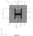
- FIG. 1 illustrates, seen from above, a first example of a device according to the invention.
- This device 2 comprises a planar element 21, here of square shape, and contained in an xy plane also shown on the figure 2 .
- This element 21 includes elements sensitive to bending.
- the elements sensitive to bending may in particular be electronic components, metal tracks, printed circuits or even energy sources.
- the element 21 is hollowed out and receives, in a substantially central manner, a bending limiting element 20. Said element 20 is capable of limiting the bending of the device.
- Element 21 makes it possible to define zones 22 and 23 of element 21, both of which are located in the extension of element 20, along the x axis and along the y axis, in two opposite directions.
- the other areas of element 21 are identified by the references 26 to 28. They are located in the corners of element 21 and are delimited by the dotted lines indicated on the figure 1 .
- This element 20 for limiting bending comprises an elongated central part 25, on either side of which extend projecting parts 24 defining recesses 24a.
- the projecting portions extend into the xy plane.
- element 20 has a certain thickness, just like element 21. They therefore also have a component along a z axis perpendicular to the xy plane, corresponding to this thickness. Thus, the central part extends along an xz plane.
- the bending limitation element 20 will completely prevent the bending of the device 2 relative to any axis parallel to the axis x, at the level of zone 22.
- FIG. 2 illustrates the effect of bending around an axis AA parallel to the y axis on element 21, which extends in the xy plane.
- This element 20 for limiting the bending will also make it possible to limit the bending to a determined radius of curvature, at the level of the zone 23, relative to any axis parallel to the y axis, and therefore to protect components sensitive to the flexion, located at the level of the zone bending 23, too much bending relative to an axis parallel to the y axis which could damage them.
- the limitation of the radius of curvature is obtained by appropriately choosing the width L corresponding to the spacing between two projecting parts and the height H of these projecting parts.
- L and H are chosen such that L ⁇ ⁇ H and, preferably, L ⁇ 2H.
- the elements sensitive to bending cannot be effectively protected from bending relative to any axis parallel to the y axis at the level of zones 28 and 29, nor at the level of zone 23.
- the elements sensitive to bending cannot be effectively protected from bending along any axis parallel to the x axis at the level of zones 26 and 27.
- the bending limitation element 20 illustrated in figure 2 must occupy an equally large surface area, which correspondingly reduces the surface area occupied by the different components of the device.
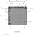
- FIG. 3 illustrates, seen from above, another embodiment of the device according to the invention making it possible to ensure better protection of the components of the device, against bending, whatever the axis relative to which it is product.
- the device 3 is still substantially planar and extends along the xy plane. It also has a certain thickness and therefore a component along the z axis perpendicular to the xy plane. It has a preferably square shape and includes elements sensitive to bending on its surface 37.
- this bending limitation element 30 is composed of two parts 31 and 32 extending in different directions.
- these two parts 31 and 32 are perpendicular and extend along two adjacent sides of the device 3.
- Other configurations could be considered, such as those described with reference to figures 4 to 7 .
- Each part 31 and 32 of the bending limitation element 30 has the same general structure as the bending limiting element 20 illustrated in figure 1 .
- each of them comprises an elongated central part 315, 325, on either side of which extend projecting parts 314, 324, defining recesses 314a, 324a.
- the element 30 makes it possible to limit the bending of the device 3 over its entire surface 37, relative to any axis, parallel to the x axis or the y axis.
- the element 30 defines a substantially square zone 33, the two sides of which are identified by the references 33a and 33b, as well as two zones 35 and 36 corresponding to the part of the surface 37 occupied by the parts 32 and 31 of the element. 30.
- the two sides 33a and 33b correspond to the length of the parts 31 and 32 which have an active role in limiting the bending, that is to say to the length of the central part.
- Zones 35 and 36 are not intended to receive components, to the extent that they are occupied by element 30.
- Part 31 of element 30 makes it possible to limit the bending of the device 3 to a radius of curvature determined at zone 33, relative to any axis parallel to the y axis.
- Part 32 also makes it possible to limit the bending of the device 3 to a radius of curvature determined at zone 33, relative to any axis parallel to the x axis. It is sufficient for this that the height H and the spacing L of the projecting parts are such that L ⁇ ⁇ H and, preferably, L ⁇ 2H.
- the element 30 completely prevents bending at zone 35 with respect to any axis parallel to the y axis, as well as bending at zone 36, with respect to any axis parallel to the x axis.
- the surface occupied by the element 30 limiting the bending will be less than 50% of the total surface of the device 3 and preferably less than 10%.
- the device is intended to be placed on the body of a user. It is therefore advantageous to limit as much as possible the surface occupied by the zones making bending completely impossible.
- the surface occupied by the element 30 limiting the bending could be limited to 15% for parts 31 and 32 whose width is approximately 0.5 cm.
- the minimum radius of curvature with respect to any axis parallel to the x axis and with respect to any axis parallel to the y axis will be less than 5 cm, preferably less than 2 cm.
- Device 4 is, again, square in shape. It extends along the xy plane and has a thickness along the z axis perpendicular to the xy plane.
- the device 4 comprises a bending limitation element 40, made up of two elements 41 and 42. It is arranged inside the device 4.
- These two elements 41 and 42 extend in two different directions, here two perpendicular directions.
- One of the elements 41 extends along one of the sides of the device 4, while the other element 42 extends through the device 4, substantially in a central position.
- this central element 42 makes it possible to define two zones 47 and 48 of the total surface of the device. Each of these zones is an extension of the lateral element 41 along the y axis.
- the device comprises, over its entire surface, elements sensitive to bending, with the exception of zones 43 and 46 occupied by element 40.
- Each of these elements 41, 42 comprises a central part 415, 425, on either side of which extend parts in projection 414, 424.
- the central part 415 extends along the xz plane and the central part 425 extends along the yz plane.
- the bending limitation element 40 makes it possible to protect the elements sensitive to bending by limiting the bending of the device 4 at the level of the entire surface of the device 4 relative to any axis parallel to the x axis or to the y axis.
- Element 40 makes it possible, thanks to element 41, to limit the bending of device 4 to a radius of curvature determined at zones 47 and 48 relative to an axis parallel to the y axis.
- the element 40 also makes it possible to limit the bending of the device 4 to a radius of curvature determined at the level of the zones 47 and 48 relative to an axis parallel to the axis x, thanks to the element 42.
- the height H and the spacing L of the projecting parts are such that L ⁇ ⁇ H and, preferably, L ⁇ 2H.
- the element 40 completely prevents bending at zone 43 along an axis parallel to the y axis, as well as bending at zone 46 relative to any axis parallel to the x axis.
- element 40 is capable of conforming to a part of the human body.
- the surface occupied by the element 40 will always be less than 50% of the total surface of the device 4, preferably less than 10%.
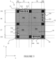
- the device 5 again has a preferably square and substantially planar shape. It defines a surface 50 comprising components sensitive to bending which extends in the xy plane. The device also has a thickness along the z axis perpendicular to the xy plane.
- the elements 51, 52, 53 and 54 have here the same general structure, namely an elongated central part 515, 525, 535 and 545, on either side of which extend projecting parts 514, 524, 534 and 544.
- Each of these elements 51 to 54 is arranged parallel to one side of the device 5, such that its central part is substantially parallel to this side.
- each of the elements 51 to 54 has a length less than that of one side of the device, so that spaces are provided between each of them.
- These bending limitation elements 51, 52, 53 and 54 define several zones in the surface 50: zones 55 and 56 in the extension of elements 51 and 54 along the y axis and zones 57 and 58 in the extension of the elements 52 and 53 along the x axis.
- zone 55 includes zones 55a and 55b, zone 55a being common with zone 58 and zone 55b being common with zone 57.
- zone 56 includes zones 56a and 56b, zone 56a being common with zone 58 and zone 56b being common with zone 57.
- zones 500, 501, 502 and 503 correspond to one side of the surface partially occupied by one of the elements 51 to 54.
- elements 51 to 54 makes it possible to protect the elements sensitive to bending by limiting the bending of the device 5 at the level of the entire surface 50 of the device, along any axis parallel to the x axis or to the y axis.
- the bending limitation element 51 makes it possible to limit the bending of the device 5 to a radius of curvature determined at zone 55 relative to an axis parallel to the y axis.
- Element 51 will completely prevent bending at area 501 relative to any axis parallel to the x axis.
- the bending limitation element 54 makes it possible to limit the bending of the device 5 to a radius of curvature determined at zone 56 along any axis parallel to the y axis.
- Element 54 completely prevents bending at area 503 relative to any axis parallel to the x axis.
- the bending limitation element 53 makes it possible to limit the bending of the device 5 to a radius of curvature determined at zone 57 relative to any axis parallel to the x axis.
- Element 53 completely prevents bending at zone 502 along any axis parallel to the y axis.
- the bending limitation element 52 makes it possible to limit the bending of the device 5 to a radius of curvature determined at zone 58 along any axis parallel to the x axis. Element 52 completely prevents bending at zone 500 along any axis parallel to the y axis.
- the device 6 still has a substantially square and planar shape here. It defines, in the xy plane, a surface 65.
- the device 6 comprises a bending limitation element 60 which is made up of four parts 61, 62, 63 and 64. Each of these parts is arranged along one of the sides of the device and has a length slightly lower than that on each side.
- the element 60 constitutes in practice a single element made up of orthogonal parts in pairs and arranged at the periphery of the device 6.
- the element 60 makes it possible to limit the bending to a radius of curvature determined over the entire surface 65 of the device not occupied by the elements 61 to 64, whether the bending occurs along an axis parallel to the x axis or to the y axis.
- each of the elements 61 and 64 completely prevents bending at the level of the zones 601 and 603, corresponding to the parts of the surface occupied by these elements 61 and 64, with respect to any axis parallel to the x axis and each of the elements 62, 63 completely prevent bending at the areas 600 and 602 occupied by these elements with respect to any axis parallel to the y axis.
- the invention is not limited to the general structure of a bending limitation element which has been described with reference to the figures 1 to 6 .
- Other elements making it possible to limit bending may be used. Indeed, we could imagine modifying the distribution, shape and dimensions of the projecting parts and recesses of these elements.
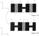
- another bending limitation element may comprise a central part and projecting parts, the central part having different orientations.
- FIG. 11A is a top view (or in the xy plane) of a bending limitation element 1. It comprises four projecting parts 10 to 13 connected in pairs by a central part 14 to 16, these central parts not all having the same orientation.
- the central parts 15 and 16 extend in the xy plane, while the central part 14 extends along the xz plane perpendicular to the xy plane.
- bend limiting members may be designed to limit bending at radii of curvature different from each other.
- the device can consist of a substrate or a housing, both comprising elements sensitive to bending.
- the invention is not limited to the particular locations of the elements limiting the bending which have been described with reference to these figures. These elements could be arranged differently and still fulfill their function, as long as the bending axis does not pass through the central part of the elements.
- the device according to the invention has a planar and square shape.
- the invention is not limited to this embodiment and the device could take other forms.
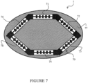
- the device can be presented for example in the form of a rectangle, a triangle or a disk.
- the choice of the shape of the device may depend on different criteria such as the morphology of the person or the area of the human body to be electrically stimulated.
- FIG. 7 An example of an oval-shaped device is shown in Figure 7 .
- a bending limitation element 70 making it possible to limit the bending is provided in the device 7.
- This bending limitation element 70 is here composed of six parts 71 to 76. These six parts are, in practice, connected to each other so as to form only one element.
- the number and length of the different parts could be modified so that the bending limitation element is arranged closer to the periphery of the surface 77, so as to increase the available space that can accommodate bending sensitive elements.
- FIG 8 illustrates a variant in which the bending limitation elements are integrated inside the packaging (or encapsulation box) in which the elements necessary for the production of a skin device according to the invention are housed (batteries, electronic components, metal tracks, etc.).
- this configuration has the advantage that these bending limitation elements are not visible to the user.
- the encapsulation housing 8 comprises two parts 85 and 86.
- two cavities 83 and 84 are present within the housing 8, in which elements 81 and 82 constituting the bending limitation device can be inserted.
- FIG. 8B is a sectional view along an axis parallel to axis VIII-VIII and passing through cavity 83.
- This Figure 8B illustrates an element 82 for limiting bending within the cavity 83 provided in the first part 85 of the housing.
- FIG. 8C is a sectional view along the same axis as Figure 88, of the packaging, composed of two parts 85 and 86.
- FIG. 8C shows that the second part 86 also includes a cavity 87 capable of accommodating the bending limitation element 82.
- a cavity is also defined in which is placed a substantially planar device 800 which comprises elements sensitive to bending.
- the element(s) making it possible to limit the bending can be in contact with the walls of the two parts 85 and 86 of the housing, the cavities then being dimensioned to receive an element, without a space free does not exist.
- Element 81 makes it possible to define a zone 87 of the device 800, in its extension along the x axis, and element 82 makes it possible to define a zone 88, in its extension along the y axis.
- element 81 will make it possible to limit the bending at zone 87 relative to any axis parallel to the x axis and element 82 will make it possible to limit bending at zone 88 relative to an axis any parallel to the y axis.
- zone 89 corresponding to the intersection of the two zones 87 and 88, the components are protected from the effects of bending relative to an axis parallel to the x axis or the y axis.
- figures 9A and 98 represent, seen from above and seen in section along the line AA, another embodiment of the device according to the invention.
- the device 9 is composed of four rigid parts 91, 92, 93 and 94 which are interconnected by flexible parts 95, 96 and 97. All these parts are inside the encapsulation housing. These flexible parts ensure the flexibility of the device 9 with respect to any axis parallel to the y axis, at the level of the zones 900, 901 and 902. Metal tracks making it possible to electrically connect the four rigid parts are present at the level of the flexible zones and constitute elements sensitive to bending.
- each of the rigid parts 91 to 94 has a transverse section (in the xy plane) substantially square and each of the flexible parts 95 to 97 has the shape of a strip.
- the encapsulation box defines, at the level of each rigid part, a wall 98 facing a wall 99, these two walls 98 and 99 being substantially perpendicular to the flexible part connecting two adjacent rigid parts.
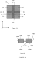
- the device 10 is composed of four rigid parts 101, 102, 103 and 104 and two flexible parts 105 and 106 which connect the rigid parts in pairs.
- each of the rigid parts 101 to 104 has a substantially square section and each of the flexible parts 105, 106 has the shape of a strip, the two flexible parts forming a cross. All these parts of the device are inside an encapsulation case.
- each rigid part comprises two walls of the encapsulation housing 109a and 109b which extend substantially perpendicular to the flexible parts.
- the flexible parts 105 and 106 ensure the flexibility of the device 10 with respect to any axis parallel to the y axis in zone 107 and with respect to any axis parallel to the x axis in zone 108.
- FIG. 10B which is a sectional view along the axis XX, allows us to understand that the walls of the encapsulation box 109a and 109b will make it possible to limit the bending of the device 10 to a determined radius of curvature, when these two walls come into contact due to a bending of the device 10 along an axis parallel to the y axis within zone 107, whether this bending occurs upwards or downwards.
Landscapes
- Health & Medical Sciences (AREA)
- Life Sciences & Earth Sciences (AREA)
- Engineering & Computer Science (AREA)
- Biomedical Technology (AREA)
- Animal Behavior & Ethology (AREA)
- General Health & Medical Sciences (AREA)
- Public Health (AREA)
- Veterinary Medicine (AREA)
- Heart & Thoracic Surgery (AREA)
- Nuclear Medicine, Radiotherapy & Molecular Imaging (AREA)
- Radiology & Medical Imaging (AREA)
- Vascular Medicine (AREA)
- Physics & Mathematics (AREA)
- Pathology (AREA)
- Medical Informatics (AREA)
- Molecular Biology (AREA)
- Surgery (AREA)
- Biophysics (AREA)
- Endoscopes (AREA)
- Supporting Of Heads In Record-Carrier Devices (AREA)
- Prostheses (AREA)
- Media Introduction/Drainage Providing Device (AREA)
- Surgical Instruments (AREA)
Claims (12)
- Vorrichtung, die dazu bestimmt ist, an der Haut eines Benutzers befestigt zu werden, wobei die Vorrichtung im Wesentlichen eben und dadurch gekennzeichnet ist, dass sie umfasst:- mindestens einen biegsamen Bereich, in dem einerseits die Vorrichtung in Bezug auf mindestens zwei in der Ebene der Vorrichtung befindliche Achsen gebogen werden kann, und in dem sich andererseits biegeempfindliche Komponenten befinden,- mindestens zwei Mittel zum Begrenzen der Biegung (31, 32; 41, 42; 51 bis 54, 61 bis 64; 71 bis 76) mit bestimmtem Krümmungsradius, die sich in unterschiedlichen Richtungen erstrecken, wobei die Biegebegrenzungsmittel so konfiguriert sind, dass sie die Biegung des mindestens einen biegsamen Bereichs der Vorrichtung in Bezug auf die mindestens zwei in der Ebene der Vorrichtung befindlichen Achsen begrenzen.
- Vorrichtung nach Anspruch 1, wobei die Biegebegrenzungsmittel (20, 30, 40, 50, 60, 70; 81, 82) einen länglichen Mittelteil (15, 25; 315, 325; 415, 425; 515, 525, 535, 545) umfassen, auf dessen zwei Seiten sich in der Ebene der Vorrichtung vorspringende Teile (14, 24; 314, 324; 414, 424; 515, 524, 534, 544) erstrecken, die zwischen sich Vertiefungen definieren.
- Vorrichtung nach Anspruch 2, wobei die Höhe (H) der vorspringenden Teile und die Breite (L), die dem Abstand zwischen zwei vorspringenden Teilen entsprechen, so sind, dass L < πH und vorzugsweise L < 2H.
- Vorrichtung nach Anspruch 2 oder 3, wobei sich die Biegebegrenzungsmittel in einem im Wesentlichen mittleren Teil der Vorrichtung befinden.
- Vorrichtung nach einem der Ansprüche 2 bis 4, wobei sich die Biegebegrenzungsmittel (30, 40; 51 bis 54; 60; 70) entlang mindestens eines Teils des Umfangs der Vorrichtung befinden.
- Vorrichtung nach Anspruch 5, wobei die Biegebegrenzungsmittel (40) einen Teil (41) umfassen, der sich am Umfang der Vorrichtung befindet, und einen Teil (42), der sich im Wesentlichen in der Mitte der Vorrichtung erstreckt.
- Vorrichtung nach einem der Ansprüche 2 bis 6, wobei die von den Biegebegrenzungsmitteln eingenommene Fläche kleiner als 50 % der Fläche der Vorrichtung und vorzugsweise kleiner als 10 % dieser Fläche ist.
- Vorrichtung nach Anspruch 1, wobei die Biegebegrenzungsmittel von einem Verkapselungsgehäuse der Vorrichtung gebildet werden.
- Vorrichtung nach Anspruch 8, die mindestens zwei starre Teile (91, 92, 93, 94; 101, 102, 103, 104) umfasst, die durch einen biegsamen Bereich (95, 96, 97; 105, 106), in dem sich die biegeempfindlichen Komponenten befinden, miteinander verbunden sind, wobei jeder der starren Teile mindestens zwei Wände des Verkapselungsgehäuses umfasst, wobei die Wände (98, 99; 109a, 109b), die zwei angrenzenden starren Teilen zugewandt sind, die Mittel zur Begrenzung der Biegung in Bezug auf eine Achse darstellen, die sich in dem biegsamen Bereich und parallel zu den Wänden erstreckt.
- Vorrichtung nach Anspruch 9, die eine Vielzahl von starren Teilen (91, 92, 93, 94) umfasst, die durch einen biegsamen Bereich (95, 96, 97) paarweise miteinander verbunden sind und sich in einer bestimmten Richtung erstrecken.
- Vorrichtung nach Anspruch 9, die mindestens vier starre Bereiche (101, 102, 103, 104) umfasst, die durch mindestens zwei biegsame Bereiche (105, 106) miteinander verbunden sind, die sich in zwei unterschiedlichen Richtungen erstrecken.
- Vorrichtung nach einem der Ansprüche 9 bis 11, wobei die Höhe (H) der Wände und die Breite (L) des Abstands zwischen zwei einander zugewandten Wänden so sind, dass L < πH und vorzugsweise L < 2H.
Applications Claiming Priority (2)
| Application Number | Priority Date | Filing Date | Title |
|---|---|---|---|
| FR1454461A FR3020957B1 (fr) | 2014-05-19 | 2014-05-19 | Dispositif cutane, notamment pour application medicale. |
| PCT/IB2015/053456 WO2015177676A1 (fr) | 2014-05-19 | 2015-05-11 | Dispositif cutané comprenant une zone flexible et des moyens de limitation de la flexion |
Publications (3)
| Publication Number | Publication Date |
|---|---|
| EP3145579A1 EP3145579A1 (de) | 2017-03-29 |
| EP3145579C0 EP3145579C0 (de) | 2023-10-04 |
| EP3145579B1 true EP3145579B1 (de) | 2023-10-04 |
Family
ID=51298805
Family Applications (1)
| Application Number | Title | Priority Date | Filing Date |
|---|---|---|---|
| EP15732353.6A Active EP3145579B1 (de) | 2014-05-19 | 2015-05-11 | Gerät für die haut mit einem biegbaren gebiet und mit mitteln zur begrenzung der biegbarkeit |
Country Status (5)
| Country | Link |
|---|---|
| US (1) | US10945666B2 (de) |
| EP (1) | EP3145579B1 (de) |
| CA (1) | CA2948443C (de) |
| FR (1) | FR3020957B1 (de) |
| WO (1) | WO2015177676A1 (de) |
Family Cites Families (22)
| Publication number | Priority date | Publication date | Assignee | Title |
|---|---|---|---|---|
| US3525330A (en) * | 1966-02-24 | 1970-08-25 | Lockheed Aircraft Corp | Surgical garment prescription method and apparatus |
| US3472233A (en) * | 1966-12-02 | 1969-10-14 | Robert I Sarbacher | Electrical muscle stimulator |
| US4202344A (en) * | 1976-10-05 | 1980-05-13 | Harold Mills | Electrocardiograph electrodes and associated assemblies |
| US5329923A (en) * | 1991-02-15 | 1994-07-19 | Lundquist Ingemar H | Torquable catheter |
| JP3040554B2 (ja) * | 1991-10-08 | 2000-05-15 | ジーイー横河メディカルシステム株式会社 | 超音波探触子 |
| ES2111907T3 (es) * | 1992-12-31 | 1998-03-16 | Alza Corp | Sistema de electrotransporte que tiene medios flexibles. |
| US6374143B1 (en) * | 1999-08-18 | 2002-04-16 | Epic Biosonics, Inc. | Modiolar hugging electrode array |
| US20030092978A1 (en) * | 2001-11-13 | 2003-05-15 | Fisher Richard J. | Flexible medical electrode |
| AU2005296341B2 (en) * | 2004-10-19 | 2011-06-30 | Meagan Medical, Inc. | Method and means for electrical stimulation of cutaneous sensory receptors |
| US8700177B2 (en) | 2008-08-01 | 2014-04-15 | Ndi Medical, Llc | Systems and methods for providing percutaneous electrical stimulation |
| US8389862B2 (en) * | 2008-10-07 | 2013-03-05 | Mc10, Inc. | Extremely stretchable electronics |
| US8097926B2 (en) * | 2008-10-07 | 2012-01-17 | Mc10, Inc. | Systems, methods, and devices having stretchable integrated circuitry for sensing and delivering therapy |
| KR20120098725A (ko) * | 2009-10-19 | 2012-09-05 | 바이엘 머티리얼사이언스 아게 | 햅틱 피드백을 위한 굴곡 조립체 및 고정장치 |
| EP2974673B1 (de) * | 2010-03-17 | 2017-03-22 | The Board of Trustees of the University of Illionis | Implantierbare biomedizinische vorrichtungen auf bioresorbierbaren substraten |
| JP5559425B2 (ja) * | 2010-05-12 | 2014-07-23 | イリズム・テクノロジーズ・インコーポレイテッド | 長期粘着用の装置機構及び構成要素 |
| EP2476455A1 (de) * | 2011-01-13 | 2012-07-18 | BIOTRONIK SE & Co. KG | Implantierbare Elektrodenleitung |
| EP2802378A4 (de) | 2012-01-13 | 2015-04-01 | Modular Therapeutx Llc | Tragbare tens-vorrichtung und verwendungsverfahren dafür |
| ES2911462T3 (es) * | 2012-09-04 | 2022-05-19 | Lkc Tech Inc | Matriz de electrodos y procedimiento de medición que lo utiliza |
| US9117347B2 (en) * | 2013-02-25 | 2015-08-25 | Nokia Technologies Oy | Method and apparatus for a flexible housing |
| US9788789B2 (en) * | 2013-08-30 | 2017-10-17 | Thalmic Labs Inc. | Systems, articles, and methods for stretchable printed circuit boards |
| US9795299B2 (en) * | 2013-09-27 | 2017-10-24 | Covidien Lp | Modular physiological sensing patch |
| KR20160085202A (ko) * | 2015-01-07 | 2016-07-15 | 삼성전자주식회사 | 디스플레이장치 |
-
2014
- 2014-05-19 FR FR1454461A patent/FR3020957B1/fr not_active Expired - Fee Related
-
2015
- 2015-05-11 CA CA2948443A patent/CA2948443C/fr active Active
- 2015-05-11 EP EP15732353.6A patent/EP3145579B1/de active Active
- 2015-05-11 WO PCT/IB2015/053456 patent/WO2015177676A1/fr not_active Ceased
- 2015-05-11 US US15/311,121 patent/US10945666B2/en active Active
Also Published As
| Publication number | Publication date |
|---|---|
| US10945666B2 (en) | 2021-03-16 |
| EP3145579C0 (de) | 2023-10-04 |
| FR3020957B1 (fr) | 2021-07-23 |
| CA2948443C (fr) | 2022-09-27 |
| FR3020957A1 (fr) | 2015-11-20 |
| EP3145579A1 (de) | 2017-03-29 |
| US20170079584A1 (en) | 2017-03-23 |
| WO2015177676A1 (fr) | 2015-11-26 |
| CA2948443A1 (fr) | 2015-11-26 |
Similar Documents
| Publication | Publication Date | Title |
|---|---|---|
| EP0034077B1 (de) | Elektromechanische Wandler enthaltende zusammengesetzte Folien und eine solche Folie enthaltende Wandler | |
| EP0121467B1 (de) | Kleinstverbinder mit hoher Kontaktdichtheit | |
| EP0092449A1 (de) | Vorrichtung zur Gesichtsmassage | |
| EP3892325B1 (de) | Autonomes herzimplantat vom typ leadless-kardiokapsel, das ein energierückgewinnungssystem mit piezoelektrischem plättchen umfasst | |
| EP2384788B1 (de) | Schraubenloses Schnellverbindungssystem eines Sondenanschlusses an einen Generator eines implantierbaren Medizingeräts | |
| FR2946231A1 (fr) | Ensemble de malles de transport empilables | |
| CH717520A2 (fr) | Dispositif portable d'analyse continue d'un fluide corporel d'un patient. | |
| CA2949344C (fr) | Connecteur electrique notamment pour dispositif cutane. | |
| CA2948387C (fr) | Dispositif cutane, notamment generateur d'impulsions pour l'electrostimulation | |
| EP3145579B1 (de) | Gerät für die haut mit einem biegbaren gebiet und mit mitteln zur begrenzung der biegbarkeit | |
| EP0136237B1 (de) | Halterung für Gehäuse für eine integrierte Schaltung | |
| EP4248854B1 (de) | Messstation mit griff | |
| CA2308715C (fr) | Dispositif d'application a formes multiples | |
| WO2023126220A1 (fr) | Station de mesure avec mesure de l'activité sudorale | |
| FR3020958A1 (fr) | Dispositif d'electrode cutanee et dispositif d'electrostimulation integrant ce dispositif d'electrode. | |
| EP4162238B1 (de) | Elektronisches messgerät mit elektrode | |
| WO1986003953A1 (fr) | Bigoudi a ondulation permanente | |
| WO2015177725A1 (fr) | Dispositif médical cutané comprenant une partie principale avec une embase et une électrode amovible | |
| EP3158653B1 (de) | Modulare vorrichtung zum positionieren zweier bauteile zueinander | |
| CH718046A2 (fr) | Dispositif portable d'analyse continue d'un fluide corporel d'un patient. | |
| WO2000003760A1 (fr) | Vetement excito-moteur | |
| FR2537349A1 (fr) | Dispositif de connexion a contacts et procede de montage desdits contacts dans le dispositif | |
| EP1248575A1 (de) | Knochenfixateur, insbesondere für die wirbelsäule | |
| WO2021250232A1 (fr) | Dispositif portable d'analyse continue d'un fluide corporel d'un patient | |
| FR2843837A1 (fr) | Connecteur de faible epaisseur pour carte a circuit(s) integre(s) |
Legal Events
| Date | Code | Title | Description |
|---|---|---|---|
| STAA | Information on the status of an ep patent application or granted ep patent |
Free format text: STATUS: THE INTERNATIONAL PUBLICATION HAS BEEN MADE |
|
| PUAI | Public reference made under article 153(3) epc to a published international application that has entered the european phase |
Free format text: ORIGINAL CODE: 0009012 |
|
| STAA | Information on the status of an ep patent application or granted ep patent |
Free format text: STATUS: REQUEST FOR EXAMINATION WAS MADE |
|
| 17P | Request for examination filed |
Effective date: 20161208 |
|
| AK | Designated contracting states |
Kind code of ref document: A1 Designated state(s): AL AT BE BG CH CY CZ DE DK EE ES FI FR GB GR HR HU IE IS IT LI LT LU LV MC MK MT NL NO PL PT RO RS SE SI SK SM TR |
|
| AX | Request for extension of the european patent |
Extension state: BA ME |
|
| DAV | Request for validation of the european patent (deleted) | ||
| DAX | Request for extension of the european patent (deleted) | ||
| STAA | Information on the status of an ep patent application or granted ep patent |
Free format text: STATUS: EXAMINATION IS IN PROGRESS |
|
| 17Q | First examination report despatched |
Effective date: 20190904 |
|
| RIC1 | Information provided on ipc code assigned before grant |
Ipc: A61F 13/00 20060101ALI20230316BHEP Ipc: A61F 13/02 20060101ALI20230316BHEP Ipc: A61N 1/375 20060101ALI20230316BHEP Ipc: A61N 1/04 20060101AFI20230316BHEP |
|
| GRAP | Despatch of communication of intention to grant a patent |
Free format text: ORIGINAL CODE: EPIDOSNIGR1 |
|
| STAA | Information on the status of an ep patent application or granted ep patent |
Free format text: STATUS: GRANT OF PATENT IS INTENDED |
|
| INTG | Intention to grant announced |
Effective date: 20230504 |
|
| GRAS | Grant fee paid |
Free format text: ORIGINAL CODE: EPIDOSNIGR3 |
|
| GRAA | (expected) grant |
Free format text: ORIGINAL CODE: 0009210 |
|
| STAA | Information on the status of an ep patent application or granted ep patent |
Free format text: STATUS: THE PATENT HAS BEEN GRANTED |
|
| AK | Designated contracting states |
Kind code of ref document: B1 Designated state(s): AL AT BE BG CH CY CZ DE DK EE ES FI FR GB GR HR HU IE IS IT LI LT LU LV MC MK MT NL NO PL PT RO RS SE SI SK SM TR |
|
| REG | Reference to a national code |
Ref country code: GB Ref legal event code: FG4D Free format text: NOT ENGLISH |
|
| REG | Reference to a national code |
Ref country code: CH Ref legal event code: EP |
|
| REG | Reference to a national code |
Ref country code: IE Ref legal event code: FG4D Free format text: LANGUAGE OF EP DOCUMENT: FRENCH |
|
| REG | Reference to a national code |
Ref country code: DE Ref legal event code: R096 Ref document number: 602015085934 Country of ref document: DE |
|
| U01 | Request for unitary effect filed |
Effective date: 20231016 |
|
| U07 | Unitary effect registered |
Designated state(s): AT BE BG DE DK EE FI FR IT LT LU LV MT NL PT SE SI Effective date: 20231024 |
|
| PG25 | Lapsed in a contracting state [announced via postgrant information from national office to epo] |
Ref country code: GR Free format text: LAPSE BECAUSE OF FAILURE TO SUBMIT A TRANSLATION OF THE DESCRIPTION OR TO PAY THE FEE WITHIN THE PRESCRIBED TIME-LIMIT Effective date: 20240105 |
|
| PG25 | Lapsed in a contracting state [announced via postgrant information from national office to epo] |
Ref country code: IS Free format text: LAPSE BECAUSE OF FAILURE TO SUBMIT A TRANSLATION OF THE DESCRIPTION OR TO PAY THE FEE WITHIN THE PRESCRIBED TIME-LIMIT Effective date: 20240204 |
|
| PG25 | Lapsed in a contracting state [announced via postgrant information from national office to epo] |
Ref country code: ES Free format text: LAPSE BECAUSE OF FAILURE TO SUBMIT A TRANSLATION OF THE DESCRIPTION OR TO PAY THE FEE WITHIN THE PRESCRIBED TIME-LIMIT Effective date: 20231004 |
|
| PG25 | Lapsed in a contracting state [announced via postgrant information from national office to epo] |
Ref country code: IS Free format text: LAPSE BECAUSE OF FAILURE TO SUBMIT A TRANSLATION OF THE DESCRIPTION OR TO PAY THE FEE WITHIN THE PRESCRIBED TIME-LIMIT Effective date: 20240204 Ref country code: GR Free format text: LAPSE BECAUSE OF FAILURE TO SUBMIT A TRANSLATION OF THE DESCRIPTION OR TO PAY THE FEE WITHIN THE PRESCRIBED TIME-LIMIT Effective date: 20240105 Ref country code: ES Free format text: LAPSE BECAUSE OF FAILURE TO SUBMIT A TRANSLATION OF THE DESCRIPTION OR TO PAY THE FEE WITHIN THE PRESCRIBED TIME-LIMIT Effective date: 20231004 |
|
| PG25 | Lapsed in a contracting state [announced via postgrant information from national office to epo] |
Ref country code: RS Free format text: LAPSE BECAUSE OF FAILURE TO SUBMIT A TRANSLATION OF THE DESCRIPTION OR TO PAY THE FEE WITHIN THE PRESCRIBED TIME-LIMIT Effective date: 20231004 Ref country code: PL Free format text: LAPSE BECAUSE OF FAILURE TO SUBMIT A TRANSLATION OF THE DESCRIPTION OR TO PAY THE FEE WITHIN THE PRESCRIBED TIME-LIMIT Effective date: 20231004 Ref country code: NO Free format text: LAPSE BECAUSE OF FAILURE TO SUBMIT A TRANSLATION OF THE DESCRIPTION OR TO PAY THE FEE WITHIN THE PRESCRIBED TIME-LIMIT Effective date: 20240104 Ref country code: HR Free format text: LAPSE BECAUSE OF FAILURE TO SUBMIT A TRANSLATION OF THE DESCRIPTION OR TO PAY THE FEE WITHIN THE PRESCRIBED TIME-LIMIT Effective date: 20231004 |
|
| U20 | Renewal fee for the european patent with unitary effect paid |
Year of fee payment: 10 Effective date: 20240522 |
|
| REG | Reference to a national code |
Ref country code: DE Ref legal event code: R097 Ref document number: 602015085934 Country of ref document: DE |
|
| PG25 | Lapsed in a contracting state [announced via postgrant information from national office to epo] |
Ref country code: CZ Free format text: LAPSE BECAUSE OF FAILURE TO SUBMIT A TRANSLATION OF THE DESCRIPTION OR TO PAY THE FEE WITHIN THE PRESCRIBED TIME-LIMIT Effective date: 20231004 |
|
| PG25 | Lapsed in a contracting state [announced via postgrant information from national office to epo] |
Ref country code: SK Free format text: LAPSE BECAUSE OF FAILURE TO SUBMIT A TRANSLATION OF THE DESCRIPTION OR TO PAY THE FEE WITHIN THE PRESCRIBED TIME-LIMIT Effective date: 20231004 |
|
| PG25 | Lapsed in a contracting state [announced via postgrant information from national office to epo] |
Ref country code: SM Free format text: LAPSE BECAUSE OF FAILURE TO SUBMIT A TRANSLATION OF THE DESCRIPTION OR TO PAY THE FEE WITHIN THE PRESCRIBED TIME-LIMIT Effective date: 20231004 Ref country code: SK Free format text: LAPSE BECAUSE OF FAILURE TO SUBMIT A TRANSLATION OF THE DESCRIPTION OR TO PAY THE FEE WITHIN THE PRESCRIBED TIME-LIMIT Effective date: 20231004 Ref country code: RO Free format text: LAPSE BECAUSE OF FAILURE TO SUBMIT A TRANSLATION OF THE DESCRIPTION OR TO PAY THE FEE WITHIN THE PRESCRIBED TIME-LIMIT Effective date: 20231004 Ref country code: CZ Free format text: LAPSE BECAUSE OF FAILURE TO SUBMIT A TRANSLATION OF THE DESCRIPTION OR TO PAY THE FEE WITHIN THE PRESCRIBED TIME-LIMIT Effective date: 20231004 |
|
| PLBE | No opposition filed within time limit |
Free format text: ORIGINAL CODE: 0009261 |
|
| STAA | Information on the status of an ep patent application or granted ep patent |
Free format text: STATUS: NO OPPOSITION FILED WITHIN TIME LIMIT |
|
| 26N | No opposition filed |
Effective date: 20240705 |
|
| U1H | Name or address of the proprietor changed after the registration of the unitary effect |
Owner name: COMMISSARIAT A L'ENERGIE ATOMIQUE ET AUX ENERGIESALTERNATIVES; FR |
|
| REG | Reference to a national code |
Ref country code: CH Ref legal event code: PL |
|
| PG25 | Lapsed in a contracting state [announced via postgrant information from national office to epo] |
Ref country code: MC Free format text: LAPSE BECAUSE OF FAILURE TO SUBMIT A TRANSLATION OF THE DESCRIPTION OR TO PAY THE FEE WITHIN THE PRESCRIBED TIME-LIMIT Effective date: 20231004 |
|
| GBPC | Gb: european patent ceased through non-payment of renewal fee |
Effective date: 20240511 |
|
| PG25 | Lapsed in a contracting state [announced via postgrant information from national office to epo] |
Ref country code: MC Free format text: LAPSE BECAUSE OF FAILURE TO SUBMIT A TRANSLATION OF THE DESCRIPTION OR TO PAY THE FEE WITHIN THE PRESCRIBED TIME-LIMIT Effective date: 20231004 Ref country code: CH Free format text: LAPSE BECAUSE OF NON-PAYMENT OF DUE FEES Effective date: 20240531 |
|
| PG25 | Lapsed in a contracting state [announced via postgrant information from national office to epo] |
Ref country code: IE Free format text: LAPSE BECAUSE OF NON-PAYMENT OF DUE FEES Effective date: 20240511 |
|
| PG25 | Lapsed in a contracting state [announced via postgrant information from national office to epo] |
Ref country code: GB Free format text: LAPSE BECAUSE OF NON-PAYMENT OF DUE FEES Effective date: 20240511 |
|
| U20 | Renewal fee for the european patent with unitary effect paid |
Year of fee payment: 11 Effective date: 20250520 |
|
| PG25 | Lapsed in a contracting state [announced via postgrant information from national office to epo] |
Ref country code: CY Free format text: LAPSE BECAUSE OF FAILURE TO SUBMIT A TRANSLATION OF THE DESCRIPTION OR TO PAY THE FEE WITHIN THE PRESCRIBED TIME-LIMIT; INVALID AB INITIO Effective date: 20150511 |
|
| PG25 | Lapsed in a contracting state [announced via postgrant information from national office to epo] |
Ref country code: HU Free format text: LAPSE BECAUSE OF FAILURE TO SUBMIT A TRANSLATION OF THE DESCRIPTION OR TO PAY THE FEE WITHIN THE PRESCRIBED TIME-LIMIT; INVALID AB INITIO Effective date: 20150511 |