EP3145559B1 - Blutpumpe - Google Patents
Blutpumpe Download PDFInfo
- Publication number
- EP3145559B1 EP3145559B1 EP15753493.4A EP15753493A EP3145559B1 EP 3145559 B1 EP3145559 B1 EP 3145559B1 EP 15753493 A EP15753493 A EP 15753493A EP 3145559 B1 EP3145559 B1 EP 3145559B1
- Authority
- EP
- European Patent Office
- Prior art keywords
- blood
- subject
- pump
- vena cava
- downstream
- Prior art date
- Legal status (The legal status is an assumption and is not a legal conclusion. Google has not performed a legal analysis and makes no representation as to the accuracy of the status listed.)
- Active
Links
- 210000004369 blood Anatomy 0.000 title claims description 88
- 239000008280 blood Substances 0.000 title claims description 88
- 238000011144 upstream manufacturing Methods 0.000 claims description 105
- 210000002796 renal vein Anatomy 0.000 claims description 73
- 210000004204 blood vessel Anatomy 0.000 claims description 36
- 230000017531 blood circulation Effects 0.000 claims description 25
- 210000003462 vein Anatomy 0.000 claims description 21
- 230000036772 blood pressure Effects 0.000 claims description 19
- 238000005086 pumping Methods 0.000 claims description 16
- 230000004044 response Effects 0.000 claims description 11
- 210000003191 femoral vein Anatomy 0.000 claims description 9
- 210000004731 jugular vein Anatomy 0.000 claims description 9
- 210000001321 subclavian vein Anatomy 0.000 claims description 9
- 239000000463 material Substances 0.000 claims description 2
- 238000000926 separation method Methods 0.000 claims 2
- 230000001965 increasing effect Effects 0.000 description 19
- 206010019280 Heart failures Diseases 0.000 description 13
- 230000010412 perfusion Effects 0.000 description 12
- 230000004064 dysfunction Effects 0.000 description 11
- 206010007559 Cardiac failure congestive Diseases 0.000 description 10
- 230000000694 effects Effects 0.000 description 10
- 206010062237 Renal impairment Diseases 0.000 description 9
- 230000000747 cardiac effect Effects 0.000 description 9
- 239000002934 diuretic Substances 0.000 description 9
- 229940030606 diuretics Drugs 0.000 description 9
- 230000005977 kidney dysfunction Effects 0.000 description 9
- 238000000034 method Methods 0.000 description 9
- 210000001367 artery Anatomy 0.000 description 8
- 230000009467 reduction Effects 0.000 description 8
- 210000003734 kidney Anatomy 0.000 description 7
- 102000002723 Atrial Natriuretic Factor Human genes 0.000 description 6
- 101800001288 Atrial natriuretic factor Proteins 0.000 description 6
- 101800001890 Atrial natriuretic peptide Proteins 0.000 description 6
- 101800000407 Brain natriuretic peptide 32 Proteins 0.000 description 6
- NSQLIUXCMFBZME-MPVJKSABSA-N carperitide Chemical compound C([C@H]1C(=O)NCC(=O)NCC(=O)N[C@@H](CCCNC(N)=N)C(=O)N[C@@H](CCSC)C(=O)N[C@@H](CC(O)=O)C(=O)N[C@@H](CCCNC(N)=N)C(=O)N[C@H](C(NCC(=O)N[C@@H](C)C(=O)N[C@@H](CCC(N)=O)C(=O)N[C@@H](CO)C(=O)NCC(=O)N[C@@H](CC(C)C)C(=O)NCC(=O)N[C@@H](CSSC[C@@H](C(=O)N1)NC(=O)[C@H](CO)NC(=O)[C@H](CO)NC(=O)[C@H](CCCNC(N)=N)NC(=O)[C@H](CCCNC(N)=N)NC(=O)[C@H](CC(C)C)NC(=O)[C@@H](N)CO)C(=O)N[C@@H](CC(N)=O)C(=O)N[C@@H](CO)C(=O)N[C@@H](CC=1C=CC=CC=1)C(=O)N[C@@H](CCCNC(N)=N)C(=O)N[C@@H](CC=1C=CC(O)=CC=1)C(O)=O)=O)[C@@H](C)CC)C1=CC=CC=C1 NSQLIUXCMFBZME-MPVJKSABSA-N 0.000 description 6
- 210000000056 organ Anatomy 0.000 description 6
- 210000002254 renal artery Anatomy 0.000 description 6
- 230000002792 vascular Effects 0.000 description 6
- 210000001631 vena cava inferior Anatomy 0.000 description 6
- 230000004913 activation Effects 0.000 description 5
- 230000008327 renal blood flow Effects 0.000 description 5
- 210000000709 aorta Anatomy 0.000 description 4
- 208000037849 arterial hypertension Diseases 0.000 description 4
- 206010012601 diabetes mellitus Diseases 0.000 description 4
- 230000002644 neurohormonal effect Effects 0.000 description 4
- 230000029142 excretion Effects 0.000 description 3
- 239000012530 fluid Substances 0.000 description 3
- 230000009885 systemic effect Effects 0.000 description 3
- 206010020565 Hyperaemia Diseases 0.000 description 2
- DGAQECJNVWCQMB-PUAWFVPOSA-M Ilexoside XXIX Chemical compound C[C@@H]1CC[C@@]2(CC[C@@]3(C(=CC[C@H]4[C@]3(CC[C@@H]5[C@@]4(CC[C@@H](C5(C)C)OS(=O)(=O)[O-])C)C)[C@@H]2[C@]1(C)O)C)C(=O)O[C@H]6[C@@H]([C@H]([C@@H]([C@H](O6)CO)O)O)O.[Na+] DGAQECJNVWCQMB-PUAWFVPOSA-M 0.000 description 2
- XEEYBQQBJWHFJM-UHFFFAOYSA-N Iron Chemical compound [Fe] XEEYBQQBJWHFJM-UHFFFAOYSA-N 0.000 description 2
- 230000003213 activating effect Effects 0.000 description 2
- 238000004891 communication Methods 0.000 description 2
- DDRJAANPRJIHGJ-UHFFFAOYSA-N creatinine Chemical compound CN1CC(=O)NC1=N DDRJAANPRJIHGJ-UHFFFAOYSA-N 0.000 description 2
- 230000002708 enhancing effect Effects 0.000 description 2
- 230000006870 function Effects 0.000 description 2
- 230000024924 glomerular filtration Effects 0.000 description 2
- 230000000977 initiatory effect Effects 0.000 description 2
- 230000007246 mechanism Effects 0.000 description 2
- 230000037361 pathway Effects 0.000 description 2
- 230000008288 physiological mechanism Effects 0.000 description 2
- 230000004043 responsiveness Effects 0.000 description 2
- 229910052708 sodium Inorganic materials 0.000 description 2
- 239000011734 sodium Substances 0.000 description 2
- 238000000108 ultra-filtration Methods 0.000 description 2
- 230000009724 venous congestion Effects 0.000 description 2
- PQSUYGKTWSAVDQ-ZVIOFETBSA-N Aldosterone Chemical compound C([C@@]1([C@@H](C(=O)CO)CC[C@H]1[C@@H]1CC2)C=O)[C@H](O)[C@@H]1[C@]1(C)C2=CC(=O)CC1 PQSUYGKTWSAVDQ-ZVIOFETBSA-N 0.000 description 1
- PQSUYGKTWSAVDQ-UHFFFAOYSA-N Aldosterone Natural products C1CC2C3CCC(C(=O)CO)C3(C=O)CC(O)C2C2(C)C1=CC(=O)CC2 PQSUYGKTWSAVDQ-UHFFFAOYSA-N 0.000 description 1
- 206010003445 Ascites Diseases 0.000 description 1
- 208000037157 Azotemia Diseases 0.000 description 1
- 208000004990 Cardiorenal syndrome Diseases 0.000 description 1
- 102000003951 Erythropoietin Human genes 0.000 description 1
- 108090000394 Erythropoietin Proteins 0.000 description 1
- 206010016803 Fluid overload Diseases 0.000 description 1
- 206010059484 Haemodilution Diseases 0.000 description 1
- 102100028255 Renin Human genes 0.000 description 1
- 108090000783 Renin Proteins 0.000 description 1
- 230000035508 accumulation Effects 0.000 description 1
- 238000009825 accumulation Methods 0.000 description 1
- 230000001154 acute effect Effects 0.000 description 1
- 229960002478 aldosterone Drugs 0.000 description 1
- 238000004873 anchoring Methods 0.000 description 1
- 208000007502 anemia Diseases 0.000 description 1
- 230000003042 antagnostic effect Effects 0.000 description 1
- 230000001746 atrial effect Effects 0.000 description 1
- 210000002665 bowman capsule Anatomy 0.000 description 1
- 230000008859 change Effects 0.000 description 1
- 230000001684 chronic effect Effects 0.000 description 1
- 230000004087 circulation Effects 0.000 description 1
- 230000006835 compression Effects 0.000 description 1
- 238000007906 compression Methods 0.000 description 1
- 238000004590 computer program Methods 0.000 description 1
- 239000002872 contrast media Substances 0.000 description 1
- 229940109239 creatinine Drugs 0.000 description 1
- 230000007423 decrease Effects 0.000 description 1
- 230000006866 deterioration Effects 0.000 description 1
- 230000003205 diastolic effect Effects 0.000 description 1
- 238000006073 displacement reaction Methods 0.000 description 1
- 238000005516 engineering process Methods 0.000 description 1
- 229940105423 erythropoietin Drugs 0.000 description 1
- 230000002496 gastric effect Effects 0.000 description 1
- 238000010438 heat treatment Methods 0.000 description 1
- 230000002440 hepatic effect Effects 0.000 description 1
- 210000002989 hepatic vein Anatomy 0.000 description 1
- 238000003384 imaging method Methods 0.000 description 1
- 230000028709 inflammatory response Effects 0.000 description 1
- 238000007912 intraperitoneal administration Methods 0.000 description 1
- 229910052742 iron Inorganic materials 0.000 description 1
- 210000004185 liver Anatomy 0.000 description 1
- 238000004519 manufacturing process Methods 0.000 description 1
- 210000003205 muscle Anatomy 0.000 description 1
- HLXZNVUGXRDIFK-UHFFFAOYSA-N nickel titanium Chemical compound [Ti].[Ti].[Ti].[Ti].[Ti].[Ti].[Ti].[Ti].[Ti].[Ti].[Ti].[Ni].[Ni].[Ni].[Ni].[Ni].[Ni].[Ni].[Ni].[Ni].[Ni].[Ni].[Ni].[Ni].[Ni] HLXZNVUGXRDIFK-UHFFFAOYSA-N 0.000 description 1
- 229910001000 nickel titanium Inorganic materials 0.000 description 1
- 230000001991 pathophysiological effect Effects 0.000 description 1
- 230000037081 physical activity Effects 0.000 description 1
- 229920000728 polyester Polymers 0.000 description 1
- 229920000642 polymer Polymers 0.000 description 1
- 229920002635 polyurethane Polymers 0.000 description 1
- 239000004814 polyurethane Substances 0.000 description 1
- OXCMYAYHXIHQOA-UHFFFAOYSA-N potassium;[2-butyl-5-chloro-3-[[4-[2-(1,2,4-triaza-3-azanidacyclopenta-1,4-dien-5-yl)phenyl]phenyl]methyl]imidazol-4-yl]methanol Chemical compound [K+].CCCCC1=NC(Cl)=C(CO)N1CC1=CC=C(C=2C(=CC=CC=2)C2=N[N-]N=N2)C=C1 OXCMYAYHXIHQOA-UHFFFAOYSA-N 0.000 description 1
- 102000004169 proteins and genes Human genes 0.000 description 1
- 108090000623 proteins and genes Proteins 0.000 description 1
- 230000005855 radiation Effects 0.000 description 1
- 238000010992 reflux Methods 0.000 description 1
- 208000024891 symptom Diseases 0.000 description 1
- 230000002195 synergetic effect Effects 0.000 description 1
- 238000012285 ultrasound imaging Methods 0.000 description 1
- 210000002700 urine Anatomy 0.000 description 1
Images


Classifications
-
- A—HUMAN NECESSITIES
- A61—MEDICAL OR VETERINARY SCIENCE; HYGIENE
- A61M—DEVICES FOR INTRODUCING MEDIA INTO, OR ONTO, THE BODY; DEVICES FOR TRANSDUCING BODY MEDIA OR FOR TAKING MEDIA FROM THE BODY; DEVICES FOR PRODUCING OR ENDING SLEEP OR STUPOR
- A61M60/00—Blood pumps; Devices for mechanical circulatory actuation; Balloon pumps for circulatory assistance
- A61M60/30—Medical purposes thereof other than the enhancement of the cardiac output
- A61M60/31—Medical purposes thereof other than the enhancement of the cardiac output for enhancement of in vivo organ perfusion, e.g. retroperfusion
- A61M60/33—Medical purposes thereof other than the enhancement of the cardiac output for enhancement of in vivo organ perfusion, e.g. retroperfusion of kidneys
-
- A—HUMAN NECESSITIES
- A61—MEDICAL OR VETERINARY SCIENCE; HYGIENE
- A61M—DEVICES FOR INTRODUCING MEDIA INTO, OR ONTO, THE BODY; DEVICES FOR TRANSDUCING BODY MEDIA OR FOR TAKING MEDIA FROM THE BODY; DEVICES FOR PRODUCING OR ENDING SLEEP OR STUPOR
- A61M60/00—Blood pumps; Devices for mechanical circulatory actuation; Balloon pumps for circulatory assistance
- A61M60/80—Constructional details other than related to driving
- A61M60/802—Constructional details other than related to driving of non-positive displacement blood pumps
- A61M60/81—Pump housings
-
- A—HUMAN NECESSITIES
- A61—MEDICAL OR VETERINARY SCIENCE; HYGIENE
- A61M—DEVICES FOR INTRODUCING MEDIA INTO, OR ONTO, THE BODY; DEVICES FOR TRANSDUCING BODY MEDIA OR FOR TAKING MEDIA FROM THE BODY; DEVICES FOR PRODUCING OR ENDING SLEEP OR STUPOR
- A61M60/00—Blood pumps; Devices for mechanical circulatory actuation; Balloon pumps for circulatory assistance
- A61M60/10—Location thereof with respect to the patient's body
- A61M60/122—Implantable pumps or pumping devices, i.e. the blood being pumped inside the patient's body
- A61M60/126—Implantable pumps or pumping devices, i.e. the blood being pumped inside the patient's body implantable via, into, inside, in line, branching on, or around a blood vessel
- A61M60/13—Implantable pumps or pumping devices, i.e. the blood being pumped inside the patient's body implantable via, into, inside, in line, branching on, or around a blood vessel by means of a catheter allowing explantation, e.g. catheter pumps temporarily introduced via the vascular system
-
- A—HUMAN NECESSITIES
- A61—MEDICAL OR VETERINARY SCIENCE; HYGIENE
- A61M—DEVICES FOR INTRODUCING MEDIA INTO, OR ONTO, THE BODY; DEVICES FOR TRANSDUCING BODY MEDIA OR FOR TAKING MEDIA FROM THE BODY; DEVICES FOR PRODUCING OR ENDING SLEEP OR STUPOR
- A61M60/00—Blood pumps; Devices for mechanical circulatory actuation; Balloon pumps for circulatory assistance
- A61M60/20—Type thereof
- A61M60/205—Non-positive displacement blood pumps
- A61M60/216—Non-positive displacement blood pumps including a rotating member acting on the blood, e.g. impeller
-
- A—HUMAN NECESSITIES
- A61—MEDICAL OR VETERINARY SCIENCE; HYGIENE
- A61M—DEVICES FOR INTRODUCING MEDIA INTO, OR ONTO, THE BODY; DEVICES FOR TRANSDUCING BODY MEDIA OR FOR TAKING MEDIA FROM THE BODY; DEVICES FOR PRODUCING OR ENDING SLEEP OR STUPOR
- A61M60/00—Blood pumps; Devices for mechanical circulatory actuation; Balloon pumps for circulatory assistance
- A61M60/30—Medical purposes thereof other than the enhancement of the cardiac output
- A61M60/34—Medical purposes thereof other than the enhancement of the cardiac output for enhancement of circulation to the extremities, e.g. the feet
-
- A—HUMAN NECESSITIES
- A61—MEDICAL OR VETERINARY SCIENCE; HYGIENE
- A61M—DEVICES FOR INTRODUCING MEDIA INTO, OR ONTO, THE BODY; DEVICES FOR TRANSDUCING BODY MEDIA OR FOR TAKING MEDIA FROM THE BODY; DEVICES FOR PRODUCING OR ENDING SLEEP OR STUPOR
- A61M60/00—Blood pumps; Devices for mechanical circulatory actuation; Balloon pumps for circulatory assistance
- A61M60/80—Constructional details other than related to driving
- A61M60/802—Constructional details other than related to driving of non-positive displacement blood pumps
- A61M60/804—Impellers
- A61M60/806—Vanes or blades
-
- A—HUMAN NECESSITIES
- A61—MEDICAL OR VETERINARY SCIENCE; HYGIENE
- A61F—FILTERS IMPLANTABLE INTO BLOOD VESSELS; PROSTHESES; DEVICES PROVIDING PATENCY TO, OR PREVENTING COLLAPSING OF, TUBULAR STRUCTURES OF THE BODY, e.g. STENTS; ORTHOPAEDIC, NURSING OR CONTRACEPTIVE DEVICES; FOMENTATION; TREATMENT OR PROTECTION OF EYES OR EARS; BANDAGES, DRESSINGS OR ABSORBENT PADS; FIRST-AID KITS
- A61F2/00—Filters implantable into blood vessels; Prostheses, i.e. artificial substitutes or replacements for parts of the body; Appliances for connecting them with the body; Devices providing patency to, or preventing collapsing of, tubular structures of the body, e.g. stents
- A61F2/02—Prostheses implantable into the body
- A61F2/04—Hollow or tubular parts of organs, e.g. bladders, tracheae, bronchi or bile ducts
- A61F2/06—Blood vessels
- A61F2002/068—Modifying the blood flow model, e.g. by diffuser or deflector
-
- A—HUMAN NECESSITIES
- A61—MEDICAL OR VETERINARY SCIENCE; HYGIENE
- A61M—DEVICES FOR INTRODUCING MEDIA INTO, OR ONTO, THE BODY; DEVICES FOR TRANSDUCING BODY MEDIA OR FOR TAKING MEDIA FROM THE BODY; DEVICES FOR PRODUCING OR ENDING SLEEP OR STUPOR
- A61M60/00—Blood pumps; Devices for mechanical circulatory actuation; Balloon pumps for circulatory assistance
- A61M60/10—Location thereof with respect to the patient's body
- A61M60/122—Implantable pumps or pumping devices, i.e. the blood being pumped inside the patient's body
- A61M60/126—Implantable pumps or pumping devices, i.e. the blood being pumped inside the patient's body implantable via, into, inside, in line, branching on, or around a blood vessel
- A61M60/148—Implantable pumps or pumping devices, i.e. the blood being pumped inside the patient's body implantable via, into, inside, in line, branching on, or around a blood vessel in line with a blood vessel using resection or like techniques, e.g. permanent endovascular heart assist devices
-
- A—HUMAN NECESSITIES
- A61—MEDICAL OR VETERINARY SCIENCE; HYGIENE
- A61M—DEVICES FOR INTRODUCING MEDIA INTO, OR ONTO, THE BODY; DEVICES FOR TRANSDUCING BODY MEDIA OR FOR TAKING MEDIA FROM THE BODY; DEVICES FOR PRODUCING OR ENDING SLEEP OR STUPOR
- A61M60/00—Blood pumps; Devices for mechanical circulatory actuation; Balloon pumps for circulatory assistance
- A61M60/40—Details relating to driving
- A61M60/403—Details relating to driving for non-positive displacement blood pumps
- A61M60/408—Details relating to driving for non-positive displacement blood pumps the force acting on the blood contacting member being mechanical, e.g. transmitted by a shaft or cable
- A61M60/411—Details relating to driving for non-positive displacement blood pumps the force acting on the blood contacting member being mechanical, e.g. transmitted by a shaft or cable generated by an electromotor
- A61M60/414—Details relating to driving for non-positive displacement blood pumps the force acting on the blood contacting member being mechanical, e.g. transmitted by a shaft or cable generated by an electromotor transmitted by a rotating cable, e.g. for blood pumps mounted on a catheter
-
- A—HUMAN NECESSITIES
- A61—MEDICAL OR VETERINARY SCIENCE; HYGIENE
- A61M—DEVICES FOR INTRODUCING MEDIA INTO, OR ONTO, THE BODY; DEVICES FOR TRANSDUCING BODY MEDIA OR FOR TAKING MEDIA FROM THE BODY; DEVICES FOR PRODUCING OR ENDING SLEEP OR STUPOR
- A61M60/00—Blood pumps; Devices for mechanical circulatory actuation; Balloon pumps for circulatory assistance
- A61M60/80—Constructional details other than related to driving
- A61M60/802—Constructional details other than related to driving of non-positive displacement blood pumps
- A61M60/833—Occluders for preventing backflow
Definitions
- Some applications of the present invention generally relate to medical apparatus. Specifically, some applications of the present invention relate to apparatus and methods associated with placing a pump in one or more of a subject's renal veins, and/or in the subject's vena cava.
- cardiac dysfunction or congestive heart failure It is common for cardiac dysfunction or congestive heart failure to develop into kidney dysfunction, which in turn, causes congestive heart failure symptoms to develop or worsen.
- systolic and/or diastolic cardiac dysfunction causes systemic venous congestion, which gives rise to an increase in renal venous and interstitial pressure.
- the increase in the pressure causes fluid retention by the body to increase due both to kidney dysfunction and renal neurohormonal activation, both of which typically develop as a result of the increase in renal venous and interstitial pressure.
- the resulting fluid retention causes congestive heart failure to develop or worsen, by causing a blood volume overload at the heart and/or by increasing systemic resistance.
- kidney dysfunction and/or renal neurohormonal activation it is common for kidney dysfunction and/or renal neurohormonal activation to develop into cardiac dysfunction and/or congestive heart failure.
- This pathophysiological cycle in which cardiac dysfunction and/or congestive heart failure leads to kidney dysfunction and/or renal neurohormonal activation, or in which kidney dysfunction and/or renal neurohormonal activation leads to cardiac dysfunction and/or congestive heart failure, each dysfunction leading to deterioration in the other dysfunction, is called the cardio-renal syndrome.
- Increased renal venous pressure has been experimentally shown to cause azotemia, and a reduction in glomerular filtration rate, renal blood flow, urine output, and sodium excretion. It has also been shown to increase plasma renin and aldosterone, and protein excretion. Venous congestion may also contribute to anemia via three different pathways: A reduction in the kidney's erythropoietin production, hemodilution by fluid retention, and an inflammatory response leading to a reduced gastro-intestinal iron uptake.
- increased renal venous pressure may cause intracapsular pressure and, subsequently interstitial peritubular pressure, to rise. A rise in peritubular pressure may impact tubular function (reduce sodium excretion), as well as diminish glomerular filtration by raising the pressure in the Bowman capsule.
- increased renal venous pressure may not only result from increased central venous (right atrial) pressure, but also from intraperitoneal fluid accumulations (ascites) exerting direct pressure on the renal veins.
- Reduction of intraabdominal pressure in heart failure patients by removal of fluid has been shown to reduce plasma creatinine levels.
- Increased venous return resulting from activation of the "leg muscle pump” during physical activity such as walking may raise systemic venous pressure, particularly in heart failure patients, and may result in reflux into the renal veins.
- WO-A-0183016 discloses apparatus for treating congestive heart by actively of passively enhancing perfusion to the renal arteries.
- US-A-2007/208291 discloses a catheter inserted into the aorta of the patient has an outlet port that supplies the patient's blood obtained from a patient's aorta into an adjoining renal artery of the patient to perfuse the kidney.
- the catheter comprises a rotor housed inside a portion of the catheter to supply the blood to the kidney at a desired pressure.
- a subject is identified as suffering from cardiac dysfunction, congestive heart failure, reduced renal blood flow, increased renal vascular resistance, arterial hypertension, diabetes, and/or kidney dysfunction.
- blood pressure within the subject's renal veins is reduced by placing at least one pump in the subject's vena cava, and generating a low- pressure region within the subject's vena cava adjacent to junctions of the vena cava with the subject's renal veins, by activating the pump to pump blood away from the region.
- the pump is activated such that blood pressure within the low-pressure region is lower than central venous pressure of the subject.
- a downstream pump is placed within the vena cava downstream of the junctions of the vena cava with the subject's renal veins, and the pump pumps blood through the vena cava in the downstream direction, away from the junctions.
- an upstream pump is placed within the vena cava upstream of the junctions of the vena cava with the subject's renal veins, and the pump pumps blood through the vena cava in the upstream direction, away from the junctions.
- an occlusion element such as a balloon or a covered stent is placed in the vena cava upstream of the junctions, and is configured to partially occlude the vena cava upstream of the junctions.
- the upstream and downstream pumps are disposed on a single catheter.
- the catheter is inserted into the vena cava via a venous pathway, e.g., via the femoral vein, via the subclavian vein, or via the jugular vein.
- the upstream pump, or the occlusion element is disposed on a first catheter, which is inserted via a vein that is below the subject's inferior vena cava (e.g., the femoral vein), and the downstream pump is disposed on a second catheter, which is inserted via a vein that is above the subject's inferior vena cava (e.g., the subclavian vein, or the jugular vein).
- the downstream pump and/or the upstream pump includes an impeller and a cage.
- impellers of the downstream and the upstream pumps rotate in the same direction, but the downstream pump is configured to pump blood in the downstream direction and the upstream pump is configured to pump blood in the upstream direction.
- a single motor is used to impart rotational motion to both of the impellers, and there is a shaft disposed between the impellers that imparts rotational motion from a first one of the impellers to a second one of the impellers.
- the impellers of the upstream and the downstream pumps are (a) of opposing handedness with respect to one another (i.e., one of the impellers is a left-handed impeller, and the other impeller is a right-handed impeller), and (b) are disposed upon the aforementioned shaft, such that the impellers are facing opposite directions to one another.
- proximal and related terms when used with reference to a device or a portion thereof, should be interpreted to mean an end of the device or the portion thereof that, when inserted into a subject's body, is typically closer to a location through which the device is inserted into the subject's body.
- distal when used with reference to a device or a portion thereof, should be interpreted to mean an end of the device or the portion thereof that, when inserted into a subject's body, is typically further from the location through which the device is inserted into the subject's body.
- downstream and related terms when used with reference to a blood vessel, or with reference to a portion of a device that is configured to be placed inside a blood vessel, should be interpreted to mean a location within the blood vessel, or a portion of the device that is intended for placement at a location within the blood vessel, that is downstream, with respect to the direction of antegrade blood flow through the blood vessel, relative to a different location within the blood vessel.
- upstream when used with reference to a blood vessel, or with reference to a portion of a device that is configured to be placed inside a blood vessel, should be interpreted to mean a location within the blood vessel, or a portion of the device that is intended for placement at a location within the blood vessel, that is upstream with respect to the direction of antegrade blood flow through the blood vessel, relative to a different location within the blood vessel.
- the invention provides an apparatus as claimed in claim 1.
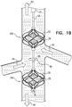
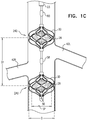
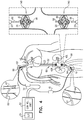
- Figs. 1A-D are schematic illustrations of a blood-pump catheter 20 placed within a subject's vena cava 22, via a guide catheter 23, an upstream pump 24U being disposed upon the catheter, distally to a downstream pump 24D, in accordance with some applications of the present invention.
- the distal portion of blood-pump catheter 20 is configured to be straight, when the catheter is in a non-constrained state, such that both the upstream and the downstream pumps are disposed along the axis of the catheter, within the vena cava.
- Each of the upstream and downstream pumps 24U and 24D typically includes a radially-expandable impeller 28 disposed inside a radially-expandable impeller cage 30.
- impeller 28 and cage 30 are shape set such as to assume radially-expanded configurations thereof in the absence of any radially-constraining force acting upon the impeller and the cage.
- an engagement mechanism engages the impeller and the cage with respect to one another, such that in response to the cage becoming radially constrained the impeller becomes radially constrained, e.g., in accordance with apparatus and methods described in described in WO 14/141284 to Schwammenthal .
- the term "impeller” is used herein to denote a bladed rotor, as shown in 1A-D, for example.
- a blood vessel such as vena cava 22
- the bladed rotor functions as an impeller, by modifying the flow of blood through the blood vessel, and/or by generating a pressure difference between the upstream end and the downstream end of the impeller.
- reference numeral 24 is generally used to denote a blood pump in the present application.
- reference numeral 24U When a pump that is placed upstream is being referred to, reference numeral 24U is used, and when a pump that is placed downstream is being referred to, reference numeral 24D is used.
- reference numeral 28 is generally used to denote an impeller in the present application. When an impeller that is placed upstream is being referred to, reference numeral 28U is used, and when an impeller that is placed downstream is being referred to, reference numeral 28D is used.
- Blood-pump catheter 20 is typically placed inside the subject's vena cava 22, and operated therein, in order to provide acute treatment of a subject suffering from cardiac dysfunction, congestive heart failure, low renal blood flow, high renal vascular resistance, arterial hypertension, diabetes, and/or kidney dysfunction.
- the blood-pump catheter may be placed inside the subject's vena cava, and operated therein, for a period of more than one hour (e.g., more than one day), less than one week (e.g., less than four days), and/or between one hour and one week (e.g., between one day and four days).
- the blood-pump catheter is chronically placed inside the subject's vena cava in order to provide chronic treatment of a subject suffering from cardiac dysfunction, congestive heart failure, low renal blood flow, high renal vascular resistance, arterial hypertension, diabetes, and/or kidney dysfunction.
- a course of treatment is applied to a subject over several weeks, several months, or several years, during which the blood-pump catheter is intermittently placed inside the subject's vena cava, and the subject is intermittently treated in accordance with the techniques described herein.
- the subject may be intermittently treated at intervals of several days, several weeks, or several months.
- blood-pump catheter 20 is inserted into vena cava 22, via the subject's subclavian vein 40, as shown in Fig. 1A .
- the blood-pump catheter is inserted under fluoroscopic imaging.
- the blood-pump catheter is inserted under ultrasound imaging, such as to reduce exposure of the subject to radiation and/or contrast agent.
- the catheter is placed into the vena cava such that upstream pump 24U is disposed upstream of the junctions of the vena cava and all of the subject's renal veins 42, and such that downstream pump 24D is disposed downstream of the junctions of the vena cava and all of the subject's renal veins.
- the upstream pump is configured to pump blood through the vena cava in the upstream direction, away from the renal veins
- the downstream pump is configured to pump blood through the vena cava in the downstream direction, away from the renal veins.
- the effect of both of pumps 24U and 24D pumping blood in the above-described manner is that, between the pumps, and adjacent to the junctions of the vena cava with the renal veins, there is a low-pressure region of the vena cava, within which blood pressure is lower than the subject's central venous pressure. Functionally, this region may be viewed as a compartment within the vena cava within which blood pressure is controlled (by controlling pumps 24U and 24D), regardless of the blood pressure elsewhere within the vena cava. This typically increases blood flow from the renal veins into the vena cava, lowers pressure within the subject's renal veins, and causes renal perfusion to increase.
- the effect of pumps 24U and 24D on blood flow through the renal veins and the vena cava is indicated by arrows 44 in Fig. 1B .
- the effect of operating blood pumps 24U and 24D is that between the pumps there is a low-pressure region of the vena cava.
- the pumps are operated simultaneously such that the pressure within other portions of the vena cava is substantially unchanged relative to when blood-pump catheter 20 is not in operation.
- the pumps are typically operated simultaneously such that the pressure within the vena cava downstream of downstream pump 24D is not substantially increased relative to when blood-pump catheter 20 is not in operation.
- the pumps are typically operated simultaneously such that the pressure within the vena cava upstream of upstream pump 24U is not substantially increased relative to when blood-pump catheter 20 is not in operation.
- the pumps are typically operated simultaneously such that venous return to the vena cava from regions upstream of the upstream pump and downstream from the downstream pump is substantially unchanged relative to when blood-pump catheter 20 is not in operation.
- the pumps the pumps are typically operated simultaneously such as to have a generally synergistic effect on pressure and flow in the region between the pumps, but to have an antagonistic effect on pressure and flow outside of the region, such that, outside of the region, the effects of the two pumps typically substantially cancel each other.
- blood-pump catheter 20 pumps blood in a manner that enhances the rate of flow of blood flow through the renal veins and into the vena cava, but does not cause a substantial change in the direction of the blood flow relative to the natural direction of flow through the renal veins, or from the renal veins to the vena cava (i.e., relative to blood flow in the absence of pumping by the blood-pump catheter). That is to say that the blood-pump catheter pumps blood in the downstream direction through the renal veins and then directly into the portion of the vena cava that is adjacent to the renal veins, rather than, for example, pumping the blood from the renal veins into a different portion of the subject's veins (such as, an upstream location within the vena cava).
- blood-pump catheter 20 enhances blood flow through the renal veins without removing blood from the subject's venous system into a non-venous receptacle, such as an artificial lumen of a blood pump.
- typically blood-pump catheter 20 is placed inside the vena cava of a subject suffering from cardiac dysfunction, congestive heart failure, low renal blood flow, high renal vascular resistance, arterial hypertension, diabetes, and/or kidney dysfunction.
- operating the blood-pump catheter in the vena cava of such a subject causes a lowering and flattening of the subject's renal vein pressure profile, even though the subject's central venous pressure is elevated, e.g., as described with reference to Fig. 4B of WO 14/141284 to Schwammenthal .
- blood-pump catheter 20 performs ultrafiltration on the subject's blood.
- the subject's renal vascular resistance decreases, in accordance with physiological mechanisms that are described, for example, in an article by Haddy et al., entitled “Effect of elevation of intraluminal pressure on renal vascular resistance” (Circulation Research, 1956 ). It is further noted that a treatment of the subject that increases renal perfusion by increasing blood pressure in the subject's renal arteries would typically not effect the aforementioned physiological mechanisms.
- a reduced dosage of diuretics may be administered to the subject relative to a dosage of diuretics that would be administered to the subject in the absence of performing the techniques described herein.
- a regular dosage of diuretics may be administered to the subject, but the diuretics may have a greater effect on the subject, due to the reduction in renal venous pressure.
- ADP atrial natriuretic peptide
- BNP B-type natriuretic peptide
- blood-pump catheter 20 since the subject's central venous pressure is not lowered by using blood-pump catheter 20, it is expected that the subject will continue to release atrial natriuretic peptide (ANP) and B-type natriuretic peptide (BNP), even while the subject's renal venous pressure is reduced by the use of the blood pumps.
- using blood-pump catheter 20 may result in the subject continuing to release atrial natriuretic peptide (ANP) and B-type natriuretic peptide (BNP), as well as resulting in the effectiveness of the aforementioned natural diuretics being greater than the effectiveness of the diuretics in the absence of the use of blood-pump catheter 20.
- each of upstream and downstream pumps 24U and 24D includes an impeller 28, for example, any one of the impellers described in WO 14/141284 to Schwammenthal .
- impeller 28 may have a single blade, two blades (e.g., as described in WO 14/141284 to Schwammenthal ), three blades (e.g., as described in WO 14/141284 to Schwammenthal ), or more than three blades.
- one or both of blood pumps 24U and 24D includes more than one impeller.
- ceteris paribus by using more than one impeller in at least one of the pumps, in order to generate a given flow of blood with the pump, the force that impacts each of the impellers within the pump is smaller than if a single impeller were to be used in the pump.
- one or both of the pumps includes radially-expandable cage 30.
- cage 30 is configured to hold open the inner wall of the vena cava and to separate the inner wall of the vena cava from the impeller, such that the vena cava does not become injured by the impeller.
- impeller 28 and 30 are shape set such as to assume radially-expanded configurations thereof in the absence of any radially-constraining force acting upon the impeller and/or the cage.
- an engagement mechanism engages the impeller and the cage with respect to one another, such that in response to the cage becoming radially constrained the impeller becomes radially constrained, e.g., in accordance with apparatus and methods described in described in WO 14/141284 to Schwammenthal .
- a span SP of impeller 28, when the impeller is in a non-constrained configuration thereof inside the vena cava is more than 14 mm (e.g., more than 16 mm), and/or less than 28 mm (e.g., less than 22 mm), e.g., 14-28 mm, or 16-22 mm.
- a diameter D of cage 30, when the cage is in a non-constrained configuration thereof inside the vena cava is more than 14 mm (e.g., more than 16 mm), and/or less than 40 mm (e.g., less than 35 mm), e.g., 14-40 mm, or 16-35 mm.
- a longitudinal distance D1 between centers of the impellers of the upstream and downstream pumps, measured along the longitudinal axis of the catheter is typically more than 3 cm (e.g., more than 6 cm), and/or less than 18 cm (e.g., less than 14 cm), e.g., 3-18 cm, or 6-14 cm.
- impellers of pumps 24U and 24D are coupled to one or more motors 46 ( Fig. 1A ), which impart rotational motion to the impellers, via one or more shafts, the shaft(s) being housed inside blood-pump catheter 20.
- the motors are disposed outside of the subject's body (as shown), or are placed inside the subject's body (not shown).
- the impellers are rotated in opposite directions from one another, as viewed from an external reference point.
- impellers 28 of upstream and downstream pumps 24U and 24D are rotated in the same rotational direction as one another, as viewed from an external reference point (e.g., in the direction of arrow 48 (i.e., clockwise), or counterclockwise), but the impellers are disposed on the catheter such that the rotation of the impellers in this direction of rotation causes the impellers to pump blood in respective, opposite directions.
- the rotational direction of the impellers "as viewed from an external reference point” should be interpreted to mean the direction of rotational motion of the impellers as observed from any point that is not undergoing the same rotational motion as either of the impellers.
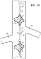
- Fig. 1D shows the impellers in the absence of the cages, although typically, the impellers are used together with cages, as described hereinabove.
- a single motor is used to rotate both of the impellers.
- a shaft 50 is used to impart the rotational motion from the motor to the proximal impeller.
- An additional shaft 51 which is in series with shaft 50, couples the proximal impeller to the distal impeller and imparts the rotational motion from the proximal impeller to the distal impeller.
- the diameter of blood-pump catheter 20 is reduced relative to if parallel shafts were used, in order to impart rotation to the upstream and downstream impellers.
- angles and/or orientations of the impeller blades of impellers 28 of upstream and downstream pumps 24U and 24D may be such as to cause the impellers to pump blood in respective, opposite directions.
- each propeller is shaped and/or oriented in the mirror image of the other, the axis of reflection being orthogonal to the longitudinal axes of the impellers.
- the upstream and downstream impellers are of opposing-handedness to one another, a first one of the impellers being a left-handed impeller, and the other one of the impellers being a right-handed impeller.
- impellers of opposing handedness that are positioned parallel to one another, facing the same direction as one another, and rotating in opposite rotational directions from one another, generate flow in the same direction as one another.
- the upstream and downstream impellers are typically disposed upon shaft 51 such that the impellers are facing in opposite directions to one another.
- the impellers are typically rotated in the same rotational direction as one another, as viewed from an external reference point.
- the result of the impellers (a) being of opposing handedness to one another, and (b) facing in opposite directions, is that, when the impellers are rotated in the same direction as one another about an axis defined by shaft 51, the impellers pump blood in opposite directions from one another.
- the blades of the downstream impeller are oriented such that, as the downstream impeller rotates in the direction of arrow 48, the downstream impeller pumps in the downstream direction.
- the blades of the upstream impeller are oriented such that, as the upstream impeller rotates in the direction of arrow 48, the upstream impeller pumps in the upstream direction.
- upstream and downstream pumps 24U and 24D and blood-pump catheter 20 are placed within a main artery upstream and downstream of bifurcations of the artery with one or more branching arterial systems that branch from the main artery and supply a given organ, mutatis mutandis.
- the blades of the downstream impeller are oriented such that, as the downstream impeller is rotated, the downstream impeller pumps in the upstream direction (toward the bifurcations).
- the blades of the upstream impeller are oriented such that, as the upstream impeller rotates is rotated, the upstream impeller pumps in the downstream direction (toward the bifurcations), such that blood flow into the branching arterial system is increased, thereby increasing perfusion of the organ.
- the blades of the impellers of the upstream and downstream pumps are configured to pump blood in the same direction as one another (e.g., in the antegrade direction).
- the impellers may be of the same handedness as one another, placed upon catheter 20 such that the impellers are facing in the same direction as one another, and rotated in the same direction as one another, as viewed from an external reference point.
- the two impellers may be of opposing handedness to one another, placed within the vena cava such that the two impellers are facing in the same direction as one another, and rotated in opposite directions to one another, as viewed from an external reference point.
- blades of the upstream and downstream impellers are disposed at an angle alpha with respect to the longitudinal axes of the impellers, the blades of the respective impellers being oriented in opposite directions.
- angle alpha is greater than 15 degrees (e.g., greater than 25 degrees), and/or less than 45 degrees (e.g., less than 35 degrees), e.g. 15-45 degrees, or 25-35 degrees.
- impellers 28 of upstream and downstream pumps 24U and 24D are rotated at respective rotation rates, in order to cause the pumping of blood in the upstream and downstream directions to be performed at respective rates.
- the impellers are rotated at the same rotation rate (and, typically, in the same direction), but the impellers are sized, shaped, and/or oriented such that the rate at which blood is pumped, respectively, in the upstream and downstream directions, by the respective impellers, is not equal.
- a control unit 52 and a user interface 54 are disposed outside the subject's body. Further typically, the control unit receives inputs from one or more pressure sensors 56, 58, and/or 60, e.g., as shown in Figs. 1A-D .
- blood-pump catheter 20 includes pressure sensor 58 disposed between the two blood pumps, and is configured to measure pressure within the low-pressure region of the vena cava between the two blood pumps, which is typically indicative of blood pressure within the subject's renal veins, and the blood-pump catheter does not include pressure sensor 56, or pressure sensor 60.
- control unit 52 controls pumps 24U and 24D, e.g., by controlling rotation of impellers 28, responsively to one or more of the above-described inputs.
- user interface 54 displays the subject's current lower-body venous pressure, renal venous pressure, and/or central venous pressure, based upon the signals generated by sensors 56, 58, and/or 60.
- a user based upon the current values of the subject's lower-body venous pressure, renal venous pressure, and/or central venous pressure, a user (such as a healthcare professional) inputs a target value for the subject renal venous pressure, via the user interface.
- control unit 52 controls the speed of the rotation of the impellers, such that the impellers pump blood away from the renal veins at a flow rate that is such as to reduce the renal venous pressure toward the target level, as indicated by the user.
- the control unit stops the impellers rotating.
- the control unit receives an input from an additional sensor (such as a flow sensor and/or an oxygen-saturation sensor, and/or a thermal flow sensor, e.g., as described with reference to Figs. 22Ai-22Cii of WO 14/141284 to Schwammenthal ), and the control unit controls the speed of the rotation of the impellers responsively to an input from the additional sensor.
- control unit 52 typically includes a computer processor that comprises circuitry and that is configured to execute the actions described herein. Typically, the operations described herein that are performed by the computer processor transform the physical state of a memory, which is a real physical article that is in communication with the computer processor, to have a different magnetic polarity, electrical charge, or the like depending on the technology of the memory that is used.
- Control unit 52 is typically a hardware device programmed with computer program instructions to produce a special purpose computer. For example, when programmed to perform the techniques described herein, control unit 52 typically acts as a special purpose renal-venous-pressure-modulating computer processor.
- user interface 54 typically includes any type of user interface configured to receive inputs from a user and/or to provide outputs to the user.
- the user interface may include one or more input devices (such as a keyboard, a mouse, a trackball, a joystick, a touchscreen monitor, a touchpad, a voice-command interface, a smartphone, a tablet computer, and/or other types of input devices that are known in the art), and/or one or more output devices (such as a monitor, an audio output device, a smartphone, a tablet computer, and/or other types of output devices that are known in the art).
- input devices such as a keyboard, a mouse, a trackball, a joystick, a touchscreen monitor, a touchpad, a voice-command interface, a smartphone, a tablet computer, and/or other types of input devices that are known in the art
- output devices such as a monitor, an audio output device, a smartphone, a tablet computer, and/or other types of output devices that are known in the art.
- FIG. 2 is a schematic illustration of blood-pump catheter 20 being inserted into the subject's vena cava 22 via the subject's right jugular vein 62 (through guide catheter 23), in accordance with some applications of the present invention.
- blood-pump catheter 20 is inserted into the vena cava via the subject's right jugular vein, or via another vein that is above the subject's inferior vena cava.
- blood-pump catheter 20 and the functioning thereof are generally as described with reference to Figs. 1A-D .
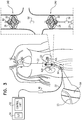
- FIG. 3 is a schematic illustration of blood-pump catheter 20 being inserted into the subject's vena cava 22 via the subject's femoral vein 64 (through guide catheter 23), downstream pump 24D being disposed upon the catheter distally to upstream pump 24U, in accordance with some applications of the present invention.
- blood-pump catheter 20 is inserted into the vena cava, via the subject's femoral vein 64, or via another vein that is below the subject's inferior vena cava.
- downstream blood pump 24D is disposed on blood-pump catheter 20 distally to upstream blood pump 24U.
- Blood-pump catheter 20 is configured to be placed within the vena cava, such that the upstream pump is disposed upstream of the junctions of the vena cava with all of the subject's renal veins 42, and such that the downstream pump is disposed downstream of the junctions of the vena cava with all of the subject's renal veins.
- blood-pump catheter 20 is generally similar to that described with reference to blood-pump catheter 20 as shown in Figs. 1A-D .
- Fig. 4 is a schematic illustration of upstream and downstream pumps 24 U and 24D being disposed on respective catheters 66 and 68, in accordance with some applications of the present invention.
- a first catheter 66 is inserted into vena cava 22 through a guide catheter 67 that is inserted via the subject's femoral vein 64, or via another vein that is below the subject's inferior vena cava.
- Upstream blood pump 24U is disposed on the first catheter, and is configured to be placed within the vena cava upstream of the junctions of the vena cava with all of the subject's renal veins, and to pump blood through the vena cava in the manner described hereinabove.
- a second catheter 68 is inserted into the vena cava through a guide catheter 69 that is inserted via the subject's jugular vein 62 (as shown), via the subclavian vein (not shown), or via a different vein that is above the subject's inferior vena cava.
- Downstream blood pump 24D is disposed on the second catheter, and is configured to be placed within the vena cava downstream of the junctions of the vena cava with all of the subject's renal veins, and to pump blood through the vena cava in the manner described hereinabove.
- control unit 52 controls both pumps (e.g., by controlling the rates of rotation of the impellers).
- pressure sensors 56, 58 and 60 are disposed upon the first and/or second catheters, and are configured to detect indications of, respectively, lower body venous pressure, renal venous pressure, and central venous pressure. The control unit is configured to control the operation of the upstream and downstream pumps responsively to the detected indications, in accordance with the techniques described hereinabove.
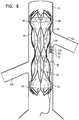
- FIGs. 5A-B are schematic illustrations of blood-pump catheter 20, the catheter including downstream pump 24D and an occlusion element, such as a balloon 80 ( Fig. 5A ), or a covered frame 82 ( Fig. 5B ), in accordance with some applications of the present invention.
- downstream pump is placed inside vena cava 22, downstream of the junctions of the vena cava with all of the subject's renal veins.
- the downstream pump pumps blood through the vena cava, in the downstream direction, away from the junctions of the vena cava with the renal veins, in the manner described hereinabove.
- the occlusion element is placed inside the vena cava upstream of the junctions of the vena cava with the subject's renal veins.
- the occlusion element is configured to partially occlude the subject's vena cava upstream of the junctions of the vena cava with the subject's renal veins.
- the occlusion element is configured to partially occlude the subject's vena cava such that, in response to the pumping of the downstream blood pump, there is not a substantial increase of blood flow from the subject's lower body toward the subject heart, but such that a region of low pressure within the vena cava is generated, between the occlusion element and the downstream blood pump, within which the blood pressure is lower than the subject's central venous pressure.
- a region of low pressure blood flow from the renal veins into the vena cava increases, thereby lowering renal blood pressure and enhancing renal perfusion.
- the occlusion element is configured to partially occlude, but not to totally occlude, the vena cava, in such a manner as to generate a region of low pressure within the vena cava, but to allow a substantial flow of blood through the vena cava
- a longitudinal distance D2 between the longitudinal center of the impeller of the downstream pump and the longitudinal center of the occlusion element, measured along the longitudinal axis of the catheter is typically more than 3 cm (e.g., more than 6 cm), and/or less than 18 cm (e.g., less than 14 cm), e.g., 3-18 cm, or 6-14 cm.
- a "longitudinal axis" of a structure is the set of all centroids of cross-sectional sections of the structure along the structure.
- the cross-sectional sections are locally perpendicular to the longitudinal axis, which runs along the structure.
- the centroids correspond with the centers of the circular cross-sectional sections.
- the term "longitudinal center” denotes the center of a structure along the direction of the structure's longitudinal axis.
- the occlusion element is balloon 80, as shown in Fig. 5A .
- the occlusion element is covered frame 82, as shown in Fig. 5B .
- the frame may be a rigid frame made of a shape-memory element (such as nitinol) that is covered with a blood-impermeable material 83 (e.g., polyester, polyurethane, and/or a different polymer).
- the occlusion element is configured to partially occlude the vena cava upstream of the junctions of the vena cava with the subject's renal veins.
- the diameter to which the occlusion element is expanded is controllable.
- inflation of the balloon may be controllable, or the stent may be expandable (e.g., by heating the stent, or by applying an electrical current to the stent).
- control unit 52 responsively to the blood pressure detected by blood pressure sensor 56, 58, and/or 60, in response to an input from a different sensor (such as a flow sensor and/or an oxygen-saturation sensor, and/or a thermal flow sensor, e.g., as described with reference to Figs. 22Ai-Cii of WO 14/141284 to 2. Schwammenthal), and/or in response to an input from a user.
- a control unit e.g., control unit 52
- a different sensor such as a flow sensor and/or an oxygen-saturation sensor, and/or a thermal flow sensor, e.g., as described with reference to Figs. 22Ai-Cii of WO 14/141284 to 2. Schwammenthal
- the rate at which pump 24D pumps blood away from the renal veins (e.g., the rate at which impeller 28 of the pump is rotated), as well as the extent to which the occlusion element occludes the vena cava is controlled by a control unit responsively to the blood pressure detected by blood pressure sensor 56, 58, and/or 60, in response to an input from a different sensor (such as a flow sensor and/or an oxygen-saturation sensor, and/or a thermal flow sensor, e.g., as described with reference to Figs. 22Ai-Cii of WO 14/141284 to Schwammenthal ), and/or in response to an input from a user.
- a control unit responsively to the blood pressure detected by blood pressure sensor 56, 58, and/or 60, in response to an input from a different sensor (such as a flow sensor and/or an oxygen-saturation sensor, and/or a thermal flow sensor, e.g., as described with reference to Figs. 22Ai
- Figs. 5A and 5B show the downstream blood pump and the occlusion element disposed on a catheter that is inserted into the vena cava from above the junctions of the vena cava with the subject's renal veins (e.g., via the subject's subclavian vein or jugular vein), for some applications, the downstream blood pump and the occlusion element are disposed on a catheter that is inserted into the vena cava from below the junctions of the vena cava with the subject's renal veins (e.g., via the subject's femoral vein), mutatis mutandis.
- the occlusion element is disposed on a first catheter which is inserted into the vena cava from below the junctions of the vena cava with the subject's renal veins (e.g., via the subject's femoral vein), and the downstream blood pump is disposed on a second catheter, which inserted into the vena cava from above the junctions of the vena cava with the subject's renal veins (e.g., via the subject's subclavian vein, or jugular vein).
- FIG. 6 is a schematic illustration of a blood-impermeable sleeve 84 configured to occlude blood flow from a subject's vena cava to the subject's renal veins, as described in WO 14/141284 .
- the sleeve is placed within the vena cava such that a downstream end 86 of the sleeve is coupled to the wall of the vena cava at a first location 88 that is downstream of all renal veins 42 of the subject (e.g., left and right renal vein in a typical subject that has two renal veins), and such that an upstream end 90 of the sleeve is coupled to a wall of the vena cava at a second location 92 that is upstream of all renal veins of the subject.
- the sleeve isolates the blood in the renal veins into a compartment that is separated from blood flow through the center of the vena cava.
- a rigid structure e.g., a stent 94 as shown, is configured to couple the upstream and downstream ends of the sleeve to the vena cava.
- a pump 96 is configured to pump blood through inlet holes 97, from a location that is exterior to sleeve 98 (i.e., from the isolated compartment) to a location that is in fluid communication with the interior of the sleeve (e.g., a location within the vena cava upstream or downstream of the sleeve).
- the pump pumps blood out of the subject's renal veins and into the subject's vena cava.
- the sleeve prevents backflow of blood from the vena cava into the renal veins.
- sleeve 84 and stent 94 are inserted into the subject's vena cava, while a guidewire 99 is disposed inside a pump-accommodating sleeve 95. Subsequent to anchoring sleeve 84 and stent 94 to the vena cava, pump 96 is inserted through the pump-accommodating sleeve, by advancing the pump over the guidewire.
- Sleeve 84 and pump 96 are generally as described with reference to Figs. 10A-D of WO 14/141284 to Schwammenthal .
- a low-pressure region is generated within the subject's vena cava, adjacent to junctions of the vena cava with the subject's renal veins, blood pressure within the low-pressure region being lower than central venous pressure of the subject.
- a low-pressure region is generated within the subject's vena cava, adjacent to junctions of the vena cava with the subject's renal veins, blood pressure within the low-pressure region being lower than central venous pressure of the subject.
- the effect of generating the low-pressure region within the vena cava is typically that blood flow from the renal veins to the vena cava is increased, thereby reducing renal venous pressure, and increasing renal perfusion.
- proximal and related terms when used with reference to a device or a portion thereof, should be interpreted to mean an end of the device or the portion thereof that, when inserted into a subject's body, is typically closer to a location through which the device is inserted into the subject's body.
- distal when used with reference to a device or a portion thereof, should be interpreted to mean an end of the device or the portion thereof that, when inserted into a subject's body, is typically further from the location through which the device is inserted into the subject's body.
- downstream and related terms when used with reference to a blood vessel, or with reference to a portion of a device that is configured to be placed inside a blood vessel, should be interpreted to mean a location within the blood vessel, or a portion of the device that is intended for placement at a location within the blood vessel, that is downstream, with respect to the direction of antegrade blood flow through the blood vessel, relative to a different location within the blood vessel.
- upstream when used with reference to a blood vessel, or with reference to a portion of a device that is configured to be placed inside a blood vessel, should be interpreted to mean a location within the blood vessel, or a portion of the device that is intended for placement at a location within the blood vessel, that is upstream with respect to the direction of antegrade blood flow through the blood vessel, relative to a different location within the blood vessel.
- blood pumps 24U and 24D the catheters upon which the blood pumps are disposed (e.g., blood-pump catheter 20, catheter 66, and catheter 68), and the occlusion elements described with reference to Figs. 5A-B , and other devices described herein, are generally described as being placed within the subject's vena cava, such that the upstream pump or the occlusion element is disposed upstream of junctions of the vena cava with the subject's renal veins, and the downstream pump is disposed downstream of the junctions of the vena cava with the subject's renal veins.
- the scope of the present invention includes placing upstream pump 24U or the occlusion element in any main vein upstream of a tributary venous system, and placing downstream pump 24D downstream of said tributary venous system, and configuring the pump(s) (e.g., via the direction of rotation of impellers of the pumps, or the orientation of the pumps) to generate preferential flow from the tributaries into the main vein, mutatis mutandis.
- the pump(s) could be used to generate flow from the subject's hepatic veins into the subject's vena cava, in order to increase perfusion of the subject's liver, mutatis mutandis.
- the upstream pump or the occlusion element is placed within a main vein upstream of two or more tributary venous systems into the main vein (e.g., within the vena cava upstream of the renal venous system and the hepatic venous system).
- the downstream pump is placed downstream of the two or more tributary venous systems.
- the pump(s) are configured to generate preferential flow from both of the tributary venous systems into the main vein by pumping blood through the main vein, in the manner described herein.
- upstream pump 24U or the occlusion element is placed in a main vein upstream of a tributary venous system
- downstream pump 24D is placed downstream of said tributary venous system
- the pump(s) are configured (e.g., via the direction of rotation of impellers of the pumps, or the orientation of the pumps) to reduce flow from the tributaries into the main vein.
- the blades of the downstream impeller are oriented such that, as the downstream impeller is rotated, the downstream impeller pumps in the upstream direction (toward the junction between the tributary system and the main vein).
- the blades of the upstream impeller are oriented such that, as the upstream impeller rotates is rotated, the upstream impeller pumps in the downstream direction (toward the junction between the tributary system and the main vein).
- the upstream and downstream pumps 24U and 24D, the catheter(s) upon which the blood pumps are disposed e.g., blood-pump catheter 20, catheter 66, and catheter 68
- the occlusion elements described with reference to Figs. 5A-B , and other devices described herein are placed within a main artery upstream and downstream of bifurcations of the artery with one or more branching arterial systems that branch from the main artery and supply a given organ, mutatis mutandis.
- the upstream pump is typically configured to pump in the downstream direction (toward the bifurcations) and the downstream pump is configured to pump in the upstream direction (toward the bifurcations), such that blood flow into the branching arterial system is increased, thereby increasing perfusion of the organ.
- the occlusion element is placed downstream of the bifurcations of the artery with the one or more arterial systems and is configured to partially occlude the artery downstream of the bifurcations.
- the upstream pump may be placed in the subject's aorta upstream of the subject's renal arteries and the downstream pump may be placed in the subject's aorta downstream of the subject's renal arteries, the pumps acting to pump blood into the renal arteries and toward the subject's kidneys.
- upstream and downstream pumps, and/or occlusion elements are placed on both the arterial and venous sides of the subject's body in order to increase perfusion of a given organ or set of organs, in the manner described herein.
- the scope of the present invention includes using any other type of pump for pumping blood in the manner described herein, mutatis mutandis.
- a roller pump an Archimedes screw pump, a centrifugal pump, a pneumatic pump, and/or a compression pump may be used.
Landscapes
- Health & Medical Sciences (AREA)
- Engineering & Computer Science (AREA)
- Heart & Thoracic Surgery (AREA)
- Cardiology (AREA)
- Life Sciences & Earth Sciences (AREA)
- Public Health (AREA)
- Biomedical Technology (AREA)
- Hematology (AREA)
- Mechanical Engineering (AREA)
- Animal Behavior & Ethology (AREA)
- General Health & Medical Sciences (AREA)
- Anesthesiology (AREA)
- Veterinary Medicine (AREA)
- Vascular Medicine (AREA)
- Urology & Nephrology (AREA)
- Physics & Mathematics (AREA)
- Optics & Photonics (AREA)
- External Artificial Organs (AREA)
Claims (14)
- Vorrichtung, die Folgendes umfasst:einen Katheter (20), der dafür konfiguriert ist, innerhalb eines Blutgefäßes eines Subjekts platziert zu werden,eine Blutpumpe (24D), die an dem Katheter (20) angeordnet ist, undein Verschlusselement (80, 82), das an dem Katheter (20) angeordnet und dafür konfiguriert ist, das Blutgefäß des Subjekts teilweise zu verschließen,wobei Längsmitten der Blutpumpe (24D) und des Verschlusselements (80, 82) durch einen Abstand von mindestens 3 cm voneinander getrennt sind, wobei der Abstand entlang einer Längsachse des Katheters (20) gemessen wird,dadurch gekennzeichnet, dass:
die Blutpumpe (24D) und das Verschlusselement (80, 82) dafür konfiguriert sind, dadurch, dass die Blutpumpe (24D) von einem Bereich des Blutgefäßes zwischen der Blutpumpe (24D) und dem Verschlusselement (80, 82) weg in einer Richtung stromabwärts pumpt, einen Bereich innerhalb des Blutgefäßes zu erzeugen, der einen niedrigeren Blutdruck als an anderer Stelle innerhalb des Blutgefäßes aufweist. - Vorrichtung nach Anspruch 1, wobei die Blutpumpe (24D) ein Laufrad (28) umfasst, das dafür konfiguriert ist, durch Drehen Blut durch das Blutgefäß des Subjekts zu pumpen.
- Vorrichtung nach Anspruch 2, die ferner einen Käfig (30) umfasst, wobei das Laufrad (28) innerhalb des Käfigs (30) angeordnet ist und der Käfig (30) dafür konfiguriert ist, eine Trennung zwischen dem Laufrad (28) und einer inneren Wand des Blutgefäßes aufrechtzuerhalten.
- Vorrichtung nach Anspruch 1, wobei der Katheter (20) dafür konfiguriert ist, derart innerhalb einer Hohlvene eines Subjekts angeordnet zu werden, dass die Blutpumpe (24D) stromabwärts von Verbindungen der Hohlvene mit allen Nierenvenen des Subjekts angeordnet ist, und derart, dass das Verschlusselement (80, 82) stromaufwärts von Verbindungen der Hohlvene mit allen Nierenvenen des Subjekts angeordnet ist.
- Vorrichtung nach Anspruch 4, wobei die Blutpumpe (24D) dafür konfiguriert ist, durch Pumpen von Blut durch die Hohlvene in einer Richtung stromabwärts den Druck innerhalb der Nierenvenen des Subjekts abzusenken.
- Vorrichtung nach Anspruch 4, wobei der Katheter (20) dafür konfiguriert ist, dadurch innerhalb der Hohlvene des Subjekts platziert zu werden, dass er über eine Vene des Subjekts eingesetzt wird, die aus der Gruppe ausgewählt ist, die aus einer Schlüsselbeinvene, einer Drosselvene und einer Oberschenkelvene besteht.
- Vorrichtung nach Anspruch 4, wobei die Blutpumpe (24D) ein Laufrad (28) umfasst, das dafür konfiguriert ist, durch Drehen Blut durch die Hohlvene zu pumpen.
- Vorrichtung nach Anspruch 7, die ferner einen Käfig (30) umfasst, wobei das Laufrad (28) innerhalb des Käfigs (30) angeordnet ist und der Käfig (30) dafür konfiguriert ist, eine Trennung zwischen dem Laufrad (28) und einer inneren Wand der Hohlvene aufrechtzuerhalten.
- Vorrichtung nach Anspruch 1, wobei das Verschlusselement (80, 82) dafür konfiguriert ist, die Hohlvene des Subjekts derart teilweise zu verschließen, dass es, in Reaktion auf das Pumpen der Blutpumpe (24D) in der Richtung stromabwärts, keine wesentliche Zunahme eines Blutflusses von einem Unterkörper des Subjekts hin zu einem Herzen des Subjekts gibt, aber derart, dass innerhalb der Hohlvene, zwischen dem Verschlusselement und der Stromabwärts-Blutpumpe, ein Bereich mit niedrigem Druck erzeugt wird, innerhalb dessen der Blutdruck niedriger ist als der zentrale Venendruck des Subjekts.
- Vorrichtung nach Anspruch 1, wobei der Katheter (20) dafür konfiguriert ist, derart innerhalb einer Hauptvene eines Subjekts, in die Blut aus einem sekundär Venensystem fließt, angeordnet zu werden, dass:die Blutpumpe (24D) in der Hauptvene, stromabwärts von dem zufließenden Venensystem, platziert ist, unddas Verschlusselement (80, 82) in der Hauptvene, stromaufwärts von dem zufließenden Venensystem, platziert ist.
- Vorrichtung nach Anspruch 1, wobei das Verschlusselement (80, 82) einen Ballon umfasst.
- Vorrichtung nach Anspruch 1, wobei das Verschlusselement (80, 82) einen Rahmen umfasst, der mit einem blutundurchlässigen Material bedeckt ist.
- Vorrichtung nach Anspruch 1, die ferner eine Steuereinheit umfasst, die dafür konfiguriert ist, einen Durchmesser zu steuern, bis zu dem das Verschlusselement (80, 82) ausgedehnt wird.
- Vorrichtung nach Anspruch 1, wobei das Verschlusselement (80, 82) dafür konfiguriert ist, das Blutgefäß auf eine solche Weise teilweise zu verschließen, aber nicht vollständig zu verschließen, dass ein Bereich mit niedrigem Druck innerhalb des Bereichs des Blutgefäßes zwischen der Blutpumpe (24D) und dem Verschlusselement (80, 82) erzeugt wird, aber ein wesentlicher Blutfluss durch das Blutgefäß zugelassen wird.
Priority Applications (1)
| Application Number | Priority Date | Filing Date | Title |
|---|---|---|---|
| EP20179137.3A EP3744362B1 (de) | 2014-05-19 | 2015-05-19 | Blutpumpe |
Applications Claiming Priority (2)
| Application Number | Priority Date | Filing Date | Title |
|---|---|---|---|
| US201462000192P | 2014-05-19 | 2014-05-19 | |
| PCT/IL2015/050532 WO2015177793A2 (en) | 2014-05-19 | 2015-05-19 | Blood pump |
Related Child Applications (2)
| Application Number | Title | Priority Date | Filing Date |
|---|---|---|---|
| EP20179137.3A Division EP3744362B1 (de) | 2014-05-19 | 2015-05-19 | Blutpumpe |
| EP20179137.3A Division-Into EP3744362B1 (de) | 2014-05-19 | 2015-05-19 | Blutpumpe |
Publications (2)
| Publication Number | Publication Date |
|---|---|
| EP3145559A2 EP3145559A2 (de) | 2017-03-29 |
| EP3145559B1 true EP3145559B1 (de) | 2020-08-05 |
Family
ID=53900886
Family Applications (2)
| Application Number | Title | Priority Date | Filing Date |
|---|---|---|---|
| EP15753493.4A Active EP3145559B1 (de) | 2014-05-19 | 2015-05-19 | Blutpumpe |
| EP20179137.3A Active EP3744362B1 (de) | 2014-05-19 | 2015-05-19 | Blutpumpe |
Family Applications After (1)
| Application Number | Title | Priority Date | Filing Date |
|---|---|---|---|
| EP20179137.3A Active EP3744362B1 (de) | 2014-05-19 | 2015-05-19 | Blutpumpe |
Country Status (6)
| Country | Link |
|---|---|
| EP (2) | EP3145559B1 (de) |
| JP (2) | JP6652933B2 (de) |
| CN (2) | CN109381756B (de) |
| AU (1) | AU2015262870B2 (de) |
| CA (2) | CA3192217A1 (de) |
| WO (1) | WO2015177793A2 (de) |
Cited By (2)
| Publication number | Priority date | Publication date | Assignee | Title |
|---|---|---|---|---|
| US11883030B2 (en) | 2022-04-29 | 2024-01-30 | inQB8 Medical Technologies, LLC | Systems, devices, and methods for controllably and selectively occluding, restricting, and diverting flow within a patient's vasculature |
| US11974751B2 (en) | 2022-04-29 | 2024-05-07 | inQB8 Medical Technologies, LLC | Systems, devices, and methods for controllably and selectively occluding, restricting, and diverting flow within a patient's vasculature |
Families Citing this family (39)
| Publication number | Priority date | Publication date | Assignee | Title |
|---|---|---|---|---|
| CN108742951B (zh) | 2012-06-06 | 2021-05-25 | 洋红医疗有限公司 | 人工肾脏瓣膜 |
| US10583231B2 (en) | 2013-03-13 | 2020-03-10 | Magenta Medical Ltd. | Blood pump |
| CN105473063B (zh) | 2013-03-13 | 2019-03-08 | 马真塔医药有限公司 | 血液泵浦及其制造方法 |
| US11291824B2 (en) | 2015-05-18 | 2022-04-05 | Magenta Medical Ltd. | Blood pump |
| EP3518825B1 (de) | 2016-09-29 | 2020-05-27 | Magenta Medical Ltd. | Blutgefässtubus |
| EP3532120B1 (de) | 2016-10-25 | 2024-05-01 | Magenta Medical Ltd. | Ventrikelunterstützungsvorrichtung |
| JP7094279B2 (ja) | 2016-11-23 | 2022-07-01 | マジェンタ・メディカル・リミテッド | 血液ポンプ |
| DE102017102823A1 (de) * | 2017-02-13 | 2018-08-16 | Cardiobridge Gmbh | Katheterpumpe mit einem Pumpenkopf zum Einsetzen in das arterielle Gefäßsystem |
| EP3630007A1 (de) | 2017-06-02 | 2020-04-08 | Nephronyx Ltd. | Strömungsmodifikation in körperlumen |
| CA3066361A1 (en) * | 2017-06-07 | 2018-12-13 | Shifamed Holdings, Llc | Intravascular fluid movement devices, systems, and methods of use |
| EP3710076B1 (de) | 2017-11-13 | 2023-12-27 | Shifamed Holdings, LLC | Intravaskuläre fluidbewegungsvorrichtungen, systeme und verwendungsverfahren |
| US10905808B2 (en) | 2018-01-10 | 2021-02-02 | Magenta Medical Ltd. | Drive cable for use with a blood pump |
| EP3693038B1 (de) | 2018-01-10 | 2024-06-05 | Magenta Medical Ltd. | Ventrikelunterstützungsvorrichtung |
| DE102018201030A1 (de) | 2018-01-24 | 2019-07-25 | Kardion Gmbh | Magnetkuppelelement mit magnetischer Lagerungsfunktion |
| US11596783B2 (en) | 2018-03-06 | 2023-03-07 | Indiana University Research & Technology Corporation | Blood pressure powered auxiliary pump |
| US10893927B2 (en) | 2018-03-29 | 2021-01-19 | Magenta Medical Ltd. | Inferior vena cava blood-flow implant |
| WO2019195480A1 (en) * | 2018-04-04 | 2019-10-10 | Theodosios Korakianitis | Removable mechanical circulatory support for short term use |
| US11690997B2 (en) | 2018-04-06 | 2023-07-04 | Puzzle Medical Devices Inc. | Mammalian body conduit intralumenal device and lumen wall anchor assembly, components thereof and methods of implantation and explanation thereof |
| US11298519B2 (en) | 2018-05-08 | 2022-04-12 | Abiomed, Inc. | Use of cardiac assist device to improve kidney function |
| DE102018211327A1 (de) | 2018-07-10 | 2020-01-16 | Kardion Gmbh | Laufrad für ein implantierbares, vaskuläres Unterstützungssystem |
| CN113597291A (zh) * | 2018-11-26 | 2021-11-02 | 内弗罗尼公司 | 体腔中的流动调节装置 |
| EP3782665B1 (de) | 2019-01-24 | 2021-08-25 | Magenta Medical Ltd. | Ventrikelunterstützungsvorrichtung |
| EP3698820A1 (de) * | 2019-02-22 | 2020-08-26 | ECP Entwicklungsgesellschaft mbH | Kathetervorrichtung mit einer antriebswellenabdeckung |
| WO2020234785A1 (en) | 2019-05-23 | 2020-11-26 | Magenta Medical Ltd | Blood pumps |
| EP3990095A4 (de) | 2019-06-28 | 2023-07-12 | Theodosios Alexander | Abnehmbarer mechanischer kreislaufunterstützer für kurzzeitgebrauch |
| JP2022540616A (ja) | 2019-07-12 | 2022-09-16 | シファメド・ホールディングス・エルエルシー | 血管内血液ポンプならびに製造および使用の方法 |
| US11654275B2 (en) | 2019-07-22 | 2023-05-23 | Shifamed Holdings, Llc | Intravascular blood pumps with struts and methods of use and manufacture |
| US11724089B2 (en) | 2019-09-25 | 2023-08-15 | Shifamed Holdings, Llc | Intravascular blood pump systems and methods of use and control thereof |
| DE102020102474A1 (de) | 2020-01-31 | 2021-08-05 | Kardion Gmbh | Pumpe zum Fördern eines Fluids und Verfahren zum Herstellen einer Pumpe |
| JP7467668B2 (ja) | 2020-03-25 | 2024-04-15 | ボストン サイエンティフィック サイムド,インコーポレイテッド | 非代償性心不全を治療するための医療デバイス |
| WO2021198881A1 (en) | 2020-04-02 | 2021-10-07 | Magenta Medical Ltd | Centrifugal and mixed-flow impellers for use with a blood pump |
| CA3176272A1 (en) | 2020-04-07 | 2021-10-14 | Magenta Medical Ltd | Ventricular assist device |
| US11395910B2 (en) | 2020-05-20 | 2022-07-26 | Rainbow Medical Ltd. | Passive pump |
| EP4157144A4 (de) | 2020-05-28 | 2024-06-05 | Nephronyx Ltd | Akute und chronische vorrichtungen zur modifizierung des flusses in körperlumen und verfahren zur verwendung davon |
| CN116549834A (zh) | 2021-03-09 | 2023-08-08 | 马真塔医药有限公司 | 心室辅助装置 |
| CA3232768A1 (en) | 2021-10-11 | 2023-04-20 | Magenta Medical Ltd | Ventricular assist device |
| US11484700B1 (en) | 2021-10-25 | 2022-11-01 | Yossi Gross | Mechanical treatment of heart failure |
| US11357629B1 (en) | 2021-10-25 | 2022-06-14 | Rainbow Medical Ltd. | Diastolic heart failure treatment |
| WO2024057253A2 (en) | 2022-09-14 | 2024-03-21 | Magenta Medical Ltd | Delivery tube |
Citations (3)
| Publication number | Priority date | Publication date | Assignee | Title |
|---|---|---|---|---|
| WO2001083016A2 (en) * | 2000-05-01 | 2001-11-08 | Flowmedica, Inc. | Apparatus and methods for treating congestive heart disease |
| US20070208291A1 (en) * | 2006-03-02 | 2007-09-06 | Vinod Patel | Method and Apparatus for Treatment of Congestive Heart Disease |
| WO2008005747A2 (en) * | 2006-06-30 | 2008-01-10 | Moreschi Rafael M | Trans-septal heart assist devices and methods of use |
Family Cites Families (11)
| Publication number | Priority date | Publication date | Assignee | Title |
|---|---|---|---|---|
| DE19613565C1 (de) * | 1996-04-04 | 1997-07-24 | Guenter Prof Dr Rau | Intravasale Blutpumpe |
| IL118352A0 (en) * | 1996-05-21 | 1996-09-12 | Sudai Amnon | Apparatus and methods for revascularization |
| GB9616267D0 (en) * | 1996-08-02 | 1996-09-11 | Ranier Ltd | Balloon catheter |
| WO2005020848A2 (en) * | 2003-08-28 | 2005-03-10 | Advanced Research And Technology Institute, Inc. | Cavopulmonary assist device and associated method |
| US8419609B2 (en) * | 2005-10-05 | 2013-04-16 | Heartware Inc. | Impeller for a rotary ventricular assist device |
| AU2013205145B2 (en) * | 2005-10-05 | 2013-08-15 | Heartware, Inc. | Axial flow pump with multi-grooved rotor |
| US9277995B2 (en) * | 2010-01-29 | 2016-03-08 | Corvia Medical, Inc. | Devices and methods for reducing venous pressure |
| WO2011112463A1 (en) * | 2010-03-06 | 2011-09-15 | Fulton Richard Eustis Iii | Recovery catheter assembly |
| WO2013148697A1 (en) * | 2012-03-26 | 2013-10-03 | Procyrion, Inc. | Systems and methods for fluid flows and/or pressures for circulation and perfusion enhancement |
| CN108742951B (zh) | 2012-06-06 | 2021-05-25 | 洋红医疗有限公司 | 人工肾脏瓣膜 |
| CN105473063B (zh) | 2013-03-13 | 2019-03-08 | 马真塔医药有限公司 | 血液泵浦及其制造方法 |
-
2015
- 2015-05-19 CA CA3192217A patent/CA3192217A1/en active Pending
- 2015-05-19 CA CA2948121A patent/CA2948121C/en active Active
- 2015-05-19 EP EP15753493.4A patent/EP3145559B1/de active Active
- 2015-05-19 WO PCT/IL2015/050532 patent/WO2015177793A2/en active Application Filing
- 2015-05-19 CN CN201811196500.1A patent/CN109381756B/zh active Active
- 2015-05-19 CN CN201580031545.1A patent/CN106456857B/zh active Active
- 2015-05-19 EP EP20179137.3A patent/EP3744362B1/de active Active
- 2015-05-19 AU AU2015262870A patent/AU2015262870B2/en active Active
- 2015-05-19 JP JP2016568548A patent/JP6652933B2/ja active Active
-
2020
- 2020-01-23 JP JP2020009045A patent/JP6974514B2/ja active Active
Patent Citations (3)
| Publication number | Priority date | Publication date | Assignee | Title |
|---|---|---|---|---|
| WO2001083016A2 (en) * | 2000-05-01 | 2001-11-08 | Flowmedica, Inc. | Apparatus and methods for treating congestive heart disease |
| US20070208291A1 (en) * | 2006-03-02 | 2007-09-06 | Vinod Patel | Method and Apparatus for Treatment of Congestive Heart Disease |
| WO2008005747A2 (en) * | 2006-06-30 | 2008-01-10 | Moreschi Rafael M | Trans-septal heart assist devices and methods of use |
Cited By (2)
| Publication number | Priority date | Publication date | Assignee | Title |
|---|---|---|---|---|
| US11883030B2 (en) | 2022-04-29 | 2024-01-30 | inQB8 Medical Technologies, LLC | Systems, devices, and methods for controllably and selectively occluding, restricting, and diverting flow within a patient's vasculature |
| US11974751B2 (en) | 2022-04-29 | 2024-05-07 | inQB8 Medical Technologies, LLC | Systems, devices, and methods for controllably and selectively occluding, restricting, and diverting flow within a patient's vasculature |
Also Published As
| Publication number | Publication date |
|---|---|
| EP3145559A2 (de) | 2017-03-29 |
| CA2948121C (en) | 2023-05-02 |
| CA2948121A1 (en) | 2015-11-26 |
| JP6652933B2 (ja) | 2020-02-26 |
| WO2015177793A3 (en) | 2016-03-17 |
| JP2017515607A (ja) | 2017-06-15 |
| EP3744362B1 (de) | 2023-11-15 |
| EP3744362C0 (de) | 2023-11-15 |
| EP3744362A1 (de) | 2020-12-02 |
| AU2015262870B2 (en) | 2019-10-10 |
| JP2020072985A (ja) | 2020-05-14 |
| CA3192217A1 (en) | 2015-11-26 |
| JP6974514B2 (ja) | 2021-12-01 |
| CN109381756B (zh) | 2021-08-17 |
| AU2015262870A1 (en) | 2016-11-17 |
| CN106456857B (zh) | 2018-11-02 |
| CN109381756A (zh) | 2019-02-26 |
| WO2015177793A8 (en) | 2016-05-19 |
| WO2015177793A2 (en) | 2015-11-26 |
| CN106456857A (zh) | 2017-02-22 |
Similar Documents
| Publication | Publication Date | Title |
|---|---|---|
| US11648391B2 (en) | Blood pump | |
| EP3145559B1 (de) | Blutpumpe | |
| US20240157116A1 (en) | Blood pump | |
| US11648392B2 (en) | Blood pumps | |
| AU2021225141B2 (en) | Renal pump | |
| US20220218976A1 (en) | Blood pumps |
Legal Events
| Date | Code | Title | Description |
|---|---|---|---|
| STAA | Information on the status of an ep patent application or granted ep patent |
Free format text: STATUS: THE INTERNATIONAL PUBLICATION HAS BEEN MADE |
|
| PUAI | Public reference made under article 153(3) epc to a published international application that has entered the european phase |
Free format text: ORIGINAL CODE: 0009012 |
|
| STAA | Information on the status of an ep patent application or granted ep patent |
Free format text: STATUS: REQUEST FOR EXAMINATION WAS MADE |
|
| 17P | Request for examination filed |
Effective date: 20161118 |
|
| AK | Designated contracting states |
Kind code of ref document: A2 Designated state(s): AL AT BE BG CH CY CZ DE DK EE ES FI FR GB GR HR HU IE IS IT LI LT LU LV MC MK MT NL NO PL PT RO RS SE SI SK SM TR |
|
| AX | Request for extension of the european patent |
Extension state: BA ME |
|
| DAV | Request for validation of the european patent (deleted) | ||
| DAX | Request for extension of the european patent (deleted) | ||
| STAA | Information on the status of an ep patent application or granted ep patent |
Free format text: STATUS: EXAMINATION IS IN PROGRESS |
|
| PUAG | Search results despatched under rule 164(2) epc together with communication from examining division |
Free format text: ORIGINAL CODE: 0009017 |
|
| 17Q | First examination report despatched |
Effective date: 20190717 |
|
| B565 | Issuance of search results under rule 164(2) epc |
Effective date: 20190717 |
|
| RIC1 | Information provided on ipc code assigned before grant |
Ipc: A61M 1/10 20060101AFI20190712BHEP Ipc: A61M 1/12 20060101ALI20190712BHEP |
|
| GRAP | Despatch of communication of intention to grant a patent |
Free format text: ORIGINAL CODE: EPIDOSNIGR1 |
|
| STAA | Information on the status of an ep patent application or granted ep patent |
Free format text: STATUS: GRANT OF PATENT IS INTENDED |
|
| INTG | Intention to grant announced |
Effective date: 20200214 |
|
| GRAS | Grant fee paid |
Free format text: ORIGINAL CODE: EPIDOSNIGR3 |
|
| GRAA | (expected) grant |
Free format text: ORIGINAL CODE: 0009210 |
|
| STAA | Information on the status of an ep patent application or granted ep patent |
Free format text: STATUS: THE PATENT HAS BEEN GRANTED |
|
| AK | Designated contracting states |
Kind code of ref document: B1 Designated state(s): AL AT BE BG CH CY CZ DE DK EE ES FI FR GB GR HR HU IE IS IT LI LT LU LV MC MK MT NL NO PL PT RO RS SE SI SK SM TR |
|
| REG | Reference to a national code |
Ref country code: GB Ref legal event code: FG4D |
|
| REG | Reference to a national code |
Ref country code: CH Ref legal event code: EP |
|
| REG | Reference to a national code |
Ref country code: AT Ref legal event code: REF Ref document number: 1297811 Country of ref document: AT Kind code of ref document: T Effective date: 20200815 |
|
| REG | Reference to a national code |
Ref country code: DE Ref legal event code: R096 Ref document number: 602015056954 Country of ref document: DE |
|
| REG | Reference to a national code |
Ref country code: NL Ref legal event code: FP Ref country code: IE Ref legal event code: FG4D |
|
| REG | Reference to a national code |
Ref country code: DE Ref legal event code: R079 Ref document number: 602015056954 Country of ref document: DE Free format text: PREVIOUS MAIN CLASS: A61M0001100000 Ipc: A61M0060000000 |
|
| REG | Reference to a national code |
Ref country code: LT Ref legal event code: MG4D |
|
| REG | Reference to a national code |
Ref country code: AT Ref legal event code: MK05 Ref document number: 1297811 Country of ref document: AT Kind code of ref document: T Effective date: 20200805 |
|
| PG25 | Lapsed in a contracting state [announced via postgrant information from national office to epo] |
Ref country code: FI Free format text: LAPSE BECAUSE OF FAILURE TO SUBMIT A TRANSLATION OF THE DESCRIPTION OR TO PAY THE FEE WITHIN THE PRESCRIBED TIME-LIMIT Effective date: 20200805 Ref country code: SE Free format text: LAPSE BECAUSE OF FAILURE TO SUBMIT A TRANSLATION OF THE DESCRIPTION OR TO PAY THE FEE WITHIN THE PRESCRIBED TIME-LIMIT Effective date: 20200805 Ref country code: AT Free format text: LAPSE BECAUSE OF FAILURE TO SUBMIT A TRANSLATION OF THE DESCRIPTION OR TO PAY THE FEE WITHIN THE PRESCRIBED TIME-LIMIT Effective date: 20200805 Ref country code: GR Free format text: LAPSE BECAUSE OF FAILURE TO SUBMIT A TRANSLATION OF THE DESCRIPTION OR TO PAY THE FEE WITHIN THE PRESCRIBED TIME-LIMIT Effective date: 20201106 Ref country code: HR Free format text: LAPSE BECAUSE OF FAILURE TO SUBMIT A TRANSLATION OF THE DESCRIPTION OR TO PAY THE FEE WITHIN THE PRESCRIBED TIME-LIMIT Effective date: 20200805 Ref country code: PT Free format text: LAPSE BECAUSE OF FAILURE TO SUBMIT A TRANSLATION OF THE DESCRIPTION OR TO PAY THE FEE WITHIN THE PRESCRIBED TIME-LIMIT Effective date: 20201207 Ref country code: NO Free format text: LAPSE BECAUSE OF FAILURE TO SUBMIT A TRANSLATION OF THE DESCRIPTION OR TO PAY THE FEE WITHIN THE PRESCRIBED TIME-LIMIT Effective date: 20201105 Ref country code: LT Free format text: LAPSE BECAUSE OF FAILURE TO SUBMIT A TRANSLATION OF THE DESCRIPTION OR TO PAY THE FEE WITHIN THE PRESCRIBED TIME-LIMIT Effective date: 20200805 Ref country code: ES Free format text: LAPSE BECAUSE OF FAILURE TO SUBMIT A TRANSLATION OF THE DESCRIPTION OR TO PAY THE FEE WITHIN THE PRESCRIBED TIME-LIMIT Effective date: 20200805 Ref country code: BG Free format text: LAPSE BECAUSE OF FAILURE TO SUBMIT A TRANSLATION OF THE DESCRIPTION OR TO PAY THE FEE WITHIN THE PRESCRIBED TIME-LIMIT Effective date: 20201105 |
|
| PG25 | Lapsed in a contracting state [announced via postgrant information from national office to epo] |
Ref country code: PL Free format text: LAPSE BECAUSE OF FAILURE TO SUBMIT A TRANSLATION OF THE DESCRIPTION OR TO PAY THE FEE WITHIN THE PRESCRIBED TIME-LIMIT Effective date: 20200805 Ref country code: LV Free format text: LAPSE BECAUSE OF FAILURE TO SUBMIT A TRANSLATION OF THE DESCRIPTION OR TO PAY THE FEE WITHIN THE PRESCRIBED TIME-LIMIT Effective date: 20200805 Ref country code: RS Free format text: LAPSE BECAUSE OF FAILURE TO SUBMIT A TRANSLATION OF THE DESCRIPTION OR TO PAY THE FEE WITHIN THE PRESCRIBED TIME-LIMIT Effective date: 20200805 Ref country code: IS Free format text: LAPSE BECAUSE OF FAILURE TO SUBMIT A TRANSLATION OF THE DESCRIPTION OR TO PAY THE FEE WITHIN THE PRESCRIBED TIME-LIMIT Effective date: 20201205 |
|
| PG25 | Lapsed in a contracting state [announced via postgrant information from national office to epo] |
Ref country code: CZ Free format text: LAPSE BECAUSE OF FAILURE TO SUBMIT A TRANSLATION OF THE DESCRIPTION OR TO PAY THE FEE WITHIN THE PRESCRIBED TIME-LIMIT Effective date: 20200805 Ref country code: DK Free format text: LAPSE BECAUSE OF FAILURE TO SUBMIT A TRANSLATION OF THE DESCRIPTION OR TO PAY THE FEE WITHIN THE PRESCRIBED TIME-LIMIT Effective date: 20200805 Ref country code: SM Free format text: LAPSE BECAUSE OF FAILURE TO SUBMIT A TRANSLATION OF THE DESCRIPTION OR TO PAY THE FEE WITHIN THE PRESCRIBED TIME-LIMIT Effective date: 20200805 Ref country code: RO Free format text: LAPSE BECAUSE OF FAILURE TO SUBMIT A TRANSLATION OF THE DESCRIPTION OR TO PAY THE FEE WITHIN THE PRESCRIBED TIME-LIMIT Effective date: 20200805 Ref country code: EE Free format text: LAPSE BECAUSE OF FAILURE TO SUBMIT A TRANSLATION OF THE DESCRIPTION OR TO PAY THE FEE WITHIN THE PRESCRIBED TIME-LIMIT Effective date: 20200805 |
|
| REG | Reference to a national code |
Ref country code: DE Ref legal event code: R097 Ref document number: 602015056954 Country of ref document: DE |
|
| PG25 | Lapsed in a contracting state [announced via postgrant information from national office to epo] |
Ref country code: AL Free format text: LAPSE BECAUSE OF FAILURE TO SUBMIT A TRANSLATION OF THE DESCRIPTION OR TO PAY THE FEE WITHIN THE PRESCRIBED TIME-LIMIT Effective date: 20200805 |
|
| PLBE | No opposition filed within time limit |
Free format text: ORIGINAL CODE: 0009261 |
|
| STAA | Information on the status of an ep patent application or granted ep patent |
Free format text: STATUS: NO OPPOSITION FILED WITHIN TIME LIMIT |
|
| PG25 | Lapsed in a contracting state [announced via postgrant information from national office to epo] |
Ref country code: SK Free format text: LAPSE BECAUSE OF FAILURE TO SUBMIT A TRANSLATION OF THE DESCRIPTION OR TO PAY THE FEE WITHIN THE PRESCRIBED TIME-LIMIT Effective date: 20200805 |
|
| 26N | No opposition filed |
Effective date: 20210507 |
|
| PG25 | Lapsed in a contracting state [announced via postgrant information from national office to epo] |
Ref country code: SI Free format text: LAPSE BECAUSE OF FAILURE TO SUBMIT A TRANSLATION OF THE DESCRIPTION OR TO PAY THE FEE WITHIN THE PRESCRIBED TIME-LIMIT Effective date: 20200805 |
|
| REG | Reference to a national code |
Ref country code: CH Ref legal event code: PL |
|
| PG25 | Lapsed in a contracting state [announced via postgrant information from national office to epo] |
Ref country code: LU Free format text: LAPSE BECAUSE OF NON-PAYMENT OF DUE FEES Effective date: 20210519 Ref country code: LI Free format text: LAPSE BECAUSE OF NON-PAYMENT OF DUE FEES Effective date: 20210531 Ref country code: MC Free format text: LAPSE BECAUSE OF FAILURE TO SUBMIT A TRANSLATION OF THE DESCRIPTION OR TO PAY THE FEE WITHIN THE PRESCRIBED TIME-LIMIT Effective date: 20200805 Ref country code: CH Free format text: LAPSE BECAUSE OF NON-PAYMENT OF DUE FEES Effective date: 20210531 |
|
| REG | Reference to a national code |
Ref country code: BE Ref legal event code: MM Effective date: 20210531 |
|
| PG25 | Lapsed in a contracting state [announced via postgrant information from national office to epo] |
Ref country code: BE Free format text: LAPSE BECAUSE OF NON-PAYMENT OF DUE FEES Effective date: 20210531 |
|
| PG25 | Lapsed in a contracting state [announced via postgrant information from national office to epo] |
Ref country code: HU Free format text: LAPSE BECAUSE OF FAILURE TO SUBMIT A TRANSLATION OF THE DESCRIPTION OR TO PAY THE FEE WITHIN THE PRESCRIBED TIME-LIMIT; INVALID AB INITIO Effective date: 20150519 |
|
| PG25 | Lapsed in a contracting state [announced via postgrant information from national office to epo] |
Ref country code: CY Free format text: LAPSE BECAUSE OF FAILURE TO SUBMIT A TRANSLATION OF THE DESCRIPTION OR TO PAY THE FEE WITHIN THE PRESCRIBED TIME-LIMIT Effective date: 20200805 |
|
| P01 | Opt-out of the competence of the unified patent court (upc) registered |
Effective date: 20230527 |
|
| PGFP | Annual fee paid to national office [announced via postgrant information from national office to epo] |
Ref country code: NL Payment date: 20230519 Year of fee payment: 9 Ref country code: IT Payment date: 20230526 Year of fee payment: 9 Ref country code: IE Payment date: 20230522 Year of fee payment: 9 Ref country code: FR Payment date: 20230526 Year of fee payment: 9 Ref country code: DE Payment date: 20230519 Year of fee payment: 9 |
|
| PGFP | Annual fee paid to national office [announced via postgrant information from national office to epo] |
Ref country code: GB Payment date: 20230524 Year of fee payment: 9 |
|
| PG25 | Lapsed in a contracting state [announced via postgrant information from national office to epo] |
Ref country code: MK Free format text: LAPSE BECAUSE OF FAILURE TO SUBMIT A TRANSLATION OF THE DESCRIPTION OR TO PAY THE FEE WITHIN THE PRESCRIBED TIME-LIMIT Effective date: 20200805 |