EP3145082A1 - Operating device for an electrical device and method for producing an operating device - Google Patents
Operating device for an electrical device and method for producing an operating device Download PDFInfo
- Publication number
- EP3145082A1 EP3145082A1 EP16187189.2A EP16187189A EP3145082A1 EP 3145082 A1 EP3145082 A1 EP 3145082A1 EP 16187189 A EP16187189 A EP 16187189A EP 3145082 A1 EP3145082 A1 EP 3145082A1
- Authority
- EP
- European Patent Office
- Prior art keywords
- operating
- operating device
- carrier film
- carrier
- housing
- Prior art date
- Legal status (The legal status is an assumption and is not a legal conclusion. Google has not performed a legal analysis and makes no representation as to the accuracy of the status listed.)
- Withdrawn
Links
- 238000004519 manufacturing process Methods 0.000 title description 7
- 239000004020 conductor Substances 0.000 claims abstract description 11
- 239000004033 plastic Substances 0.000 claims description 12
- 229920003023 plastic Polymers 0.000 claims description 12
- 239000011888 foil Substances 0.000 claims description 10
- 238000001746 injection moulding Methods 0.000 claims description 7
- 239000000463 material Substances 0.000 claims description 7
- 238000000034 method Methods 0.000 claims description 7
- 239000000565 sealant Substances 0.000 claims description 3
- 230000002093 peripheral effect Effects 0.000 abstract description 2
- 239000012780 transparent material Substances 0.000 description 6
- 238000002347 injection Methods 0.000 description 5
- 239000007924 injection Substances 0.000 description 5
- 238000003825 pressing Methods 0.000 description 4
- 238000007789 sealing Methods 0.000 description 3
- 239000000853 adhesive Substances 0.000 description 2
- 230000001070 adhesive effect Effects 0.000 description 2
- 230000005540 biological transmission Effects 0.000 description 2
- 238000000576 coating method Methods 0.000 description 2
- 238000010411 cooking Methods 0.000 description 2
- 239000002241 glass-ceramic Substances 0.000 description 2
- 230000004308 accommodation Effects 0.000 description 1
- 230000006978 adaptation Effects 0.000 description 1
- 238000004026 adhesive bonding Methods 0.000 description 1
- 239000002390 adhesive tape Substances 0.000 description 1
- 239000011248 coating agent Substances 0.000 description 1
- 238000010276 construction Methods 0.000 description 1
- 238000010292 electrical insulation Methods 0.000 description 1
- 239000011521 glass Substances 0.000 description 1
- 238000010438 heat treatment Methods 0.000 description 1
- 230000001771 impaired effect Effects 0.000 description 1
- 238000009434 installation Methods 0.000 description 1
- 238000009413 insulation Methods 0.000 description 1
- 230000010354 integration Effects 0.000 description 1
- 239000002991 molded plastic Substances 0.000 description 1
- 230000003287 optical effect Effects 0.000 description 1
- 229920003229 poly(methyl methacrylate) Polymers 0.000 description 1
- 239000004417 polycarbonate Substances 0.000 description 1
- 229920000515 polycarbonate Polymers 0.000 description 1
- 239000004926 polymethyl methacrylate Substances 0.000 description 1
- 229920001296 polysiloxane Polymers 0.000 description 1
- 238000002360 preparation method Methods 0.000 description 1
- 230000000452 restraining effect Effects 0.000 description 1
- 238000005476 soldering Methods 0.000 description 1
- 239000000243 solution Substances 0.000 description 1
- 238000002834 transmittance Methods 0.000 description 1
- 230000000007 visual effect Effects 0.000 description 1
- 238000005406 washing Methods 0.000 description 1
- 238000003466 welding Methods 0.000 description 1
Images

Classifications
-
- H—ELECTRICITY
- H03—ELECTRONIC CIRCUITRY
- H03K—PULSE TECHNIQUE
- H03K17/00—Electronic switching or gating, i.e. not by contact-making and –breaking
- H03K17/94—Electronic switching or gating, i.e. not by contact-making and –breaking characterised by the way in which the control signals are generated
- H03K17/96—Touch switches
- H03K17/962—Capacitive touch switches
- H03K17/9622—Capacitive touch switches using a plurality of detectors, e.g. keyboard
-
- F—MECHANICAL ENGINEERING; LIGHTING; HEATING; WEAPONS; BLASTING
- F24—HEATING; RANGES; VENTILATING
- F24C—DOMESTIC STOVES OR RANGES ; DETAILS OF DOMESTIC STOVES OR RANGES, OF GENERAL APPLICATION
- F24C7/00—Stoves or ranges heated by electric energy
- F24C7/08—Arrangement or mounting of control or safety devices
- F24C7/082—Arrangement or mounting of control or safety devices on ranges, e.g. control panels, illumination
- F24C7/086—Arrangement or mounting of control or safety devices on ranges, e.g. control panels, illumination touch control
-
- H—ELECTRICITY
- H03—ELECTRONIC CIRCUITRY
- H03K—PULSE TECHNIQUE
- H03K2217/00—Indexing scheme related to electronic switching or gating, i.e. not by contact-making or -breaking covered by H03K17/00
- H03K2217/94—Indexing scheme related to electronic switching or gating, i.e. not by contact-making or -breaking covered by H03K17/00 characterised by the way in which the control signal is generated
- H03K2217/96—Touch switches
- H03K2217/9607—Capacitive touch switches
- H03K2217/960755—Constructional details of capacitive touch and proximity switches
- H03K2217/96078—Sensor being a wire or a strip, e.g. used in automobile door handles or bumpers
Definitions
- the invention relates to an operating device for an electrical appliance with at least one capacitive touch switch, an electrical appliance with such an operating device and a method for producing such an operating device.
- the invention has for its object to provide an aforementioned control device, an electrical device provided therewith and a method for producing such a control device with which problems of the prior art can be solved and it is particularly possible to capacitive touch switch or capacitive To arrange sensor elements in a practical manner in a control housing.
- an operating device with the features of claim 1, an electrical appliance with the features of claim 12 and a method having the features of claim 14.
- Advantageous and preferred embodiments of the invention are the subject of further claims and are explained in more detail below. Some of the features are described only for the operating device, for the electrical device or for the manufacturing process. However, they should be able to apply independently and independently of each other both for the control device as well as for the electrical device and for the manufacturing process. The wording of the claims is incorporated herein by express reference.
- the operating device for the electrical appliance has at least one capacitive touch switch and a control housing.
- the capacitive touch switch has or is also formed by a capacitive sensor element.
- This sensor element in turn is arranged on a carrier foil or a thin and elastic and flexible carrier, for example a so-called flex circuit plate, advantageously produced by a correspondingly known coating method.
- On the carrier foil and electrical conductors are provided to electrically connect in particular the capacitive sensor element.
- they run to a connection device, which is provided or attached to the carrier film.
- a connection device may be a ready-made plug connection, in particular a socket. Alternatively, it may be simple contact fields for contacting by applying or clamping or welding or soldering.
- the operating housing has a flat operating housing upper side, which may even be flat or planar at the bottom and / or top. Furthermore, the operating housing has an operating housing edge projecting at least partially downwards, which at least partially, advantageously largely, revolves or is formed circumferentially. Thus, the control housing is downwardly largely open, in which case the closure of a bottom plate or the like. can be provided. Furthermore, the carrier film is attached to the underside of the control housing top, so to speak introduced from below into the control housing and then secured therein.
- a component carrier with electrical components and with at least one illuminated display of the operating device or for the operating device is provided in the operating housing below the carrier film.
- the carrier film may largely or exclusively comprise the capacitive sensor elements together with the electrical conductors and the connection device, while the main components for an operating device or for controlling the electrical device are arranged on this component carrier.
- the carrier film may also be formed flat and retain their flexibility or the like by applied components such as SMD components. would be affected.
- the carrier film is electrically connected to the component carrier, advantageously by the said connection device.
- the carrier film and the upper side of the control housing are translucent at least in some areas, advantageously above said light indicator. So this is recognizable through the control housing top and through the carrier film.
- a very good integration of a capacitive touch switch and a light display in an operating device is possible, in particular in an operating device with a control housing.
- a control housing By the arrangement in such a Operating housing is on the one hand achieved a self-contained assembly, on the other hand, a thermal insulation, electrical insulation and protection against moisture can be achieved.
- an operating device which not only has a control housing, but is largely arranged in this control housing, easily be installed in an electrical appliance, for example, under a control panel or a user interface such as a hob under a cooktop or other electrical appliance Front or top.
- the carrier film on the underside of the control housing top permanently and permanently attached in particular, it can be made integral with this, be injection molded by means of plastic injection to a finished control housing top, so be fixed in a control housing by injection.
- the carrier film can be applied directly to the underside of the control housing top prior to injection molding.
- the carrier film is applied over a large area or over the entire surface to the underside of the operating housing upper side. This is done as possible without inclusion of air bubbles or the like, so that therefore no air gaps. These affect the operation of a capacitive touch switch namely very negative.
- connection device of the carrier film is still accessible or freely protrudes when the carrier film has been attached to the underside of the control housing top.
- the component carrier is advantageously fastened in the operating housing and just electrically connected to the carrier film by means of the abovementioned connection device, so that the capacitive sensor elements present thereon can be evaluated and used.
- An attachment of the component carrier in the operating housing can advantageously be done in a known manner, for example, after plugging or connecting the connection device of the component carrier can be placed on guide projections and odgl by means of locking devices. be attached.
- At least one capacitive sensor element is arranged above the illuminated display on the component carrier, particularly advantageously directly above the illuminated display.
- capacitive sensor elements in addition to such lights.
- the light indicators themselves may be generally designed as known in the art, either only as a luminous surface, so luminous symbol or as an illuminated and changeable symbol, for example by seven-segment displays formed by LED.
- the translucent region of the operating housing upper side is substantially translucent or at least 90% transparent.
- it can advantageously have an inserted window of correspondingly transparent material.
- the majority of the control housing top is translucent and made of translucent material, with a mask or cover the light transmission limited to certain areas that just translucent or translucent or through which the lights should be visible.
- the carrier film is not only partially translucent, but a total of translucent or consists of a translucent or even at least 90% transparent material.
- An aforementioned mask or cover need not be provided on the carrier film, as this is taken over by the overlying control housing top with such a mask or cover.
- the operating housing can be made integral and one-piece. It may advantageously be formed from a continuous same material, so that the production, in particular a plastic injection process, is simpler.
- the entire operating housing should be made of this translucent or transparent material. Due to the relatively simple subsequent attachment of the shield or cover, the light transmission can be limited to the desired areas.
- Such a shield or cover can be applied both to the outside and to the inside of the operating housing. It can be provided not only on the control housing top, but also on the aforementioned lateral Sachege Reifenand. So can a lateral emission of light, possibly in an undesirable manner, be avoided.
- the abovementioned shielding or cover should have at least one corresponding cutout next to it, which leaves the illuminated displays on the component carrier so that they can be seen from above.
- the downwardly extending, largely encircling operator housing edge serves to accommodate the component carrier therein. Furthermore, it can serve, if it defines a plane at a lower edge, so that it rests on a large-surface support, for example on a support plate or a support plate of a hob, and so the arrangement of the operating device or the operating housing in the electrical appliance safely and is stable.
- sealant down may be provided at the lower portion of the Everyge Reifenands, advantageously at the lower edge, sealant down. They can be designed for example as a sealing lip or sealing cord. These sealants can provide a sealed abutment on the aforementioned pad. In particular, protection against ingress of dirt and / or moisture is ensured.
- Such sealing means can be arranged subsequently or separately, alternatively, they can also be molded directly. Then there is no need for a subsequent assembly step.
- An inventive electrical appliance may be a hob with a translucent hob plate, which is advantageously a known glass ceramic hob plate or a hard glass hob plate.
- the cooktop has a previously described operating device, which is arranged under the cooktop panel or which is pressed against the underside of the cooktop panel.
- the control housing top is advantageous directly to the bottom of the hob plate, possibly with an elastic matching layer or the like. between.
- the operating device has the input elements for the hob with the capacitive sensor elements or the capacitive touch switches formed therefrom, wherein a control and essential parts for the functions of the control of the hob are provided on the above-described component carrier.
- Other electrical appliances may include dishwashers, washing machines, ovens, cooker hoods or the like. be.
- the operating device To press the operating device to the underside of the hob plate, it can be provided that it is placed on a conventional support plate or a so-called support plate of the hob.
- mechanical position markings should be provided so that the operating device or its operating housing rests on the exact right place. It should also be provided holding means to prevent the operating device is moved laterally. These can be restraining or just limiting a lateral movement be educated.
- a carrier foil is produced with the capacitive sensor elements and the electrical conductors arranged thereon. Then it is provided with an aforementioned connection device, for example for a plug connection or as a plug connection device.
- This carrier film is then attached to the underside of the control housing upper side, wherein the control housing itself is already a largely finished manufactured part. This attachment can be done for example by means of plastic injection molding as described above in-mold process. Alternatively, a bond may be provided or a pinching. It is also possible to directly integrate or inject the carrier film during production of the operating housing or the upper side of the operating housing.
- a component carrier with the aforementioned electrical components and / or a control of the operating device in particular by means of a microcontroller, arranged in the operating housing below the carrier film.
- a component carrier with the aforementioned electrical components and / or a control of the operating device, in particular by means of a microcontroller, arranged in the operating housing below the carrier film.
- the control housing positioning means and holding means such as latching hooks or the like. be provided, to which the component carrier is attached by simply pressing or pressing.
- Fig. 1 an operating housing 11 is shown for an inventive operating device in an oblique plan view, which is designed very simplified here. The three parts shown are pulled apart to better see them in detail.
- the substantially rectangular control housing 11 has a control housing top 12 and, like the Fig. 2 shows, a control housing bottom side 13. Extending circumferentially on all four sides a Whoge Reifenand 15 is provided, which is pulled down and has the same height everywhere. At the bottom of Particularge Reifenands 15 a lower edge 16 which extends in a plane extends. Not shown here is a breakthrough or cable opening or the like. in Particularge Reifenand 15 for connecting a control device formed thereby outwardly to an inventive electrical device or in Fig. 3 illustrated cooking field, which can be controlled by the operating device.
- the operating housing upper side 12 should be translucent or transparent. This can generally be achieved by an inserted or possibly injected from another material window of correspondingly transparent material.
- the entire operating housing 11 consists of a correspondingly translucent or transparent material, for example acrylic glass, polycarbonate or the like. Then, however, the entire interior of the operating housing 11 should not be recognized from above. Therefore, an opaque coating may be provided as a shield on the outer side or the inner side or the upper side of the operating housing 12 and / or the upper side of the operating housing 13. This should leave open a dashed window 19, through which then just the light transmittance or transparency of the invention can be achieved.
- a downwardly facing seal 18 may be provided at the lower edge 16. This can or the like in an undercut. be inserted or pressed on the lower edge 16 of the Whyge Reifenands 15. Alternatively, she can be on the Professional per se known manner be sprayed to the lower edge 16, so be molded in a multi-component injection molding process.
- the carrier foil 20 has a plurality of round capacitive sensor elements 22. From these sensor elements 22, conductors 23 are routed to a projection 25, projecting downwards or forwards, of the carrier film 20, on which a plug-in device 26 is arranged. The plug-in device 26 serves for the electrical connection of the conductors 23 and thus of the capacitive sensor elements 22.
- the capacitive sensor elements 22 can either be arranged outside the window 19. Then they can not be seen from above, so their education basically does not matter. Should they be completely or at least partially overlapped by the window 19, they could be seen from above. If this visibility is not desired, the capacitive sensing elements 22 are made of a translucent but electrically conductive material, such as ITO.
- the carrier film 20 is shown here rectangular, as well as the operating housing 11, but it can also have a different or arbitrary shape. However, it is much smaller, being at the same time much larger than the window 19.
- the here to be recognized wide protruding edge outside the sensor elements 22 and conductor 23 is used for attachment in the control housing 11, as will be explained in more detail below.
- a component carrier 30 can be seen in a corresponding oblique representation, for example in the form of a conventional printed circuit board.
- the component carrier 30 is basically also rectangular, but this need not be, in which case it is again significantly larger than the carrier film 20 and advantageously at least largely corresponds to the interior of the operating housing 11.
- the component carrier 30 mounting holes 32 In corner regions, it can be attached, for example, to corresponding locking projections, which are from the operating housing bottom side 13 down.
- the component carrier 30 On a top side 31, the component carrier 30 has a plurality of components, namely a large LCD display 34, right next to a simple LED 35 and at the front a counter-plug 36.
- a counter-plug 36 can from above or from the side of the Plug-in device 26 of the carrier film 20 are inserted.
- a microcontroller is advantageously arranged on the component carrier 30, that is to say the so-called intelligence for the operating device.
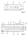
- FIG. 2 are the three components of the Fig. 1 again a little closer together and one above the other in side view.
- a correspondingly assembled operating device 38 is in Fig. 3 shown, wherein this case is installed in a hob 40 with a hob plate 41 and a support plate 48.
- Fig. 2 For the preparation of the operating device 38 is accordingly Fig. 2 attached to the control housing bottom side 13 a prefabricated carrier film 20, advantageously directly pressed. In this case, they can be held for attachment in principle by the pressing from below by means of the subsequently mounted component carrier 30.
- the carrier film 20 is permanently attached to the operating housing lower side 13, in particular by gluing or particularly advantageously by injection molding or injection molding with plastic 39, as shown in FIG Fig. 3 is shown.
- An in Fig. 3 possibly by the presentation of existing gap between carrier sheet 20 and control housing 11 and control housing bottom 13 should not occur in practice. Namely, this impairs the visual recognizability of the LCD display 34 and the LED 35 as illuminated displays.
- the function of the capacitive touch switch 43 formed by the capacitive sensor elements 22 is also impaired or possibly greatly disturbed.
- a significantly thicker layer of molded plastic 39 is provided below the carrier film 20, so as below the carrier film 20, a significantly thicker layer of molded plastic 39 is provided.
- This plastic can be provided areally and cover the entire carrier film 20, in particular overlap at the edge region and abut against the operating housing bottom side 13 for a firm connection. But then it must also be transparent or translucent plastic for the lights 35 and 36.
- the plastic 39 can run as a kind of frame circumferentially only in the outer edge region of the carrier film 20, so as to provide the fixed connection to the control housing 11. In the middle area, such a viewing window remains.
- Another simple option is the direct adhesion of the carrier film 20 with an outer peripheral adhesive edge, which leaves a larger area corresponding to the window 19.
- adhesive tape or a Mixverklebung could be provided by means of adhesive.
- FIG. 2 From the Fig. 2 can be seen with the slightly downwardly projecting or hanging projection 25 with the plug-in device 26, that even after fastening, for example injection, the carrier film 20 in the operating housing 11, an electrical contact to the counter-plug 36 and to the component carrier 30th still easily possible. Its attachment via the aforementioned latching hook, locking pins or the like. as well as a screwing on threaded projections in the control housing 11 is easily possible for the expert.
- the component carrier can be fastened in the operating housing 11 by means of projections which protrude downward from the operating housing bottom side 13. This can be done by a screw or a snap fastener. Alternatively, such corresponding protrusions can also protrude from the side, that is, inside from the control housing edge 15. Such attachment is known to the skilled person and easy to implement.
- Fig. 3 is then below the carrier film 20 and below the plastic 39 of the component carrier 30 is provided with the LCD display 34 and the LED 35 on its top 31. It can rest against the underside of the plastic 39 or the carrier film 20, but does not have. It can be seen that there is a larger air gap between the plastic 39 for fastening the carrier foil 20 to the operating housing lower side 13 and the upper side of the LCD display 34. This does not bother the function as well as the appearance.
- the electrical contacting of the component carrier 30 to the carrier film 20 is not shown here, for the skilled person but due to the Fig. 1 easy to imagine.
- the operating housing 11 is seated with the lower edge 16 of the Whyge Reifenands 15 and the attached bottom seal 18 on a conventional support plate 48 of the hob 40, sit on the well-known heating also not shown here.
- the operating housing upper side 12 is pressed against the underside 46 of the hob plate 41.
- a hob plate 41 made of glass ceramic which is grooved on the underside, a not quite perfect system or a system with air gaps can be provided.
- an at least partially translucent or transparent adaptation layer which is advantageously elastic, for example a soft silicone or similar material which may not be electrically conductive.
- the operating device produced according to the invention and shown in the figures is characterized in that in the control housing relatively easily other carrier films and / or other component carrier 30 can be installed with the advantage that not every time a complete new operating device must be designed and their Accommodation in a hob.
- Fig. 1 clearly shows that carrier film 20 and / or component carrier 30 can be varied relatively easily, while the other parts, in particular the control housing 11, can remain the same.
- the corresponding Fig. 3 can lie on the bottom 46 of a hob plate 41 as a control panel or control surface, and the attachment of the carrier film 20 with the capacitive sensor elements 22 thereon directly to the control housing bottom side 13, a defined geometric arrangement is given.
- both the optical representation ratios for the LEDs in the form of the LCD display 34 and the LED 35 and the electrical conditions for the operation of the capacitive touch switch 43 are good.
Abstract
Eine Bedieneinrichtung für ein Elektrogerät weist einen kapazitiven Berührungsschalter mit kapazitivem Sensorelement und ein Bediengehäuse auf, wobei das Sensorelement auf einer Trägerfolie angeordnet ist, auf der elektrische Leiter zum Anschluss des Sensorelements zu einer Anschlusseinrichtung an der Trägerfolie verlaufen. Das Bediengehäuse weist eine flache Bediengehäuseoberseite auf mit einem nach unten abstehenden umlaufenden Bediengehäuserand, an deren Unterseite die Trägerfolie befestigt ist. In dem Bediengehäuse ist unterhalb der Trägerfolie ein Bauteilträger mit elektrischen Bauteilen und einer Leuchtanzeige vorgesehen, der Bauteilträger an die Trägerfolie elektrisch angeschlossen ist, wobei die Trägerfolie und die Bediengehäuseoberseite zumindest bereichsweise lichtdurchlässig sind oberhalb der Leuchtanzeige.An operating device for an electrical appliance has a capacitive touch switch with a capacitive sensor element and an operating housing, wherein the sensor element is arranged on a carrier film on which electrical conductors for connecting the sensor element to a connection device on the carrier film extend. The operating housing has a flat operating housing upper side with a downwardly projecting peripheral operating housing edge, on the underside of the carrier film is attached. In the operating housing, a component carrier with electrical components and a light display is provided below the carrier film, the component carrier is electrically connected to the carrier film, wherein the carrier film and the operating housing top are at least partially transparent above the light indicator.
Description
Die Erfindung betrifft eine Bedieneinrichtung für ein Elektrogerät mit mindestens einem kapazitiven Berührungsschalter, ein Elektrogerät mit einer solchen Bedieneinrichtung sowie ein Verfahren zur Herstellung einer solchen Bedieneinrichtung.The invention relates to an operating device for an electrical appliance with at least one capacitive touch switch, an electrical appliance with such an operating device and a method for producing such an operating device.
Aus der
Aus der
Der Erfindung liegt die Aufgabe zugrunde, eine eingangs genannte Bedieneinrichtung, ein damit versehenes Elektrogerät sowie ein Verfahren zur Herstellung einer solchen Bedieneinrichtung zu schaffen, mit denen Probleme des Stands der Technik gelöst werden können und es insbesondere möglich ist, kapazitive Berührungsschalter bzw. dafür vorgesehene kapazitive Sensorelemente auf praxistaugliche Art und Weise in einem Bediengehäuse anzuordnen.The invention has for its object to provide an aforementioned control device, an electrical device provided therewith and a method for producing such a control device with which problems of the prior art can be solved and it is particularly possible to capacitive touch switch or capacitive To arrange sensor elements in a practical manner in a control housing.
Gelöst wird diese Aufgabe durch eine Bedieneinrichtung mit den Merkmalen des Anspruchs 1, ein Elektrogerät mit den Merkmalen des Anspruchs 12 sowie ein Verfahren mit den Merkmalen des Anspruchs 14. Vorteilhafte sowie bevorzugte Ausgestaltungen der Erfindung sind Gegenstand der weiteren Ansprüche und werden im Folgenden näher erläutert. Dabei werden manche der Merkmale nur für die Bedieneinrichtung, für das Elektrogerät oder für das Herstellungsverfahren beschrieben. Sie sollen jedoch unabhängig davon sowohl für die Bedieneinrichtung als auch für das Elektrogerät und für das Herstellungsverfahren selbständig und unabhängig voneinander gelten können. Der Wortlaut der Ansprüche wird durch ausdrückliche Bezugnahme zum Inhalt der Beschreibung gemacht.This object is achieved by an operating device with the features of claim 1, an electrical appliance with the features of
Es ist vorgesehen, dass die Bedieneinrichtung für das Elektrogerät mindestens einen kapazitiven Berührungsschalter und ein Bediengehäuse aufweist. Der kapazitive Berührungsschalter weist ein kapazitives Sensorelement auf bzw. wird auch durch ein solches gebildet. Dieses Sensorelement wiederum ist auf einer Trägerfolie bzw. einem dünnen und elastischen und flexiblen Träger angeordnet, beispielsweise einer sogenannten Flexleiterplatte, vorteilhaft hergestellt durch ein entsprechend bekanntes Beschichtungsverfahren. Auf der Trägerfolie sind auch elektrische Leiter vorgesehen, um insbesondere das kapazitive Sensorelement elektrisch anzuschließen. Dazu verlaufen sie zu einer Anschlusseinrichtung, die an der Trägerfolie vorgesehen bzw. befestigt ist. Eine solche Anschlusseinrichtung kann eine fertige Steckverbindung sein, insbesondere eine Steckerbuchse. Alternativ können es einfache Kontaktfelder zur Kontaktierung durch Anlegen oder Aufklemmen bzw. Anschweißen oder Anlöten sein. Das Bediengehäuse weist eine flache Bediengehäuseoberseite auf, die unten und/oder oben sogar eben bzw. plan ausgebildet sein kann. Des Weiteren weist das Bediengehäuse einen zumindest teilweise nach unten abstehenden Bediengehäuserand auf, der zumindest teilweise, vorteilhaft weitgehend, umläuft bzw. umlaufend ausgebildet ist. Somit ist das Bediengehäuse nach unten weitgehend offen, wobei hier zum Verschluss eine Bodenplatte odgl. vorgesehen sein kann. Des Weiteren ist die Trägerfolie an der Unterseite der Bediengehäuseoberseite befestigt, also sozusagen von unten in das Bediengehäuse eingebracht und dann darin befestigt.It is provided that the operating device for the electrical appliance has at least one capacitive touch switch and a control housing. The capacitive touch switch has or is also formed by a capacitive sensor element. This sensor element in turn is arranged on a carrier foil or a thin and elastic and flexible carrier, for example a so-called flex circuit plate, advantageously produced by a correspondingly known coating method. On the carrier foil and electrical conductors are provided to electrically connect in particular the capacitive sensor element. For this purpose, they run to a connection device, which is provided or attached to the carrier film. Such a connection device may be a ready-made plug connection, in particular a socket. Alternatively, it may be simple contact fields for contacting by applying or clamping or welding or soldering. The operating housing has a flat operating housing upper side, which may even be flat or planar at the bottom and / or top. Furthermore, the operating housing has an operating housing edge projecting at least partially downwards, which at least partially, advantageously largely, revolves or is formed circumferentially. Thus, the control housing is downwardly largely open, in which case the closure of a bottom plate or the like. can be provided. Furthermore, the carrier film is attached to the underside of the control housing top, so to speak introduced from below into the control housing and then secured therein.
Erfindungsgemäß ist vorgesehen, dass in dem Bediengehäuse unterhalb der Trägerfolie noch ein Bauteilträger mit elektrischen Bauteilen und mit mindestens einer Leuchtanzeige der Bedieneinrichtung oder für die Bedieneinrichtung vorgesehen ist. So kann die Trägerfolie weitgehend oder ausschließlich die kapazitiven Sensorelemente samt den elektrischen Leitern und der Anschlusseinrichtung aufweisen, während die Hauptbestandteile für eine Bedieneinrichtung bzw. zur Steuerung des Elektrogeräts auf diesem Bauteilträger angeordnet sind. So kann die Trägerfolie auch flach ausgebildet sein sowie ihre Flexibilität bewahren, die durch aufgebrachte Bauteile wie SMD-Bauteilen odgl. beeinträchtigt werden würde. Die Trägerfolie ist an den Bauteilträger elektrisch angeschlossen, vorteilhaft durch die genannte Anschlusseinrichtung. Schließlich sind die Trägerfolie und die Bediengehäuseoberseite zumindest bereichsweise lichtdurchlässig, und zwar vorteilhaft oberhalb der genannten Leuchtanzeige. So ist diese durch die Bediengehäuseoberseite und durch die Trägerfolie hindurch erkennbar.According to the invention, a component carrier with electrical components and with at least one illuminated display of the operating device or for the operating device is provided in the operating housing below the carrier film. Thus, the carrier film may largely or exclusively comprise the capacitive sensor elements together with the electrical conductors and the connection device, while the main components for an operating device or for controlling the electrical device are arranged on this component carrier. Thus, the carrier film may also be formed flat and retain their flexibility or the like by applied components such as SMD components. would be affected. The carrier film is electrically connected to the component carrier, advantageously by the said connection device. Finally, the carrier film and the upper side of the control housing are translucent at least in some areas, advantageously above said light indicator. So this is recognizable through the control housing top and through the carrier film.
Somit ist mit der Erfindung eine sehr gute Integration eines kapazitiven Berührungsschalters und einer Leuchtanzeige in eine Bedieneinrichtung möglich, insbesondere in eine Bedieneinrichtung mit einem Bediengehäuse. Durch die Anordnung in einem solchen Bediengehäuse ist zum einen eine eigenständig handhabbare Baueinheit erreicht, zum anderen kann eine thermische Dämmung, elektrische Isolation und auch ein Schutz vor Feuchtigkeit erreicht werden. Vor allem kann eine solche Bedieneinrichtung, die nicht nur ein Bediengehäuse aufweist, sondern weitgehend in diesem Bediengehäuse angeordnet ist, leicht in ein Elektrogerät eingebaut werden, beispielsweise unter eine Bedienblende oder eine Bedienoberfläche wie beispielsweise bei einem Kochfeld unter einer Kochfeldplatte oder bei einem sonstigen Elektrogerät eine Vorderseite oder Oberseite.Thus, with the invention, a very good integration of a capacitive touch switch and a light display in an operating device is possible, in particular in an operating device with a control housing. By the arrangement in such a Operating housing is on the one hand achieved a self-contained assembly, on the other hand, a thermal insulation, electrical insulation and protection against moisture can be achieved. Above all, such an operating device, which not only has a control housing, but is largely arranged in this control housing, easily be installed in an electrical appliance, for example, under a control panel or a user interface such as a hob under a cooktop or other electrical appliance Front or top.
In vorteilhafter Ausgestaltung der Erfindung ist die Trägerfolie an der Unterseite der Bediengehäuseoberseite dauerhaft und unlösbar befestigt, insbesondere kann sie integral mit dieser hergestellt sein, alternativ mittels Kunststoffspritzguss an eine fertige Bediengehäuseoberseite angespritzt sein, also in einem Bediengehäuse durch Anspritzen befestigt sein. Bei einer solchen sogenannten In-Mould-Methode ist auch eine exakte Anordnung der kapazitiven Berührungsschalter bzw. kapazitiven Sensorelemente zum Bediengehäuse bzw. zur Bediengehäuseoberseite erreicht, was für die Funktionsweise von kapazitiven Berührungsschaltern sehr wichtig ist. Dazu kann die Trägerfolie vor dem Anspritzen direkt an die Unterseite der Bediengehäuseoberseite angelegt sein.In an advantageous embodiment of the invention, the carrier film on the underside of the control housing top permanently and permanently attached, in particular, it can be made integral with this, be injection molded by means of plastic injection to a finished control housing top, so be fixed in a control housing by injection. In such a so-called in-mold method, an exact arrangement of the capacitive touch switch or capacitive sensor elements to the control housing or the control housing top is achieved, which is very important for the operation of capacitive touch switches. For this purpose, the carrier film can be applied directly to the underside of the control housing top prior to injection molding.
Vorteilhaft liegt dabei die Trägerfolie großflächig bzw. vollflächig an der Unterseite der Bediengehäuseoberseite an. Dies erfolgt möglichst ohne Einschluss von Luftblasen odgl., so dass also keine Luftspalte entstehen. Diese beeinträchtigen die Funktionsweise eines kapazitiven Berührungsschalters nämlich sehr negativ.Advantageously, the carrier film is applied over a large area or over the entire surface to the underside of the operating housing upper side. This is done as possible without inclusion of air bubbles or the like, so that therefore no air gaps. These affect the operation of a capacitive touch switch namely very negative.
Bei der Anordnung der Trägerfolie in dem Bediengehäuse kann vorgesehen sein, dass die Anschlusseinrichtung der Trägerfolie noch zugänglich ist bzw. frei absteht, wenn die Trägerfolie an der Unterseite der Bediengehäuseoberseite befestigt worden ist. So ist ein guter und sicherer elektrischer Anschluss an den Bauteilträger bei dessen Einbau in das Bediengehäuse möglich.In the arrangement of the carrier film in the operating housing can be provided that the connection device of the carrier film is still accessible or freely protrudes when the carrier film has been attached to the underside of the control housing top. Thus, a good and safe electrical connection to the component carrier during its installation in the operating housing is possible.
Der Bauteilträger wird vorteilhaft im Bediengehäuse befestigt und eben mittels der genannten Anschlusseinrichtung mit der Trägerfolie elektrisch verbunden, so dass die darauf vorhandenen kapazitiven Sensorelemente ausgewertet und verwendet werden können. Eine Befestigung des Bauteilträgers im Bediengehäuse kann vorteilhaft auf an sich bekannte Art und Weise erfolgen, beispielsweise kann nach Anstecken oder Anschließen der Anschlusseinrichtung der Bauteilträger auf Führungsvorsprünge gesteckt und mittels Rasteinrichtungen odgl. befestigt werden.The component carrier is advantageously fastened in the operating housing and just electrically connected to the carrier film by means of the abovementioned connection device, so that the capacitive sensor elements present thereon can be evaluated and used. An attachment of the component carrier in the operating housing can advantageously be done in a known manner, for example, after plugging or connecting the connection device of the component carrier can be placed on guide projections and odgl by means of locking devices. be attached.
Für die Trägerfolie und den Bauteilträger kann vorteilhaft gelten, dass mindestens ein kapazitives Sensorelement oberhalb der Leuchtanzeige auf dem Bauteilträger angeordnet ist, besonders vorteilhaft direkt über der Leuchtanzeige. Somit ist es möglich, dass eine Bedienperson den Finger oberhalb dieser Leuchtanzeige auf eine Bedienblende oder ein Bedienfeld auflegt und dann den durch dieses kapazitive Sensorelement gebildeten kapazitiven Berührungsschalter bedient. Es können aber auch kapazitive Sensorelemente neben derartigen Leuchtanzeigen vorgesehen sein. Die Leuchtanzeigen selbst können allgemein ausgebildet sein wie im Stand der Technik bekannt, entweder nur als leuchtende Fläche, also leuchtendes Symbol oder als beleuchtetes und veränderbares Symbol, beispielsweise durch Sieben-Segment-Anzeigen gebildet von LED.For the carrier film and the component carrier, it can advantageously be considered that at least one capacitive sensor element is arranged above the illuminated display on the component carrier, particularly advantageously directly above the illuminated display. Thus, it is possible for an operator to place his finger on a control panel or a control panel above this light display and then operate the capacitive touch switch formed by this capacitive sensor element. But it can also be provided capacitive sensor elements in addition to such lights. The light indicators themselves may be generally designed as known in the art, either only as a luminous surface, so luminous symbol or as an illuminated and changeable symbol, for example by seven-segment displays formed by LED.
In Ausgestaltung der Erfindung ist der lichtdurchlässige Bereich der Bediengehäuseoberseite im Wesentlichen lichtdurchlässig bzw. zu mindestens 90% durchsichtig. Dazu kann er vorteilhaft ein eingesetztes Fenster aus entsprechend lichtdurchlässigem Material aufweisen. Alternativ und vorteilhaft ist der Großteil der Bediengehäuseoberseite lichtdurchlässig und aus lichtdurchlässigem Material hergestellt, wobei eine Maskierung oder Abdeckung die Lichtdurchlässigkeit auf bestimmte Bereiche beschränkt, die eben lichtdurchlässig oder durchsichtig sein sollen bzw. durch welche hindurch die Leuchtanzeigen erkennbar sein sollen.In an embodiment of the invention, the translucent region of the operating housing upper side is substantially translucent or at least 90% transparent. For this purpose, it can advantageously have an inserted window of correspondingly transparent material. Alternatively and advantageously, the majority of the control housing top is translucent and made of translucent material, with a mask or cover the light transmission limited to certain areas that just translucent or translucent or through which the lights should be visible.
In ähnlicher Form ist die Trägerfolie nicht nur bereichsweise lichtdurchlässig, sondern insgesamt lichtdurchlässig bzw. besteht aus einem an sich lichtdurchlässigen oder sogar zu mindestens 90% durchsichtigen Material. Eine vorgenannte Maskierung oder Abdeckung braucht an der Trägerfolie nicht vorgesehen zu sein, da dies durch die darüberliegende Bediengehäuseoberseite mit einer solchen Maskierung bzw. Abdeckung übernommen wird.In a similar form, the carrier film is not only partially translucent, but a total of translucent or consists of a translucent or even at least 90% transparent material. An aforementioned mask or cover need not be provided on the carrier film, as this is taken over by the overlying control housing top with such a mask or cover.
In Ausgestaltung der Erfindung kann das Bediengehäuse integral und einteilig hergestellt sein. Dabei kann es vorteilhaft aus einem durchgehend gleichen Material ausgebildet sein, so dass die Herstellung, insbesondere ein Kunststoffspritzvorgang, einfacher ist. Angesichts der vorgenannten Ausbildung zumindest eines Bereichs der Bediengehäuseoberseite aus lichtdurchlässigem oder durchsichtigem Material sollte das gesamte Bediengehäuse aus diesem lichtdurchlässigen bzw. durchsichtigen Material hergestellt sein. Durch die relativ einfache nachträgliche Anbringung der Abschirmung bzw. Abdeckung kann die Lichtdurchlässigkeit auf die gewünschten Bereiche eingeschränkt werden. Eine solche Abschirmung oder Abdeckung kann sowohl auf die Außenseite als auch auf die Innenseite des Bediengehäuses aufgebracht werden. Sie kann nicht nur an der Bediengehäuseoberseite vorgesehen sein, sondern auch an dem vorgenannten seitlichen Bediengehäuserand. So kann ein seitliches Abstrahlen von Licht, unter Umständen auf ungewünschte Art und Weise, vermieden werden. Die vorgenannte Abschirmung bzw. Abdeckung sollte daneben mindestens einen entsprechenden Ausschnitt aufweisen, der die Leuchtanzeigen auf dem Bauteilträger freilässt, so dass sie von oben zu sehen sind.In an embodiment of the invention, the operating housing can be made integral and one-piece. It may advantageously be formed from a continuous same material, so that the production, in particular a plastic injection process, is simpler. In view of the above-mentioned construction of at least a portion of the operating housing upper side made of translucent or transparent material, the entire operating housing should be made of this translucent or transparent material. Due to the relatively simple subsequent attachment of the shield or cover, the light transmission can be limited to the desired areas. Such a shield or cover can be applied both to the outside and to the inside of the operating housing. It can be provided not only on the control housing top, but also on the aforementioned lateral Bediengehäuserand. So can a lateral emission of light, possibly in an undesirable manner, be avoided. The abovementioned shielding or cover should have at least one corresponding cutout next to it, which leaves the illuminated displays on the component carrier so that they can be seen from above.
Der nach unten stehende, weitgehend umlaufende Bediengehäuserand dient dazu, dass darin der Bauteilträger aufgenommen werden kann. Des Weiteren kann er dazu dienen, wenn er an einer Unterkante eine Ebene definiert, dass er damit auf einer großflächigen Unterlage, beispielsweise auf einer Tragplatte oder einem Tragblech eines Kochfelds, aufliegt und so die Anordnung der Bedieneinrichtung bzw. des Bediengehäuses in dem Elektrogerät sicher und stabil ist. In weiterer Ausgestaltung der Erfindung können an dem unteren Bereich des Bediengehäuserands, vorteilhaft an der Unterkante, Dichtmittel nach unten vorgesehen sein. Sie können beispielsweise als Dichtlippe oder Dichtschnur ausgebildet sein. Diese Dichtmittel können eine abgedichtete Anlage auf der vorgenannten Unterlage schaffen. So ist insbesondere ein Schutz gegen Eindringen von Schmutz und/oder Feuchtigkeit gewährleistet. Derartige Dichtmittel können nachträglich bzw. separat angeordnet sein, alternativ können sie auch direkt angespritzt sein. Dann entfällt ein nachträglicher Montageschritt.The downwardly extending, largely encircling operator housing edge serves to accommodate the component carrier therein. Furthermore, it can serve, if it defines a plane at a lower edge, so that it rests on a large-surface support, for example on a support plate or a support plate of a hob, and so the arrangement of the operating device or the operating housing in the electrical appliance safely and is stable. In a further embodiment of the invention may be provided at the lower portion of the Bediengehäuserands, advantageously at the lower edge, sealant down. They can be designed for example as a sealing lip or sealing cord. These sealants can provide a sealed abutment on the aforementioned pad. In particular, protection against ingress of dirt and / or moisture is ensured. Such sealing means can be arranged subsequently or separately, alternatively, they can also be molded directly. Then there is no need for a subsequent assembly step.
Ein erfindungsgemäßes Elektrogerät kann ein Kochfeld mit einer lichtdurchlässigen Kochfeldplatte sein, welche vorteilhaft eine an sich bekannte Glaskeramik-Kochfeldplatte oder eine Hartglas-Kochfeldplatte ist. Das Kochfeld weist eine vorbeschriebene Bedieneinrichtung auf, welche unter der Kochfeldplatte angeordnet ist bzw. welche an die Unterseite der Kochfeldplatte angedrückt ist. So liegt die Bediengehäuseoberseite vorteilhaft direkt an der Unterseite der Kochfeldplatte an, unter Umständen mit einer elastischen Anpassungsschicht odgl. dazwischen. Die Bedieneinrichtung weist dabei mit den kapazitiven Sensorelementen bzw. den davon gebildeten kapazitiven Berührungsschaltern die Eingabeelemente für das Kochfeld auf, wobei auf dem vorbeschriebenen Bauteilträger eine Steuerung sowie wesentliche Teile für die Funktionen der Steuerung des Kochfelds vorgesehen sind. Andere Elektrogeräte können Spülmaschinen, Waschmaschinen, Backöfen, Dunstabzugshauben odgl. sein.An inventive electrical appliance may be a hob with a translucent hob plate, which is advantageously a known glass ceramic hob plate or a hard glass hob plate. The cooktop has a previously described operating device, which is arranged under the cooktop panel or which is pressed against the underside of the cooktop panel. Thus, the control housing top is advantageous directly to the bottom of the hob plate, possibly with an elastic matching layer or the like. between. In this case, the operating device has the input elements for the hob with the capacitive sensor elements or the capacitive touch switches formed therefrom, wherein a control and essential parts for the functions of the control of the hob are provided on the above-described component carrier. Other electrical appliances may include dishwashers, washing machines, ovens, cooker hoods or the like. be.
Um die Bedieneinrichtung an die Unterseite der Kochfeldplatte anzudrücken, kann vorgesehen sein, dass sie auf eine an sich übliche Tragplatte bzw. ein sogenanntes Tragblech des Kochfelds aufgelegt ist. Hier sollten mechanische Positionsmarkierungen vorgesehen sein, damit die Bedieneinrichtung bzw. deren Bediengehäuse an der exakt richtigen Stelle anliegt. Es sollten auch Haltemittel vorgesehen sein, um zu verhindern, dass die Bedieneinrichtung seitlich verschoben wird. Diese können rastend oder einfach nur eine seitliche Bewegung begrenzend ausgebildet sein. Durch das Andrücken an die Unterseite der Kochfeldplatte ist eigentlich eine Bewegung der Bedieneinrichtung bei zusammengebautem Kochfeld nicht mehr möglich, zumindest ein Abheben.To press the operating device to the underside of the hob plate, it can be provided that it is placed on a conventional support plate or a so-called support plate of the hob. Here, mechanical position markings should be provided so that the operating device or its operating housing rests on the exact right place. It should also be provided holding means to prevent the operating device is moved laterally. These can be restraining or just limiting a lateral movement be educated. By pressing against the underside of the hob plate actually a movement of the control device when assembled hob is no longer possible, at least one lifting.
Bei einem erfindungsgemäßen Verfahren zur Herstellung einer vorbeschriebenen Bedieneinrichtung wird eine Trägerfolie hergestellt mit den darauf angeordneten kapazitiven Sensorelementen und den elektrischen Leitern. Dann wird diese mit einer vorgenannten Anschlusseinrichtung versehen, beispielsweise für einen Steckanschluss bzw. als Steckanschlusseinrichtung. Diese Trägerfolie wird dann an der Unterseite der Bediengehäuseoberseite befestigt, wobei das Bediengehäuse selbst schon ein weitgehend fertig hergestelltes Teil ist. Diese Befestigung kann beispielsweise mittels Kunststoffspritzguss erfolgen als vorbeschriebenes In-Mould-Verfahren. Alternativ kann eine Verklebung vorgesehen sein oder ein Einklemmen. Es ist auch möglich, die Trägerfolie bei Herstellung des Bediengehäuses bzw. der Bediengehäuseoberseite direkt zu integrieren bzw. einzuspritzen.In a method according to the invention for producing a previously described operating device, a carrier foil is produced with the capacitive sensor elements and the electrical conductors arranged thereon. Then it is provided with an aforementioned connection device, for example for a plug connection or as a plug connection device. This carrier film is then attached to the underside of the control housing upper side, wherein the control housing itself is already a largely finished manufactured part. This attachment can be done for example by means of plastic injection molding as described above in-mold process. Alternatively, a bond may be provided or a pinching. It is also possible to directly integrate or inject the carrier film during production of the operating housing or the upper side of the operating housing.
Anschließend wird ein Bauteilträger mit den vorgenannten elektrischen Bauteilen und/oder einer Steuerung der Bedieneinrichtung, insbesondere mittels eines Mikrocontrollers, in dem Bediengehäuse unterhalb der Trägerfolie angeordnet. Dazu können eben in dem Bediengehäuse Positioniermittel und Haltemittel wie Rasthaken odgl. vorgesehen sein, an welchen der Bauteilträger durch einfaches Andrücken bzw. Aufdrücken befestigt wird.Subsequently, a component carrier with the aforementioned electrical components and / or a control of the operating device, in particular by means of a microcontroller, arranged in the operating housing below the carrier film. For this purpose, just in the control housing positioning means and holding means such as latching hooks or the like. be provided, to which the component carrier is attached by simply pressing or pressing.
Diese und weitere Merkmale gehen außer aus den Ansprüchen auch aus der Beschreibung und den Zeichnungen hervor, wobei die einzelnen Merkmale jeweils für sich allein oder zu mehreren in Form von Unterkombinationen bei einer Ausführungsform der Erfindung und auf anderen Gebieten verwirklicht sein und vorteilhafte sowie für sich schutzfähige Ausführungen darstellen können, für die hier Schutz beansprucht wird. Die Unterteilung der Anmeldung in einzelne Abschnitte sowie Zwischen-Überschriften beschränken die unter diesen gemachten Aussagen nicht in ihrer Allgemeingültigkeit.These and other features will become apparent from the claims but also from the description and drawings, wherein the individual features each alone or more in the form of sub-combinations in an embodiment of the invention and in other fields be realized and advantageous and protectable Represent embodiments for which protection is claimed here. The subdivision of the application into individual sections as well as intermediate headings does not restrict the general validity of the statements made thereunder.
Ein Ausführungsbeispiel der Erfindung ist in den Zeichnungen schematisch dargestellt und wird im Folgenden näher erläutert. In den Zeichnungen zeigen:
- Fig. 1
- ein Bediengehäuse, eine Trägerfolie und einen Bauteilträger für eine erfindungsgemäße Bedieneinrichtung in auseinandergezogener Darstellung,
- Fig. 2
- die drei Teile für die Bedieneinrichtung aus
Fig. 1 auseinandergezogen in Seitenansicht und - Fig. 3
- ein erfindungsgemäßes Kochfeld mit einer darunter angeordneten erfindungsgemäßen Bedieneinrichtung im montierten Zustand.
- Fig. 1
- an operating housing, a carrier film and a component carrier for an inventive operating device in an exploded view,
- Fig. 2
- the three parts for the operating device
Fig. 1 exploded in side view and - Fig. 3
- a cooking hob according to the invention with a control device according to the invention arranged underneath in the mounted state.
In
Wie eingangs beschrieben worden ist, sollte zumindest ein Teil der Bediengehäuseoberseite 12 lichtdurchlässig oder durchsichtig sein. Dies kann allgemein durch ein eingesetztes oder unter Umständen aus einem anderen Material eingespritztes Fenster aus entsprechend durchsichtigem Material erreicht werden. Alternativ und vorteilhaft besteht das gesamte Bediengehäuse 11 aus einem entsprechend lichtdurchlässigen oder durchsichtigen Material, beispielsweise Acrylglas, Polycarbonat odgl.. Dann sollte aber von oben nicht das gesamte Innenleben des Bediengehäuses 11 erkannt werden können. Deswegen kann eine lichtundurchlässige Beschichtung als Abschirmung bzw. Abdeckung an der Außenseite oder der Innenseite bzw. der Bediengehäuseoberseite 12 und/oder der Bediengehäuseunterseite 13 vorgesehen sein. Diese sollte ein gestrichelt dargestelltes Fenster 19 freilassen, durch welches dann eben die erfindungsgemäße Lichtdurchlässigkeit bzw. Durchsichtigkeit erreicht werden kann.As described above, at least a part of the operating housing
Wie aus der
Unterhalb des Bediengehäuses 11 ist in der
Die Trägerfolie 20 ist hier rechteckig dargestellt, wie auch das Bediengehäuse 11, sie kann aber auch eine andere bzw. beliebige Form haben. Allerdings ist sie deutlich kleiner, wobei sie gleichzeitig deutlich größer ist als das Fenster 19. Der hier zu erkennende breite überstehende Rand außerhalb der Sensorelemente 22 bzw. Leiter 23 dient zur Befestigung im Bediengehäuse 11, wie nachfolgend noch näher erläutert wird.The
Unterhalb der Trägerfolie 20 ist in entsprechender Schrägdarstellung ein Bauteilträger 30 zu sehen, beispielsweise in Form einer üblichen Leiterplatte. Der Bauteilträger 30 ist grundsätzlich auch rechteckig, muss dies aber nicht sein, wobei er wiederum deutlich größer ist als die Trägerfolie 20 und vorteilhaft zumindest weitgehend dem Innenraum des Bediengehäuses 11 entspricht. In Eckbereichen weist der Bauteilträger 30 Befestigungslöcher 32 auf. Damit kann er beispielsweise an entsprechenden Rastvorsprüngen befestigt werden, die von der Bediengehäuseunterseite 13 nach unten stehen.Below the
Auf einer Oberseite 31 weist der Bauteilträger 30 mehrere Bauteile auf, nämlich ein großflächiges LCD-Display 34, rechts daneben eine einfache LED 35 und an der Vorderseite eine Gegen-Steckeinrichtung 36. In diese Gegen-Steckeinrichtung 36 kann von oben oder von der Seite die Steckeinrichtung 26 der Trägerfolie 20 eingesteckt werden. Des Weiteren ist auf dem Bauteilträger 30 vorteilhaft ein Mikrocontroller angeordnet, also die sogenannte Intelligenz für die Bedieneinrichtung.On a
In der
Zur Herstellung der Bedieneinrichtung 38 wird entsprechend
Aus der
Der Bauteilträger kann in dem Bediengehäuse 11 mittels Vorsprünge befestigt werden, die von der Bediengehäuseunterseite 13 nach unten abstehen. Daran kann eine Schraubbefestigung oder eine Rastbefestigung erfolgen. Alternativ können auch von der Seite, also innen vom Bediengehäuserand 15, solche entsprechenden Vorsprünge abstehen. Eine derartige Befestigung ist dem Fachmann aber bekannt und leicht zu realisieren.The component carrier can be fastened in the operating
Im zusammengebauten Zustand der Bedieneinrichtung 38 entsprechend
Das Bediengehäuse 11 sitzt mit der Unterkante 16 des Bediengehäuserands 15 bzw. der unten daran angebrachten Dichtung 18 auf einem üblichen Tragblech 48 des Kochfelds 40 auf, auf dem bekanntlich auch hier nicht dargestellte Heizeinrichtungen aufsitzen. Gleichzeitig ist dabei die Bediengehäuseoberseite 12 an die Unterseite 46 der Kochfeldplatte 41 angedrückt. Hier kann insbesondere bei einer an der Unterseite genoppten Kochfeldplatte 41 aus Glaskeramik eine nicht ganz perfekte Anlage bzw. eine Anlage mit Luftspalten vorgesehen sein. Um dies auszugleichen, kann allgemein eine zumindest teilweise lichtdurchlässige bzw. durchsichtige Anpassungsschicht vorgesehen sein bzw. eingespritzt werden, die vorteilhaft elastisch ist, beispielsweise ein weiches Silikon oder ähnliches Material, das nicht elektrisch leitfähig sein darf.The operating
Die gemäß der Erfindung hergestellte und in den Figuren dargestellte Bedieneinrichtung zeichnet sich dadurch aus, dass in das Bediengehäuse relativ leicht andere Trägerfolien und/oder andere Bauteilträger 30 eingebaut werden können mit dem Vorteil, dass nicht jedes Mal eine komplette neue Bedieneinrichtung entworfen werden muss sowie deren Unterbringung in einem Kochfeld. Gerade die
Durch die nach oben vorgesehene geschlossene Bediengehäuseoberseite 12, die entsprechend
Claims (15)
Applications Claiming Priority (1)
| Application Number | Priority Date | Filing Date | Title |
|---|---|---|---|
| DE102015217856.0A DE102015217856A1 (en) | 2015-09-17 | 2015-09-17 | Operating device for an electrical appliance, electrical appliance and method for producing an operating device |
Publications (1)
| Publication Number | Publication Date |
|---|---|
| EP3145082A1 true EP3145082A1 (en) | 2017-03-22 |
Family
ID=56855363
Family Applications (1)
| Application Number | Title | Priority Date | Filing Date |
|---|---|---|---|
| EP16187189.2A Withdrawn EP3145082A1 (en) | 2015-09-17 | 2016-09-05 | Operating device for an electrical device and method for producing an operating device |
Country Status (2)
| Country | Link |
|---|---|
| EP (1) | EP3145082A1 (en) |
| DE (1) | DE102015217856A1 (en) |
Cited By (1)
| Publication number | Priority date | Publication date | Assignee | Title |
|---|---|---|---|---|
| WO2022022964A1 (en) * | 2020-07-27 | 2022-02-03 | BSH Hausgeräte GmbH | Household appliance and control panel assembly and touch module thereof |
Citations (5)
| Publication number | Priority date | Publication date | Assignee | Title |
|---|---|---|---|---|
| EP0859467A1 (en) | 1997-02-17 | 1998-08-19 | E.G.O. ELEKTRO-GERÄTEBAU GmbH | Touch switch with sensor key |
| US20100079153A1 (en) * | 2008-09-25 | 2010-04-01 | Stoneridge Control Devices, Inc. | Touch Sensor System and Method |
| US20130027349A1 (en) * | 2010-04-06 | 2013-01-31 | Continental Auotmotive GmbH | Capacitive proximity switch |
| US20130194759A1 (en) * | 2012-02-01 | 2013-08-01 | Sunggu Kang | Touch sensor with integrated signal bus extensions |
| DE102013211296A1 (en) | 2013-06-17 | 2014-12-18 | E.G.O. Elektro-Gerätebau GmbH | Holding device for an assembly and electrical appliance |
Family Cites Families (2)
| Publication number | Priority date | Publication date | Assignee | Title |
|---|---|---|---|---|
| DE102012010321B4 (en) * | 2012-05-21 | 2024-03-07 | E.G.O. Elektro-Gerätebau GmbH | Sensor element device for a capacitive touch switch of an operating device, operating device and hob |
| DE102013021879B4 (en) * | 2013-12-21 | 2017-10-19 | Diehl Ako Stiftung & Co. Kg | Touch and / or proximity sensitive input device |
-
2015
- 2015-09-17 DE DE102015217856.0A patent/DE102015217856A1/en not_active Ceased
-
2016
- 2016-09-05 EP EP16187189.2A patent/EP3145082A1/en not_active Withdrawn
Patent Citations (5)
| Publication number | Priority date | Publication date | Assignee | Title |
|---|---|---|---|---|
| EP0859467A1 (en) | 1997-02-17 | 1998-08-19 | E.G.O. ELEKTRO-GERÄTEBAU GmbH | Touch switch with sensor key |
| US20100079153A1 (en) * | 2008-09-25 | 2010-04-01 | Stoneridge Control Devices, Inc. | Touch Sensor System and Method |
| US20130027349A1 (en) * | 2010-04-06 | 2013-01-31 | Continental Auotmotive GmbH | Capacitive proximity switch |
| US20130194759A1 (en) * | 2012-02-01 | 2013-08-01 | Sunggu Kang | Touch sensor with integrated signal bus extensions |
| DE102013211296A1 (en) | 2013-06-17 | 2014-12-18 | E.G.O. Elektro-Gerätebau GmbH | Holding device for an assembly and electrical appliance |
Cited By (1)
| Publication number | Priority date | Publication date | Assignee | Title |
|---|---|---|---|---|
| WO2022022964A1 (en) * | 2020-07-27 | 2022-02-03 | BSH Hausgeräte GmbH | Household appliance and control panel assembly and touch module thereof |
Also Published As
| Publication number | Publication date |
|---|---|
| DE102015217856A1 (en) | 2017-03-23 |
Similar Documents
| Publication | Publication Date | Title |
|---|---|---|
| EP2853027B1 (en) | Arrangement with sensor element device on a component carrier for a capacitive touch switch of an operating device, operating device, and cooking hob with such an arrangement | |
| WO2011003912A1 (en) | Operating unit for an electrical device | |
| DE10123633A1 (en) | sensor element | |
| EP1662207B1 (en) | Control device for a household appliance | |
| DE102017218243B3 (en) | Method for producing at least part of a touch-sensitive operating device, touch-sensitive operating device and motor vehicle | |
| DE102014018470A1 (en) | Touch-sensitive and / or proximity-sensitive operating device | |
| DE102005027192A1 (en) | Sensor device for operating device of stove top, has laminar flat material provided as carrier, and sensor units provided on rear side of carrier and including contacting for electrically contacting at operating device | |
| WO2012127027A1 (en) | Operating device for an electric device | |
| DE102008052816B4 (en) | operating device | |
| WO2018050542A1 (en) | Device for operating a fitted kitchen appliance | |
| EP2837891A2 (en) | Cooktop | |
| EP3287063A1 (en) | Electric device, arrangement of such an electric device having a shutter and method for producing an arrangement of this type | |
| EP3059862A1 (en) | Operating device for an electric cooking device and electric cooking devices | |
| EP3232428B1 (en) | Display element, display device with such a display element and electric device with such a display device | |
| EP3145082A1 (en) | Operating device for an electrical device and method for producing an operating device | |
| DE102009060207A1 (en) | Capacitive touch switch | |
| EP2348638B1 (en) | Capacitive contact and/or proximity switch | |
| EP3764544B1 (en) | Operating device for an electrical device and electrical device with such an operating device | |
| EP3023834B1 (en) | Operating device for an electrical device and electrical device | |
| EP3764545B1 (en) | Sensor element device for an operating device, operating device and electrical device with such an operating device | |
| DE102013213034A1 (en) | Control element for electrical appliance, has control element housing composed of conductive material housing to form electrical contact of sensor element to component carrier resting against underside of control element housing | |
| DE102017207598A1 (en) | Display device for a hob, hob and operating method on such a hob | |
| DE102012201197A1 (en) | Operating device for adjusting operating parameter e.g. air extraction intensity, of fume exhaust hood, has touch sensitive panel including touch-sensitive operating sections arranged in two rows of matrix | |
| DE102016213004A1 (en) | Operating module for a hob | |
| DE102006027562B4 (en) | Control element with function lighting |
Legal Events
| Date | Code | Title | Description |
|---|---|---|---|
| PUAI | Public reference made under article 153(3) epc to a published international application that has entered the european phase |
Free format text: ORIGINAL CODE: 0009012 |
|
| AK | Designated contracting states |
Kind code of ref document: A1 Designated state(s): AL AT BE BG CH CY CZ DE DK EE ES FI FR GB GR HR HU IE IS IT LI LT LU LV MC MK MT NL NO PL PT RO RS SE SI SK SM TR |
|
| AX | Request for extension of the european patent |
Extension state: BA ME |
|
| STAA | Information on the status of an ep patent application or granted ep patent |
Free format text: STATUS: THE APPLICATION IS DEEMED TO BE WITHDRAWN |
|
| 18D | Application deemed to be withdrawn |
Effective date: 20170923 |