EP2837891A2 - Cooktop - Google Patents
Cooktop Download PDFInfo
- Publication number
- EP2837891A2 EP2837891A2 EP14174655.2A EP14174655A EP2837891A2 EP 2837891 A2 EP2837891 A2 EP 2837891A2 EP 14174655 A EP14174655 A EP 14174655A EP 2837891 A2 EP2837891 A2 EP 2837891A2
- Authority
- EP
- European Patent Office
- Prior art keywords
- hob
- operating
- heaters
- operating device
- hob according
- Prior art date
- Legal status (The legal status is an assumption and is not a legal conclusion. Google has not performed a legal analysis and makes no representation as to the accuracy of the status listed.)
- Granted
Links
- 238000010438 heat treatment Methods 0.000 claims abstract description 21
- 239000000463 material Substances 0.000 claims abstract description 4
- 238000010411 cooking Methods 0.000 claims description 5
- 230000006698 induction Effects 0.000 claims description 5
- 239000002241 glass-ceramic Substances 0.000 description 2
- 238000009434 installation Methods 0.000 description 2
- 230000008901 benefit Effects 0.000 description 1
- 230000015572 biosynthetic process Effects 0.000 description 1
- 230000015556 catabolic process Effects 0.000 description 1
- 230000008859 change Effects 0.000 description 1
- 239000004020 conductor Substances 0.000 description 1
- 238000001514 detection method Methods 0.000 description 1
- 239000013013 elastic material Substances 0.000 description 1
- 238000002594 fluoroscopy Methods 0.000 description 1
- 238000009432 framing Methods 0.000 description 1
- 230000000873 masking effect Effects 0.000 description 1
- 230000004048 modification Effects 0.000 description 1
- 238000012986 modification Methods 0.000 description 1
- 239000013307 optical fiber Substances 0.000 description 1
- 230000009467 reduction Effects 0.000 description 1
- 230000035945 sensitivity Effects 0.000 description 1
Images


Classifications
-
- F—MECHANICAL ENGINEERING; LIGHTING; HEATING; WEAPONS; BLASTING
- F24—HEATING; RANGES; VENTILATING
- F24C—DOMESTIC STOVES OR RANGES ; DETAILS OF DOMESTIC STOVES OR RANGES, OF GENERAL APPLICATION
- F24C7/00—Stoves or ranges heated by electric energy
- F24C7/08—Arrangement or mounting of control or safety devices
- F24C7/082—Arrangement or mounting of control or safety devices on ranges, e.g. control panels, illumination
- F24C7/083—Arrangement or mounting of control or safety devices on ranges, e.g. control panels, illumination on tops, hot plates
-
- H—ELECTRICITY
- H05—ELECTRIC TECHNIQUES NOT OTHERWISE PROVIDED FOR
- H05B—ELECTRIC HEATING; ELECTRIC LIGHT SOURCES NOT OTHERWISE PROVIDED FOR; CIRCUIT ARRANGEMENTS FOR ELECTRIC LIGHT SOURCES, IN GENERAL
- H05B6/00—Heating by electric, magnetic or electromagnetic fields
- H05B6/02—Induction heating
- H05B6/10—Induction heating apparatus, other than furnaces, for specific applications
- H05B6/12—Cooking devices
- H05B6/1209—Cooking devices induction cooking plates or the like and devices to be used in combination with them
-
- H—ELECTRICITY
- H03—ELECTRONIC CIRCUITRY
- H03K—PULSE TECHNIQUE
- H03K2217/00—Indexing scheme related to electronic switching or gating, i.e. not by contact-making or -breaking covered by H03K17/00
- H03K2217/94—Indexing scheme related to electronic switching or gating, i.e. not by contact-making or -breaking covered by H03K17/00 characterised by the way in which the control signal is generated
- H03K2217/96—Touch switches
- H03K2217/9607—Capacitive touch switches
- H03K2217/960785—Capacitive touch switches with illumination
-
- H—ELECTRICITY
- H05—ELECTRIC TECHNIQUES NOT OTHERWISE PROVIDED FOR
- H05B—ELECTRIC HEATING; ELECTRIC LIGHT SOURCES NOT OTHERWISE PROVIDED FOR; CIRCUIT ARRANGEMENTS FOR ELECTRIC LIGHT SOURCES, IN GENERAL
- H05B2213/00—Aspects relating both to resistive heating and to induction heating, covered by H05B3/00 and H05B6/00
- H05B2213/03—Heating plates made out of a matrix of heating elements that can define heating areas adapted to cookware randomly placed on the heating plate
Definitions
- the invention relates to a hob, in particular an electric hob, with a hob plate and with a plurality of heaters and an operating device on the hob.
- graphical touch screen For an operating device of these modern cooktops so-called graphical touch screen seem advantageous. This can be done on the operating device in a variety of ways, a display of both operating situations with respect to the heated areas or activated heaters as well as performance or operating values. Likewise, an operator can carry out the operation by means of the operating elements integrated therein as touch sensors.
- a disadvantage of such touchscreens is their temperature sensitivity, a high light output of the backlight, especially in an arrangement under a usually poorly translucent glass ceramic hob plate, and their high cost.
- the invention has for its object to provide an aforementioned hob, can be avoided with the problems of the prior art and in particular it is possible to produce a control device of such a hob with a variety of heating practical and convenient to a limited cost.
- the hob or electric cooktop just has a cooktop plate and a plurality of arranged under this cooktop plate heaters. These heaters are arranged adjacent to each other, in particular almost or directly adjacent to each other, covering more than half of the surface of the hob plate, advantageously about 60% to 90%.
- the hob has under the hob plate on a control device that displays and several identical controls, may also have other controls. Furthermore, it has an operating surface, under which the displays and the identical operating elements or all operating elements are arranged.
- the controls can together form a kind of display and control panel.
- At least the identical operating elements each have a control element housing, which has a light channel which is laterally surrounded by light-impermeable material or integrated therein or is shielded to the side.
- the light channel can either be designed to be open or, alternatively, have light-transmitting or light-conducting material, in particular as a light-guiding body or disk, in particular with a diffuser or light-distributing function.
- a capacitive sensor element is provided, which is applied to an underside of the control surface.
- the capacitive sensor element is advantageously narrow and elongated and extends particularly advantageously at least along two or three sides of the control element housing, preferably along all sides.
- Such a sensor element is for example from the DE 102012010321 A1 known.
- An arrangement of said identical controls in the Operating device corresponds to an arrangement of the heaters under the hob plate. This means that, of course scaled down, just as many controls are provided next to each other and with each other and in the same arrangement on the operating device as heaters under the hob plate.
- any heating device can be selected on its own and switched on or off.
- groups of heating devices to form together as a kind of virtual hotplate, depending on coverage by an erected pot, a kind of contact surface which is composed of a plurality of touch sensors and thus several control elements. At any point on this surface, a touch can be detected by a touch sensor arranged underneath or a corresponding operating element.
- the arrangement of the identical operating elements in the operating device is scaled down exactly to scale as an arrangement of the heaters under the hob plate.
- the reduction can be between 1: 3 and 1:20, advantageously between 1: 4 and 1:10.
- the operating device is provided in the front region of the hob, and arranged along the front side centrally or laterally.
- This area with the operating device should then be free of heaters since On the one hand the space is needed and on the other hand depending on the type of heating too high temperatures should be avoided close to the control device.
- a corresponding area in the center of the center can preferably also remain free in the operating device, that is to say the operating area here has no display or operating elements serving to display the heating device.
- an elongated sensor element or an elongated sensor element strip can be provided in a front central region of the operating device on the operating surface, which advantageously extends from left to right and is designed to set a power level.
- Such sensor element strips are also known as sliders from the prior art, see for example the DE 102004044355 A1 , Such a sensor element strip can occupy at least 30% to 50% of the width of the operating surface. It can be advantageously formed from controls that serve as the aforementioned identical controls for displaying and operating the heaters. Only a light display can be designed differently or just according to the purpose as a sensor element strips. It can also be constructed so to speak discretely from individual controls.
- the operating device on the left and / or the right side so the amount of identical controls left and / or right framing, several also combined with a light display additional controls.
- These can be configured and controlled for further operating functions of the operating device, for example timer functions, boost functions or the like.
- power levels of specific virtual cooking zones on the hob plate can also be displayed on the side.
- four to six power level displays can be provided corresponding to the same number of virtual cooking zones.
- the indicator lights can be advantageously designed in the form of so-called seven-segment displays, namely one-digit or two-digit, depending on the number of desired power levels and possibly as displays for timer functions.
- Alternatives are 23 segment displays according to the DE 102011006021 A1 or an omission of a slider.
- the heaters may be both radiant heaters and induction heaters, possibly also gas heaters, with induction heaters being preferred.
- induction heaters are preferred.
- each induction heating device has its own power supply or its own power electronics.
- the above-mentioned EP 1463383 A1 directed.
- Corresponding radiant heaters are known from the aforementioned EP 1206164 A2 known. As a result, the structure is simpler and above all, the connection costs can be significantly reduced. Particularly advantageous is provided that the heaters used are all identical.
- Fig. 1 is an inventive hob 1 shown from above. It has a hob plate 2, which advantageously consists of glass ceramic, as is basically known. Disposed below the cooking field plate 2 are a plurality of heaters 4, which are schematically shown here in a round shape, namely, ten heaters 4 in one and twelve heaters 4 in the other direction. Shown in dashed lines is an upright pot 6 in a round shape, which clearly covers a total of nine heaters 4 here.
- a free area 8 is provided centrally on the front edge of the hob plate 2 or of the cooktop 1, where there are no heating devices 4.
- an operating device 25 is arranged, advantageously under the same hob plate 2, which is designed for this purpose continuously and without interruption.
- the operating device 25 has an operating surface 26 which forms its entire surface.
- the operating surface 26 is formed by the hob plate 2 and corresponds to this, so that the operating surface 26 is to be regarded as a region of the hob plate 2.
- control surface 26 cover controls 11, which are represented here by dots, which may be illuminated symbols. This will be discussed in more detail later. However, only a few of these luminous symbols, shown here in the upper left area, shine nine luminous symbols, which are marked with a dashed circle 6 'corresponding to the installation location of the pot 6. It can be seen that as many controls 11 as heaters 4 are provided, even in an identical arrangement. In each case, only the luminous symbols are activated in which the corresponding heating devices 4 are in operation or are at least selected for setting the operating mode.
- a slider 29 is shown as an elongate sensor element strip explained at the beginning.
- a number of heaters 4 which are each formed here round or circular. They are arranged relatively close to each other, but still have a small distance from each other. Unlike in Fig. 1 here adjacent columns or vertical rows of heaters 4 are slightly offset from one another to be able to move closer together. Down in the Fig. 2 Accordingly, an arrangement of the controls 11 and their luminous symbols is shown, which have the same offset.
- Fig. 3 is a modification to Fig. 2 shown with heaters 204 which are hexagonal. Furthermore, they touch each other or lie against each other.
- Such hexagonal heaters 204 are, for example, the aforementioned EP 1206164 A2 known.
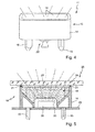
- the operating element 11 for the realization of the operating device 25.
- the operating element 11 has a control element housing 13 with a jacket part 14, which has two mounting feet 15 below.
- a light guide member 16 is arranged in the jacket part 14.
- Underneath is shown diagrammatically an LED 22 for fluoroscopy.
- the light guide part 16 is advantageously designed to generate a luminous symbol in a specific form, which will be described below with reference to FIGS Fig. 6 to 8 will be explained. This can be on the top the optical fiber part 16 a kind of masking, alternatively, a disc of thin material, be applied.
- Fig. 5 is a side section through the operating device 25 quasi a control surface 26 shown.
- an electrically conductive frame 21 made of elastic material, which forms a capacitive sensor element is provided peripherally on the upper side of the operating element 11 or on the outside of the casing part 14.
- the control element 11 acts as a capacitive control element.
- control element 11 is arranged with the mounting feet 15 on a printed circuit board 28, which carries the LED 22 as an SMD LED. This is virtually covered by the control element 11 and can radiate through the light guide member 16 and thus also by the control surface 26 and the hob plate. 2
- an operating element 111 having basically an approximately square basic shape has an annular cutout 123 which is formed on the inside and outside by a cover 123 'on the light guide part in the middle. If an LED illuminates under the operating element 111, then the circular cut-out 123 can be recognized as a light symbol, as shown in FIG Fig. 2 is indicated.
- a control element 211 is shown, in which a hexagonal cutout 223 is provided, which is formed by covers 223 'inside and outside. This corresponds to the quasi Fig. 3 ,
- Fig. 8 is an operating element 311 shown with a luminous symbol in a rectangular shape, formed by a rectangular cutout 323.
- the outer cover 323 ' is a cutout and thus transparent, while the surface of the cutout 323 and the inner cover 323' are opaque. So a maximum large rectangular light symbol can be generated.
Landscapes
- Engineering & Computer Science (AREA)
- Physics & Mathematics (AREA)
- Electromagnetism (AREA)
- Chemical & Material Sciences (AREA)
- Combustion & Propulsion (AREA)
- Mechanical Engineering (AREA)
- General Engineering & Computer Science (AREA)
- Induction Heating Cooking Devices (AREA)
- Electric Stoves And Ranges (AREA)
- Central Heating Systems (AREA)
Abstract
Ein Kochfeld (1) mit einer Kochfeldplatte (2) und einer Vielzahl von Heizeinrichtungen (4), die darunter benachbart zueinander angeordnet sind, weist eine Bedieneinrichtung (25) auf mit einer Bedienfläche (26), Anzeigen (24) und identischen Bedienelementen (11). Die identischen Bedienelemente (11) weisen jeweils ein Bedienelementgehäuse (13) auf mit einem Lichtkanal in lichtundurchlässigem Material du mit einem auf der Oberseite verlaufenden kapazitiven Sensorelement. Eine Anordnung der identischen Bedienelemente (11) in der Bedieneinrichtung (25) entspricht genau einer Anordnung der Heizeinrichtungen (4) unter der Kochfeldplatte (2), und sie bilden zusammen eine Art Anzeige- und Bedienfeld.A hob (1) with a hob plate (2) and a plurality of heaters (4) arranged adjacent to each other has an operating device (25) with an operating surface (26), displays (24) and identical operating elements (11 ). The identical operating elements (11) each have an operating element housing (13) with a light channel in opaque material du with a capacitive sensor element running on top. An arrangement of the identical operating elements (11) in the operating device (25) corresponds exactly to an arrangement of the heating devices (4) under the hob plate (2), and together they form a kind of display and control panel.
Description
Die Erfindung betrifft ein Kochfeld, insbesondere ein Elektrokochfeld, mit einer Kochfeldplatte und mit einer Vielzahl von Heizeinrichtungen und einer Bedieneinrichtung an dem Kochfeld.The invention relates to a hob, in particular an electric hob, with a hob plate and with a plurality of heaters and an operating device on the hob.
Aus der
Für eine Bedieneinrichtung dieser modernen Kochfelder scheinen sogenannten graphischen Touchscreen vorteilhaft. Damit kann an der Bedieneinrichtung auf vielfältige Art und Weise eine Anzeige sowohl von Betriebssituationen bezüglich der beheizten Bereiche bzw. aktivierten Heizeinrichtungen als auch von Leistungs- oder Betriebswerten erfolgen. Ebenso kann eine Bedienperson mittels der darin integrierten Bedienelemente als Berührsensoren die Bedienung vornehmen. Nachteilig an solchen Touchscreens ist deren Temperaturempfindlichkeit, eine hohe Lichtleistung der Rückseitenbeleuchtung, insbesondere bei einer Anordnung unter einer üblicherweise nur schlecht lichtdurchlässigen Glaskeramik-Kochfeldplatte, sowie deren hohe Kosten.For an operating device of these modern cooktops so-called graphical touch screen seem advantageous. This can be done on the operating device in a variety of ways, a display of both operating situations with respect to the heated areas or activated heaters as well as performance or operating values. Likewise, an operator can carry out the operation by means of the operating elements integrated therein as touch sensors. A disadvantage of such touchscreens is their temperature sensitivity, a high light output of the backlight, especially in an arrangement under a usually poorly translucent glass ceramic hob plate, and their high cost.
Der Erfindung liegt die Aufgabe zugrunde, ein eingangs genanntes Kochfeld zu schaffen, mit dem Probleme des Stands der Technik vermieden werden können und es insbesondere möglich ist, eine Bedieneinrichtung eines solchen Kochfelds mit einer Vielzahl von Heizeinrichtungen praxistauglich und komfortabel zu begrenzten Kosten herzustellen.The invention has for its object to provide an aforementioned hob, can be avoided with the problems of the prior art and in particular it is possible to produce a control device of such a hob with a variety of heating practical and convenient to a limited cost.
Gelöst wird diese Aufgabe durch ein Kochfeld mit den Merkmalen des Anspruchs 1. Vorteilhafte sowie bevorzugte Ausgestaltungen der Erfindung sind Gegenstand der weiteren Ansprüche und werden im Folgenden näher erläutert. Der Wortlaut der Ansprüche wird durch ausdrückliche Bezugnahme zum Inhalt der Beschreibung gemacht.This object is achieved by a hob with the features of
Es ist vorgesehen, dass das Kochfeld bzw. Elektrokochfeld eben eine Kochfeldplatte und eine Vielzahl von unter dieser Kochfeldplatte angeordneten Heizeinrichtungen aufweist. Diese Heizeinrichtungen sind benachbart zueinander angeordnet, insbesondere nahezu oder direkt aneinander anliegend, wobei sie mehr als die Hälfte der Fläche der Kochfeldplatte überdecken, vorteilhaft etwa 60% bis 90%. Das Kochfeld weist unter der Kochfeldplatte eine Bedieneinrichtung auf, die Anzeigen und mehrere identische Bedienelemente aufweist, unter Umständen auch noch weitere Bedienelemente. Des Weiteren weist sie eine Bedienfläche auf, unter der die Anzeigen und die identischen Bedienelemente bzw. alle Bedienelemente angeordnet sind. Die Bedienelemente können zusammen eine Art Anzeige- und Bedienfeld bilden.It is envisaged that the hob or electric cooktop just has a cooktop plate and a plurality of arranged under this cooktop plate heaters. These heaters are arranged adjacent to each other, in particular almost or directly adjacent to each other, covering more than half of the surface of the hob plate, advantageously about 60% to 90%. The hob has under the hob plate on a control device that displays and several identical controls, may also have other controls. Furthermore, it has an operating surface, under which the displays and the identical operating elements or all operating elements are arranged. The controls can together form a kind of display and control panel.
Erfindungsgemäß weisen zumindest die identischen Bedienelemente jeweils ein Bedienelementgehäuse auf, welches einen Lichtkanal aufweist, der seitlich von lichtundurchlässigem Material umgeben oder darin integriert ist bzw. zur Seite abgeschirmt ist. Der Lichtkanal kann entweder offen ausgebildet sein oder, alternativ, lichtdurchlässiges bzw. lichtleitendes Material aufweisen, insbesondere als Lichtleitkörper oder -scheibe, insbesondere mit Diffusor- bzw. lichtverteilender Funktion. Oben auf dem Bedienelementgehäuse ist ein kapazitives Sensorelement vorgesehen, das an eine Unterseite der Bedienfläche angelegt ist. Das kapazitive Sensorelement ist vorteilhaft schmal und länglich ausgebildet und verläuft besonders vorteilhaft zumindest entlang von zwei oder drei Seiten des Bedienelementgehäuses, vorzugsweise entlang aller Seiten. Dann ist es abgewinkelt ausgebildet und kann eine Rahmenform aufweisen, wobei es bevorzugt den vorgenannten Lichtkanal nicht überdeckt und maximal mit 1% bis 10% Überdeckung umrahmt. Ein derartiges Sensorelement ist beispielsweise aus der
Dadurch ist es möglich, dass durch eine Anzeigefunktion mittels des Lichtkanals der Bedienelemente einer Bedienperson angezeigt werden kann, welche der Heizeinrichtungen in Betrieb ist, wobei sich hierfür ein Dauerleuchten eignet. Ebenso kann angezeigt werden, welche der Heizeinrichtungen für eine Leistungsveränderung ausgewählt ist, beispielsweise durch Blinken.This makes it possible that can be displayed by a display function by means of the light channel of the controls of an operator, which of the heaters is in operation, which is a permanent lights suitable for this purpose. It can also be displayed which of the heaters is selected for a power change, for example by flashing.
Durch die Funktion der Bedienelemente als Berührsensoren kann auch quasi jede Heizeinrichtung für sich genommen ausgewählt sowie ein- oder ausgeschaltet werden. Des Weiteren ist es möglich, dass eben jeweils Gruppen von Heizeinrichtungen zusammen als eine Art virtuelle Kochstelle je nach Überdeckung durch einen aufgestellten Topf eine Art Berührfläche bilden, die aus mehreren Berührsensoren und somit mehreren Bedienelementen zusammengesetzt ist. An jeder Stelle dieser Fläche kann eine Berührung durch einen darunter angeordneten Berührsensor bzw. ein entsprechendes Bedienelement erkannt werden.As a result of the function of the operating elements as touch sensors, virtually any heating device can be selected on its own and switched on or off. Furthermore, it is possible for groups of heating devices to form together as a kind of virtual hotplate, depending on coverage by an erected pot, a kind of contact surface which is composed of a plurality of touch sensors and thus several control elements. At any point on this surface, a touch can be detected by a touch sensor arranged underneath or a corresponding operating element.
Da eine Aufteilung der Fläche der Kochfeldplatte in beheizte Bereiche nicht feiner ist als in die einzelnen Heizeinrichtungen, wird eben eine Aufteilung der Anzeige auf entsprechende Art und Weise als ausreichend angesehen. So können beispielsweise 5 x 8 bis zu 12 x 20 oder sogar 15 x 25 Heizeinrichtungen vorgesehen sein, also insgesamt 40 bis 240 oder sogar 375 Stück, vorteilhaft etwa 100. Für die reine Anzeige der Heizeinrichtungen bzw. der beheizbaren Fläche des Kochfelds reicht dann eine solche Aufteilung als Auflösung, welche natürlich ganz erheblich unter derjenigen eines üblichen Touch-Displays liegt. Sie wird aber zumindest für die Darstellung der Heizeinrichtungen als ausreichend angesehen und sollte gleichzeitig ausreichend lichtstark sein.Since a division of the surface of the hob plate in heated areas is not finer than in the individual heaters, just a division of the display is considered in a corresponding manner as sufficient. Thus, for example, be provided 5 x 8 up to 12 x 20 or even 15 x 25 heaters, so a total of 40 to 240 or even 375 pieces, advantageously about 100. For the pure display of the heaters or the heated surface of the hob then enough one such a breakdown as a resolution, which of course is considerably lower than that of a conventional touch display. However, it is considered sufficient at least for the representation of the heating devices and should at the same time be sufficiently powerful.
Vorteilhaft ist die Anordnung der identischen Bedienelemente in der Bedieneinrichtung maßstäblich exakt verkleinert als Anordnung der Heizeinrichtungen unter der Kochfeldplatte. Die Verkleinerung kann zwischen 1:3 und 1:20 betragen, vorteilhaft zwischen 1:4 und 1:10.Advantageously, the arrangement of the identical operating elements in the operating device is scaled down exactly to scale as an arrangement of the heaters under the hob plate. The reduction can be between 1: 3 and 1:20, advantageously between 1: 4 and 1:10.
Bei einer bevorzugten Ausgestaltung der Erfindung ist die Bedieneinrichtung im vorderen Bereich des Kochfelds vorgesehen, und zwar entlang der vorderen Seite mittig oder seitlich angeordnet. Dieser Bereich mit der Bedieneinrichtung sollte dann frei von Heizeinrichtungen sein, da zum Einen der Platz benötigt wird und zum Anderen abhängig von der Art der Beheizung zu hohe Temperaturen nahe an der Bedieneinrichtung vermieden werden sollten. Dabei kann bevorzugt auch in der Bedieneinrichtung ein entsprechender Bereich vorne in der Mitte frei bleiben, also die Bedienfläche hier keine zur Darstellung der Heizeinrichtung dienenden Anzeige- bzw. Bedienelemente aufweisen. Andere Bedienelemente bzw. gleiche Bedienelemente für einen anderen Zweck können hier aber vorgesehen sein. So kann beispielsweise in einem vorderen mittleren Bereich der Bedieneinrichtung an der Bedienfläche ein längliches Sensorelement bzw. ein länglicher Sensorelementstreifen vorgesehen sein, der vorteilhaft von links nach rechts verläuft und zur Einstellung einer Leistungsstufe ausgebildet ist. Derartige Sensorelementstreifen sind auch als Slider bekannt aus dem Stand der Technik, siehe beispielsweise die
In weiterer vorteilhafter Ausgestaltung der Erfindung kann die Bedieneinrichtung an der linken und/oder der rechten Seite, also die Menge der identischen Bedienelemente links und/oder rechts einrahmend, mehrere ebenfalls mit einer Leuchtanzeige kombinierte Zusatz-Bedienelemente aufweisen. Diese können für weitere Bedienfunktionen der Bedieneinrichtung ausgebildet und angesteuert sein, beispielsweise Timer-Funktionen, Boost-Funktionen odgl.. Insbesondere können an der Seite auch Leistungsstufen bestimmter virtueller Kochstellen auf der Kochfeldplatte angezeigt werden. Dabei können insgesamt beispielsweise vier bis sechs Leistungsstufenanzeigen vorgesehen sein entsprechend gleich vieler virtueller Kochstellen. Die Leuchtanzeigen können vorteilhaft in Form sogenannter Sieben-Segment-Anzeigen ausgebildet sein, und zwar einstellig oder zweistellig, abhängig von der Anzahl der gewünschten Leistungsstufen sowie eventuell als Anzeigen für Timer-Funktionen. Alternativen sind 23-Segment-Anzeigen entsprechend der
Grundsätzlich können die Heizeinrichtungen sowohl Strahlungsheizeinrichtungen als auch Induktionsheizeinrichtungen sein, evtl. auch Gasheizer, wobei Induktionsheizeinrichtungen bevorzugt werden. Diese weisen nämlich den Vorteil auf, dass sie quasi zwingend eine Topferkennung integriert haben und somit selber erkennen können, ob sie bis zu einem gewünschten vorgegebenen Grad von einem Topf überdeckt werden, also dass sie entsprechend aktiviert oder aktivierbar sind, was dann eben auch an der Anzeige der Bedieneinrichtung dargestellt wird. Dabei sind Ausgestaltungen denkbar, bei denen jede Induktionsheizeinrichtung jeweils eine eigene Leistungsversorgung bzw. eigene Leistungselektronik aufweist. Hierzu wird beispielsweise auf die eingangs genannte
Diese und weitere Merkmale gehen außer aus den Ansprüchen auch aus der Beschreibung und den Zeichnungen hervor, wobei die einzelnen Merkmale jeweils für sich allein oder zu mehreren in Form von Unterkombinationen bei einer Ausführungsform der Erfindung und auf anderen Gebieten verwirklicht sein und vorteilhafte sowie für sich schutzfähige Ausführungen darstellen können, für die hier Schutz beansprucht wird. Die Unterteilung der Anmeldung in einzelne Abschnitte sowie Zwischen-Überschriften beschränken die unter diesen gemachten Aussagen nicht in ihrer Allgemeingültigkeit.These and other features will become apparent from the claims but also from the description and drawings, wherein the individual features each alone or more in the form of sub-combinations in an embodiment of the invention and in other fields be realized and advantageous and protectable Represent embodiments for which protection is claimed here. The subdivision of the application into individual sections as well as intermediate headings does not restrict the general validity of the statements made thereunder.
Ausführungsbeispiele der Erfindung sind in den Zeichnungen schematisch dargestellt und werden im Folgenden näher erläutert. In den Zeichnungen zeigen:
- Fig. 1
- eine Ansicht eines erfindungsgemäßen Kochfelds mit einer Vielzahl von Heizeinrichtungen und einer Bedieneinrichtung,
- Fig. 2
- eine vergrößerte Darstellung einer möglichen Anordnung mehrerer Heizeinrichtungen als Ausschnitt samt zugehöriger Anzeige auf der Bedieneinrichtung,
- Fig. 3
- eine Variation einer Anordnung anders ausgebildeter Heizeinrichtungen samt entsprechender Anzeige auf der Bedieneinrichtung,
- Fig. 4
- eine Schrägansicht auf ein Bedienelement für die Bedieneinrichtung,
- Fig. 5
- eine seitliche Schnittdarstellung durch eine Bedieneinrichtung mit dem Bedienelement aus
Fig. 4 und - Fig. 6
bis 8 - Draufsichten auf verschiedene Ausbildungen der Bedienelemente entsprechend
Fig. 4 mit unterschiedlichen Anzeigen.
- Fig. 1
- a view of a hob according to the invention with a plurality of heaters and a control device,
- Fig. 2
- an enlarged view of a possible arrangement of a plurality of heating devices as a detail and associated display on the operating device,
- Fig. 3
- a variation of an arrangement of differently designed heating devices together with a corresponding display on the operating device,
- Fig. 4
- an oblique view of an operating element for the operating device,
- Fig. 5
- a side sectional view through an operating device with the operating element
Fig. 4 and - Fig. 6 to 8
- Top views of different configurations of the controls accordingly
Fig. 4 with different ads.
In der
Ein freier Bereich 8 ist mittig an der Vorderkante der Kochfeldplatte 2 bzw. des Kochfelds 1 vorgesehen, wo sich keine Heizeinrichtungen 4 befinden. Hier ist eine Bedieneinrichtung 25 angeordnet, vorteilhaft unter derselben Kochfeldplatte 2, die zu diesem Zweck durchgängig und ohne Unterbrechung ausgebildet ist. Die Bedieneinrichtung 25 weist eine Bedienfläche 26 auf, die ihre gesamte Oberfläche bildet. Hier ist die Bedienfläche 26 durch die Kochfeldplatte 2 gebildet bzw. entspricht dieser, so dass die Bedienfläche 26 als ein Bereich der Kochfeldplatte 2 anzusehen ist.A
Den wesentlichen Teil der Bedienfläche 26 bedecken Bedienelemente 11, die hier durch Punkte dargestellt sind, welche leuchtende Symbole sein können. Darauf wird nachgehend noch näher eingegangen. Allerdings leuchten immer nur einige dieser Leuchtsymbole, hier dargestellt im oberen linken Bereich neun Leuchtsymbole, die mit einem gestrichelt dargestellten Kreis 6' entsprechend dem Aufstellort des Topfes 6 gekennzeichnet sind. Es ist zu ersehen, dass ebenso viele Bedienelemente 11 wie Heizeinrichtungen 4 vorgesehen sind, und zwar auch in identischer Anordnung. Aktiviert sind jeweils nur die Leuchtsymbole, bei denen die entsprechenden Heizeinrichtungen 4 in Betrieb sind oder aber zumindest für eine Betriebswahleinstellung ausgewählt sind.The essential part of the
Links und rechts befinden sich an der Bedienfläche 6 drei an sich bekannte Sieben-Segment-Anzeigen 24 übereinander. Dies können auf unterschiedliche Art und Weise realisiert werden, entweder wie aus dem Stand der Technik bekannt mit einem einzigen Gehäuse mit sieben Leuchtbalken bzw. Segmenten darin und jeweils einer LED pro Leuchtbalken. Alternativ können sie auch durch Bauteile ähnlich der Bedienelemente 11 ausgebildet sein, wobei hierfür keine Touch- bzw. Berühr-Funktion vorgesehen ist, und zwar pro Segment eines.Left and right are on the
Im mittleren vorderen Bereich der Bedienfläche 26 ist dort, wo beim Kochfeld 1 der freie Bereich 8 vorgesehen ist, ein Slider 29 als eingangs erläuterter, länglicher Sensorelementstreifen dargestellt. Zu dessen Ausbildung wird auf den vorgenannten Stand der Technik verwiesen. Alternativ kann er ebenfalls aus nachfolgend noch im Detail erläuterten Bedienelementen 11 bestehen, da seine einzelnen Segmente neben der Berühr-Funktion auch eine Anzeige- bzw. Leucht-Funktion haben können und sollten. Dies kann der Fachmann einfach anhand der vorgenannten
In der
In
Entsprechend sind in der
In der
In der
Aus der
In den
In der
In
Claims (14)
wobei eine Bedieneinrichtung an dem Kochfeld und unter der Kochfeldplatte vorgesehen ist mit Anzeigen und mehreren identischen Bedienelementen,
wobei die Bedieneinrichtung eine Bedienfläche aufweist, unter der die Anzeigen und Bedienelemente angeordnet sind,
dadurch gekennzeichnet, dass die identischen Bedienelemente jeweils ein Bedienelementgehäuse aufweisen mit einem Lichtkanal, der seitlich von lichtundurchlässigem Material umgeben ist,
wobei oben auf dem Bedienelementgehäuse ein zumindest entlang zwei oder drei Seiten verlaufendes, schmales längliches kapazitives Sensorelement vorgesehen ist, das an eine Unterseite der Bedienfläche angelegt ist,
wobei eine Anordnung der identischen Bedienelemente in der Bedieneinrichtung einer Anordnung der Heizeinrichtungen unter der Kochfeldplatte entspricht.Hob with a cooktop panel and with a plurality of heaters disposed adjacent to each other under the cooktop panel and covering more than half of the surface of the cooktop panel,
wherein an operating device is provided on the hob and under the hob plate with displays and a plurality of identical operating elements,
wherein the operating device has an operating surface, under which the displays and operating elements are arranged,
characterized in that the identical operating elements each have a control housing with a light channel which is laterally surrounded by opaque material,
wherein a narrow elongate capacitive sensor element extending at least along two or three sides and provided on an underside of the operating surface is provided on top of the control element housing,
wherein an arrangement of the identical operating elements in the operating device corresponds to an arrangement of the heaters under the hob plate.
Priority Applications (1)
| Application Number | Priority Date | Filing Date | Title |
|---|---|---|---|
| PL14174655T PL2837891T3 (en) | 2013-07-03 | 2014-06-27 | Cooktop |
Applications Claiming Priority (1)
| Application Number | Priority Date | Filing Date | Title |
|---|---|---|---|
| DE102013213032.5A DE102013213032A1 (en) | 2013-07-03 | 2013-07-03 | hob |
Publications (3)
| Publication Number | Publication Date |
|---|---|
| EP2837891A2 true EP2837891A2 (en) | 2015-02-18 |
| EP2837891A3 EP2837891A3 (en) | 2015-11-11 |
| EP2837891B1 EP2837891B1 (en) | 2018-12-05 |
Family
ID=51176093
Family Applications (1)
| Application Number | Title | Priority Date | Filing Date |
|---|---|---|---|
| EP14174655.2A Active EP2837891B1 (en) | 2013-07-03 | 2014-06-27 | Cooktop |
Country Status (4)
| Country | Link |
|---|---|
| EP (1) | EP2837891B1 (en) |
| DE (1) | DE102013213032A1 (en) |
| ES (1) | ES2711665T3 (en) |
| PL (1) | PL2837891T3 (en) |
Cited By (1)
| Publication number | Priority date | Publication date | Assignee | Title |
|---|---|---|---|---|
| EP2980488B1 (en) | 2014-07-31 | 2017-09-13 | BSH Hausgeräte GmbH | Cooking hob with an illuminated connection display area |
Families Citing this family (4)
| Publication number | Priority date | Publication date | Assignee | Title |
|---|---|---|---|---|
| EP3130858B1 (en) * | 2015-08-11 | 2022-03-16 | Electrolux Appliances Aktiebolag | Cooking hob |
| DE102016225459B4 (en) * | 2016-12-19 | 2019-12-05 | E.G.O. Elektro-Gerätebau GmbH | Hob and method for operating a hob |
| EP3401605B1 (en) | 2017-05-12 | 2024-02-21 | Electrolux Appliances Aktiebolag | Cooking hob with user interface |
| DE102020210559B4 (en) | 2020-08-20 | 2022-03-31 | E.G.O. Elektro-Gerätebau GmbH | Operating device for a household appliance, household appliance and method for displaying information on a household appliance |
Citations (5)
| Publication number | Priority date | Publication date | Assignee | Title |
|---|---|---|---|---|
| EP1206164A2 (en) | 2000-11-08 | 2002-05-15 | Whirlpool Corporation | Device for determining the location of cooking utensils on a cooking hob comprising discrete distributed heating elements |
| EP1463383A1 (en) | 2003-03-27 | 2004-09-29 | E.G.O. Elektro-Gerätebau GmbH | Heating device for a flat heating with induction heating elements |
| DE102004044355A1 (en) | 2004-09-09 | 2006-03-30 | E.G.O. Elektro-Gerätebau GmbH | Method for optically marking a touch switch and such a touch switch |
| DE102011006021A1 (en) | 2011-03-24 | 2012-09-27 | E.G.O. Elektro-Gerätebau GmbH | Operating device for an electrical appliance |
| DE102012010321A1 (en) | 2012-05-21 | 2013-11-21 | E.G.O. Elektro-Gerätebau GmbH | Sensor element device for a capacitive touch switch an operating device, operating device and hob |
Family Cites Families (11)
| Publication number | Priority date | Publication date | Assignee | Title |
|---|---|---|---|---|
| ES2170033B1 (en) * | 2000-12-26 | 2003-11-01 | Bsh Balay Sa | INDUCTION COOKING HOB |
| ITMI20031602A1 (en) * | 2003-08-04 | 2005-02-05 | Whirlpool Co | COOKING PLAN WITH RANDOM PLACING WITH USER INTERFACE |
| DE102008029567A1 (en) * | 2008-06-21 | 2010-01-07 | Preh Gmbh | Illuminated capacitive proximity sensor |
| DE102009036161B4 (en) * | 2009-07-28 | 2017-01-12 | E.G.O. Elektro-Gerätebau GmbH | Sensor element device and method for producing a sensor element device |
| WO2011020721A1 (en) * | 2009-08-17 | 2011-02-24 | BSH Bosch und Siemens Hausgeräte GmbH | Method for producing a domestic appliance cover panel |
| KR20110136226A (en) * | 2010-06-14 | 2011-12-21 | 삼성전자주식회사 | Induction heating cooker and control method therof |
| FR2966004B1 (en) * | 2010-10-07 | 2012-11-09 | Fagorbrandt Sas | METHOD FOR OPERATING CONTROL OF INDUCTOR ASSEMBLY OF INDUCTION COOKTOP AND INDUCTION COOKTOP THEREFOR |
| EP2506674B1 (en) * | 2011-03-26 | 2016-08-10 | Electrolux Home Products Corporation N.V. | An induction cooking hob with a pot detection device |
| FR2978530B1 (en) * | 2011-07-26 | 2013-08-02 | Fagorbrandt Sas | COOKTOP AND METHOD FOR CONTROLLING THE OPERATION OF A COOKTOP |
| DE102011087217A1 (en) * | 2011-11-28 | 2013-05-29 | BSH Bosch und Siemens Hausgeräte GmbH | Operating device for adjusting working conditions of hob that is built into worktop of kitchenette, has control unit for releasing, activating or inhibiting functions of electrical appliance based on toggle recognition |
| ES2439418B1 (en) * | 2012-07-20 | 2015-03-12 | Bsh Electrodomesticos Espana | Cooking Field Device |
-
2013
- 2013-07-03 DE DE102013213032.5A patent/DE102013213032A1/en not_active Withdrawn
-
2014
- 2014-06-27 PL PL14174655T patent/PL2837891T3/en unknown
- 2014-06-27 EP EP14174655.2A patent/EP2837891B1/en active Active
- 2014-06-27 ES ES14174655T patent/ES2711665T3/en active Active
Patent Citations (5)
| Publication number | Priority date | Publication date | Assignee | Title |
|---|---|---|---|---|
| EP1206164A2 (en) | 2000-11-08 | 2002-05-15 | Whirlpool Corporation | Device for determining the location of cooking utensils on a cooking hob comprising discrete distributed heating elements |
| EP1463383A1 (en) | 2003-03-27 | 2004-09-29 | E.G.O. Elektro-Gerätebau GmbH | Heating device for a flat heating with induction heating elements |
| DE102004044355A1 (en) | 2004-09-09 | 2006-03-30 | E.G.O. Elektro-Gerätebau GmbH | Method for optically marking a touch switch and such a touch switch |
| DE102011006021A1 (en) | 2011-03-24 | 2012-09-27 | E.G.O. Elektro-Gerätebau GmbH | Operating device for an electrical appliance |
| DE102012010321A1 (en) | 2012-05-21 | 2013-11-21 | E.G.O. Elektro-Gerätebau GmbH | Sensor element device for a capacitive touch switch an operating device, operating device and hob |
Cited By (1)
| Publication number | Priority date | Publication date | Assignee | Title |
|---|---|---|---|---|
| EP2980488B1 (en) | 2014-07-31 | 2017-09-13 | BSH Hausgeräte GmbH | Cooking hob with an illuminated connection display area |
Also Published As
| Publication number | Publication date |
|---|---|
| DE102013213032A1 (en) | 2015-01-08 |
| EP2837891B1 (en) | 2018-12-05 |
| EP2837891A3 (en) | 2015-11-11 |
| PL2837891T3 (en) | 2019-05-31 |
| ES2711665T3 (en) | 2019-05-06 |
Similar Documents
| Publication | Publication Date | Title |
|---|---|---|
| DE102007057076B4 (en) | Hob and method for operating a hob | |
| EP2837891B1 (en) | Cooktop | |
| EP2141415A2 (en) | Display device for a cooking hob, cooking hob and method for operating such a display device | |
| EP2290820B1 (en) | Method for inputting a two-digit value at an operating device | |
| EP2689191B1 (en) | Operating device for an electric device | |
| WO2014170161A1 (en) | Stove top having a cooking zone and a reduced symbol depiction in the cooking zone in a display unit and method for operating a stove top | |
| EP3490339A1 (en) | Induction cooking hob and pot detection sensor for an induction cooking hob | |
| EP3537049B1 (en) | Cooking hob and method for providing a display on the cooking hob | |
| EP1418384B1 (en) | Display device with lighting assembly for an electrical household appliance | |
| EP2224174A2 (en) | Steam extractor and operating method therefor | |
| EP3232428B1 (en) | Display element, display device with such a display element and electric device with such a display device | |
| EP3330617A1 (en) | Hob and method for operating same | |
| DE3446195C2 (en) | ||
| DE102016225459B4 (en) | Hob and method for operating a hob | |
| DE3621436C2 (en) | ||
| DE102013206867B4 (en) | Operating device for an electrical appliance and electrical appliance | |
| DE3603324C2 (en) | ||
| DE10240147A1 (en) | Hob with barrier for cooking has cooking field and service field of same material | |
| DE3621438A1 (en) | Control and display device for domestic appliances | |
| DE102016223849B3 (en) | Hob and method of operating such a hob | |
| DE102017207598A1 (en) | Display device for a hob, hob and operating method on such a hob | |
| DE202010006890U1 (en) | Operating device for a hob | |
| DE102018204009B4 (en) | Method of operating an electric cooking device and electric cooking device | |
| EP0982972B1 (en) | Switching device in an heating apparatus | |
| DE19810438A1 (en) | Cooker |
Legal Events
| Date | Code | Title | Description |
|---|---|---|---|
| 17P | Request for examination filed |
Effective date: 20140627 |
|
| AK | Designated contracting states |
Kind code of ref document: A2 Designated state(s): AL AT BE BG CH CY CZ DE DK EE ES FI FR GB GR HR HU IE IS IT LI LT LU LV MC MK MT NL NO PL PT RO RS SE SI SK SM TR |
|
| AX | Request for extension of the european patent |
Extension state: BA ME |
|
| PUAI | Public reference made under article 153(3) epc to a published international application that has entered the european phase |
Free format text: ORIGINAL CODE: 0009012 |
|
| PUAL | Search report despatched |
Free format text: ORIGINAL CODE: 0009013 |
|
| AK | Designated contracting states |
Kind code of ref document: A3 Designated state(s): AL AT BE BG CH CY CZ DE DK EE ES FI FR GB GR HR HU IE IS IT LI LT LU LV MC MK MT NL NO PL PT RO RS SE SI SK SM TR |
|
| AX | Request for extension of the european patent |
Extension state: BA ME |
|
| RIC1 | Information provided on ipc code assigned before grant |
Ipc: F24C 7/08 20060101AFI20151002BHEP |
|
| R17P | Request for examination filed (corrected) |
Effective date: 20160511 |
|
| RBV | Designated contracting states (corrected) |
Designated state(s): AL AT BE BG CH CY CZ DE DK EE ES FI FR GB GR HR HU IE IS IT LI LT LU LV MC MK MT NL NO PL PT RO RS SE SI SK SM TR |
|
| STAA | Information on the status of an ep patent application or granted ep patent |
Free format text: STATUS: EXAMINATION IS IN PROGRESS |
|
| 17Q | First examination report despatched |
Effective date: 20161110 |
|
| GRAP | Despatch of communication of intention to grant a patent |
Free format text: ORIGINAL CODE: EPIDOSNIGR1 |
|
| STAA | Information on the status of an ep patent application or granted ep patent |
Free format text: STATUS: GRANT OF PATENT IS INTENDED |
|
| RIC1 | Information provided on ipc code assigned before grant |
Ipc: H05B 6/12 20060101ALI20180604BHEP Ipc: F24C 7/08 20060101AFI20180604BHEP |
|
| INTG | Intention to grant announced |
Effective date: 20180622 |
|
| GRAS | Grant fee paid |
Free format text: ORIGINAL CODE: EPIDOSNIGR3 |
|
| GRAA | (expected) grant |
Free format text: ORIGINAL CODE: 0009210 |
|
| STAA | Information on the status of an ep patent application or granted ep patent |
Free format text: STATUS: THE PATENT HAS BEEN GRANTED |
|
| AK | Designated contracting states |
Kind code of ref document: B1 Designated state(s): AL AT BE BG CH CY CZ DE DK EE ES FI FR GB GR HR HU IE IS IT LI LT LU LV MC MK MT NL NO PL PT RO RS SE SI SK SM TR |
|
| REG | Reference to a national code |
Ref country code: GB Ref legal event code: FG4D Free format text: NOT ENGLISH |
|
| REG | Reference to a national code |
Ref country code: CH Ref legal event code: EP |
|
| REG | Reference to a national code |
Ref country code: AT Ref legal event code: REF Ref document number: 1073541 Country of ref document: AT Kind code of ref document: T Effective date: 20181215 |
|
| REG | Reference to a national code |
Ref country code: IE Ref legal event code: FG4D Free format text: LANGUAGE OF EP DOCUMENT: GERMAN |
|
| REG | Reference to a national code |
Ref country code: DE Ref legal event code: R096 Ref document number: 502014010250 Country of ref document: DE |
|
| REG | Reference to a national code |
Ref country code: NL Ref legal event code: MP Effective date: 20181205 |
|
| REG | Reference to a national code |
Ref country code: LT Ref legal event code: MG4D |
|
| PG25 | Lapsed in a contracting state [announced via postgrant information from national office to epo] |
Ref country code: BG Free format text: LAPSE BECAUSE OF FAILURE TO SUBMIT A TRANSLATION OF THE DESCRIPTION OR TO PAY THE FEE WITHIN THE PRESCRIBED TIME-LIMIT Effective date: 20190305 Ref country code: LT Free format text: LAPSE BECAUSE OF FAILURE TO SUBMIT A TRANSLATION OF THE DESCRIPTION OR TO PAY THE FEE WITHIN THE PRESCRIBED TIME-LIMIT Effective date: 20181205 Ref country code: HR Free format text: LAPSE BECAUSE OF FAILURE TO SUBMIT A TRANSLATION OF THE DESCRIPTION OR TO PAY THE FEE WITHIN THE PRESCRIBED TIME-LIMIT Effective date: 20181205 Ref country code: NO Free format text: LAPSE BECAUSE OF FAILURE TO SUBMIT A TRANSLATION OF THE DESCRIPTION OR TO PAY THE FEE WITHIN THE PRESCRIBED TIME-LIMIT Effective date: 20190305 Ref country code: LV Free format text: LAPSE BECAUSE OF FAILURE TO SUBMIT A TRANSLATION OF THE DESCRIPTION OR TO PAY THE FEE WITHIN THE PRESCRIBED TIME-LIMIT Effective date: 20181205 Ref country code: FI Free format text: LAPSE BECAUSE OF FAILURE TO SUBMIT A TRANSLATION OF THE DESCRIPTION OR TO PAY THE FEE WITHIN THE PRESCRIBED TIME-LIMIT Effective date: 20181205 |
|
| REG | Reference to a national code |
Ref country code: ES Ref legal event code: FG2A Ref document number: 2711665 Country of ref document: ES Kind code of ref document: T3 Effective date: 20190506 |
|
| PG25 | Lapsed in a contracting state [announced via postgrant information from national office to epo] |
Ref country code: AL Free format text: LAPSE BECAUSE OF FAILURE TO SUBMIT A TRANSLATION OF THE DESCRIPTION OR TO PAY THE FEE WITHIN THE PRESCRIBED TIME-LIMIT Effective date: 20181205 Ref country code: SE Free format text: LAPSE BECAUSE OF FAILURE TO SUBMIT A TRANSLATION OF THE DESCRIPTION OR TO PAY THE FEE WITHIN THE PRESCRIBED TIME-LIMIT Effective date: 20181205 Ref country code: RS Free format text: LAPSE BECAUSE OF FAILURE TO SUBMIT A TRANSLATION OF THE DESCRIPTION OR TO PAY THE FEE WITHIN THE PRESCRIBED TIME-LIMIT Effective date: 20181205 Ref country code: GR Free format text: LAPSE BECAUSE OF FAILURE TO SUBMIT A TRANSLATION OF THE DESCRIPTION OR TO PAY THE FEE WITHIN THE PRESCRIBED TIME-LIMIT Effective date: 20190306 |
|
| PG25 | Lapsed in a contracting state [announced via postgrant information from national office to epo] |
Ref country code: NL Free format text: LAPSE BECAUSE OF FAILURE TO SUBMIT A TRANSLATION OF THE DESCRIPTION OR TO PAY THE FEE WITHIN THE PRESCRIBED TIME-LIMIT Effective date: 20181205 |
|
| PG25 | Lapsed in a contracting state [announced via postgrant information from national office to epo] |
Ref country code: PT Free format text: LAPSE BECAUSE OF FAILURE TO SUBMIT A TRANSLATION OF THE DESCRIPTION OR TO PAY THE FEE WITHIN THE PRESCRIBED TIME-LIMIT Effective date: 20190405 Ref country code: CZ Free format text: LAPSE BECAUSE OF FAILURE TO SUBMIT A TRANSLATION OF THE DESCRIPTION OR TO PAY THE FEE WITHIN THE PRESCRIBED TIME-LIMIT Effective date: 20181205 Ref country code: IT Free format text: LAPSE BECAUSE OF FAILURE TO SUBMIT A TRANSLATION OF THE DESCRIPTION OR TO PAY THE FEE WITHIN THE PRESCRIBED TIME-LIMIT Effective date: 20181205 |
|
| PG25 | Lapsed in a contracting state [announced via postgrant information from national office to epo] |
Ref country code: SM Free format text: LAPSE BECAUSE OF FAILURE TO SUBMIT A TRANSLATION OF THE DESCRIPTION OR TO PAY THE FEE WITHIN THE PRESCRIBED TIME-LIMIT Effective date: 20181205 Ref country code: EE Free format text: LAPSE BECAUSE OF FAILURE TO SUBMIT A TRANSLATION OF THE DESCRIPTION OR TO PAY THE FEE WITHIN THE PRESCRIBED TIME-LIMIT Effective date: 20181205 Ref country code: IS Free format text: LAPSE BECAUSE OF FAILURE TO SUBMIT A TRANSLATION OF THE DESCRIPTION OR TO PAY THE FEE WITHIN THE PRESCRIBED TIME-LIMIT Effective date: 20190405 Ref country code: SK Free format text: LAPSE BECAUSE OF FAILURE TO SUBMIT A TRANSLATION OF THE DESCRIPTION OR TO PAY THE FEE WITHIN THE PRESCRIBED TIME-LIMIT Effective date: 20181205 Ref country code: RO Free format text: LAPSE BECAUSE OF FAILURE TO SUBMIT A TRANSLATION OF THE DESCRIPTION OR TO PAY THE FEE WITHIN THE PRESCRIBED TIME-LIMIT Effective date: 20181205 |
|
| REG | Reference to a national code |
Ref country code: DE Ref legal event code: R097 Ref document number: 502014010250 Country of ref document: DE |
|
| PLBE | No opposition filed within time limit |
Free format text: ORIGINAL CODE: 0009261 |
|
| STAA | Information on the status of an ep patent application or granted ep patent |
Free format text: STATUS: NO OPPOSITION FILED WITHIN TIME LIMIT |
|
| PG25 | Lapsed in a contracting state [announced via postgrant information from national office to epo] |
Ref country code: SI Free format text: LAPSE BECAUSE OF FAILURE TO SUBMIT A TRANSLATION OF THE DESCRIPTION OR TO PAY THE FEE WITHIN THE PRESCRIBED TIME-LIMIT Effective date: 20181205 Ref country code: DK Free format text: LAPSE BECAUSE OF FAILURE TO SUBMIT A TRANSLATION OF THE DESCRIPTION OR TO PAY THE FEE WITHIN THE PRESCRIBED TIME-LIMIT Effective date: 20181205 |
|
| 26N | No opposition filed |
Effective date: 20190906 |
|
| PG25 | Lapsed in a contracting state [announced via postgrant information from national office to epo] |
Ref country code: MC Free format text: LAPSE BECAUSE OF FAILURE TO SUBMIT A TRANSLATION OF THE DESCRIPTION OR TO PAY THE FEE WITHIN THE PRESCRIBED TIME-LIMIT Effective date: 20181205 |
|
| REG | Reference to a national code |
Ref country code: CH Ref legal event code: PL |
|
| GBPC | Gb: european patent ceased through non-payment of renewal fee |
Effective date: 20190627 |
|
| REG | Reference to a national code |
Ref country code: BE Ref legal event code: MM Effective date: 20190630 |
|
| PG25 | Lapsed in a contracting state [announced via postgrant information from national office to epo] |
Ref country code: TR Free format text: LAPSE BECAUSE OF FAILURE TO SUBMIT A TRANSLATION OF THE DESCRIPTION OR TO PAY THE FEE WITHIN THE PRESCRIBED TIME-LIMIT Effective date: 20181205 |
|
| PG25 | Lapsed in a contracting state [announced via postgrant information from national office to epo] |
Ref country code: GB Free format text: LAPSE BECAUSE OF NON-PAYMENT OF DUE FEES Effective date: 20190627 Ref country code: IE Free format text: LAPSE BECAUSE OF NON-PAYMENT OF DUE FEES Effective date: 20190627 |
|
| PG25 | Lapsed in a contracting state [announced via postgrant information from national office to epo] |
Ref country code: CH Free format text: LAPSE BECAUSE OF NON-PAYMENT OF DUE FEES Effective date: 20190630 Ref country code: LI Free format text: LAPSE BECAUSE OF NON-PAYMENT OF DUE FEES Effective date: 20190630 Ref country code: LU Free format text: LAPSE BECAUSE OF NON-PAYMENT OF DUE FEES Effective date: 20190627 Ref country code: BE Free format text: LAPSE BECAUSE OF NON-PAYMENT OF DUE FEES Effective date: 20190630 |
|
| REG | Reference to a national code |
Ref country code: AT Ref legal event code: MM01 Ref document number: 1073541 Country of ref document: AT Kind code of ref document: T Effective date: 20190627 |
|
| PG25 | Lapsed in a contracting state [announced via postgrant information from national office to epo] |
Ref country code: AT Free format text: LAPSE BECAUSE OF NON-PAYMENT OF DUE FEES Effective date: 20190627 |
|
| PG25 | Lapsed in a contracting state [announced via postgrant information from national office to epo] |
Ref country code: CY Free format text: LAPSE BECAUSE OF FAILURE TO SUBMIT A TRANSLATION OF THE DESCRIPTION OR TO PAY THE FEE WITHIN THE PRESCRIBED TIME-LIMIT Effective date: 20181205 |
|
| PG25 | Lapsed in a contracting state [announced via postgrant information from national office to epo] |
Ref country code: HU Free format text: LAPSE BECAUSE OF FAILURE TO SUBMIT A TRANSLATION OF THE DESCRIPTION OR TO PAY THE FEE WITHIN THE PRESCRIBED TIME-LIMIT; INVALID AB INITIO Effective date: 20140627 Ref country code: MT Free format text: LAPSE BECAUSE OF FAILURE TO SUBMIT A TRANSLATION OF THE DESCRIPTION OR TO PAY THE FEE WITHIN THE PRESCRIBED TIME-LIMIT Effective date: 20181205 |
|
| PGFP | Annual fee paid to national office [announced via postgrant information from national office to epo] |
Ref country code: DE Payment date: 20210624 Year of fee payment: 8 Ref country code: FR Payment date: 20210622 Year of fee payment: 8 |
|
| PGFP | Annual fee paid to national office [announced via postgrant information from national office to epo] |
Ref country code: PL Payment date: 20210527 Year of fee payment: 8 |
|
| PGFP | Annual fee paid to national office [announced via postgrant information from national office to epo] |
Ref country code: ES Payment date: 20210722 Year of fee payment: 8 |
|
| PG25 | Lapsed in a contracting state [announced via postgrant information from national office to epo] |
Ref country code: MK Free format text: LAPSE BECAUSE OF FAILURE TO SUBMIT A TRANSLATION OF THE DESCRIPTION OR TO PAY THE FEE WITHIN THE PRESCRIBED TIME-LIMIT Effective date: 20181205 |
|
| REG | Reference to a national code |
Ref country code: DE Ref legal event code: R119 Ref document number: 502014010250 Country of ref document: DE |
|
| PG25 | Lapsed in a contracting state [announced via postgrant information from national office to epo] |
Ref country code: FR Free format text: LAPSE BECAUSE OF NON-PAYMENT OF DUE FEES Effective date: 20220630 |
|
| PG25 | Lapsed in a contracting state [announced via postgrant information from national office to epo] |
Ref country code: DE Free format text: LAPSE BECAUSE OF NON-PAYMENT OF DUE FEES Effective date: 20230103 |
|
| REG | Reference to a national code |
Ref country code: ES Ref legal event code: FD2A Effective date: 20230804 |
|
| PG25 | Lapsed in a contracting state [announced via postgrant information from national office to epo] |
Ref country code: ES Free format text: LAPSE BECAUSE OF NON-PAYMENT OF DUE FEES Effective date: 20220628 |