EP3145040B1 - Câbles comprenant un point de connexion - Google Patents
Câbles comprenant un point de connexion Download PDFInfo
- Publication number
- EP3145040B1 EP3145040B1 EP16188923.3A EP16188923A EP3145040B1 EP 3145040 B1 EP3145040 B1 EP 3145040B1 EP 16188923 A EP16188923 A EP 16188923A EP 3145040 B1 EP3145040 B1 EP 3145040B1
- Authority
- EP
- European Patent Office
- Prior art keywords
- encapsulation
- contact carrier
- connection point
- connector part
- housing
- Prior art date
- Legal status (The legal status is an assumption and is not a legal conclusion. Google has not performed a legal analysis and makes no representation as to the accuracy of the status listed.)
- Active
Links
- 238000005538 encapsulation Methods 0.000 claims description 55
- 239000004020 conductor Substances 0.000 claims description 44
- 238000007789 sealing Methods 0.000 claims description 9
- 239000000470 constituent Substances 0.000 claims 2
- 239000000463 material Substances 0.000 description 10
- 230000005540 biological transmission Effects 0.000 description 6
- 238000002788 crimping Methods 0.000 description 6
- 238000001746 injection moulding Methods 0.000 description 5
- 238000004519 manufacturing process Methods 0.000 description 5
- 230000007613 environmental effect Effects 0.000 description 4
- 238000000034 method Methods 0.000 description 4
- 239000003921 oil Substances 0.000 description 4
- 238000000926 separation method Methods 0.000 description 3
- 238000005266 casting Methods 0.000 description 2
- 238000010276 construction Methods 0.000 description 2
- 238000002347 injection Methods 0.000 description 2
- 239000007924 injection Substances 0.000 description 2
- 229910000679 solder Inorganic materials 0.000 description 2
- 239000012080 ambient air Substances 0.000 description 1
- 238000005452 bending Methods 0.000 description 1
- 230000000694 effects Effects 0.000 description 1
- 238000007765 extrusion coating Methods 0.000 description 1
- 239000012208 gear oil Substances 0.000 description 1
- 238000009434 installation Methods 0.000 description 1
- 239000000203 mixture Substances 0.000 description 1
- 230000003287 optical effect Effects 0.000 description 1
- 238000003825 pressing Methods 0.000 description 1
- 239000007779 soft material Substances 0.000 description 1
- 239000000243 solution Substances 0.000 description 1
Images


Classifications
-
- B—PERFORMING OPERATIONS; TRANSPORTING
- B60—VEHICLES IN GENERAL
- B60R—VEHICLES, VEHICLE FITTINGS, OR VEHICLE PARTS, NOT OTHERWISE PROVIDED FOR
- B60R16/00—Electric or fluid circuits specially adapted for vehicles and not otherwise provided for; Arrangement of elements of electric or fluid circuits specially adapted for vehicles and not otherwise provided for
- B60R16/02—Electric or fluid circuits specially adapted for vehicles and not otherwise provided for; Arrangement of elements of electric or fluid circuits specially adapted for vehicles and not otherwise provided for electric constitutive elements
- B60R16/0207—Wire harnesses
- B60R16/0215—Protecting, fastening and routing means therefor
- B60R16/0222—Grommets
-
- H—ELECTRICITY
- H02—GENERATION; CONVERSION OR DISTRIBUTION OF ELECTRIC POWER
- H02G—INSTALLATION OF ELECTRIC CABLES OR LINES, OR OF COMBINED OPTICAL AND ELECTRIC CABLES OR LINES
- H02G15/00—Cable fittings
- H02G15/08—Cable junctions
-
- H—ELECTRICITY
- H02—GENERATION; CONVERSION OR DISTRIBUTION OF ELECTRIC POWER
- H02G—INSTALLATION OF ELECTRIC CABLES OR LINES, OR OF COMBINED OPTICAL AND ELECTRIC CABLES OR LINES
- H02G1/00—Methods or apparatus specially adapted for installing, maintaining, repairing or dismantling electric cables or lines
- H02G1/14—Methods or apparatus specially adapted for installing, maintaining, repairing or dismantling electric cables or lines for joining or terminating cables
-
- H—ELECTRICITY
- H02—GENERATION; CONVERSION OR DISTRIBUTION OF ELECTRIC POWER
- H02G—INSTALLATION OF ELECTRIC CABLES OR LINES, OR OF COMBINED OPTICAL AND ELECTRIC CABLES OR LINES
- H02G3/00—Installations of electric cables or lines or protective tubing therefor in or on buildings, equivalent structures or vehicles
- H02G3/22—Installations of cables or lines through walls, floors or ceilings, e.g. into buildings
Definitions
- the invention relates to a wiring harness with a connection point according to the preamble of claim 1, as shown in EP2763242A known.
- a sensor of an operating parameter of a vehicle is to be recorded with a sensor, which is connected via cables to a control unit, wherein the recorded operating parameters are transmitted by means of the cable.
- the one unit such as sensor, actuator or the like
- These units are often arranged in areas where significantly different environmental conditions prevail, as in the rest of the vehicle.
- an oil pressure or oil temperature sensor in a transmission housing or in an oil sump of a vehicle in which high pressures and / or significantly higher temperatures prevail during operation of the vehicle than in the remaining environment in which the vehicle is located. Therefore, it is necessary to provide a connection point with which the wiring harness between the one unit and the control unit can be performed, for example, by a housing, the location of performance being the separation between the two distinctly different environmental parameters. In this case, it is absolutely necessary to establish a seal in the region of this parting plane (for example between the interior of a gearbox of a vehicle and the outside around the gearbox) in order to avoid that the two different ambient conditions (inside hot gear oil, outside cooler ambient air) mix.
- this parting plane for example between the interior of a gearbox of a vehicle and the outside around the gearbox
- the invention has for its object to provide a wiring harness with a connection point for passage through a housing, with which the above-described requirements are met.
- a wiring harness having a connection point with the features of claim 1, suitable and designed to connect at least two electrical conductors together and lead through a parting plane, prevailing on both sides of the parting plane from each other different environmental conditions, wherein at one End of an electrical conductor arranged a connector part and a contact carrier is provided which receives at least the one connector part, wherein the further electrical conductor is contacted with the connector part.
- the use of the contact carrier has the advantage that it can be precisely adapted to the geometric conditions of the opening in the housing through which the electrical conductors are to be performed. This means that it is adapted to the opening in the housing with respect to its outer geometries, not only to arrange it there, but also permanently in its position and above all to seal.
- the contact carrier on the one hand ensures the seal against the housing, through which the electrical conductor, more precisely a cable with electrical conductors to be performed.
- an interface is also implemented with it in order to be able to form the electrical conductors or the cables which are to be carried out by it on both sides of the parting line to the respective requirements.
- the contact carrier forms a receptacle for at least one connector part which is suitable and designed to connect the at least two electrical conductors (the at least one electrical conductor outside the housing and the at least one electrical conductor inside the housing) to one another.
- the connector part can be contacted with the two electrical conductors to be connected and subsequently the contact carrier can be realized as encapsulation (injection-molded part, cast part or the like). This variant will be described further below.
- the contact carrier is sealingly inserted into the separation point.
- the contact carrier is positively inserted into the opening.
- the outer geometry of the contact carrier is slightly larger than the inner geometry of the opening, so that the seal by positive engagement, for example by means of pressing the contact carrier, takes place.
- a sealing element for sealing is an integral part of the contact carrier. In the latter case, for example, the manufacture of the contact carrier in a two-component casting or injection molding process is contemplated using two materials.
- the main body of the contact carrier is made of a comparatively hard material and the areas of the contact carrier, which are to take over the sealing function, are made of a comparatively soft material compared to.
- the electrical conductor is sealingly inserted into the contact carrier. This is realized either by the fact that the at least one electrical conductor, which is connected to the connector part, is overmolded, wherein the encapsulation forms the contact carrier.
- a plurality of electrical conductors are encapsulated in an encapsulation process to form the common contact carrier.
- the at least one electrical conductor is that conductor which, starting from the separating plane, is oriented in the direction of the interior of the housing.
- At least the contact region in which the further electrical conductor is contacted with the connector part is provided with an encapsulation.
- This encapsulation adjoins the contact carrier, preferably in that direction out of the housing with the parting plane. This means that in a preferred embodiment, this encapsulation is arranged completely outside the housing. However, it can also be thought that this encapsulation not only comes to rest on an end face of the contact carrier, in particular sealingly, but also encloses an end region of the contact carrier which points outward from the parting plane.
- the encapsulation can be realized as a further encapsulation if the contact carrier has been produced either as an independent component beforehand in an injection molding process or if the at least one connector part has been encapsulated with the electrical conductor arranged thereon.
- This further encapsulation summarizes the outwardly guided electrical conductors and protects the contact region of the at least one connector part, on which the further (outwardly guided) further electrical conductor is arranged and electrically contacted.
- this further encapsulation is arranged completely outside the housing and only adjoins the parting plane, but alternatively it can also be thought to arrange this further encapsulation in a partial region of the opening.
- the further encapsulation has at least one latching hook, a locking clip or the like.
- the finished connection point is preferably fixed to the region of the opening in the parting plane, so that it is avoided that the connection point can move into the interior of the housing.
- the contact carrier has at least one latching hook with which it engages behind the parting plane for the purpose of fixing it.
- the at least one latching hook preferably two opposing latching hooks, engages behind a corresponding geometry around the opening in the housing, behind the parting plane.
- the connector part has a projection for the purpose of its attachment to the contract carrier.
- the connector part is, for example, a stamped part which has contact areas for the fixing and contacting of the electrical conductors to be connected to one another at its two ends.
- the one end of the connector part is designed for the crimped contacting, whereas the other end is lance-like, there to solder the end of the associated electrical conductor to weld or the like.
- the projection for example as a resilient tab, is formed, which then engages behind a corresponding geometry within the contact chamber of the contact carrier (if it is designed as an independent component).
- a projection may also be present, but need not. If the projection of the connector part is present in the case of the encapsulation for configuring the contact carrier, it advantageously has the effect that the connector part can not be rotated within the encapsulation.
- the invention provides a cable set which has a connection point for passage through a housing, in which two encapsulations are provided in the region of the connection point, wherein a first cable and a second cable led out of the one encapsulation from the one encapsulation is, wherein the one cable is disposed within the housing and the second cable outside the housing and each electrical conductor of a cable in the region of the connection point via a connector part connected to each other and electrically contacted.
- each cable to the requirements inside or outside of the housing also with regard to its choice of material, in particular the outer jacket can be adjusted.
- the two encapsulations also have the advantage that the geometry, in particular an external geometry, can be given to them during the encapsulation process, which is adapted to the respective installation location. For example, it can be ensured with the one encapsulation which is arranged inside the housing that the connection point can be securely and permanently fixed to the housing, in particular its passage opening for the connection point.
- an angling that is, cable guide or the like can be realized.
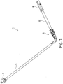
- FIGS. 1 to 8 An embodiment is in the FIGS. 1 to 8 shown, from which also emerge the individual steps of the production of such a wiring harness.
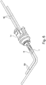
- the reference numeral 1 denotes a line set, which has a connection point 2.
- a connector 3, 4 is arranged, which is only an example and the ends of the cable for further assembly can remain free or z. B, are soldered directly to a board of a control unit.
- a first cable 5 in the direction of the connector 3 and a further cable 6 in the direction of the connector 4 is arranged.
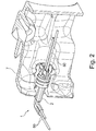
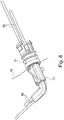
- FIG. 2 shows the exemplary arrangement of the joint 2 in a housing 7, for example in a transmission housing or the like.
- the cable set 1 is performed by a correspondingly shaped opening in the housing 7, wherein the cable 5 (shown here with two electrical conductors 50, only by way of example) outside and the cable 6, also exemplified here with two electrical conductors 60 , is disposed within the housing 7.
- the housing 7 there are normal ambient conditions (eg normal outside temperature) and within the housing 7 significantly different environmental conditions (in particular distinct higher temperature, higher pressure or the like).
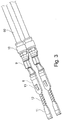
- FIG. 3 shows a connector part 8, which can be produced for example in a stamping process.
- the connector part 8 has a crimping region 9, with which the electrical conductor 60 is mechanically fixed and electrically contacted. With the help of the crimping region 9 and / or separately thereof, a seal 10, in particular a Einzelleiterabdichtung by a corresponding sealing element. Furthermore, the connector part 8 has a contact region 11, a strain relief region 12 and a projection 13.
- two connector parts 8 are shown side by side, because in this embodiment, the cables 5, 6 also each have two electrical conductors 50, 60. But it is also conceivable that only one electrical conductor or more than two electrical conductors are present.
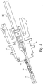
- FIG. 4 After the electrical conductor 60 has been mechanically fastened to the connector part 8 and contacted electrically by means of crimping, the process is carried out according to FIG FIG. 4 around the crimping area 9 around a first encapsulation. This will be done accordingly FIG. 3 prepared connector part inserted into an injection mold and overmoulded with a suitable plastic material. It is important that the material for this extrusion coating 14 is chosen so that on the one hand the ambient conditions (inside the housing 7 high temperatures outside the housing 7 significantly lower temperatures) and the associated temperature fluctuations withstands and at the same time an effective seal realized on the connector part 8 and the outer jacket of the electrical conductors 60 (or the outer jacket of the cable 6).
- the projection 13 of the connector part 8 forms a boundary edge for the injection molding tool, so that the first encapsulation 14 is arranged in the correct position on the connector part 8 and the outgoing electrical conductors 60 by the plastic injection molding process.
- the receiving part for the connector parts 8, which are arranged on the crimping regions 9 at the end of the electrical conductor 60 and seals 10 may also be formed as an independent contact carrier.
- This contact carrier has a corresponding number of connector parts 8 (shown are two connector parts 8, but it can also be more or fewer connector parts 8) through contact chambers for receiving and fixing each connector part 8. If the contact carrier is a finished independent component, it can also be produced in a casting or injection molding process.
- FIG. 5 shows once again the prepared connector part 8 with the already connected electrical conductors 60, wherein the electrical conductors 50 are not yet arranged in the contact region 11.
- FIG. 6 shows that according to FIGS. 4 and 5 Prepared connector part 8 with the first encapsulation 14 (or the independent contact carrier), wherein now in the contact region 11, each electrical conductor 50 of the cable 5 is arranged, that is mechanically fixed and electrically contacted. This is done in a conventional manner z. B. solder, weld, crimp, press or the like.
- FIG. 7 the attachment of a second encapsulation 15.
- the according to FIG. 6 prepared element also inserted into a correspondingly shaped injection mold and filled to form the second encapsulation 15 with plastic material.
- the second encapsulation 15 extends only as far as an end face of the independent contact carrier (as shown) or onto the encapsulation 14 or partially encloses its end region. It is important here, as well as with respect to the first encapsulation 14, that the second encapsulation 15 is made of a material which is adapted to the ambient conditions (outside of the housing 7) and the material properties of the outer jacket of the cable 5 or the electrical conductors 50.
- the second encapsulation 15 is provided in this embodiment with an angled portion 16 in order to realize a rectangular guidance of the electrical conductors 50. It may also be thought to lead the electrical conductors 50 straight (ie without bending) out of the second encapsulation 15 or to set another bend (deviating from 90 degrees).
- the second encapsulation 15 have at least one latching hook 17, by means of which the now completed joint 2 is determined by corresponding locking means on the housing 7 or by the position of the joint 2 in the housing 7 is defined (stop) ,
- the finished joint 2 shown again, which can be ready for use and installed in the passage opening in the housing 7.
- a parting plane is shown, in which the two surrounding areas in the region of the passage opening in the housing 7 are separated from each other.
- the parting plane 18 lies exactly in the region in which the two encapsulations 14, 15 abut each other, but the parting plane 18 can also lie in the axial course of the first encapsulation 14 or in the axial course of the second encapsulation 15.
- the contact carrier 14 can be arranged and fastened in the housing 7, it has at least one latching hook 19, preferably two opposite latching hooks 19 (see FIG FIGS. 4 and 5 ), which cooperate with a stop surface 20 in the housing 7 (see FIG. 2 ).
Landscapes
- Engineering & Computer Science (AREA)
- Mechanical Engineering (AREA)
- Connector Housings Or Holding Contact Members (AREA)
Claims (8)
- Jeu (1) de conducteurs présentant un emplacement de liaison (2) configuré pour convenir à relier l'un à l'autre au moins deux conducteurs électriques (50, 60) et les guider à travers un plan de séparation (18), des conditions ambiantes différentes régnant de part et d'autre du plan de séparation (18), une pièce de liaison (8) étant disposée à une extrémité d'un conducteur électrique (60) et un porte-contact (14) qui loge la ou les pièces de liaison (8) étant prévu, l'autre conducteur électrique (50) étant en contact avec la pièce de liaison (8),
caractérisé en ce que
le porte-contact (14) est inséré hermétiquement dans le plan de séparation (18) grâce à un élément d'étanchéité, le porte-contact (14) étant configuré comme encapsulation et l'élément d'étanchéité constituant un composant fixe du porte-contact (14), le porte-contact (14) étant configuré comme première encapsulation (14) de la pièce de liaison (8) et l'élément d'étanchéité servant de deuxième encapsulation (15) faisant partie intégrante du porte-contact (14). - Jeu (1) de conducteurs présentant un emplacement de liaison (2) selon la revendication 1, caractérisé en ce que le porte-contact (14) est inséré hermétiquement dans le plan de séparation (18).
- Jeu (1) de conducteurs présentant un emplacement de liaison (2) selon les revendications 1 ou 2, caractérisé en ce que le ou les conducteurs électriques (60) sont insérés hermétiquement dans le porte-contact (14) .
- Jeu (1) de conducteurs présentant un emplacement de liaison (2) selon les revendications 1, 2 ou 3, caractérisé en ce que le porte-contact (14) est configuré comme encapsulation.
- Jeu (1) de conducteurs présentant un emplacement de liaison (2) selon les revendications 1, 2, 3 ou 4, caractérisé en ce qu'au moins la partie de contact dans laquelle l'autre conducteur électrique (50) est en contact avec la pièce de liaison (8) est doté de la deuxième encapsulation (15).
- Jeu (1) de conducteurs présentant un emplacement de liaison (2) selon la revendication 5, caractérisé en ce que l'encapsulation (15) présente au moins un crochet d'encliquetage (17), une pince de verrouillage ou similaires.
- Jeu (1) de conducteurs présentant un emplacement de liaison (2) selon l'une des revendications précédentes, caractérisé en ce que le porte-contact (14) présente au moins un crochet d'encliquetage (19) par lequel il accroche le plan de séparation (18) par l'arrière en vue de son immobilisation.
- Jeu (1) de conducteurs présentant un emplacement de liaison (2) selon l'une des revendications précédentes, caractérisé en ce que la pièce de liaison (8) présente une saillie (13) en vue de son immobilisation sur le porte-contact (14).
Applications Claiming Priority (1)
| Application Number | Priority Date | Filing Date | Title |
|---|---|---|---|
| DE102015218006 | 2015-09-18 |
Publications (2)
| Publication Number | Publication Date |
|---|---|
| EP3145040A1 EP3145040A1 (fr) | 2017-03-22 |
| EP3145040B1 true EP3145040B1 (fr) | 2019-03-06 |
Family
ID=57144739
Family Applications (1)
| Application Number | Title | Priority Date | Filing Date |
|---|---|---|---|
| EP16188923.3A Active EP3145040B1 (fr) | 2015-09-18 | 2016-09-15 | Câbles comprenant un point de connexion |
Country Status (3)
| Country | Link |
|---|---|
| EP (1) | EP3145040B1 (fr) |
| DE (1) | DE102016117352A1 (fr) |
| ES (1) | ES2729050T3 (fr) |
Families Citing this family (1)
| Publication number | Priority date | Publication date | Assignee | Title |
|---|---|---|---|---|
| DE102018205611A1 (de) * | 2018-04-13 | 2019-10-17 | Volkswagen Aktiengesellschaft | Gehäuse mit einem Kabeldurchführungselement und Verfahren zur Befestigung eines Sensorkabels an einem Gehäuse einer Kraftfahrzeuglenkung |
Family Cites Families (7)
| Publication number | Priority date | Publication date | Assignee | Title |
|---|---|---|---|---|
| JPS5773256A (en) * | 1980-10-22 | 1982-05-07 | Aisin Warner Ltd | Sealing wire terminal |
| DE9410070U1 (de) * | 1994-06-22 | 1995-10-19 | Bosch Gmbh Robert | Kabeldurchführung für Anschlußkabel eines Sensorelements |
| DE19907636A1 (de) * | 1999-02-23 | 2000-09-21 | Voith Turbo Kg | Vorrichtung zur Kabeldurchführung |
| US6501025B2 (en) * | 1999-11-04 | 2002-12-31 | Clements Manufacturing L.L.C. | Method and apparatus for blocking fluid and fluid vapors |
| DE102005009441A1 (de) * | 2005-03-02 | 2006-09-14 | Hirschmann Automotive Gmbh | Steckverbinder mit einer Crimp-Abdichtung und/oder einer Kabelhalterung |
| WO2011005070A1 (fr) * | 2009-07-10 | 2011-01-13 | Asahi Best Base Sdn. Bhd. | Connecteur photovoltaïque de sécurité surmoulé et étanche à leau |
| EP2763242A1 (fr) * | 2013-02-01 | 2014-08-06 | Delphi Technologies, Inc. | Ensemble connecteur de câble comprenant des éléments d'épissure pour environnements de fluide et procédés de fabrication de celui-ci |
-
2016
- 2016-09-15 EP EP16188923.3A patent/EP3145040B1/fr active Active
- 2016-09-15 ES ES16188923T patent/ES2729050T3/es active Active
- 2016-09-15 DE DE102016117352.5A patent/DE102016117352A1/de not_active Withdrawn
Non-Patent Citations (1)
| Title |
|---|
| None * |
Also Published As
| Publication number | Publication date |
|---|---|
| DE102016117352A1 (de) | 2017-03-23 |
| ES2729050T3 (es) | 2019-10-30 |
| EP3145040A1 (fr) | 2017-03-22 |
Similar Documents
| Publication | Publication Date | Title |
|---|---|---|
| EP1699116B1 (fr) | Prise avec membre d'étanchéité pour les contacts sertis et/ou dispositif de retenue de câble | |
| DE102018201460B4 (de) | Verbinder | |
| EP1750109B1 (fr) | Détecteur de couple et son procédé de fabrication | |
| DE102006012194A1 (de) | Geschirmter Steckverbinder und Verfahren zu seiner Herstellung | |
| EP3485539B1 (fr) | Connecteur enfichable à haute résistance thermique conçu pour un capteur de cliquetis d'un moteur à combustion interne | |
| DE102015121396A1 (de) | Kamera mit einem Gehäuse zum Abschirmen von elektromagnetischer Strahlung und Kraftfahrzeug | |
| EP1703596A1 (fr) | Connecteur avec pièce d'espacement entre au moins deux conducteurs plats pour l'étanchéité lors de moulage par injection et à l'humidité | |
| EP3057183A1 (fr) | Connecteur étanche | |
| EP1699113A2 (fr) | Connecteur électrique | |
| DE102017203820A1 (de) | Steckverbindung | |
| WO2016165705A1 (fr) | Actionneur pour un embrayage de véhicule automobile, comprenant un support dans lequel est maintenue une fiche et module hybride muni d'un tel actionneur | |
| DE102006028880A1 (de) | Kabelverbindung | |
| EP3145040B1 (fr) | Câbles comprenant un point de connexion | |
| EP3340392B1 (fr) | Système de branchement de conduites électriques | |
| DE102015222190A1 (de) | Steckverbinder und Motor- oder Ventilabdeckungselement umfassend einen Steckverbinder | |
| DE202012004919U1 (de) | Dichtungselement für einen elektrischen Steckverbinder und elektrischer Steckverbinder | |
| EP1837955A1 (fr) | Douille à maintien sécurisée pour un connecteur | |
| DE102012207706B4 (de) | Lösbare elektrische Kontaktverbindung | |
| EP2509168B1 (fr) | Connecteur à fiche avec aide à l'introduction de contacts | |
| BE1026233B1 (de) | Steckverbinderteil mit einer Schirmhülse | |
| EP2523260B1 (fr) | Raccordement électrique | |
| DE102011055581A1 (de) | Kontakteinsatz für eine Anhängersteckdose | |
| WO2011032535A1 (fr) | Onduleur | |
| EP3327874A1 (fr) | Ensemble de connecteur électrique comprenant un connecteur, un câble et un tube ondulé entourant ledit câble | |
| DE102021117003A1 (de) | Steckverbindung für Airbag-Zündsysteme |
Legal Events
| Date | Code | Title | Description |
|---|---|---|---|
| PUAI | Public reference made under article 153(3) epc to a published international application that has entered the european phase |
Free format text: ORIGINAL CODE: 0009012 |
|
| STAA | Information on the status of an ep patent application or granted ep patent |
Free format text: STATUS: THE APPLICATION HAS BEEN PUBLISHED |
|
| AK | Designated contracting states |
Kind code of ref document: A1 Designated state(s): AL AT BE BG CH CY CZ DE DK EE ES FI FR GB GR HR HU IE IS IT LI LT LU LV MC MK MT NL NO PL PT RO RS SE SI SK SM TR |
|
| AX | Request for extension of the european patent |
Extension state: BA ME |
|
| STAA | Information on the status of an ep patent application or granted ep patent |
Free format text: STATUS: REQUEST FOR EXAMINATION WAS MADE |
|
| 17P | Request for examination filed |
Effective date: 20170918 |
|
| RBV | Designated contracting states (corrected) |
Designated state(s): AL AT BE BG CH CY CZ DE DK EE ES FI FR GB GR HR HU IE IS IT LI LT LU LV MC MK MT NL NO PL PT RO RS SE SI SK SM TR |
|
| STAA | Information on the status of an ep patent application or granted ep patent |
Free format text: STATUS: EXAMINATION IS IN PROGRESS |
|
| 17Q | First examination report despatched |
Effective date: 20180319 |
|
| GRAP | Despatch of communication of intention to grant a patent |
Free format text: ORIGINAL CODE: EPIDOSNIGR1 |
|
| STAA | Information on the status of an ep patent application or granted ep patent |
Free format text: STATUS: GRANT OF PATENT IS INTENDED |
|
| INTG | Intention to grant announced |
Effective date: 20181031 |
|
| GRAS | Grant fee paid |
Free format text: ORIGINAL CODE: EPIDOSNIGR3 |
|
| GRAA | (expected) grant |
Free format text: ORIGINAL CODE: 0009210 |
|
| STAA | Information on the status of an ep patent application or granted ep patent |
Free format text: STATUS: THE PATENT HAS BEEN GRANTED |
|
| AK | Designated contracting states |
Kind code of ref document: B1 Designated state(s): AL AT BE BG CH CY CZ DE DK EE ES FI FR GB GR HR HU IE IS IT LI LT LU LV MC MK MT NL NO PL PT RO RS SE SI SK SM TR |
|
| REG | Reference to a national code |
Ref country code: GB Ref legal event code: FG4D Free format text: NOT ENGLISH |
|
| REG | Reference to a national code |
Ref country code: CH Ref legal event code: EP Ref country code: AT Ref legal event code: REF Ref document number: 1105832 Country of ref document: AT Kind code of ref document: T Effective date: 20190315 |
|
| REG | Reference to a national code |
Ref country code: DE Ref legal event code: R096 Ref document number: 502016003605 Country of ref document: DE |
|
| REG | Reference to a national code |
Ref country code: IE Ref legal event code: FG4D Free format text: LANGUAGE OF EP DOCUMENT: GERMAN |
|
| REG | Reference to a national code |
Ref country code: RO Ref legal event code: EPE |
|
| REG | Reference to a national code |
Ref country code: NL Ref legal event code: MP Effective date: 20190306 |
|
| REG | Reference to a national code |
Ref country code: LT Ref legal event code: MG4D |
|
| PG25 | Lapsed in a contracting state [announced via postgrant information from national office to epo] |
Ref country code: FI Free format text: LAPSE BECAUSE OF FAILURE TO SUBMIT A TRANSLATION OF THE DESCRIPTION OR TO PAY THE FEE WITHIN THE PRESCRIBED TIME-LIMIT Effective date: 20190306 Ref country code: NO Free format text: LAPSE BECAUSE OF FAILURE TO SUBMIT A TRANSLATION OF THE DESCRIPTION OR TO PAY THE FEE WITHIN THE PRESCRIBED TIME-LIMIT Effective date: 20190606 Ref country code: SE Free format text: LAPSE BECAUSE OF FAILURE TO SUBMIT A TRANSLATION OF THE DESCRIPTION OR TO PAY THE FEE WITHIN THE PRESCRIBED TIME-LIMIT Effective date: 20190306 Ref country code: LT Free format text: LAPSE BECAUSE OF FAILURE TO SUBMIT A TRANSLATION OF THE DESCRIPTION OR TO PAY THE FEE WITHIN THE PRESCRIBED TIME-LIMIT Effective date: 20190306 |
|
| PG25 | Lapsed in a contracting state [announced via postgrant information from national office to epo] |
Ref country code: HR Free format text: LAPSE BECAUSE OF FAILURE TO SUBMIT A TRANSLATION OF THE DESCRIPTION OR TO PAY THE FEE WITHIN THE PRESCRIBED TIME-LIMIT Effective date: 20190306 Ref country code: RS Free format text: LAPSE BECAUSE OF FAILURE TO SUBMIT A TRANSLATION OF THE DESCRIPTION OR TO PAY THE FEE WITHIN THE PRESCRIBED TIME-LIMIT Effective date: 20190306 Ref country code: NL Free format text: LAPSE BECAUSE OF FAILURE TO SUBMIT A TRANSLATION OF THE DESCRIPTION OR TO PAY THE FEE WITHIN THE PRESCRIBED TIME-LIMIT Effective date: 20190306 Ref country code: GR Free format text: LAPSE BECAUSE OF FAILURE TO SUBMIT A TRANSLATION OF THE DESCRIPTION OR TO PAY THE FEE WITHIN THE PRESCRIBED TIME-LIMIT Effective date: 20190607 Ref country code: BG Free format text: LAPSE BECAUSE OF FAILURE TO SUBMIT A TRANSLATION OF THE DESCRIPTION OR TO PAY THE FEE WITHIN THE PRESCRIBED TIME-LIMIT Effective date: 20190606 Ref country code: LV Free format text: LAPSE BECAUSE OF FAILURE TO SUBMIT A TRANSLATION OF THE DESCRIPTION OR TO PAY THE FEE WITHIN THE PRESCRIBED TIME-LIMIT Effective date: 20190306 |
|
| REG | Reference to a national code |
Ref country code: ES Ref legal event code: FG2A Ref document number: 2729050 Country of ref document: ES Kind code of ref document: T3 Effective date: 20191030 |
|
| PG25 | Lapsed in a contracting state [announced via postgrant information from national office to epo] |
Ref country code: EE Free format text: LAPSE BECAUSE OF FAILURE TO SUBMIT A TRANSLATION OF THE DESCRIPTION OR TO PAY THE FEE WITHIN THE PRESCRIBED TIME-LIMIT Effective date: 20190306 Ref country code: PT Free format text: LAPSE BECAUSE OF FAILURE TO SUBMIT A TRANSLATION OF THE DESCRIPTION OR TO PAY THE FEE WITHIN THE PRESCRIBED TIME-LIMIT Effective date: 20190706 Ref country code: AL Free format text: LAPSE BECAUSE OF FAILURE TO SUBMIT A TRANSLATION OF THE DESCRIPTION OR TO PAY THE FEE WITHIN THE PRESCRIBED TIME-LIMIT Effective date: 20190306 Ref country code: SK Free format text: LAPSE BECAUSE OF FAILURE TO SUBMIT A TRANSLATION OF THE DESCRIPTION OR TO PAY THE FEE WITHIN THE PRESCRIBED TIME-LIMIT Effective date: 20190306 |
|
| PG25 | Lapsed in a contracting state [announced via postgrant information from national office to epo] |
Ref country code: SM Free format text: LAPSE BECAUSE OF FAILURE TO SUBMIT A TRANSLATION OF THE DESCRIPTION OR TO PAY THE FEE WITHIN THE PRESCRIBED TIME-LIMIT Effective date: 20190306 Ref country code: PL Free format text: LAPSE BECAUSE OF FAILURE TO SUBMIT A TRANSLATION OF THE DESCRIPTION OR TO PAY THE FEE WITHIN THE PRESCRIBED TIME-LIMIT Effective date: 20190306 |
|
| REG | Reference to a national code |
Ref country code: DE Ref legal event code: R097 Ref document number: 502016003605 Country of ref document: DE |
|
| PG25 | Lapsed in a contracting state [announced via postgrant information from national office to epo] |
Ref country code: IS Free format text: LAPSE BECAUSE OF FAILURE TO SUBMIT A TRANSLATION OF THE DESCRIPTION OR TO PAY THE FEE WITHIN THE PRESCRIBED TIME-LIMIT Effective date: 20190706 |
|
| PLBE | No opposition filed within time limit |
Free format text: ORIGINAL CODE: 0009261 |
|
| STAA | Information on the status of an ep patent application or granted ep patent |
Free format text: STATUS: NO OPPOSITION FILED WITHIN TIME LIMIT |
|
| PG25 | Lapsed in a contracting state [announced via postgrant information from national office to epo] |
Ref country code: DK Free format text: LAPSE BECAUSE OF FAILURE TO SUBMIT A TRANSLATION OF THE DESCRIPTION OR TO PAY THE FEE WITHIN THE PRESCRIBED TIME-LIMIT Effective date: 20190306 |
|
| 26N | No opposition filed |
Effective date: 20191209 |
|
| PG25 | Lapsed in a contracting state [announced via postgrant information from national office to epo] |
Ref country code: SI Free format text: LAPSE BECAUSE OF FAILURE TO SUBMIT A TRANSLATION OF THE DESCRIPTION OR TO PAY THE FEE WITHIN THE PRESCRIBED TIME-LIMIT Effective date: 20190306 |
|
| PG25 | Lapsed in a contracting state [announced via postgrant information from national office to epo] |
Ref country code: TR Free format text: LAPSE BECAUSE OF FAILURE TO SUBMIT A TRANSLATION OF THE DESCRIPTION OR TO PAY THE FEE WITHIN THE PRESCRIBED TIME-LIMIT Effective date: 20190306 |
|
| PG25 | Lapsed in a contracting state [announced via postgrant information from national office to epo] |
Ref country code: MC Free format text: LAPSE BECAUSE OF FAILURE TO SUBMIT A TRANSLATION OF THE DESCRIPTION OR TO PAY THE FEE WITHIN THE PRESCRIBED TIME-LIMIT Effective date: 20190306 |
|
| REG | Reference to a national code |
Ref country code: CH Ref legal event code: PL |
|
| PG25 | Lapsed in a contracting state [announced via postgrant information from national office to epo] |
Ref country code: LI Free format text: LAPSE BECAUSE OF NON-PAYMENT OF DUE FEES Effective date: 20190930 Ref country code: IE Free format text: LAPSE BECAUSE OF NON-PAYMENT OF DUE FEES Effective date: 20190915 Ref country code: CH Free format text: LAPSE BECAUSE OF NON-PAYMENT OF DUE FEES Effective date: 20190930 Ref country code: LU Free format text: LAPSE BECAUSE OF NON-PAYMENT OF DUE FEES Effective date: 20190915 |
|
| REG | Reference to a national code |
Ref country code: BE Ref legal event code: MM Effective date: 20190930 |
|
| PG25 | Lapsed in a contracting state [announced via postgrant information from national office to epo] |
Ref country code: BE Free format text: LAPSE BECAUSE OF NON-PAYMENT OF DUE FEES Effective date: 20190930 |
|
| PG25 | Lapsed in a contracting state [announced via postgrant information from national office to epo] |
Ref country code: CY Free format text: LAPSE BECAUSE OF FAILURE TO SUBMIT A TRANSLATION OF THE DESCRIPTION OR TO PAY THE FEE WITHIN THE PRESCRIBED TIME-LIMIT Effective date: 20190306 |
|
| PG25 | Lapsed in a contracting state [announced via postgrant information from national office to epo] |
Ref country code: HU Free format text: LAPSE BECAUSE OF FAILURE TO SUBMIT A TRANSLATION OF THE DESCRIPTION OR TO PAY THE FEE WITHIN THE PRESCRIBED TIME-LIMIT; INVALID AB INITIO Effective date: 20160915 Ref country code: MT Free format text: LAPSE BECAUSE OF FAILURE TO SUBMIT A TRANSLATION OF THE DESCRIPTION OR TO PAY THE FEE WITHIN THE PRESCRIBED TIME-LIMIT Effective date: 20190306 |
|
| PG25 | Lapsed in a contracting state [announced via postgrant information from national office to epo] |
Ref country code: MK Free format text: LAPSE BECAUSE OF FAILURE TO SUBMIT A TRANSLATION OF THE DESCRIPTION OR TO PAY THE FEE WITHIN THE PRESCRIBED TIME-LIMIT Effective date: 20190306 |
|
| REG | Reference to a national code |
Ref country code: AT Ref legal event code: MM01 Ref document number: 1105832 Country of ref document: AT Kind code of ref document: T Effective date: 20210915 |
|
| PG25 | Lapsed in a contracting state [announced via postgrant information from national office to epo] |
Ref country code: AT Free format text: LAPSE BECAUSE OF NON-PAYMENT OF DUE FEES Effective date: 20210915 |
|
| PGFP | Annual fee paid to national office [announced via postgrant information from national office to epo] |
Ref country code: RO Payment date: 20230913 Year of fee payment: 8 Ref country code: GB Payment date: 20230920 Year of fee payment: 8 Ref country code: CZ Payment date: 20230912 Year of fee payment: 8 |
|
| PGFP | Annual fee paid to national office [announced via postgrant information from national office to epo] |
Ref country code: FR Payment date: 20230928 Year of fee payment: 8 Ref country code: DE Payment date: 20230920 Year of fee payment: 8 |
|
| PGFP | Annual fee paid to national office [announced via postgrant information from national office to epo] |
Ref country code: ES Payment date: 20231124 Year of fee payment: 8 |
|
| PGFP | Annual fee paid to national office [announced via postgrant information from national office to epo] |
Ref country code: IT Payment date: 20230927 Year of fee payment: 8 |