EP3144894B1 - Verfahren und system zur kalibrierung einer bilderfassungsvorrichtung und entsprechendes computerprogrammprodukt - Google Patents
Verfahren und system zur kalibrierung einer bilderfassungsvorrichtung und entsprechendes computerprogrammprodukt Download PDFInfo
- Publication number
- EP3144894B1 EP3144894B1 EP16189477.9A EP16189477A EP3144894B1 EP 3144894 B1 EP3144894 B1 EP 3144894B1 EP 16189477 A EP16189477 A EP 16189477A EP 3144894 B1 EP3144894 B1 EP 3144894B1
- Authority
- EP
- European Patent Office
- Prior art keywords
- pattern
- image
- light source
- source
- pixel
- Prior art date
- Legal status (The legal status is an assumption and is not a legal conclusion. Google has not performed a legal analysis and makes no representation as to the accuracy of the status listed.)
- Active
Links
- 238000000034 method Methods 0.000 title claims description 43
- 238000004590 computer program Methods 0.000 title description 4
- 210000001747 pupil Anatomy 0.000 claims description 19
- 230000001747 exhibiting effect Effects 0.000 claims description 5
- 230000003287 optical effect Effects 0.000 description 47
- 230000006870 function Effects 0.000 description 15
- 238000003860 storage Methods 0.000 description 14
- 238000013461 design Methods 0.000 description 11
- 238000003491 array Methods 0.000 description 6
- 238000010586 diagram Methods 0.000 description 6
- 238000012545 processing Methods 0.000 description 5
- 238000010420 art technique Methods 0.000 description 4
- 238000012937 correction Methods 0.000 description 4
- 238000003384 imaging method Methods 0.000 description 4
- 238000004458 analytical method Methods 0.000 description 3
- 238000012804 iterative process Methods 0.000 description 3
- 238000013519 translation Methods 0.000 description 3
- 238000013459 approach Methods 0.000 description 2
- 238000004891 communication Methods 0.000 description 2
- 238000009826 distribution Methods 0.000 description 2
- 238000012986 modification Methods 0.000 description 2
- 230000004048 modification Effects 0.000 description 2
- 238000012805 post-processing Methods 0.000 description 2
- 239000004065 semiconductor Substances 0.000 description 2
- 230000001131 transforming effect Effects 0.000 description 2
- 238000012512 characterization method Methods 0.000 description 1
- 239000000470 constituent Substances 0.000 description 1
- 230000007547 defect Effects 0.000 description 1
- 239000011521 glass Substances 0.000 description 1
- 238000005286 illumination Methods 0.000 description 1
- 230000004807 localization Effects 0.000 description 1
- 238000004519 manufacturing process Methods 0.000 description 1
- 239000011159 matrix material Substances 0.000 description 1
- 238000003909 pattern recognition Methods 0.000 description 1
- 238000009877 rendering Methods 0.000 description 1
- 239000000758 substrate Substances 0.000 description 1
- 230000009897 systematic effect Effects 0.000 description 1
Images


Classifications
-
- G—PHYSICS
- G06—COMPUTING; CALCULATING OR COUNTING
- G06T—IMAGE DATA PROCESSING OR GENERATION, IN GENERAL
- G06T7/00—Image analysis
- G06T7/60—Analysis of geometric attributes
-
- G—PHYSICS
- G06—COMPUTING; CALCULATING OR COUNTING
- G06T—IMAGE DATA PROCESSING OR GENERATION, IN GENERAL
- G06T7/00—Image analysis
- G06T7/80—Analysis of captured images to determine intrinsic or extrinsic camera parameters, i.e. camera calibration
-
- G—PHYSICS
- G06—COMPUTING; CALCULATING OR COUNTING
- G06T—IMAGE DATA PROCESSING OR GENERATION, IN GENERAL
- G06T5/00—Image enhancement or restoration
- G06T5/20—Image enhancement or restoration using local operators
-
- G—PHYSICS
- G06—COMPUTING; CALCULATING OR COUNTING
- G06T—IMAGE DATA PROCESSING OR GENERATION, IN GENERAL
- G06T5/00—Image enhancement or restoration
- G06T5/73—Deblurring; Sharpening
-
- H—ELECTRICITY
- H04—ELECTRIC COMMUNICATION TECHNIQUE
- H04N—PICTORIAL COMMUNICATION, e.g. TELEVISION
- H04N17/00—Diagnosis, testing or measuring for television systems or their details
- H04N17/002—Diagnosis, testing or measuring for television systems or their details for television cameras
-
- G—PHYSICS
- G06—COMPUTING; CALCULATING OR COUNTING
- G06T—IMAGE DATA PROCESSING OR GENERATION, IN GENERAL
- G06T2200/00—Indexing scheme for image data processing or generation, in general
- G06T2200/21—Indexing scheme for image data processing or generation, in general involving computational photography
-
- G—PHYSICS
- G06—COMPUTING; CALCULATING OR COUNTING
- G06T—IMAGE DATA PROCESSING OR GENERATION, IN GENERAL
- G06T2207/00—Indexing scheme for image analysis or image enhancement
- G06T2207/10—Image acquisition modality
- G06T2207/10052—Images from lightfield camera
-
- G—PHYSICS
- G06—COMPUTING; CALCULATING OR COUNTING
- G06T—IMAGE DATA PROCESSING OR GENERATION, IN GENERAL
- G06T2207/00—Indexing scheme for image analysis or image enhancement
- G06T2207/20—Special algorithmic details
- G06T2207/20036—Morphological image processing
-
- G—PHYSICS
- G06—COMPUTING; CALCULATING OR COUNTING
- G06T—IMAGE DATA PROCESSING OR GENERATION, IN GENERAL
- G06T2207/00—Indexing scheme for image analysis or image enhancement
- G06T2207/20—Special algorithmic details
- G06T2207/20048—Transform domain processing
Definitions
- the present disclosure relates to image or video camera calibration. More precisely, the present disclosure generally relates to a method and a system for calibrating an image acquisition device, notably, but not exclusively, a plenoptic or multi-lens camera or a camera array.
- Image acquisition devices project a three-dimensional scene onto a two-dimensional sensor.
- a conventional capture device captures a two-dimensional (2-D) image of the scene representing an amount of light that reaches a photosensor (or photodetector or photosite) within the device.
- this 2-D image contains no information about the directional distribution of the light rays that reach the photosensor (which may be referred to as the light-field).
- the terms "object space” and “image space” respectively stand for the input and output optical spaces usually defined in the optical design discipline.
- the "object space” is the observed scene in front of the main lens of an image acquisition device, while the “image space” is the optical space after the optical system of the image acquisition device (main lens, microlenses, ...) where the imaging photosensor captures an image.
- optical systems calibration mainly use checkerboards or grids of points in the object space to estimate the position of corners or intersection points on the acquired images in the image space.
- grid points or corners positions are estimated with sub-pixel image processing techniques, and these estimates are provided to a model generalizing the estimated positions to the entire field of view.
- Such a perspective projection model is usually taken as a starting point for optical acquisition devices calibration. It is then supplemented with distortion terms, in order to get very precise calibration of all pixels in the camera.
- light-field capture devices also referred to as “light-field data acquisition devices” have been designed to measure a four-dimensional (4D) light-field of the scene by capturing the light directions from different viewpoints of that scene.
- these devices can capture additional optical information (information about the directional distribution of the bundle of light rays) for providing new imaging applications by post-processing.
- the information acquired/obtained by a light-field capture device is referred to as the light-field data.
- Light-field capture devices are defined herein as any devices that are capable of capturing light-field data. There are several types of light-field capture devices, among which:
- JP 2012 205014 A discloses the calibration of a light field camera using a light pattern of parallel incident rays to measure lenslet positioning errors during manufacture. Misalignments of the optical axes of the main lens and the micro lens array are derived and centroids and chief rays are analysed.
- EP 2736262 A2 concerns plenoptic camera calibration based on centroids of superpixels, e.g. using an illumination pattern. Superpixel centroids can be iteratively adjusted.
- Such a technique does not allow determining with enough precision the chief ray position and direction estimation in the object space, nor the geometrical characteristics of the object space region seen by a given pixel.
- Such an object space region may also be called a pixel beam in the present disclosure.
- a method of calibrating an image acquisition device is provided according to claim 1.
- image acquisition device is used for designating all these devices, whatever their characteristics and features.
- a multiple source point emitting device for example several light sources arranged in a grid or lattice
- emissive power and emitting diagram or beam pattern
- a monitor or projection display can be used.
- a projector with corrected uniformity and using a diffusing screen is used to emit light source patterns.
- the light source patterns are emitted toward an image acquisition device, such as a camera (with potentially multiple light paths), for which correspondence is sought between pixels on one or several sensor plane(s) and beams in the observed object space.
- the camera includes optical elements projecting the observed object space into the sensor plane(s) (e.g. including a main lens and optionally microlenses, or including multiple camera lenses like in a camera array configuration).
- a light path is identified from the observed object space to the image plane, and is defined by an entrance pupil (e.g. one of multiple microlenses pupils retro-images or one of multiple cameras entrance pupils in a camera array.
- an entrance pupil e.g. one of multiple microlenses pupils retro-images or one of multiple cameras entrance pupils in a camera array.
- some pixels may have different light paths to the scene, e.g. through two or more microlenses).
- the method of the present disclosure allows to precisely characterize the pixel beam, which reaches a given pixel on the sensor.
- centroid of a shape it is meant here, and throughout this document, the arithmetic mean position of all the points in the shape.
- the method also comprises determining a homomorphic transform between a source plane and an image plane of the image acquisition device, and said adjusting comprises iteratively modifying said source pattern to obtain said target image pattern, an inverse homomorphic transform of a difference between said image pattern and said target image pattern being determined at each iteration of said iteratively modifying step.
- the method of the present disclosure thus relies on an initial phase, allowing determining a local source space to image space homomorphism, which may be done by classical calibration techniques.
- this homomorphism may be determined by emitting a non-symmetric light source pattern including several anchor points, and by estimating an homomorphic transform approximation between the source plane and the image plane linking the source and image patterns. This homomorphic transform can be approximated by knowing the optical system model for the given light path in the vicinity of the reference pixel and of the source point corresponding to this reference pixel.
- This homomorphic transform is used in an iterative process of adjusting the light source pattern until the image pattern formed on the sensor shows the shape of a target image pattern. Such an iterative process allows achieving a great precision.
- said target image pattern is an image pattern exhibiting central symmetry centered on the reference pixel.
- the centroid of the reference pixel corresponds to the center of symmetry of the target image pattern.
- analyzing the adjusted source pattern comprises determining a centroid of the adjusted source pattern, and the estimating comprises determining a chief ray of the pixel beam, said chief ray being defined by the centroid of the adjusted source pattern and by a center of an entrance pupil through which the pixel beam reaches the reference pixel.
- the source spot centroid or maximum provides the intersection of the chief ray with the source plane. This intersection, combined with the light path entrance pupil center, provides the chief ray associated with the reference pixel.
- said estimating also comprises:
- the pixel beam is characterized.
- Knowledge of the optical design of the used optical system provides the light path entrance pupil characteristics and the information whether the pixel beam is converging or diverging when crossing the source plane. All pixel beam geometric characteristics are thus obtained.
- such a method comprises alternately emitting a first light source pattern at a first distance to the image acquisition device in the object space and a second light source pattern at a second distance to the image acquisition device distinct from the first distance in the object space, said step of determining an image pattern and said step of adjusting the source pattern are carried out for the first light source pattern and for the second light source pattern with a first target image pattern for the first light source pattern and a second target image pattern for the second light source pattern both centered on a same reference pixel, and said analyzing step comprises analyzing the adjusted first source pattern and the adjusted second source pattern in order to estimate the at least one characteristic of the pixel beam directed to the reference pixel.
- the method disclosed previously in this document is implemented with at least two source point emitting devices virtually placed at different distances from the image acquisition device to be characterized.
- the local source spot adjustment phase is achieved in two distinct source planes. It is hence not necessary anymore to have precise optical design knowledge in order to evaluate pixel beams geometry.
- such a method also comprises:
- the source versus image magnification has the same sign for both light source patterns, it implies that the beam between both source planes has a truncated cone shape.
- both magnifications have opposite signs, the reference pixel conjugate point is located between both source planes, and the beam between the first source plane and the second source plane has a double cone shape.
- the present disclosure also concerns a computer program product downloadable from a communication network and/or recorded on a medium readable by a computer and/or executable by a processor, comprising program code instructions for implementing a method as described previously.
- the present disclosure also concerns a non-transitory computer-readable medium comprising a computer program product recorded thereon and capable of being run by a processor, including program code instructions for implementing a method as described previously.
- Such computer programs may be stored on a computer readable storage medium.
- a computer readable storage medium as used herein is considered a non-transitory storage medium given the inherent capability to store the information therein as well as the inherent capability to provide retrieval of the information therefrom.
- a computer readable storage medium can be, for example, but is not limited to, an electronic, magnetic, optical, electromagnetic, infrared, or semiconductor system, apparatus, or device, or any suitable combination of the foregoing.
- the present disclosure also concerns a system for calibrating an image acquisition device according to claim 7.
- the first light source may be a multiple source point emitting device (for example several light sources arranged in a grid or lattice).
- a monitor or projection display can also be used, as well as a projector with corrected uniformity and using a diffusing screen.
- such a system also comprises a computing unit for determining a homomorphic transform between a source plane and an image plane of the image acquisition device, and said module for adjusting comprises a feedback loop for iteratively modifying the first light source pattern to obtain the target first image pattern, an inverse homomorphic transform of a difference between the first image pattern and the target first image pattern being determined at each iteration of said feedback loop.
- said analyzing unit is able to determine:
- said analyzing unit also comprises:
- such a system also comprises a second light source able to emit a second light source pattern in an object space of the image acquisition device, the first light source being located at a first distance to the image acquisition device and the second light source being located at a second distance to the image acquisition device distinct from the first distance.
- such a system also comprises a beam splitter separating the first and second light sources.
- Such a beam splitter allows virtually placing the first and second light sources at different distances from the image acquisition device.
- a beam splitter separates two projection screens or monitors covering a same field of view and with emitting elements of similar angular resolution when observed from the acquisition device.
- the second light source is located between the first light source and the image acquisition device, and the second light source is a screen able to take:
- both light sources may be placed in the same direction with respect to the image acquisition device, at different distances, without the need to use a beam splitter.
- such a system also comprises:
- references in the specification to "one embodiment” or “an embodiment”, indicate that the embodiment described may include a particular feature, structure, or characteristic, but every embodiment may not necessarily include the particular feature, structure, or characteristic. Moreover, such phrases are not necessarily referring to the same embodiment. Further, when a particular feature, structure, or characteristic is described in connection with an embodiment, it is submitted that it is within the knowledge of one skilled in the art to affect such feature, structure, or characteristic in connection with other embodiments whether or not explicitly described.
- the exemplary embodiments are described in relation to a light-field acquisition device, such as a plenoptic camera.
- a light-field acquisition device such as a plenoptic camera.
- the scope of the invention must not be limited to such plenoptic devices, and applies for any kind of image acquisition device, whether a conventional device or a light-field acquisition device.
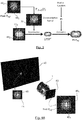
- Figure 1 depicts elements of a system for calibrating a plenoptic camera according to an embodiment of the present disclosure.
- Such a plenoptic camera is an optical system 1 comprising a main lens 10 (or a set of lenses, which may be represented synthetically as a single main lens), and a microlens array 11, located between the main lens 10 and a sensor 12.
- the right hand side of figure 1 with respect to main lens 10 and microlens array 11 corresponds to the image space of the plenoptic camera, where the imaging photosensor 12 captures an image.
- the left hand side of figure 1 with respect to main lens 10 corresponds to the object space, i.e. the observed scene in front of the main lens.
- One or several light sources emit light from the object space towards optical system 1.
- a multiple source point emitting device of known relative position, emissive power and emitting diagram (beam pattern) may be used, which may consist for example in several light sources arranged in a grid or lattice.
- a monitor or projection display may also be used.
- a projector with corrected uniformity and using a diffusing screen is used.
- Part of the emitted light is received on a reference pixel P ref on sensor 12.
- such a pixel beam comprises a part 21 located in the object space and a part 22 located in the image space.
- the chief ray of this pixel beam is denoted as 2.
- scene points may have different light paths to the sensor (e.g. through two or more microlenses 11).
- a given light path from the observed object space to the image plane is identified.
- Such a light path is defined by an entrance pupil, i.e.:
- the light source and sensor 12 are supposed linear or calibrated to linear in their electronic signal to light amplitude transform (for the source) and light amplitude to electronic signal transform (for the sensor 12).
- an initial phase is carried out, aiming at determining a local source space to image space homomorphism.
- such an initial phase is done by classical calibration technique to obtain extrinsic parameters, such as described for example by Zhang, Zhengyou in "A flexible new technique for camera calibration.” Pattern Analysis and Machine Intelligence, IEEE Transactions on 22, no. 11 (2000): 1330-1334 .
- Figures 2A and 2B show the image spot formed on sensor 12 of the plenoptic camera of figure 1 , respectively before and after such a source spot adjustment.
- the image spot of figure 2A before source spot adjustment, shows an ovoid shape, schematically illustrated in dashed lines, which surrounds two main pixels. The upper one is chosen as a reference pixel P ref .
- the source spot will be iteratively adjusted, such that the image spot of figure 2A is transformed into the image spot of figure 2B , which centroid corresponds to, or is superposed with, the centroid of the reference pixel P ref .
- the image spot now shows a circular shape, also shown in dashed lines, which encloses five main pixels, and which center of symmetry corresponds to reference pixel P ref .
- the iterative adjustment of the source pattern in order to obtain a pixel centered and symmetric image pattern, may be carried out according to the following steps:
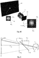
- Figures 4A and 4B schematically depict the optical system for calibrating the plenoptic camera of figure 1 , and notably the source and image spots before and after iterative adjustment.
- the light source is a screen 40 on which is displayed a source spot consisting in a 5x5 array 44 1 of source points of different intensities.
- the source spot 41 1 shows an overall circular shape, shown in dashed lines.
- Light from source spot 41 1 travels through an optical system 1 (the plenoptic camera of figure 1 , or more generally any kind of optical system of any type) and forms an image spot 42 1 on the focal plane 43 of the optical system 1.
- image spot comprises a 5x6 array 46 1 of source point of different intensities and shows the ovoid shape 42 1 already described in relation to figure 2A .
- the image spot comprises a 5x7 array 46 2 of source points and now shows an overall circular shape 42 2 , shown in dashed lines, and which center of symmetry corresponds to the centroid of reference pixel P ref .
- Such an image spot 42 2 corresponds to the image spot already described in relation to figure 2B .
- the shape of the source pattern has also been modified: after iterative adjustment, the source spot 41 2 shows an elongated ovoid shape. Its size has also been modified and the source spot now consists in a 5x6 array 44 2 of source points of different intensities. Its centroid or maximum 45 provides the intersection of the chief ray 2 with the source plane. This intersection combined with the light path entrance pupil 4 center provides the chief ray 2 associated with pixel P ref .
- step S5 consists in analyzing the resultant source spot pattern, after iterative adjustment, to determine its centroid, in order to characterize its chief ray.
- Step S6 comprises analyzing the resultant source spot and image spot patterns to determine their extensions in the object and image spaces respectively. It is schematically illustrated in figure 3 .
- the source spot S after iterative adjustment 41 2 , 44 2 is deconvolved by this resultant spot 30.
- This myopic (as T I ⁇ S ( I ) is potentially inaccurate) deconvolution provides the local point spread function ( LPSF' ) if light was travelling from image to source. It is actually recalled that myopic deconvolution occurs when the PSF (deconvolution kernel) is partially known. There is then the need to solve both the deconvolved object and the PSF (see for example http://cfao.ucolick.org/meetings/psf_reconstruction/pdf/christou.pdf).
- This local point spread function LPSF' is then convolved with a transform of a box filter ⁇ representing the fill function of the pixel, to give the pixel beam profile ( PBP ref ) for P ref at source distance.
- PB P ref LPSF ' ⁇ T I ⁇ S ⁇
- the pixel beam is characterized.
- Knowledge of the optical design provides the light path entrance pupil characteristics and the information whether the pixel beam is converging or diverging when crossing the source plane. In this way, all P ref pixel beam geometric characteristics are obtained.
- Figures 5 and 6 describe an alternate embodiment, according to which it is not necessary to have knowledge of the optical system design (knowledge of the entrance pupil of a determined light path) to fully characterize the pixel beam.
- a plenoptic system may be described with a hundred entrance pupils defining a hundred light paths, e.g. in a 10x10 grid.
- Figure 5 depicts an alternate embodiment to figure 1 , in which at least two source point emitting devices are virtually placed at different distances from the camera device 1 to be characterized and calibrated.
- the light sources of figure 5 are multiple source point emitting devices (for example several light sources arranged in a grid or lattice) of known relative position, emissive power and emitting diagram (beam pattern).
- a monitor or projection display can be used.
- a projector with corrected uniformity and using a diffusing screen is an advantageous solution.
- the source point emitting devices are placed at two distinct distances of the camera to calibrate, for example covering a same field of view and with emitting elements of the similar angular resolution when observed from the acquisition device.
- a first light source is located at source plane 51, while a second light source is located at source plane 52 1 .
- the light sources are two projection screens or monitors, with the second light source 52 1 being redirected by means of a beam splitter 53.
- plane 52 1 corresponds to the actual source plane of the second light source
- plane 52 2 corresponds to its virtual position, as induced by the use of the beam splitter 53.
- optical system 1 designates a camera (with potentially multiple light paths) for which correspondence is sought between pixels on one or several sensor plane(s) and beams in the observed object space.
- Numerical reference 54 1 designates a source spot on the first source plane 51
- numerical reference 54 2 designates a source spot on the second source plane 52 1 , 52 2
- Source spots 54 1 and 54 2 located at different distances from optical system 1, are displayed sequentially, and they are both iteratively adjusted, as described previously in relation to figures 1 to 4B .
- Such a specific screen is then placed in the virtual second source plane 52 2 on figure 5 .
- the screen in the second source plane 52 2 is in its transparent state.
- the screen in the second source plane 52 2 starts emitting a second source spot 54 2 towards optical system 1.
- the screen is first located at the first distance to the image acquisition device. Steps S51 to S54 are carried out for the screen in this first position. The screen is then displaced from the first position to a second position, at a second distance to the image acquisition device. Steps S55 to S59 are then carried out for the screen located at the second distance to the image acquisition device. Step S60 is then executed.
- Figure 7 shows a schematic block diagram illustrating an example of parts of a system for calibrating an image acquisition device according to an embodiment of the present disclosure.
- An apparatus 70 illustrated in Figure 7 includes a processor 71, a storage unit 72, an input device 73, an output device 74, and an interface unit 75 which are connected by a bus 76.
- constituent elements of the computer apparatus 70 may be connected by a connection other than a bus connection using the bus 76.
- the processor 71 controls operations of the apparatus 70.
- the storage unit 72 stores at least one program to be executed by the processor 71, and various data, including data relating to the adjusted source spots, parameters used by computations performed by the processor 71, intermediate data of computations performed by the processor 71, and so on.
- the processor 71 may be formed by any known and suitable hardware, or software, or a combination of hardware and software.
- the processor 71 may be formed by dedicated hardware such as a processing circuit, or by a programmable processing unit such as a CPU (Central Processing Unit) that executes a program stored in a memory thereof.
- CPU Central Processing Unit
- the storage unit 72 may be formed by any suitable storage or means capable of storing the program, data, or the like in a computer-readable manner. Examples of the storage unit 72 include non-transitory computer-readable storage media such as semiconductor memory devices, and magnetic, optical, or magneto-optical recording media loaded into a read and write unit.
- the program causes the processor 71 to perform a process for calibrating an image acquisition device according to an embodiment of the present disclosure as described previously.
- the input device 73 may be formed by a keyboard, a pointing device such as a mouse, or the like for use by the user to input commands.
- the output device 74 may be formed by a display device to display, for example, the calibration data of the image acquisition device, including the geometric characteristics of the pixel beams.
- the input device 73 and the output device 74 may be formed integrally by a touchscreen panel, for example.
- the interface unit 75 provides an interface between the apparatus 70 and an external apparatus.
- the interface unit 75 may be communicable with the external apparatus via cable or wireless communication.
- the external apparatus may be the image acquisition device 1 and the light sources 40, 51, 52.
- the adjusted source spots displayed by the light sources 40, 51, 52 can be input from the light sources to the apparatus 70 through the interface unit 75, then stored in the storage unit 72.
- processor 71 may comprise different modules and units embodying the functions carried out by apparatus 70 according to embodiments of the present disclosure, such as:
- such a processor 71 also comprises a computing unit for determining a homomorphic transform between a source plane and an image plane of the image acquisition device, and the module for adjusting comprises a feedback loop for iteratively modifying the light source pattern to obtain the target image pattern, which makes use of an inverse homomorphic transform of a difference between the image pattern and the target image pattern.
- the analyzing unit also comprises:
- the processor 71 may also comprise:
- a correction module is added on the measured/computed first light source pattern centroid positions to compensate for the deviation of light produced by refraction caused by either the beam splitter or the second light source glass substrate when traversed by the first light source emitted light.
- modules and units may also be embodied in several processors 71 communicating and co-operating with each other.
- the present disclosure thus provides a system and method allowing precise identification of chief rays in the observed object space corresponding to individual pixels of a light field sensor. It also allows identification of pixel beams (position, orientation, shape in the observed object space), in their extension around the chief rays. It thus provides a precise technique for calibrating all kinds of image acquisition devices, including light field data acquisition devices.
Landscapes
- Engineering & Computer Science (AREA)
- Physics & Mathematics (AREA)
- General Physics & Mathematics (AREA)
- Theoretical Computer Science (AREA)
- Computer Vision & Pattern Recognition (AREA)
- Biomedical Technology (AREA)
- Health & Medical Sciences (AREA)
- General Health & Medical Sciences (AREA)
- Multimedia (AREA)
- Signal Processing (AREA)
- Geometry (AREA)
- Image Processing (AREA)
- Studio Devices (AREA)
Claims (10)
- Verfahren zum Kalibrieren einer Bilderfassungsvorrichtung (1), wobei das Verfahren umfasst:- Bestimmen einer homomorphen Transformation (TS→I) zwischen einer Quellenebene und einer Bildebene der Bilderfassungsvorrichtung,- Emittieren mindestens eines Lichtquellenmusters (411, 441) in einem Objektraum der Bilderfassungsvorrichtung;- Einstellen der Position und der Ausdehnung eines der Quellenmuster, bis ein auf einem Sensor (12) der Bilderfassungsvorrichtung erzeugtes Bildmuster (421, 461) des Quellenmusters eine Form zeigt, deren Schwerpunkt einem Schwerpunkt eines Referenzpixels (Pref) des Sensors, ein Zielbildmuster (422, 462) genannt, entspricht, durch iteratives Ändern des Quellenmusters, um das Zielbildmuster zu erhalten, wobei bei jeder Iteration des Schritts des iterativen Einstellens eine inverse homomorphe Transformation (TI→S) einer Differenz zwischen dem Bildmuster und dem Zielbildmuster bestimmt wird;- Analysieren des eingestellten Quellenmusters (412, 442) und daraus Schätzen mindestens einer Eigenschaft eines zu dem Referenzpixel gerichteten Pixelstrahls (21, 22) aus dem eingestellten Quellenmuster.
- Verfahren nach Anspruch 1, wobei das Zielbildmuster ein Bildmuster ist, das eine an dem Referenzpixel zentrierte Zentralsymmetrie zeigt.
- Verfahren nach einem der vorhergehenden Ansprüche, wobei das Analysieren des eingestellten Quellenmusters das Bestimmen eines Schwerpunkts des eingestellten Quellenmusters umfasst, und wobei das Schätzen das Bestimmen eines Hauptstrahls (2) des Pixelstrahls umfasst, wobei der Hauptstrahl durch den Schwerpunkt des eingestellten Quellenmusters und durch eine Mitte einer Eintrittspupille (4), durch die der Pixelstrahl das Referenzpixel (Pref) erreicht, definiert ist.
- Verfahren nach einem der vorhergehenden Ansprüche, wobei das Schätzen außerdem umfasst:- Entfalten des eingestellten Quellenmusters durch eine inverse homomorphe Transformation des Zielbildmusters, Bereitstellen einer lokalen Punktspreizfunktion (LPSF');- Falten der lokalen Punktspreizfunktion mit einer Transformation eines Filters, die eine Pixelfüllfunktion (π) repräsentiert, Bereitstellen eines Profils (PBPref) des Pixelstrahls für das Referenzpixel in der Quellenebene.
- Verfahren nach einem der vorhergehenden Ansprüche, wobei es alternativ das Emittieren eines ersten Lichtquellenmusters (541) in einer ersten Entfernung zu der Bilderfassungsvorrichtung (1) in dem Objektraum und eines zweiten Lichtquellenmusters (542) in einer zweiten Entfernung zu der Bilderfassungsvorrichtung (1), die von der ersten Entfernung verschieden ist, in dem Objektraum umfasst,
und wobei der Schritt des Bestimmens eines Bildmusters und der Schritt des Einstellens des Quellenmusters für das erste Lichtquellenmuster und für das zweite Lichtquellenmuster mit einem ersten Zielbildmuster für das erste Lichtquellenmuster und mit einem zweiten Zielbildmuster für das zweite Lichtquellenmuster, die beide an einem selben Referenzpixel (Pref) zentriert sind, ausgeführt werden,
und wobei der Schritt des Analysierens das Analysieren des eingestellten ersten Quellenmusters und des eingestellten zweiten Quellenmusters, um die mindestens eine Charakteristik des zu dem Referenzpixel gerichteten Pixelstrahls zu schätzen, umfasst. - Verfahren nach Anspruch 5, wobei es außerdem umfasst:- Emittieren eines Teils des ersten Lichtquellenmusters und Bestimmen eines zugeordneten ersten Bildmusters;- Auswerten eines Vorzeichens einer Vergrößerung einer Quelle gegenüber einem Bild aus dem Teil des ersten Lichtquellenmusters und aus dem zugeordneten ersten Bildmuster;- Emittieren eines Teils des zweiten Lichtquellenmusters mit derselben Geometrie wie der Teil des ersten Lichtquellenmusters und Bestimmen eines zugeordneten zweiten Bildmusters;- Auswerten eines Vorzeichens einer Vergrößerung einer Quelle gegenüber einem Bild aus dem Teil des zweiten Lichtquellenmusters und aus dem zugeordneten zweiten Bildmuster;- Vergleichen beider ausgewerteter Vorzeichen und daraus Bestimmen einer Form des Pixelstrahls zwischen einer Ebene, die sich in der ersten Entfernung befindet, und einer Ebene, die sich in der zweiten Entfernung befindet.
- System zum Kalibrieren einer Bilderfassungsvorrichtung, wobei das System umfasst:- eine erste Lichtquelle, die mindestens ein erstes Lichtquellenmuster (411, 441) emittieren kann, in einen Objektraum der Bilderfassungsvorrichtung;- wobei die Bilderfassungsvorrichtung (1) mindestens einen Sensor (12) umfasst, auf dem eines der emittierten ersten Lichtquellenmuster mindestens ein erstes Bildmuster (421, 461) erzeugt;- eine Recheneinheit zum Bestimmen einer homomorphen Transformation (TS→I) zwischen einer Quellenebene und einer Bildebene der Bilderfassungsvorrichtung,- ein Modul zum Einstellen der Position und Ausdehnung des ersten Lichtquellenmusters, bis eines der ersten Bildmuster eine Form zeigt, deren Schwerpunkt einem Schwerpunkt eines Referenzpixels (Pref) des Sensors, ein erstes Zielbildmuster (422, 462) genannt, entspricht, wobei das Modul zum Einstellen eine Rückkopplungsschleife zum iterativen Ändern des ersten Lichtquellenmusters, um das erste Zielbildmuster zu erhalten, umfasst, wobei in jeder Iteration der Rückkopplungsschleife eine inverse homomorphe Transformation einer Differenz zwischen dem ersten Bildmuster und dem ersten Zielbildmuster bestimmt wird,- eine Analyseeinheit zum Analysieren des eingestellten ersten Lichtquellenmusters und zum Schätzen mindestens einer Eigenschaft eines zu dem Referenzpixel gerichteten Pixelstrahls (21, 22) aus dem eingestellten ersten Lichtquellenmuster daraus.
- System nach Anspruch 7, wobei die Analyseeinheit Folgendes bestimmen kann:- einen Schwerpunkt des eingestellten ersten Lichtquellenmusters, und- einen Hauptstrahl des Pixelstrahls, wobei der Hauptstrahl durch den Schwerpunkt des eingestellten ersten Lichtquellenmusters und durch eine Mitte einer Eintrittspupille, durch die der Pixelstrahl das Referenzpixel erreicht, definiert ist.
- System nach Anspruch 7 oder 8, wobei die Analyseeinheit außerdem Folgendes umfasst:- ein Entfaltungsmodul zum Entfalten des eingestellten ersten Lichtquellenmusters durch eine inverse homomorphe Transformation des ersten Zielbildmusters, zum Bereitstellen einer lokalen Punktspreizfunktion;- ein Faltungsmodul zum Falten der lokalen Punktspreizfunktion mit einer Transformation eines Filters, die eine Pixelfüllfunktion repräsentiert, zum Bereitstellen eines Profils des Pixelstrahls für das Referenzpixel in der Quellenebene.
- System nach einem der Ansprüche 7 bis 9, wobei es außerdem eine zweite Lichtquelle, die ein zweites Lichtquellenmuster emittieren kann, in einem Objektraum der Bilderfassungsvorrichtung umfasst, wobei sich die erste Lichtquelle in einer ersten Entfernung zu der Bilderfassungsvorrichtung befindet und wobei sich die zweite Lichtquelle in einer zweiten Entfernung zu der Bilderfassungsvorrichtung, die von der ersten Entfernung verschieden ist, befindet.
Applications Claiming Priority (1)
| Application Number | Priority Date | Filing Date | Title |
|---|---|---|---|
| EP15306443.1A EP3144889A1 (de) | 2015-09-17 | 2015-09-17 | Verfahren und system zur kalibrierung einer bildaufnahmevorrichtung und entsprechendes computerprogrammprodukt |
Publications (2)
| Publication Number | Publication Date |
|---|---|
| EP3144894A1 EP3144894A1 (de) | 2017-03-22 |
| EP3144894B1 true EP3144894B1 (de) | 2018-06-13 |
Family
ID=54293192
Family Applications (2)
| Application Number | Title | Priority Date | Filing Date |
|---|---|---|---|
| EP15306443.1A Withdrawn EP3144889A1 (de) | 2015-09-17 | 2015-09-17 | Verfahren und system zur kalibrierung einer bildaufnahmevorrichtung und entsprechendes computerprogrammprodukt |
| EP16189477.9A Active EP3144894B1 (de) | 2015-09-17 | 2016-09-19 | Verfahren und system zur kalibrierung einer bilderfassungsvorrichtung und entsprechendes computerprogrammprodukt |
Family Applications Before (1)
| Application Number | Title | Priority Date | Filing Date |
|---|---|---|---|
| EP15306443.1A Withdrawn EP3144889A1 (de) | 2015-09-17 | 2015-09-17 | Verfahren und system zur kalibrierung einer bildaufnahmevorrichtung und entsprechendes computerprogrammprodukt |
Country Status (2)
| Country | Link |
|---|---|
| US (1) | US10319105B2 (de) |
| EP (2) | EP3144889A1 (de) |
Families Citing this family (6)
| Publication number | Priority date | Publication date | Assignee | Title |
|---|---|---|---|---|
| EP3279864B1 (de) | 2016-08-05 | 2019-03-06 | Thomson Licensing | Verfahren zum erhalten von parametern zur bestimmung eines pixelstrahls im zusammenhang mit einem pixel eines bildsensors in einer optischen vorrichtung |
| KR102689953B1 (ko) * | 2018-12-03 | 2024-07-31 | 삼성전자주식회사 | 캘리브레이션 방법 및 장치 |
| CN110310338B (zh) * | 2019-06-24 | 2022-09-06 | 西北工业大学 | 一种基于多中心投影模型的光场相机标定方法 |
| CN112312120A (zh) * | 2019-07-30 | 2021-02-02 | 深圳光启空间技术有限公司 | 相机焦面自动调校系统及方法 |
| EP3848900A1 (de) * | 2020-01-10 | 2021-07-14 | Aptiv Technologies Limited | Verfahren und systeme zur kalibrierung einer kamera |
| CN113766218B (zh) * | 2021-09-14 | 2024-05-14 | 北京集创北方科技股份有限公司 | 光学镜头的位置检测方法、电子设备及存储介质 |
Family Cites Families (16)
| Publication number | Priority date | Publication date | Assignee | Title |
|---|---|---|---|---|
| JP4422851B2 (ja) | 1999-03-17 | 2010-02-24 | キヤノン株式会社 | 座標入力装置及び方法 |
| US6982744B2 (en) | 2002-04-15 | 2006-01-03 | Radiant Imaging, Inc. | Multi-point calibration method for imaging light and color measurement device |
| US7846152B2 (en) | 2004-03-24 | 2010-12-07 | Amo Manufacturing Usa, Llc. | Calibrating laser beam position and shape using an image capture device |
| KR100800888B1 (ko) * | 2005-12-08 | 2008-02-04 | 연세대학교 산학협력단 | 패턴 정보를 이용한 영상잡음 제거방법 |
| KR100792172B1 (ko) | 2006-06-30 | 2008-01-07 | 중앙대학교 산학협력단 | 강건한 대응점을 이용한 기본행렬 추정 장치 및 그 방법 |
| CN101299270B (zh) | 2008-05-27 | 2010-06-02 | 东南大学 | 三维扫描系统中的多个摄像机同步快速标定方法 |
| US8315476B1 (en) * | 2009-01-20 | 2012-11-20 | Adobe Systems Incorporated | Super-resolution with the focused plenoptic camera |
| EP2502115A4 (de) | 2009-11-20 | 2013-11-06 | Pelican Imaging Corp | Aufnahme und verarbeitung von bildern mittels eines monolithischen kameraarrays mit heterogenem bildwandler |
| NL2005124C2 (nl) | 2010-07-21 | 2012-01-24 | Diaderma B V | Camera en werkwijze voor het vormen van een registratie van een afbeelding van althans een deel van een object. |
| US8724000B2 (en) * | 2010-08-27 | 2014-05-13 | Adobe Systems Incorporated | Methods and apparatus for super-resolution in integral photography |
| US8749694B2 (en) * | 2010-08-27 | 2014-06-10 | Adobe Systems Incorporated | Methods and apparatus for rendering focused plenoptic camera data using super-resolved demosaicing |
| JP2012205014A (ja) * | 2011-03-24 | 2012-10-22 | Casio Comput Co Ltd | 撮像装置の製造装置及び製造方法、並びに撮像装置 |
| US8995785B2 (en) | 2012-02-28 | 2015-03-31 | Lytro, Inc. | Light-field processing and analysis, camera control, and user interfaces and interaction on light-field capture devices |
| CN102663732B (zh) | 2012-03-14 | 2015-04-01 | 中国科学院光电研究院 | 一种针对光场相机进行相对辐射定标的方法 |
| US9153026B2 (en) * | 2012-11-26 | 2015-10-06 | Ricoh Co., Ltd. | Calibration of plenoptic imaging systems |
| JP2014126903A (ja) * | 2012-12-25 | 2014-07-07 | Toshiba Corp | 画像処理装置および画像処理方法、ならびに、プログラム |
-
2015
- 2015-09-17 EP EP15306443.1A patent/EP3144889A1/de not_active Withdrawn
-
2016
- 2016-09-18 US US15/268,625 patent/US10319105B2/en active Active
- 2016-09-19 EP EP16189477.9A patent/EP3144894B1/de active Active
Non-Patent Citations (1)
| Title |
|---|
| None * |
Also Published As
| Publication number | Publication date |
|---|---|
| EP3144889A1 (de) | 2017-03-22 |
| EP3144894A1 (de) | 2017-03-22 |
| US20170084033A1 (en) | 2017-03-23 |
| US10319105B2 (en) | 2019-06-11 |
Similar Documents
| Publication | Publication Date | Title |
|---|---|---|
| EP3144894B1 (de) | Verfahren und system zur kalibrierung einer bilderfassungsvorrichtung und entsprechendes computerprogrammprodukt | |
| US11503275B2 (en) | Camera calibration system, target, and process | |
| KR102674646B1 (ko) | 뷰로부터 거리 정보를 획득하는 장치 및 방법 | |
| US10699476B2 (en) | Generating a merged, fused three-dimensional point cloud based on captured images of a scene | |
| US11039121B2 (en) | Calibration apparatus, chart for calibration, chart pattern generation apparatus, and calibration method | |
| JP6363863B2 (ja) | 情報処理装置および情報処理方法 | |
| CN109859272B (zh) | 一种自动对焦双目摄像头标定方法及装置 | |
| CN113841384B (zh) | 校准装置,用于校准的图表和校准方法 | |
| KR20170017586A (ko) | 3차원 디스플레이 장치의 파라미터 추정 방법 및 그 방법을 이용한 3차원 디스플레이 장치 | |
| CN111080705B (zh) | 一种自动对焦双目摄像头标定方法及装置 | |
| Ziegler et al. | Acquisition system for dense lightfield of large scenes | |
| US20210256729A1 (en) | Methods and systems for determining calibration quality metrics for a multicamera imaging system | |
| US20170180702A1 (en) | Method and system for estimating the position of a projection of a chief ray on a sensor of a light-field acquisition device | |
| CN117495975A (zh) | 一种变焦镜头的标定方法、装置及电子设备 | |
| Tezaur et al. | A new non-central model for fisheye calibration | |
| EP3311214B1 (de) | Vorrichtung und verfahren zum erhalt der registrierungsfehlerkartenabbildung mit darstellung einer schärfe eines bildes | |
| US9842402B1 (en) | Detecting foreground regions in panoramic video frames | |
| Tehrani et al. | A practical method for fully automatic intrinsic camera calibration using directionally encoded light | |
| Darwish et al. | Plenoptic camera calibration based on microlens distortion modelling | |
| Msallam et al. | Construction of a 3D point cloud from a pair of 2D images of a calibrated stereo camera | |
| Xu et al. | Three-dimensional reconstruction system aided by image calibration using color ICP based on graph optimization | |
| KR20240115442A (ko) | 악조건에 강인한 멀티 카메라 기반 전방향 비주얼 오도메트리를 위한 방법 및 장치 | |
| Abbaspour Tehrani et al. | A Practical Method for Fully Automatic Intrinsic Camera Calibration Using Directionally Encoded Light | |
| Van Hook | A Comparison of Monocular Camera Calibration Techniques | |
| Liu et al. | Field calibration method of camera for measuring the dimensions of large forging |
Legal Events
| Date | Code | Title | Description |
|---|---|---|---|
| PUAI | Public reference made under article 153(3) epc to a published international application that has entered the european phase |
Free format text: ORIGINAL CODE: 0009012 |
|
| AK | Designated contracting states |
Kind code of ref document: A1 Designated state(s): AL AT BE BG CH CY CZ DE DK EE ES FI FR GB GR HR HU IE IS IT LI LT LU LV MC MK MT NL NO PL PT RO RS SE SI SK SM TR |
|
| AX | Request for extension of the european patent |
Extension state: BA ME |
|
| 17P | Request for examination filed |
Effective date: 20170922 |
|
| RBV | Designated contracting states (corrected) |
Designated state(s): AL AT BE BG CH CY CZ DE DK EE ES FI FR GB GR HR HU IE IS IT LI LT LU LV MC MK MT NL NO PL PT RO RS SE SI SK SM TR |
|
| REG | Reference to a national code |
Ref country code: DE Ref legal event code: R079 Ref document number: 602016003548 Country of ref document: DE Free format text: PREVIOUS MAIN CLASS: G06T0007000000 Ipc: G06T0007800000 |
|
| GRAP | Despatch of communication of intention to grant a patent |
Free format text: ORIGINAL CODE: EPIDOSNIGR1 |
|
| RIC1 | Information provided on ipc code assigned before grant |
Ipc: G06T 7/80 20170101AFI20171110BHEP |
|
| INTG | Intention to grant announced |
Effective date: 20171219 |
|
| GRAS | Grant fee paid |
Free format text: ORIGINAL CODE: EPIDOSNIGR3 |
|
| GRAA | (expected) grant |
Free format text: ORIGINAL CODE: 0009210 |
|
| AK | Designated contracting states |
Kind code of ref document: B1 Designated state(s): AL AT BE BG CH CY CZ DE DK EE ES FI FR GB GR HR HU IE IS IT LI LT LU LV MC MK MT NL NO PL PT RO RS SE SI SK SM TR |
|
| REG | Reference to a national code |
Ref country code: GB Ref legal event code: FG4D |
|
| REG | Reference to a national code |
Ref country code: CH Ref legal event code: EP Ref country code: AT Ref legal event code: REF Ref document number: 1009244 Country of ref document: AT Kind code of ref document: T Effective date: 20180615 |
|
| REG | Reference to a national code |
Ref country code: DE Ref legal event code: R084 Ref document number: 602016003548 Country of ref document: DE |
|
| REG | Reference to a national code |
Ref country code: IE Ref legal event code: FG4D |
|
| REG | Reference to a national code |
Ref country code: DE Ref legal event code: R096 Ref document number: 602016003548 Country of ref document: DE |
|
| REG | Reference to a national code |
Ref country code: FR Ref legal event code: PLFP Year of fee payment: 3 |
|
| REG | Reference to a national code |
Ref country code: NL Ref legal event code: MP Effective date: 20180613 |
|
| REG | Reference to a national code |
Ref country code: LT Ref legal event code: MG4D |
|
| PG25 | Lapsed in a contracting state [announced via postgrant information from national office to epo] |
Ref country code: NO Free format text: LAPSE BECAUSE OF FAILURE TO SUBMIT A TRANSLATION OF THE DESCRIPTION OR TO PAY THE FEE WITHIN THE PRESCRIBED TIME-LIMIT Effective date: 20180913 Ref country code: FI Free format text: LAPSE BECAUSE OF FAILURE TO SUBMIT A TRANSLATION OF THE DESCRIPTION OR TO PAY THE FEE WITHIN THE PRESCRIBED TIME-LIMIT Effective date: 20180613 Ref country code: BG Free format text: LAPSE BECAUSE OF FAILURE TO SUBMIT A TRANSLATION OF THE DESCRIPTION OR TO PAY THE FEE WITHIN THE PRESCRIBED TIME-LIMIT Effective date: 20180913 Ref country code: CY Free format text: LAPSE BECAUSE OF FAILURE TO SUBMIT A TRANSLATION OF THE DESCRIPTION OR TO PAY THE FEE WITHIN THE PRESCRIBED TIME-LIMIT Effective date: 20180613 Ref country code: ES Free format text: LAPSE BECAUSE OF FAILURE TO SUBMIT A TRANSLATION OF THE DESCRIPTION OR TO PAY THE FEE WITHIN THE PRESCRIBED TIME-LIMIT Effective date: 20180613 Ref country code: SE Free format text: LAPSE BECAUSE OF FAILURE TO SUBMIT A TRANSLATION OF THE DESCRIPTION OR TO PAY THE FEE WITHIN THE PRESCRIBED TIME-LIMIT Effective date: 20180613 Ref country code: LT Free format text: LAPSE BECAUSE OF FAILURE TO SUBMIT A TRANSLATION OF THE DESCRIPTION OR TO PAY THE FEE WITHIN THE PRESCRIBED TIME-LIMIT Effective date: 20180613 |
|
| PG25 | Lapsed in a contracting state [announced via postgrant information from national office to epo] |
Ref country code: LV Free format text: LAPSE BECAUSE OF FAILURE TO SUBMIT A TRANSLATION OF THE DESCRIPTION OR TO PAY THE FEE WITHIN THE PRESCRIBED TIME-LIMIT Effective date: 20180613 Ref country code: GR Free format text: LAPSE BECAUSE OF FAILURE TO SUBMIT A TRANSLATION OF THE DESCRIPTION OR TO PAY THE FEE WITHIN THE PRESCRIBED TIME-LIMIT Effective date: 20180914 Ref country code: HR Free format text: LAPSE BECAUSE OF FAILURE TO SUBMIT A TRANSLATION OF THE DESCRIPTION OR TO PAY THE FEE WITHIN THE PRESCRIBED TIME-LIMIT Effective date: 20180613 Ref country code: RS Free format text: LAPSE BECAUSE OF FAILURE TO SUBMIT A TRANSLATION OF THE DESCRIPTION OR TO PAY THE FEE WITHIN THE PRESCRIBED TIME-LIMIT Effective date: 20180613 |
|
| REG | Reference to a national code |
Ref country code: AT Ref legal event code: MK05 Ref document number: 1009244 Country of ref document: AT Kind code of ref document: T Effective date: 20180613 |
|
| PG25 | Lapsed in a contracting state [announced via postgrant information from national office to epo] |
Ref country code: NL Free format text: LAPSE BECAUSE OF FAILURE TO SUBMIT A TRANSLATION OF THE DESCRIPTION OR TO PAY THE FEE WITHIN THE PRESCRIBED TIME-LIMIT Effective date: 20180613 |
|
| PG25 | Lapsed in a contracting state [announced via postgrant information from national office to epo] |
Ref country code: IS Free format text: LAPSE BECAUSE OF FAILURE TO SUBMIT A TRANSLATION OF THE DESCRIPTION OR TO PAY THE FEE WITHIN THE PRESCRIBED TIME-LIMIT Effective date: 20181013 Ref country code: PL Free format text: LAPSE BECAUSE OF FAILURE TO SUBMIT A TRANSLATION OF THE DESCRIPTION OR TO PAY THE FEE WITHIN THE PRESCRIBED TIME-LIMIT Effective date: 20180613 Ref country code: EE Free format text: LAPSE BECAUSE OF FAILURE TO SUBMIT A TRANSLATION OF THE DESCRIPTION OR TO PAY THE FEE WITHIN THE PRESCRIBED TIME-LIMIT Effective date: 20180613 Ref country code: AT Free format text: LAPSE BECAUSE OF FAILURE TO SUBMIT A TRANSLATION OF THE DESCRIPTION OR TO PAY THE FEE WITHIN THE PRESCRIBED TIME-LIMIT Effective date: 20180613 Ref country code: RO Free format text: LAPSE BECAUSE OF FAILURE TO SUBMIT A TRANSLATION OF THE DESCRIPTION OR TO PAY THE FEE WITHIN THE PRESCRIBED TIME-LIMIT Effective date: 20180613 Ref country code: CZ Free format text: LAPSE BECAUSE OF FAILURE TO SUBMIT A TRANSLATION OF THE DESCRIPTION OR TO PAY THE FEE WITHIN THE PRESCRIBED TIME-LIMIT Effective date: 20180613 Ref country code: SK Free format text: LAPSE BECAUSE OF FAILURE TO SUBMIT A TRANSLATION OF THE DESCRIPTION OR TO PAY THE FEE WITHIN THE PRESCRIBED TIME-LIMIT Effective date: 20180613 |
|
| PG25 | Lapsed in a contracting state [announced via postgrant information from national office to epo] |
Ref country code: SM Free format text: LAPSE BECAUSE OF FAILURE TO SUBMIT A TRANSLATION OF THE DESCRIPTION OR TO PAY THE FEE WITHIN THE PRESCRIBED TIME-LIMIT Effective date: 20180613 Ref country code: IT Free format text: LAPSE BECAUSE OF FAILURE TO SUBMIT A TRANSLATION OF THE DESCRIPTION OR TO PAY THE FEE WITHIN THE PRESCRIBED TIME-LIMIT Effective date: 20180613 |
|
| REG | Reference to a national code |
Ref country code: DE Ref legal event code: R097 Ref document number: 602016003548 Country of ref document: DE |
|
| PLBE | No opposition filed within time limit |
Free format text: ORIGINAL CODE: 0009261 |
|
| STAA | Information on the status of an ep patent application or granted ep patent |
Free format text: STATUS: NO OPPOSITION FILED WITHIN TIME LIMIT |
|
| PG25 | Lapsed in a contracting state [announced via postgrant information from national office to epo] |
Ref country code: MC Free format text: LAPSE BECAUSE OF FAILURE TO SUBMIT A TRANSLATION OF THE DESCRIPTION OR TO PAY THE FEE WITHIN THE PRESCRIBED TIME-LIMIT Effective date: 20180613 |
|
| REG | Reference to a national code |
Ref country code: DE Ref legal event code: R081 Ref document number: 602016003548 Country of ref document: DE Owner name: INTERDIGITAL CE PATENT HOLDINGS SAS, FR Free format text: FORMER OWNER: THOMSON LICENSING, ISSY-LES-MOULINEAUX, FR |
|
| 26N | No opposition filed |
Effective date: 20190314 |
|
| PG25 | Lapsed in a contracting state [announced via postgrant information from national office to epo] |
Ref country code: SI Free format text: LAPSE BECAUSE OF FAILURE TO SUBMIT A TRANSLATION OF THE DESCRIPTION OR TO PAY THE FEE WITHIN THE PRESCRIBED TIME-LIMIT Effective date: 20180613 Ref country code: DK Free format text: LAPSE BECAUSE OF FAILURE TO SUBMIT A TRANSLATION OF THE DESCRIPTION OR TO PAY THE FEE WITHIN THE PRESCRIBED TIME-LIMIT Effective date: 20180613 |
|
| REG | Reference to a national code |
Ref country code: BE Ref legal event code: MM Effective date: 20180930 |
|
| REG | Reference to a national code |
Ref country code: IE Ref legal event code: MM4A |
|
| PG25 | Lapsed in a contracting state [announced via postgrant information from national office to epo] |
Ref country code: LU Free format text: LAPSE BECAUSE OF NON-PAYMENT OF DUE FEES Effective date: 20180919 |
|
| PG25 | Lapsed in a contracting state [announced via postgrant information from national office to epo] |
Ref country code: IE Free format text: LAPSE BECAUSE OF NON-PAYMENT OF DUE FEES Effective date: 20180919 |
|
| PG25 | Lapsed in a contracting state [announced via postgrant information from national office to epo] |
Ref country code: BE Free format text: LAPSE BECAUSE OF NON-PAYMENT OF DUE FEES Effective date: 20180930 |
|
| PG25 | Lapsed in a contracting state [announced via postgrant information from national office to epo] |
Ref country code: AL Free format text: LAPSE BECAUSE OF FAILURE TO SUBMIT A TRANSLATION OF THE DESCRIPTION OR TO PAY THE FEE WITHIN THE PRESCRIBED TIME-LIMIT Effective date: 20180613 |
|
| PG25 | Lapsed in a contracting state [announced via postgrant information from national office to epo] |
Ref country code: MT Free format text: LAPSE BECAUSE OF NON-PAYMENT OF DUE FEES Effective date: 20180919 |
|
| PG25 | Lapsed in a contracting state [announced via postgrant information from national office to epo] |
Ref country code: TR Free format text: LAPSE BECAUSE OF FAILURE TO SUBMIT A TRANSLATION OF THE DESCRIPTION OR TO PAY THE FEE WITHIN THE PRESCRIBED TIME-LIMIT Effective date: 20180613 |
|
| PG25 | Lapsed in a contracting state [announced via postgrant information from national office to epo] |
Ref country code: PT Free format text: LAPSE BECAUSE OF FAILURE TO SUBMIT A TRANSLATION OF THE DESCRIPTION OR TO PAY THE FEE WITHIN THE PRESCRIBED TIME-LIMIT Effective date: 20180613 |
|
| REG | Reference to a national code |
Ref country code: CH Ref legal event code: PL |
|
| PG25 | Lapsed in a contracting state [announced via postgrant information from national office to epo] |
Ref country code: HU Free format text: LAPSE BECAUSE OF FAILURE TO SUBMIT A TRANSLATION OF THE DESCRIPTION OR TO PAY THE FEE WITHIN THE PRESCRIBED TIME-LIMIT; INVALID AB INITIO Effective date: 20160919 Ref country code: MK Free format text: LAPSE BECAUSE OF NON-PAYMENT OF DUE FEES Effective date: 20180613 |
|
| PG25 | Lapsed in a contracting state [announced via postgrant information from national office to epo] |
Ref country code: CH Free format text: LAPSE BECAUSE OF NON-PAYMENT OF DUE FEES Effective date: 20190930 Ref country code: LI Free format text: LAPSE BECAUSE OF NON-PAYMENT OF DUE FEES Effective date: 20190930 |
|
| GBPC | Gb: european patent ceased through non-payment of renewal fee |
Effective date: 20200919 |
|
| PG25 | Lapsed in a contracting state [announced via postgrant information from national office to epo] |
Ref country code: GB Free format text: LAPSE BECAUSE OF NON-PAYMENT OF DUE FEES Effective date: 20200919 |
|
| PGFP | Annual fee paid to national office [announced via postgrant information from national office to epo] |
Ref country code: FR Payment date: 20230926 Year of fee payment: 8 Ref country code: DE Payment date: 20230928 Year of fee payment: 8 |