US11503275B2 - Camera calibration system, target, and process - Google Patents
Camera calibration system, target, and process Download PDFInfo
- Publication number
- US11503275B2 US11503275B2 US16/721,291 US201916721291A US11503275B2 US 11503275 B2 US11503275 B2 US 11503275B2 US 201916721291 A US201916721291 A US 201916721291A US 11503275 B2 US11503275 B2 US 11503275B2
- Authority
- US
- United States
- Prior art keywords
- target
- camera
- cameras
- planar targets
- calibration
- Prior art date
- Legal status (The legal status is an assumption and is not a legal conclusion. Google has not performed a legal analysis and makes no representation as to the accuracy of the status listed.)
- Active, expires
Links
Images


Classifications
-
- H—ELECTRICITY
- H04—ELECTRIC COMMUNICATION TECHNIQUE
- H04N—PICTORIAL COMMUNICATION, e.g. TELEVISION
- H04N17/00—Diagnosis, testing or measuring for television systems or their details
- H04N17/002—Diagnosis, testing or measuring for television systems or their details for television cameras
-
- G—PHYSICS
- G06—COMPUTING; CALCULATING OR COUNTING
- G06T—IMAGE DATA PROCESSING OR GENERATION, IN GENERAL
- G06T7/00—Image analysis
- G06T7/80—Analysis of captured images to determine intrinsic or extrinsic camera parameters, i.e. camera calibration
-
- G—PHYSICS
- G06—COMPUTING; CALCULATING OR COUNTING
- G06T—IMAGE DATA PROCESSING OR GENERATION, IN GENERAL
- G06T7/00—Image analysis
- G06T7/80—Analysis of captured images to determine intrinsic or extrinsic camera parameters, i.e. camera calibration
- G06T7/85—Stereo camera calibration
-
- H—ELECTRICITY
- H04—ELECTRIC COMMUNICATION TECHNIQUE
- H04N—PICTORIAL COMMUNICATION, e.g. TELEVISION
- H04N23/00—Cameras or camera modules comprising electronic image sensors; Control thereof
- H04N23/90—Arrangement of cameras or camera modules, e.g. multiple cameras in TV studios or sports stadiums
-
- H04N5/247—
-
- B—PERFORMING OPERATIONS; TRANSPORTING
- B65—CONVEYING; PACKING; STORING; HANDLING THIN OR FILAMENTARY MATERIAL
- B65G—TRANSPORT OR STORAGE DEVICES, e.g. CONVEYORS FOR LOADING OR TIPPING, SHOP CONVEYOR SYSTEMS OR PNEUMATIC TUBE CONVEYORS
- B65G15/00—Conveyors having endless load-conveying surfaces, i.e. belts and like continuous members, to which tractive effort is transmitted by means other than endless driving elements of similar configuration
- B65G15/28—Conveyors with a load-conveying surface formed by a single flat belt, not otherwise provided for
-
- G—PHYSICS
- G06—COMPUTING; CALCULATING OR COUNTING
- G06T—IMAGE DATA PROCESSING OR GENERATION, IN GENERAL
- G06T2207/00—Indexing scheme for image analysis or image enhancement
- G06T2207/10—Image acquisition modality
- G06T2207/10016—Video; Image sequence
- G06T2207/10021—Stereoscopic video; Stereoscopic image sequence
-
- G—PHYSICS
- G06—COMPUTING; CALCULATING OR COUNTING
- G06T—IMAGE DATA PROCESSING OR GENERATION, IN GENERAL
- G06T2207/00—Indexing scheme for image analysis or image enhancement
- G06T2207/30—Subject of image; Context of image processing
- G06T2207/30204—Marker
Definitions
- the present application generally relates to systems and methods for camera calibration to facilitate interactive virtual and augmented reality for one or more users.
- a camera is a device that is often employed to capture images or video.
- the data captured by the camera is used in a variety of different purposes and contexts.
- a wearable device may include one or more onboard cameras to provide image data for the surrounding environment around the user of that wearable device.
- One example is the stereoscopic wearable glasses that features two forward-oriented cameras configured to capture images for an augmented reality presentation to the user through stereoscopic displays.
- the wearable glasses may also include backwards-oriented cameras to capture images of the user's eyes.
- the camera calibration process determines the true parameters of a camera device that produces an image, which allows for determination of calibration data of the camera such as intrinsic parameters and extrinsic parameters.
- the intrinsic parameters include, but are not limited to, focal point, focal length, principal point, and distortion coefficients.
- the extrinsic parameters include, but are not limited to, positional relationships between multiple cameras, and translational and rotational offsets between sensors.
- the camera calibration process is performed by manually moving a single checkerboard target through a large set of different poses. At each pose, the checkerboard target is held completely still while the camera captures an image of the target, while ensuring that the entirety of the checkerboard is maintained within the camera's field of view. The cycle continues until all of the poses have been processed.
- Embodiments of the invention provide an improved method, system, and apparatus to perform camera calibration, where cameras are mounted onto a moving conveyance apparatus to capture images of a multi-planar calibration target.
- the multi-planar calibration target is a backlighted target in some embodiments.
- the calibration process is optimized by reducing the number of images captured while simultaneously preserving overall information density.
- a target for camera calibration includes a tessellated concave structure having a plurality of planar regions. Some or all of the planar regions having thereon a plurality of individualized markers.
- the tessellated concave structure having a radius of curvature formed by angled joins from the plurality of planar regions.
- the radius of curvature of the target corresponds to Aruco or Charuco targets.
- the target may also include a backlight.
- Each of the plurality of planar regions may include a hexagonal shape.
- the target may also include a mounting bracket to mount the target at a fixed orientation.
- a system for performing camera calibration includes a movable platform having a mounting surface to hold a plurality of cameras and a tessellated concave target having a plurality of planar target regions such that a principle axis of the tessellated concave target is oriented towards the movable platform.
- the movable platform may be spaced apart from the tessellated concave target.
- the movable platform may be a conveyer belt.
- the movable platform may be spaced apart from the tessellated concave target at a distance corresponding to a focal distance of the plurality of cameras.
- the system may also include an input stack mechanism to load a camera onto the movable platform and an output stack mechanism to offload the camera off the movable platform.
- a method for performing camera calibration includes loading a plurality of cameras onto a movable platform.
- the plurality of cameras having camera image capture directions oriented towards a tessellated concave target having a plurality of planar target regions.
- the method also includes operating the movable platform to shift the plurality of cameras into designated positions relative to the target.
- the method further includes pausing movement of the movable platform to capture an image from each of the plurality of cameras when the plurality of cameras are located at the designated positions relative to the target.
- the method includes calibrating the plurality of cameras using visual patterns observed from a collection of images captured by each camera at each of the designated positions.
- some or all of the planar target regions may include a plurality of individualized markers and the visual patterns may include images of the individualized markers and corner points of a checkerboard pattern.
- the images may undergo filtering.
- Calibrating of the plurality of cameras may include identification of individualized markers from the image.
- the individualized markers may correspond to Aruco or Charuco targets.
- Calibrating of the plurality of cameras may include deriving intrinsic and extrinsic parameters for the plurality of cameras.
- a computer readable medium having stored thereon a sequence of instructions which, when executed by a processor causes the processor to execute a method for performing camera calibration, the method includes loading a plurality of cameras onto a movable platform.
- the plurality of cameras having camera image capture directions oriented towards a tessellated concave target having a plurality of planar target regions.
- the method also includes operating the movable platform to shift the plurality of cameras into designated positions relative to the target.
- the method further includes pausing movement of the movable platform to capture an image from each of the plurality of cameras when the plurality of cameras are located at the designated positions relative to the target.
- the method includes calibrating the plurality of cameras using visual patterns observed from a collection of images captured by each camera at each of the designated positions.
- some or all of the planar target regions may include a plurality of individualized markers.
- the visual patterns may include images of the individualized markers and corner points of a checkerboard pattern. The images may undergo filtering.
- Calibrating of the plurality of cameras may include identification of individualized markers from the image.
- the individualized markers may correspond to Aruco or Charuco targets.
- Calibrating of the plurality of cameras may include deriving intrinsic and extrinsic parameters for the plurality of cameras.
- FIGS. 1A and 1B illustrate an example system to perform camera calibration according to some embodiments of the invention.
- FIG. 2 provides an illustration of the interior of a multi-planar target according to some embodiments of the invention.
- FIG. 3A shows exemplary Aruco markers and FIG. 3B shows an exemplary Charuco target.
- FIGS. 4A-C illustrate the framework for a target according some embodiments of the invention.
- FIG. 5 illustrates an embodiment of a calibration system having a backlighted target.
- FIG. 6 illustrates an example approach where an array of multiple rows of cameras are placed onto one or more conveyer belts to capture images of the target.
- FIG. 7 shows a flowchart of an approach to perform camera calibration.
- FIGS. 8A-8S provide an illustrative example for the calibration process according to some embodiments of the invention.
- FIG. 9 shows a flowchart of an approach to process image data captured by a camera to perform calibration.
- FIG. 10 depicts a computerized system on which some embodiments of the invention can be implemented.
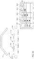
- FIGS. 1A and 1B illustrate an example system 100 to perform camera calibration according to some embodiments of the invention.
- System 100 provides a multi-camera approach for performing calibration, where a movable platform device (e.g., conveyer belt 104 ) includes multiple placement positions for multiple cameras.
- conveyer belt 104 includes four positions (positions 1, 2, 3, and 4) for four cameras 110 a - d to undergo concurrent calibration at any given moment in time.
- FIGS. 1A and 1B illustrates an example system 100 to perform camera calibration according to some embodiments of the invention.
- a movable platform device e.g., conveyer belt 104
- conveyer belt 104 includes four positions (positions 1, 2, 3, and 4) for four cameras 110 a - d to undergo concurrent calibration at any given moment in time.
- FIGS. 1A and 1B illustrates an example system 100 to perform camera calibration according to some embodiments of the invention.
- System 100 provides a multi-camera approach for performing calibration, where a movable platform device (
- the target 102 comprises a generally partial-spherical shape having multiple planar targets portions located thereon.
- a full-FOV (field of view) target ensures that all sections of the imager are covered by detectable points, where the imager corresponds to the sensor (e.g., CMOS or CCD sensor) inside the camera that converts the incoming light into digital output signals.
- the target 102 comprises a tessellated-sphere target having a spherical radius that is set at the focal distance of the cameras 110 a - d.
- cameras to be calibrated are loaded onto the conveyer belt 104 from an input stack 112 .
- a plurality of cameras are positioned on the conveyer belt 104 .
- Each of the cameras are located at a designated position, spaced apart from one another at a set distance, with their image capture direction facing the target 102 .
- the conveyer belt 104 operates to shift the location of the cameras from the direction of the input stack 112 to the direction of the output stack 114 .
- the movement of the conveyer belt 104 is paused when the cameras reach set positions for calibration. As shown in this figure, the conveyer belt 104 is paused when camera 110 d is located as position 1, camera 110 c is located at position 2, camera 110 b is located at position 3, and camera 110 a is located at position 4.
- each camera at its respective position then captures an image of the target 102 .
- the conveyer moves again such that the cameras shift to their next succeeding positions to capture another image of the target 102 .
- each camera will successively capture an image of the target 102 from each of the positions 1, 2, 3, and 4.
- the next shifting of its position will cause that camera to be placed into the output stack 114 .
- the images captured by the cameras include some or all of the marker planes within the target 102 .
- calculations are performed from the contents of the captured images to calibrate the cameras, e.g., by determining the intrinsic and extrinsic parameters for the cameras.
- FIG. 2 provides an illustration of the interior of a target 102 according to some embodiments of the invention.
- the target 102 is a multi-faceted structure comprised of multiple planar regions, where each facet/planar region 202 includes a respective planar target.
- the planar target is implemented as a Charuco or Aruco target.
- Example Aruco markers are illustrated in FIG. 3A .
- the main difference between Aruco/Charuco targets and the typical checkerboard target is that the Aruco/Charuco targets includes individual markers that are distinct from one another.
- Each of the Aruco/Charuco targets include patterns/markers that uniquely identify a given marker and its position in space. Since the Aruco/Charuco targets are composed of individual markers, this means that the camera does not need to see the entirety of the target in its complete form in order to obtain calibration points. Instead, the camera can only partially capture the image of the target and still be able to perform calibration from that target.
- the Charuco target combines the individual marker aspect of the Aruco target with the use of a checkerboard. This approach serves to improve localization determinations for certain types of calculations.
- FIG. 3B illustrates an example Charuco target 316 .
- Charuco or Aruco targets ensures that an image capture remains valid even if the entire target is not in frame. This may occur, for example, if a series of cameras were continuously being moved past a stationary target as illustrated in FIGS. 1A-B .
- This aspect of some embodiments of the invention therefore provides a distinct advantage over alternative approaches that use standard checkerboard targets, which require precise registration of the camera(s), as well as tightly controlled lighting, due to the need to have all targets and sub-elements clearly visible in each shot.
- FIGS. 4A-C illustrate the framework for a target 102 according some embodiments of the invention.
- FIG. 4A is a front view of the target 102 , looking into the concave/spherical interior of the target 102 .
- a plurality of faceted/tessellated planar portions 404 are stacked edge-to-edge at consistent angular transitions to form the target 102 .
- Each of the faceted planar portions 404 may be formed as a hexagonal structure, although other polygonal shapes are also within the scope of the invention.
- the angle of the joining between each of the faceted planar portions 404 is determined by the desired radius of the overall partial-spherical shape for the target 102 . As previously noted, in one embodiment, the radius is configured to generally match the focal distance of the cameras being calibrated.
- the size of the faceted planar portions 404 is determined by the desired overall size of the Charuco or Aruco target to be placed onto each facet and/or the number of individual markers to be placed onto each facet.
- FIGS. 4B and 4C show a mounting bracket 402 that is attached to the back of the target 102 to mount the target 102 at a given position and orientation relative to the conveyer belt. It is noted that since the cameras on the conveyer belt are capable of moving relative to the target 102 , this means that the target does not need to be positionally adjusted during the calibration process to permit the cameras to capture images of the target from multiple poses. Therefore, mounting bracket 402 can be configured as a locked-position bracket that is both structurally strong as well as efficiently manufacturable.
- Brackets 406 are employed to attach each planar portion to its adjacent planar portion. These brackets 406 comprise any suitable configuration that can serve to securely hold one planar portion in a fixed position relative to its neighboring planar portion. In some embodiments, bracket 406 comprises an angled indented shape to mount the planar portions 404 at the appropriate join angle relative to its neighboring planar portion.
- FIG. 5 illustrates an embodiment of a calibration system 500 having a backlighted target 102 , where one or more light sources 502 are provided to as a backlight to target 102 .
- the gain and exposure settings can be reduced to their minimum settings on a camera under test, resulting in a low-noise, motion-stable image for calibration. With sufficient intensity, this also serves to mask non-illuminated elements from the image, which increases the robustness of marker detection and/or reduces motion blur.
- the target is opaque, although other embodiments may employ targets having a range of different transparency levels.
- specularity is significantly reduced and/or entirely eliminated. This is because specularity generally occurs from outside reflections, which may wash out perception of the images of the target, e.g., where a white “smear” across the image occurs during the calibration process. Since the backlighted target is relatively bright, this permits the camera exposure to be a low enough level such that the only detectable illumination is from the target, which significantly minimizes any specularity. In addition, the entire calibration process can be performed faster, due to increased detection speed from the faster exposure settings, which serves to increase the throughput of the overall calibration system.
- FIG. 6 illustrates an example approach where an array 602 of multiple rows of cameras are placed onto one or more conveyer belts to capture images of the target 102 .
- the target 102 is positioned and/or configured to ensure that the focal point of the cameras in the array 602 are properly oriented at the target 602 . Since each camera is at a known location and offset from each planar target surface of the target 102 , this means that the techniques described herein are fully usable to perform calibration in this embodiment.
- FIG. 7 shows a flowchart of an approach to perform camera calibration using the apparatus and system described above.
- a camera is loaded onto the conveyer apparatus at a designed position on the conveyer apparatus.
- the cameras to be calibrated may be loaded onto the conveyer belt from an input stack, where at any given moment in time, a plurality of cameras are potentially positioned on the conveyer apparatus.
- Each of the cameras are located at a designated position, spaced apart from one another at a specified distance, with their image capture direction facing the target.
- an image is captured of the target from each of the cameras on the conveyer apparatus.
- the conveyer apparatus is used to move the location(s) of the cameras to each of the image capture positions in sequence. Therefore, a move-pause-image capture-move again cycle is repeated until each camera has taken an image from each designated position.
- the captured images are stored in a computer readable medium. Calibration analysis can then be performed on image data to generate calibration parameters for the camera devices. Thereafter, at 710 , the calibrated camera can be offloaded from the conveyer apparatus onto an output stack.
- FIGS. 8A through 8S provide an illustrative example for this calibration process according to some embodiments of the invention.
- FIG. 8A shows an example system to perform camera calibration that includes a conveyer belt 104 having multiple placement positions for multiple cameras.
- the conveyer belt 104 is configured to have four positions 1, 2, 3, and 4 to concurrently support four cameras for calibration.
- the target 102 comprises a generally partial-spherical shape having multiple planar targets portions where some or all of the planar target portions include an Aruco and/or Charuco target.
- a database 622 is configured to hold the image data to be captured by cameras undergoing calibration in the calibration system.
- the database 622 comprises a data structure that includes data portions to individually store image data content for images to be captured at each appropriate position on the conveyer belt 104 .
- the database 622 includes a portion 624 - 1 to hold image data for position 1, a portion 624 - 2 to hold image data for position 2, a portion 624 - 3 to hold image data for position 3, and a portion 624 - 4 to hold image data for position 4.
- a camera 610 a to be calibrated is loaded onto the conveyer belt 104 (e.g., from an input stack). For the sake of illustration, it is assumed that at this moment in time, there were no other cameras that had been previously loaded onto the conveyer belt 104 . However, it is noted that if calibration for other cameras were already in progress, then at the time frame shown in FIG. 8B , other cameras would also be shown on the conveyer belt 104 .
- FIG. 8C illustrates the movement of the conveyer belt 104 shifting the camera 610 a into position 1.
- the conveyer belt 104 pauses to allow the camera 610 a to capture an image of the target 102 .
- the image captured by the cameras 610 a includes some or all of the markers within the Aruco/Charuco targets within the target 102 .
- the captured image is stored in database 622 .
- an entry is created in database 622 for camera 610 a , and location 624 - 1 within that entry for camera 610 a is employed to store the captured image data for position 1.
- the conveyer belt 104 begins moving again to shift camera 610 a into a new position.
- the next camera 610 b to be calibrated is also loaded onto the conveyer belt 104 .
- Each of the cameras 610 a and 610 b that are concurrently placed onto the conveyer belt are located at designated positions that are spaced apart from one another at a pre-determined distance.
- FIG. 8G illustrates the movement of the conveyer belt 104 to shift the cameras 610 a and 610 b into positions 1 and 2, respectively.
- the conveyer belt 104 pauses to allow the cameras 610 a and 610 b to capture images of the target 102 from their respective positions.
- the captured images are then stored into database 622 .
- the new image is stored into the same entry that had already been created for this camera within database 622 , but the new image is placed into location 624 - 2 within that entry to store the captured image data for position 2.
- location 624 - 2 within that entry to store the captured image data for position 2.
- camera 610 b a new entry is created within database 622 for this camera, and the captured image is stored within location 624 - 1 for that new entry.
- the conveyer belt 104 begins moving again to shift cameras 610 a and 610 b into new positions.
- the next camera 610 c to be calibrated is loaded onto the conveyer belt 104 at this point.
- each of the cameras 610 a , 610 b , and 610 c that are concurrently placed onto the conveyer belt are located at designated positions that are spaced apart from one another at pre-determined distances.
- FIG. 8K shows the movement of the conveyer belt 104 to correspondingly move the cameras 610 a , 610 b , and 610 c into positions 1, 2 and 3, respectively.
- the conveyer belt 104 pauses to allow the cameras 610 a , 610 b , and 610 c to capture images of the target 102 from their respective positions.
- the captured images for the cameras 610 a , 610 b , and 610 c are then stored into database 622 .
- the new image is stored into the same entry that had already been created for this camera within database 622 , but the new image is placed into location 624 - 3 within that entry to store the captured image data for position 3.
- the image data is stored into the same entry that had already been created for this camera 610 b within database 622 , but the new image is placed into location 624 - 2 within that entry to store the captured image data for position 2.
- a new entry is created within database 622 for this camera, and the captured image is stored within location 624 - 1 for that new entry for camera 610 c.
- FIG. 8N shows the movement of conveyer belt 104 to shift cameras 610 a , 610 b , and 610 c into their new positions.
- the next camera 610 d to be calibrated is also loaded onto the conveyer belt 104 .
- each of the cameras 610 a , 610 b , 610 c , and 610 d that are concurrently placed onto the conveyer belt are located at designated positions spaced apart from each another at pre-determined distances.
- FIG. 8O shows the movement of the conveyer belt 104 to move the cameras 610 a , 610 b , 610 c , and 610 d into positions 1, 2, 3 and 4, respectively.
- the conveyer belt 104 pauses to allow the cameras 610 a , 610 b , 610 c , and 610 d to capture images of the target 102 from their respective positions.
- the captured images for the cameras 610 a , 610 b , 610 c , and 610 d are then stored into database 622 .
- the new image is stored into the same entry as before for this camera, but the new image is placed into location 624 - 4 within that entry to store the captured image data for position 4.
- the image data is stored into the same entry that had already been created for this camera 610 b within database 622 , but the new image is placed into location 624 - 3 within that entry to store the captured image data for position 3.
- the image data is stored into the same entry that had already been created for this camera 610 c within database 622 , but the new image is placed into location 624 - 2 within that entry to store the captured image data for position 2.
- a new entry is created within database 622 , and the captured image is stored within location 624 - 1 for that new entry for camera 610 d.
- the conveyer belt now begins moving again to shift the positions of the cameras that are undergoing calibration. At this point, camera 610 a has captured an image from each of the positions 1-4. Therefore, as shown in FIG. 8R , camera 610 a can now be unloaded from the conveyer belt 104 .
- This approach therefore operated to automatically move each camera to its successively required position to capture an image of the target 102 .
- the conveyer moves again such that the cameras shift to their next succeeding positions to capture another image of the target 102 .
- each camera will successively capture an image of the target 102 from each of the positions 1, 2, 3, and 4.
- the next shifting of its position will cause that camera to be placed into the output stack 114 .
- the image data for camera 610 a can be processed by calibration module 802 to process the image data.
- the different visual patterns including, e.g., corner points of the checkerboard and marker images
- the different visual patterns are identifiable from the captured images, which are used to generate calibration results such as the intrinsic parameters and the extrinsic parameters.
- Control system 804 and calibration module 802 comprises any type of computing station that may be used to operate, interface with, or implement one or more hardware system, software applications, or a combination of hardware and software.
- Examples of such computing systems include for example, servers, workstations, personal computers, or remote computing terminals connected to a networked or cloud-based computing platform.
- the computing system may comprise one or more input devices for the user to provide operational control over the activities of the system, such as a mouse or keyboard to manipulate a pointing object.
- the computing system may also be associated with a display device, such as a display monitor, for displaying analysis results or a control interface.
- the image data and/or analysis results may be stored in a computer readable storage medium 620 .
- the computer readable storage medium 620 includes any combination of hardware and/or software that allows for ready access to the data that is located at the computer readable storage medium 620 .
- computer readable storage medium 620 could be implemented as computer memory and/or hard drive storage operatively managed by an operating system, and/or remote storage in a networked storage device, such as networked attached storage (NAS), storage area network (SAN), or cloud storage.
- NAS networked attached storage
- SAN storage area network
- cloud storage cloud storage.
- the computer readable storage medium 620 could also be implemented as an electronic database system having storage on persistent and/or non-persistent storage.
- FIG. 9 shows a flowchart of an approach to process the image data captured by a camera to perform calibration for that camera.
- a pinhole camera model can be used to calibrate a typical camera, where the goal of the calibration process is to identify the fundamental parameters associated with that camera.
- the camera calibration process in the present invention determines parameters of transformations between 3D space/coordinates and the various 2D images captured by the camera at the different positions.
- the image data is collected for the images captured by the camera at the different positions on the conveyer belt.
- these images were captured at known, pre-determined locations on the conveyer belt at known distances and offsets from the target 102 . While the illustrative system shows images captured from four positions, it is noted that depending upon the specific configuration of the calibration system and its components, any number of images may be suitably captured by a camera and used for calibration.
- Filtering and/or processing of the image data may occur at this point. For example, unwanted content from around the individual markers within the Aruco/Charuco targets (e.g., border content) may have been captured by the camera. Such content is unnecessary for calibration purposes and may therefore be discarded/filtered from the data set. In addition, any corrupt/erroneous content may also be filtered at this stage.
- markers are identified from the image data.
- Each marker within an Aruco/Charuco target is an individualized marker having its own individualized coding.
- a hamming code can be used to generate a unique signature for each marker within the targets.
- the specific pattern within a given marker is analyzed to see the exact position of each element within the marker, and the pattern is “decoded” to identify the specific marker at a specific location on a specific planar target surface of the semi-spherical target 102 .
- the intrinsic and extrinsic parameters for the camera are derived from the processed marker data. This is accomplished because the pre-defined knowledge of the location of the target means that the system can establish correspondence of the identified marker points in 3D space. In the current invention, the fact that there are multiple target planes, and the locations of all of these planes are known in relation to each other, provides numerous additional calibration points within the coordinate space. This therefore greatly facilitates precise and accurate estimation of the camera parameters. For example, when estimating the camera projection matrix, a linear solution can be acquired by performing linear estimations for each of the 2D-3D correspondences. It is noted that non-linear calculations may be used instead of, or in addition to, the linear estimations. For example, non-linear techniques may be employed to optimize the linear solutions.
- intrinsic parameters can be derived, such as for example: (a) the focal length of the camera in both the X and Y axes; (b) optical center of the camera (or camera sensor); and/or (c) distortion coefficients.
- Extrinsic parameters may also be derived for the camera. Reference data external to the camera would be obtained and used to determine the extrinsic parameters.
- the extrinsic parameters can be obtained as 3D rotations and 3D translations to translate the camera reference system to another reference system, e.g., relative to another camera in a two-camera stereoscopic system.
- calibration is finalized by storing the calibration parameters within an appropriate storage location on a computer readable medium.
- Embodiments of the present invention therefore solves the problems of the conventional approach that are too time consuming, computationally expensive, and just plainly ill-suited for high-volume manufacturing.
- FIG. 10 is a block diagram of an illustrative computing system 1400 suitable for implementing an embodiment of the present invention.
- Computer system 1400 includes a bus 1406 or other communication mechanism for communicating information, which interconnects subsystems and devices, such as processor 1407 , system memory 1408 (e.g., RAM), static storage device 1409 (e.g., ROM), disk drive 1410 (e.g., magnetic or optical), communication interface 1414 (e.g., modem or Ethernet card), display 1411 (e.g., CRT or LCD), input device 1412 (e.g., keyboard), and cursor control.
- processor 1407 e.g., system memory 1408 (e.g., RAM), static storage device 1409 (e.g., ROM), disk drive 1410 (e.g., magnetic or optical), communication interface 1414 (e.g., modem or Ethernet card), display 1411 (e.g., CRT or LCD), input device 1412 (e.g., keyboard), and cursor control.
- computer system 1400 performs specific operations by processor 1407 executing one or more sequences of one or more instructions contained in system memory 1408 .
- Such instructions may be read into system memory 1408 from another computer readable/usable medium, such as static storage device 1409 or disk drive 1410 .
- static storage device 1409 or disk drive 1410 may be used in place of or in combination with software instructions to implement the invention.
- hard-wired circuitry may be used in place of or in combination with software instructions to implement the invention.
- embodiments of the invention are not limited to any specific combination of hardware circuitry and/or software.
- the term “logic” shall mean any combination of software or hardware that is used to implement all or part of the invention.
- Non-volatile media includes, for example, optical or magnetic disks, such as disk drive 1410 .
- Volatile media includes dynamic memory, such as system memory 1408 .
- Computer readable media include, for example, floppy disk, flexible disk, hard disk, magnetic tape, any other magnetic medium, CD-ROM, any other optical medium, punch cards, paper tape, any other physical medium with patterns of holes, RAM, PROM, EPROM, FLASH-EPROM, any other memory chip or cartridge, or any other medium from which a computer can read.
- execution of the sequences of instructions to practice the invention is performed by a single computer system 1400 .
- two or more computer systems 1400 coupled by communication link 1415 may perform the sequence of instructions required to practice the invention in coordination with one another.
- Computer system 1400 may transmit and receive messages, data, and instructions, including program, e.g., application code, through communication link 1415 and communication interface 1414 .
- Received program code may be executed by processor 1407 as it is received, and/or stored in disk drive 1410 , or other non-volatile storage for later execution.
- Computer system 1400 may communicate through a data interface 1433 to a database 1432 on an external storage device 1431 .
Abstract
Description
Claims (19)
Priority Applications (1)
| Application Number | Priority Date | Filing Date | Title |
|---|---|---|---|
| US16/721,291 US11503275B2 (en) | 2016-06-28 | 2019-12-19 | Camera calibration system, target, and process |
Applications Claiming Priority (3)
| Application Number | Priority Date | Filing Date | Title |
|---|---|---|---|
| US201662355805P | 2016-06-28 | 2016-06-28 | |
| US15/635,120 US10547833B2 (en) | 2016-06-28 | 2017-06-27 | Camera calibration system, target, and process |
| US16/721,291 US11503275B2 (en) | 2016-06-28 | 2019-12-19 | Camera calibration system, target, and process |
Related Parent Applications (1)
| Application Number | Title | Priority Date | Filing Date |
|---|---|---|---|
| US15/635,120 Continuation US10547833B2 (en) | 2016-06-28 | 2017-06-27 | Camera calibration system, target, and process |
Publications (2)
| Publication Number | Publication Date |
|---|---|
| US20200128235A1 US20200128235A1 (en) | 2020-04-23 |
| US11503275B2 true US11503275B2 (en) | 2022-11-15 |
Family
ID=60675698
Family Applications (2)
| Application Number | Title | Priority Date | Filing Date |
|---|---|---|---|
| US15/635,120 Active US10547833B2 (en) | 2016-06-28 | 2017-06-27 | Camera calibration system, target, and process |
| US16/721,291 Active 2037-09-15 US11503275B2 (en) | 2016-06-28 | 2019-12-19 | Camera calibration system, target, and process |
Family Applications Before (1)
| Application Number | Title | Priority Date | Filing Date |
|---|---|---|---|
| US15/635,120 Active US10547833B2 (en) | 2016-06-28 | 2017-06-27 | Camera calibration system, target, and process |
Country Status (5)
| Country | Link |
|---|---|
| US (2) | US10547833B2 (en) |
| JP (2) | JP6821714B2 (en) |
| KR (2) | KR102487546B1 (en) |
| CN (2) | CN109416744B (en) |
| WO (1) | WO2018005561A1 (en) |
Families Citing this family (24)
| Publication number | Priority date | Publication date | Assignee | Title |
|---|---|---|---|---|
| DE102006004197A1 (en) * | 2006-01-26 | 2007-08-09 | Klett, Rolf, Dr.Dr. | Method and device for recording body movements |
| US10547833B2 (en) * | 2016-06-28 | 2020-01-28 | Magic Leap, Inc. | Camera calibration system, target, and process |
| US10675761B2 (en) | 2016-10-14 | 2020-06-09 | Magic Leap, Inc. | Mode architecture for general purpose robotics |
| DE102018215491A1 (en) * | 2018-09-12 | 2020-03-12 | Robert Bosch Gmbh | Procedure for calibrating an acquisition system |
| WO2020101892A1 (en) | 2018-11-12 | 2020-05-22 | Magic Leap, Inc. | Patch tracking image sensor |
| WO2020101895A1 (en) | 2018-11-12 | 2020-05-22 | Magic Leap, Inc. | Event-based camera with high-resolution frame output |
| US20220014689A1 (en) * | 2018-11-13 | 2022-01-13 | Magic Leap, Inc. | Event-based ir camera |
| EP3881232A4 (en) * | 2018-11-15 | 2022-08-10 | Magic Leap, Inc. | Deep neural network pose estimation system |
| DE102018222796A1 (en) * | 2018-12-21 | 2020-06-25 | Conti Temic Microelectronic Gmbh | Setup and measurement of the setup for calibrating a camera |
| US11889209B2 (en) | 2019-02-07 | 2024-01-30 | Magic Leap, Inc. | Lightweight cross reality device with passive depth extraction |
| IL264797B (en) * | 2019-02-12 | 2021-06-30 | Agent Video Intelligence Ltd | System and method for use in geo-spatial registration |
| US10925687B2 (en) * | 2019-07-12 | 2021-02-23 | Synaptive Medical Inc. | System and method for optical axis calibration |
| KR200491661Y1 (en) * | 2019-09-30 | 2020-05-14 | (주)이즈미디어 | Performance validation device for tof camera |
| KR200491660Y1 (en) * | 2019-09-30 | 2020-05-13 | (주)이즈미디어 | Calibration device for tof camera |
| CN110611770B (en) * | 2019-10-08 | 2021-07-30 | 凌云光技术股份有限公司 | Method and system for judging whether line frequency of linear array camera is matched with object motion speed |
| CN111758120A (en) * | 2019-10-18 | 2020-10-09 | 深圳市大疆创新科技有限公司 | Calibration method and system of camera device, three-dimensional calibration device and storage medium |
| CN113330487A (en) * | 2019-12-30 | 2021-08-31 | 华为技术有限公司 | Parameter calibration method and device |
| USD918944S1 (en) * | 2020-05-01 | 2021-05-11 | 3M Innovative Properties Company | Display screen with transitional graphical user interface |
| JP2023525508A (en) * | 2020-05-06 | 2023-06-16 | マジック リープ, インコーポレイテッド | Convolution-based camera and display calibration |
| CN111815719B (en) * | 2020-07-20 | 2023-12-22 | 阿波罗智能技术(北京)有限公司 | External parameter calibration method, device and equipment of image acquisition equipment and storage medium |
| WO2022026609A1 (en) * | 2020-07-29 | 2022-02-03 | Magic Leap, Inc. | Camera extrinsic calibration via ray intersections |
| DE102020212279B3 (en) * | 2020-09-29 | 2021-10-28 | Myestro Interactive Gmbh | Device for calibrating a spatial position of a center of an entrance pupil of a camera, calibration method for this, and a system for determining the relative position of centers of entrance pupils of at least two cameras, which are mounted on a common support frame, to one another, and determination methods for this |
| DE102020212635A1 (en) | 2020-10-07 | 2022-04-07 | Robert Bosch Gesellschaft mit beschränkter Haftung | Procedure for calibrating a camera |
| WO2022113582A1 (en) * | 2020-11-30 | 2022-06-02 | 日本電気株式会社 | Calibration method, calibration device, calibration system, and recording medium |
Citations (11)
| Publication number | Priority date | Publication date | Assignee | Title |
|---|---|---|---|---|
| US6009359A (en) | 1996-09-18 | 1999-12-28 | National Research Council Of Canada | Mobile system for indoor 3-D mapping and creating virtual environments |
| US20040160512A1 (en) | 2003-02-14 | 2004-08-19 | Lee Charles C. | 3D camera system and method |
| US20060125921A1 (en) | 1999-08-09 | 2006-06-15 | Fuji Xerox Co., Ltd. | Method and system for compensating for parallax in multiple camera systems |
| US20080259179A1 (en) | 2005-03-07 | 2008-10-23 | International Business Machines Corporation | Automatic Multiscale Image Acquisition from a Steerable Camera |
| US20100098327A1 (en) | 2005-02-11 | 2010-04-22 | Mas Donald Dettwiler And Associates Inc. | 3D Imaging system |
| US9001226B1 (en) | 2012-12-04 | 2015-04-07 | Lytro, Inc. | Capturing and relighting images using multiple devices |
| WO2015134958A1 (en) | 2014-03-07 | 2015-09-11 | Magic Leap, Inc. | Virtual and augmented reality systems and methods |
| US20150294483A1 (en) | 2014-04-10 | 2015-10-15 | GM Global Technology Operations LLC | Vision-based multi-camera factory monitoring with dynamic integrity scoring |
| US20160182903A1 (en) * | 2014-12-19 | 2016-06-23 | Disney Enterprises, Inc. | Camera calibration |
| US20160373734A1 (en) | 2015-02-24 | 2016-12-22 | Nextvr Inc. | Methods and apparatus related to capturing and/or rendering images |
| KR102261020B1 (en) | 2016-06-28 | 2021-06-03 | 매직 립, 인코포레이티드 | Improved camera calibration system, target and process |
Family Cites Families (12)
| Publication number | Priority date | Publication date | Assignee | Title |
|---|---|---|---|---|
| JP4307050B2 (en) | 2002-11-07 | 2009-08-05 | 富士通株式会社 | Highlight scene extraction device |
| JP3735344B2 (en) | 2002-12-27 | 2006-01-18 | オリンパス株式会社 | Calibration apparatus, calibration method, and calibration program |
| JP2006121750A (en) * | 2006-01-06 | 2006-05-11 | Olympus Corp | Calibration pattern unit |
| JP2007135218A (en) * | 2006-11-22 | 2007-05-31 | Matsushita Electric Ind Co Ltd | Camera apparatus, and system and method for camera calibration |
| US20110222757A1 (en) * | 2010-03-10 | 2011-09-15 | Gbo 3D Technology Pte. Ltd. | Systems and methods for 2D image and spatial data capture for 3D stereo imaging |
| JP6164679B2 (en) | 2012-10-30 | 2017-07-19 | 株式会社Halデザイン研究所 | Camera calibration method and camera calibration apparatus |
| US10032273B2 (en) * | 2013-03-15 | 2018-07-24 | Cognex Corporation | Machine vision system calibration using inaccurate calibration targets |
| JP2014204198A (en) * | 2013-04-02 | 2014-10-27 | キヤノン株式会社 | Image processing device, control method thereof and program |
| US9430822B2 (en) * | 2013-06-14 | 2016-08-30 | Microsoft Technology Licensing, Llc | Mobile imaging platform calibration |
| US9210417B2 (en) * | 2013-07-17 | 2015-12-08 | Microsoft Technology Licensing, Llc | Real-time registration of a stereo depth camera array |
| US9641830B2 (en) | 2014-04-08 | 2017-05-02 | Lucasfilm Entertainment Company Ltd. | Automated camera calibration methods and systems |
| JP6569742B2 (en) * | 2016-01-13 | 2019-09-04 | 株式会社リコー | Projection system, image processing apparatus, projection method, and program |
-
2017
- 2017-06-27 US US15/635,120 patent/US10547833B2/en active Active
- 2017-06-27 JP JP2018567814A patent/JP6821714B2/en active Active
- 2017-06-27 CN CN201780039520.5A patent/CN109416744B/en active Active
- 2017-06-27 CN CN202311560374.4A patent/CN117596385A/en active Pending
- 2017-06-27 KR KR1020217016447A patent/KR102487546B1/en active IP Right Grant
- 2017-06-27 WO PCT/US2017/039600 patent/WO2018005561A1/en active Application Filing
- 2017-06-27 KR KR1020197001581A patent/KR102261020B1/en active IP Right Grant
-
2019
- 2019-12-19 US US16/721,291 patent/US11503275B2/en active Active
-
2021
- 2021-01-06 JP JP2021000726A patent/JP7057454B2/en active Active
Patent Citations (11)
| Publication number | Priority date | Publication date | Assignee | Title |
|---|---|---|---|---|
| US6009359A (en) | 1996-09-18 | 1999-12-28 | National Research Council Of Canada | Mobile system for indoor 3-D mapping and creating virtual environments |
| US20060125921A1 (en) | 1999-08-09 | 2006-06-15 | Fuji Xerox Co., Ltd. | Method and system for compensating for parallax in multiple camera systems |
| US20040160512A1 (en) | 2003-02-14 | 2004-08-19 | Lee Charles C. | 3D camera system and method |
| US20100098327A1 (en) | 2005-02-11 | 2010-04-22 | Mas Donald Dettwiler And Associates Inc. | 3D Imaging system |
| US20080259179A1 (en) | 2005-03-07 | 2008-10-23 | International Business Machines Corporation | Automatic Multiscale Image Acquisition from a Steerable Camera |
| US9001226B1 (en) | 2012-12-04 | 2015-04-07 | Lytro, Inc. | Capturing and relighting images using multiple devices |
| WO2015134958A1 (en) | 2014-03-07 | 2015-09-11 | Magic Leap, Inc. | Virtual and augmented reality systems and methods |
| US20150294483A1 (en) | 2014-04-10 | 2015-10-15 | GM Global Technology Operations LLC | Vision-based multi-camera factory monitoring with dynamic integrity scoring |
| US20160182903A1 (en) * | 2014-12-19 | 2016-06-23 | Disney Enterprises, Inc. | Camera calibration |
| US20160373734A1 (en) | 2015-02-24 | 2016-12-22 | Nextvr Inc. | Methods and apparatus related to capturing and/or rendering images |
| KR102261020B1 (en) | 2016-06-28 | 2021-06-03 | 매직 립, 인코포레이티드 | Improved camera calibration system, target and process |
Non-Patent Citations (15)
| Title |
|---|
| Amendment Response to NFOA for U.S. Appl. No. 15/635,120 dated Apr. 24, 2019. |
| Amendment Response to NFOA for U.S. Appl. No. 15/635,120 dated Oct. 1, 2018. |
| Foreign NOA for JP Patent Application No. 2018-567814 dated Dec. 9, 2020. |
| Foreign NOA for JP Patent Appln. No. 2021-726 dated Mar. 9, 2022. |
| Foreign NOA for KR Patent Appln. No. 10-2019-7001581 dated Mar. 2, 2021. |
| Foreign OA for KR Patent Appln. No. 10-2021-7016447 dated Apr. 6, 2022 (with English translation). |
| Foreign OA Response for JP Patent Application No. 2018-567814 dated Nov. 26, 2020. |
| Foreign Office Action for JP Patent Appln. No. 2018-567814 dated Aug. 31, 2020. |
| Foreign Office Action for KR Patent Appln. No. 10-2019-7001581 dated Nov. 2, 2020. |
| Foreign Response for KR Patent Appln. No. 10-2019-7001581 dated Jan. 4, 2021. |
| Foreign Response for KR Patent Appln. No. 10-2021-7016447 dated May 31, 2022. |
| International Search Report and Written Opinion dated Sep. 8, 2017 for PCT App No. PCT/US2017/039600, 9 pgs. |
| Non-Final Office Action for U.S. Appl. No. 15/635,120 dated Jan. 24, 2019. |
| Non-Final Office Action for U.S. Appl. No. 15/635,120 dated Jun. 29, 2018. |
| Notice of Allowance for U.S. Appl. No. 15/635,120 dated Sep. 25, 2019. |
Also Published As
| Publication number | Publication date |
|---|---|
| US20200128235A1 (en) | 2020-04-23 |
| CN109416744A (en) | 2019-03-01 |
| JP2019530261A (en) | 2019-10-17 |
| CN109416744B (en) | 2023-12-15 |
| KR102487546B1 (en) | 2023-01-10 |
| JP2021072634A (en) | 2021-05-06 |
| WO2018005561A1 (en) | 2018-01-04 |
| CN117596385A (en) | 2024-02-23 |
| KR20210066031A (en) | 2021-06-04 |
| KR20190021342A (en) | 2019-03-05 |
| US10547833B2 (en) | 2020-01-28 |
| JP7057454B2 (en) | 2022-04-19 |
| KR102261020B1 (en) | 2021-06-03 |
| JP6821714B2 (en) | 2021-01-27 |
| US20170374360A1 (en) | 2017-12-28 |
Similar Documents
| Publication | Publication Date | Title |
|---|---|---|
| US11503275B2 (en) | Camera calibration system, target, and process | |
| CN111179358B (en) | Calibration method, device, equipment and storage medium | |
| CN105453546B (en) | Image processing apparatus, image processing system and image processing method | |
| CN109584307B (en) | System and method for improving calibration of intrinsic parameters of a camera | |
| US7554575B2 (en) | Fast imaging system calibration | |
| US20190132584A1 (en) | Method and device for calibration | |
| US11720766B2 (en) | Systems and methods for text and barcode reading under perspective distortion | |
| CN110809786B (en) | Calibration device, calibration chart, chart pattern generation device, and calibration method | |
| JP5580164B2 (en) | Optical information processing apparatus, optical information processing method, optical information processing system, and optical information processing program | |
| KR101121034B1 (en) | System and method for obtaining camera parameters from multiple images and computer program products thereof | |
| CN107155341B (en) | Three-dimensional scanning system and frame | |
| US8797387B2 (en) | Self calibrating stereo camera | |
| CN113034612B (en) | Calibration device, method and depth camera | |
| CN109247068A (en) | Method and apparatus for rolling shutter compensation | |
| EP3144894B1 (en) | Method and system for calibrating an image acquisition device and corresponding computer program product | |
| WO2013149866A2 (en) | Method and device for transforming an image | |
| CN112749664A (en) | Gesture recognition method, device, equipment, system and storage medium | |
| CN111489384A (en) | Occlusion assessment method, device, equipment, system and medium based on mutual view | |
| RU2722412C1 (en) | Method for stereo calibration of different-spectral cameras with small angular cross-section of fields of vision | |
| JP7312594B2 (en) | Calibration charts and calibration equipment | |
| CN117058520A (en) | Three-dimensional panoramic image scene structure identification method, system, equipment and storage medium | |
| CN113837927A (en) | Standing tree height measuring system and method based on machine vision |
Legal Events
| Date | Code | Title | Description |
|---|---|---|---|
| AS | Assignment |
Owner name: MAGIC LEAP, INC., FLORIDA Free format text: ASSIGNMENT OF ASSIGNORS INTEREST;ASSIGNORS:KRANSKI, JEFFREY STEVEN;ZYDA, FREDERICK DENNIS;VESOM, GRACE;AND OTHERS;SIGNING DATES FROM 20140311 TO 20160718;REEL/FRAME:051336/0656 |
|
| FEPP | Fee payment procedure |
Free format text: ENTITY STATUS SET TO UNDISCOUNTED (ORIGINAL EVENT CODE: BIG.); ENTITY STATUS OF PATENT OWNER: LARGE ENTITY |
|
| AS | Assignment |
Owner name: CITIBANK, N.A., AS COLLATERAL AGENT, NEW YORK Free format text: SECURITY INTEREST;ASSIGNORS:MAGIC LEAP, INC.;MOLECULAR IMPRINTS, INC.;MENTOR ACQUISITION ONE, LLC;REEL/FRAME:052729/0791 Effective date: 20200521 |
|
| STPP | Information on status: patent application and granting procedure in general |
Free format text: DOCKETED NEW CASE - READY FOR EXAMINATION |
|
| STPP | Information on status: patent application and granting procedure in general |
Free format text: NON FINAL ACTION MAILED |
|
| STPP | Information on status: patent application and granting procedure in general |
Free format text: RESPONSE TO NON-FINAL OFFICE ACTION ENTERED AND FORWARDED TO EXAMINER |
|
| STPP | Information on status: patent application and granting procedure in general |
Free format text: NON FINAL ACTION MAILED |
|
| STPP | Information on status: patent application and granting procedure in general |
Free format text: RESPONSE TO NON-FINAL OFFICE ACTION ENTERED AND FORWARDED TO EXAMINER |
|
| AS | Assignment |
Owner name: CITIBANK, N.A., AS COLLATERAL AGENT, NEW YORK Free format text: SECURITY INTEREST;ASSIGNORS:MOLECULAR IMPRINTS, INC.;MENTOR ACQUISITION ONE, LLC;MAGIC LEAP, INC.;REEL/FRAME:060338/0665 Effective date: 20220504 |
|
| STPP | Information on status: patent application and granting procedure in general |
Free format text: NOTICE OF ALLOWANCE MAILED -- APPLICATION RECEIVED IN OFFICE OF PUBLICATIONS |
|
| STPP | Information on status: patent application and granting procedure in general |
Free format text: DOCKETED NEW CASE - READY FOR EXAMINATION |
|
| STPP | Information on status: patent application and granting procedure in general |
Free format text: NOTICE OF ALLOWANCE MAILED -- APPLICATION RECEIVED IN OFFICE OF PUBLICATIONS |
|
| STPP | Information on status: patent application and granting procedure in general |
Free format text: PUBLICATIONS -- ISSUE FEE PAYMENT VERIFIED |
|
| STCF | Information on status: patent grant |
Free format text: PATENTED CASE |
|
| AS | Assignment |
Owner name: CITIBANK, N.A., AS COLLATERAL AGENT, NEW YORK Free format text: SECURITY INTEREST;ASSIGNORS:MAGIC LEAP, INC.;MENTOR ACQUISITION ONE, LLC;MOLECULAR IMPRINTS, INC.;REEL/FRAME:062681/0065 Effective date: 20230201 |