EP3144437A1 - Module assembly for a building - Google Patents
Module assembly for a building Download PDFInfo
- Publication number
- EP3144437A1 EP3144437A1 EP16189386.2A EP16189386A EP3144437A1 EP 3144437 A1 EP3144437 A1 EP 3144437A1 EP 16189386 A EP16189386 A EP 16189386A EP 3144437 A1 EP3144437 A1 EP 3144437A1
- Authority
- EP
- European Patent Office
- Prior art keywords
- module
- panel
- frame
- side panel
- seal
- Prior art date
- Legal status (The legal status is an assumption and is not a legal conclusion. Google has not performed a legal analysis and makes no representation as to the accuracy of the status listed.)
- Withdrawn
Links
- 230000015572 biosynthetic process Effects 0.000 claims description 79
- 238000005755 formation reaction Methods 0.000 claims description 79
- 238000001125 extrusion Methods 0.000 claims description 40
- 230000001413 cellular effect Effects 0.000 claims description 3
- 238000000034 method Methods 0.000 claims description 2
- 239000002861 polymer material Substances 0.000 claims description 2
- 238000000429 assembly Methods 0.000 description 13
- 230000000712 assembly Effects 0.000 description 12
- 239000004743 Polypropylene Substances 0.000 description 4
- 238000007789 sealing Methods 0.000 description 4
- 238000010276 construction Methods 0.000 description 3
- 239000006260 foam Substances 0.000 description 3
- -1 polypropylene Polymers 0.000 description 3
- 229910000831 Steel Inorganic materials 0.000 description 2
- XAGFODPZIPBFFR-UHFFFAOYSA-N aluminium Chemical compound [Al] XAGFODPZIPBFFR-UHFFFAOYSA-N 0.000 description 2
- 229910052782 aluminium Inorganic materials 0.000 description 2
- 239000004411 aluminium Substances 0.000 description 2
- 238000004519 manufacturing process Methods 0.000 description 2
- 239000000463 material Substances 0.000 description 2
- 229920001155 polypropylene Polymers 0.000 description 2
- 239000010959 steel Substances 0.000 description 2
- 239000000654 additive Substances 0.000 description 1
- 230000000996 additive effect Effects 0.000 description 1
- 238000004378 air conditioning Methods 0.000 description 1
- 238000004891 communication Methods 0.000 description 1
- 239000002131 composite material Substances 0.000 description 1
- 230000007423 decrease Effects 0.000 description 1
- 230000009977 dual effect Effects 0.000 description 1
- 239000003365 glass fiber Substances 0.000 description 1
- 238000010438 heat treatment Methods 0.000 description 1
- 238000009413 insulation Methods 0.000 description 1
- 239000012528 membrane Substances 0.000 description 1
- 239000004033 plastic Substances 0.000 description 1
- 229920003023 plastic Polymers 0.000 description 1
- 239000007787 solid Substances 0.000 description 1
- 239000003351 stiffener Substances 0.000 description 1
Images


Classifications
-
- E—FIXED CONSTRUCTIONS
- E04—BUILDING
- E04B—GENERAL BUILDING CONSTRUCTIONS; WALLS, e.g. PARTITIONS; ROOFS; FLOORS; CEILINGS; INSULATION OR OTHER PROTECTION OF BUILDINGS
- E04B1/00—Constructions in general; Structures which are not restricted either to walls, e.g. partitions, or floors or ceilings or roofs
- E04B1/343—Structures characterised by movable, separable, or collapsible parts, e.g. for transport
- E04B1/344—Structures characterised by movable, separable, or collapsible parts, e.g. for transport with hinged parts
- E04B1/3442—Structures characterised by movable, separable, or collapsible parts, e.g. for transport with hinged parts folding out from a core cell
- E04B1/3444—Structures characterised by movable, separable, or collapsible parts, e.g. for transport with hinged parts folding out from a core cell with only lateral unfolding
-
- E—FIXED CONSTRUCTIONS
- E04—BUILDING
- E04B—GENERAL BUILDING CONSTRUCTIONS; WALLS, e.g. PARTITIONS; ROOFS; FLOORS; CEILINGS; INSULATION OR OTHER PROTECTION OF BUILDINGS
- E04B2/00—Walls, e.g. partitions, for buildings; Wall construction with regard to insulation; Connections specially adapted to walls
- E04B2/72—Non-load-bearing walls of elements of relatively thin form with respect to the thickness of the wall
-
- E—FIXED CONSTRUCTIONS
- E04—BUILDING
- E04B—GENERAL BUILDING CONSTRUCTIONS; WALLS, e.g. PARTITIONS; ROOFS; FLOORS; CEILINGS; INSULATION OR OTHER PROTECTION OF BUILDINGS
- E04B2/00—Walls, e.g. partitions, for buildings; Wall construction with regard to insulation; Connections specially adapted to walls
- E04B2/74—Removable non-load-bearing partitions; Partitions with a free upper edge
- E04B2/7407—Removable non-load-bearing partitions; Partitions with a free upper edge assembled using frames with infill panels or coverings only; made-up of panels and a support structure incorporating posts
- E04B2/7416—Removable non-load-bearing partitions; Partitions with a free upper edge assembled using frames with infill panels or coverings only; made-up of panels and a support structure incorporating posts with free upper edge, e.g. for use as office space dividers
- E04B2/7422—Removable non-load-bearing partitions; Partitions with a free upper edge assembled using frames with infill panels or coverings only; made-up of panels and a support structure incorporating posts with free upper edge, e.g. for use as office space dividers with separate framed panels without intermediary support posts
- E04B2/7427—Removable non-load-bearing partitions; Partitions with a free upper edge assembled using frames with infill panels or coverings only; made-up of panels and a support structure incorporating posts with free upper edge, e.g. for use as office space dividers with separate framed panels without intermediary support posts with adjustable angular connection of panels
Definitions
- the present invention relates to module assemblies for the construction of modular buildings. More specifically, the present invention relates to assemblies of modules for modular buildings for human occupancy, which modules can be transported in a collapsed configuration and erected at a desired site.
- Modular buildings are known in the art, and are used in a wide range of situations. Such buildings are usually employed where temporary use is desirable. For example, in a building site it is often useful to set up temporary offices and premises where work can be undertaken whilst the permanent building is being constructed. Similarly in military environments, temporary construction of offices and dwellings for military personal is desirable.
- the buildings need to be easily transported taking up the minimum amount of space.
- Known temporary buildings are therefore constructed of several fold-flat modules which can be assembled together in at least one configuration.
- the buildings need to be easily erected and dismantled, using the minimum number of tools. Preferably, no specialist tools should be required.
- the buildings need to be well sealed, in the event that the environment is hostile (for example sandy), or in the event that heating or air conditioning is to be used. Therefore the ability to made as air- and water-tight as possible is desirable.
- the buildings need to be modular in nature-that is the sub-assemblies should be suitable for assembly in a variety of different configurations. In this manner, part count is reduced, and the modules can be used to construct a variety of buildings, from small stores, to offices, to officers' quarters, to full barracks as required.
- a known modular building is disclosed in GB2286337A .
- the building comprises at least three side members connected by pin and slot joints.
- the building is configurable between a collapsed and erected configuration.
- a further known modular building is disclosed in US5904005 .
- the building comprises a plurality of modular units, each of which has a central frame and four walls arranged in opposing pairs to give an I-shaped configuration. One pair of walls may be extended with the other flat against the frame to provide a [or] shaped configuration.
- modules of US'005 can only be arranged in an end-to-end formation-i.e. where the central frames are spaced apart and offset from each other. Therefore the user is constrained as to the configuration of the buildings which can be constructed.
- the only option is to form buildings with an Nx1 module arrangement. The only way to make the building larger is to make it longer, which may a problem considering the intended use and / or external space restrictions.
- NxM configurations i.e. N modules long by M modules wide.
- a modular building assembly comprising:
- the inter-panel seal engaging formations and the inter-panel seal are configured such that the inter-panel seal can only be inserted and removed in a direction parallel to the side of each first side panel on which the inter-panel seal receiving formation is defined. In use, this is the vertical direction.
- this inhibits seal opening by accidental impact, building movement etc. and provides for a better seal.
- each inter-panel seal receiving formation defines an undercut recess in the respective first side panel, and in which the inter-panel seal defines a flange at either end for engagement in the undercut recess.
- this prevents pull-out of the seal from the formation (apart from in the intended axial direction).
- the flanges of the inter-panel seal are joined by a seal body, in which the flanges are stiffer than the seal. This provides the dual functionality of providing secure engagement with the panels, but provides a flexible seal which allows for inter-panel movement in use.
- inter-panel seal engaging formation of the first module first side panel and the inter-panel seal engaging formation of the second module first side panel are configured to have an uninterrupted line of sight there between before the inter-panel seal is inserted.
- this allows easy assembly and disassembly of the seal.
- each first side panel defines an adjacent pair of inter-panel seal engaging formations, and in which two adjacent inter-panel seals are provided between each first side panel. This provides redundancy, and a better seal.
- each of the pair of inter-panel seal engaging formations is positioned either side of a central plane of the respective first side panel.
- each first side panel further defines a frame seal engaging formation facing the respective first or second module frame. This allows the panel to seal against the frame as well (when required).
- the frame seal engaging formations face in a direction normal to the respective inter-panel seal engaging formations.
- each of the first and second module first side panels is pivotably mounted to the respective frame. This allows for easy opening and closure.
- This configuration allows for a wide range of building formations.
- each of the second side panels is identical to each of the first side panels.
- each first and second side panels is rotatable about a respective first and second panel axis, in which the first panel axis is at a first end of the frame, and the second panel axis is at a second end of the frame such that the respective frame and panels can form a "Z" shape.
- This configuration allows for a wide range of building formations.
- each of the side panels comprises a panel member and an edge member attached to opposite edges of the panel member, which edge members define the inter-panel seal engaging formation or formations. This allows the load bearing / seal bearing parts of the panel to be stiff, and the main panel to be light.
- edge members are extrusions defining the inter-panel seal engaging formation or formations parallel to an axis of extrusion.
- Extrusions are inexpensive to manufacture, and such formations are well suited to aluminium which is an ideal material due to its strength and low density.
- edge members define one side of a rotational joint to facilitate rotation of the side panel from the stowed and deployed positions.
- the side panels comprise a cellular core with an outer skin, which provides a stiff but light structure.
- the cellular core and outer skin are constructed from a thermally bonded polymer material.
- a module 100 generally comprising a frame 102, a first panel assembly 104 and a second panel assembly 106 mounted on either side of the frame 102.
- the module 100 is generally rectangular and planar, and is shown in Figures 1A to 1C in a folded, flat configuration for storage and transportation in which the first and second panel assemblies 104, 106 overlie opposite sides of the frame 102.
- the frame 102 is shown without the panel assemblies 104, 106.
- the frame 102 is a generally rectangular endless loop in shape, comprising horizontal top and bottom members 108, 110 respectively and vertical side members 112, 114.
- the top and bottom members 108, 110 are closed section rectangular steel tubes.
- the side members are rectangular steel tubes with internally-facing channels 116, the channels 116 running longitudinally along the members 112, 114.
- the channels 116 can be used for routing e.g. electrical cables.
- a frame plane FP lies halfway through the thickness of the frame 102.
- first and second fixed hinge plates 120, 122 are flat rectangular plates which extend normal to the frame plane FP outwardly from the frame 102 on both sides.
- Each hinge plate 120, 122 is provided with two vertically extending hinge pins 123, 124 one on each side of the frame 102 (see the lower part of Figure 6A ).
- the first hinge pin 123 is longer than the second hinge pin 124.
- the hinge plates 120, 122 are permanently attached- specifically welded- to the frame 102.
- the plates 120, 122 are welded to the frame 102 such that the first pin 123 of the first plate 120 is on the same side of the frame 102 as the second pin 124 of the second plate 122 and vice versa.
- the frame 102 further comprises a first and second removable hinge plate 128, 130 respectively.
- the removable hinge plates 128,130 are identical and are more clearly shown in Figure 6A .
- Each comprises a plate member 132, with two central pins 134 or equal length extending therefrom.
- the first panel assembly 104 is shown. It will be understood that the second panel assembly 106 is identical to the first panel assembly 104.
- the first panel assembly 104 comprises a rectangular panel core 140 having a panel plane PP halfway through its thickness.
- the panel core 140 is a thermally fused polypropylene panel having a honeycomb polypropylene core 141 sandwiched between two planar sheets 143 of glass fibre reinforced polypropylene.
- Such panels are sold under the brand name MONOPAN (RTM) by Wihag Composites GmbH & Co. KG (although alternatives are available). These panels are strong, light, and have excellent thermal insulation properties.
- first and second extrusion 142, 144 are provided at each vertical end of the panel core 140 at each vertical end of the panel core 140 respectively.
- the extrusions 142, 144 are constructed from aluminium. A section through the extrusion 142 is shown in detail in Figure 4A .
- the extrusion 144 is identical to the extrusion 142.
- the extrusion 142 is prismatic.
- the section of the extrusion 142 comprises a central cylinder 146 defining a bore 148 having an axis X1 and an inner radius R1.
- a cross-member 150 extends tangentially either side of the cylinder 146.
- a first and second flange 152, 154 extend in a first direction from opposite ends of the cross-member 150 and define spaced apart screw bores 156 along the extrusion 142.
- a hollow closed section 158 extends from the cross-member 150 to contain the cylinder 146.
- the closed section 158 is defined by first and second straight walls 160, 162 extending opposite the flanges 152, 154.
- the first and second straight walls extend into a semi-circular wall section 164 having outer radius R2 and prescribing a 180 degree arc to join the walls 160, 162.
- a stiffener 166 extends radially from the central cylinder 146 to the inside of the semi-circular wall section 164.
- the geometric centre of the semi-circular wall section 164, axis X2, is offset from axis X1 by offset distance OD.
- the axis X2 is offset towards the semi-circular wall section 164, and away from the flanges 152, 154.
- the flanges 152, 154 define a panel receiving formation (as will be described below) facing in a panel direction P.
- the end of the extrusion 142 opposition the panel receiving formation is known as the free end 172 which faces in a free end direction F.
- First and second sideward facing directions S1 and S2 are also defined in Figure 4A and are generally perpendicular to the directions P and F.
- the extrusion 142 defines two pairs of seal receiving formations in the form of outwardly facing slots.
- a first and second seal receiving formation 168, 170 are defined on the outer free end facing surface of the semi-circular wall section 164.
- the seal receiving formations 168, 170 are positioned symmetrically at either side of the extrusion and face in the free end direction F.
- the extrusion further comprises a third and fourth seal receiving formation 174, 176.
- the third seal receiving formation 174 is defined in the second straight wall 162
- the fourth seal receiving formation 176 is defined proximate the third seal receiving formation 174 in the semi-circular wall section 164 where it joins the second straight wall 162.
- the third and fourth seal formations 174,176 face in the second sideways direction S2, substantially perpendicular to the first and second seal formations 168, 170.
- Each of the seal receiving formations 168, 170, 174, 176 is identical in shape.
- the formation 168 is shown in more detail in Figure 9F and comprises an undercut elongate slot 169 of width W1 arranged to receive a flange of a seal.
- the seal receiving formation 168 defines a mouth 171 in communication with the slot 169 having width W2 ⁇ W1.
- the seals 178 are identical and are of the foam type, in this embodiment Q-LON (RTM) 69950 sold by Schlegel Systems, Inc.
- the first and second seal receiving formations 168, 170 are further from the axis X1 than the third and fourth seal formations 174, 176.
- the modules are assembled as follows.
- the first panel assembly 140 is assembled as follows.
- the extrusions 142, 144 are attached to either side of the panel core 140.
- the end of the panel core is received within the panel receiving formation defined by the flanges 152, 154 and abuts the cross-member 150.
- the panel core 140 and respective extrusion 142, 144 are then attached using screws 180.
- the extrusions 142, 144 are oriented such that the third and fourth seal receiving formations 174, 176 of each extrusion face in the same direction (S2). With the exception of the presence of the third and fourth seal receiving formations 174, 176, the extrusion is symmetrical about the panel plane PP.
- the seals 178 can be slid down the respective first pair of seal receiving formations 168, 170 and / or second pair of seal receiving formations 174, 176 as required by the application (as will be explained below).
- first panel assembly 104 is mounted parallel to and adjacent the frame by placing the respective bores 148 in the extrusions 142, 144 over the hinge pins 123, 124 in the hinge plates 120, 122 respectively.
- the third and fourth seal receiving formations 174, 176 face the frame 102.
- the second panel assembly 106 is mounted to the hinge pins 123, 124 on the opposite side of the frame 102 with the third and fourth seal receiving formations facing the frame.
- the removable hinge plates 128, 130 can be put in place.
- the removable hinge plates are assembled with the central pins 134 engaging the bores 126 in the frame 102.
- the hinge plates 128, 130 are oriented in opposite directions- specifically the first hinge pin 136 of the second removable hinge plate 132 is on the same side of the frame as the second hinge pin 138 of the first removable hinge plate 130 and vice versa.
- the first hinge pins 136 of the removable plates 128, 130 are always aligned with the first hinge pins 123 of the fixed plates 120, 122
- the second hinge pins 138 of the removable plates 128, 130 are always aligned with the second hinge pins 124 of the fixed plates 120, 122.
- the first extrusion 142 is pivoted on a pair of second hinge pins 124, 138
- the second extrusion 144 is pivoted on a pair of first hinge pins 123, 136, in which the first hinge pins 123, 136 are shorter than the second hinge pins 123, 136.
- the panel assemblies 104, 106 are secured in position and the module 100 is formed in a folded or stowed position.
- the seals 178 in the third and fourth seal receiving formations 174, 176 seal against the side member 114 of the frame 102 to provide and air- and water-tight seal.
- the use of two seals provides redundancy and improves the sealing capability of the arrangement.
- Either or both of the panel assemblies 104,106 can be moved from the folded position to an extended position as shown in Figure 7 .
- the second removable hinge plate 130 can be lifted to free the second hinge pin 138 from the first panel assembly 104.
- the panel assembly 104 can then be lifted off the second hinge pin 124. Because the first hinge pins 123, 136 are longer than the second hinge pins 124, 138, the other end of the panel assembly is still captured, and can be rotated about a first panel axis PA1 as shown in Figure 7 .
- panel assembly 106 being selectively rotatable about a second panel axis PA2 at the opposite end and side of the frame 102 to the first panel axis PA1.
- the panel assemblies can also be completely removed if required by one of the applications described below.
- Figure 8A shows the clearance C between the extrusion 144 and the frame 102. Because of the offset distance OD between the axes X1 and X2, as the second panel assembly 106 rotates from the folded / stowed condition to the extended position perpendicular to the frame 102, the clearance C decreases by distance OD. This takes account of the fact that the seals (not shown) in the third and fourth seal receiving formations 176, 178 are set further back into the extrusion 144 than the seals in the first and second seal receiving formations 172, 174.
- Figure 9A shows a building 10 having a simple 1x1 module arrangement comprising the module 100, and a second module 100a, which is identical to module 100.
- Module 100a equivalent to module 100 are denoted by the same reference numerals suffixed by a.
- the first panel assembly 104 of the first module 100 forms an end wall in the folded / stowed condition.
- the second panel assembly 106 of the first module 100 has been rotated about its axis by 90 degrees to form a side wall.
- the first panel assembly 104a of the second module 100a has been rotated about its axis by 90 degrees to form a side wall.
- the second panel assembly 106a of the second module 100a remains in the folded / stowed condition to form an end wall.
- the two modules have been combined with the end of the panel assembly 106 of the module 100 sealing against the side of the frame 102a of the module 100a.
- the panel assembly 104a of the module 100a seals against the side of the frame 102 of the module 100.
- the joint at region E is shown in more detail in Figure 9E with the seals 178a of the extrusion 142a of the panel assembly 104a abutting and sealing against the frame 102 of the module 100.
- the first hinge pins 124, 138 retain the extrusion 142a of the panel assembly 104a by engaging the bore 148a.
- Figure 9B shows a second building 12 having a 2x1 arrangement comprising the module 100, the second module 100a and a third module 100b which is identical to module 100.
- Module 100b equivalent to module 100 are denoted by the same reference numerals suffixed by b.
- Module 100 is configured as per the building 10, with the first panel assembly 104 stowed to form an end wall, and the second panel assembly 106 rotated through 90 degrees to form a sidewall sealing against the frame 102a of the module 100a.
- the second module 100a has both panel assemblies 104a, 106a rotated through 90 degrees such that the first panel assembly 104a extends to seal against the frame 102a of the first module 100, and the second panel assembly 106a extends to seal against the frame 102b of the third module 100b.
- the third module 100b is configured such that the first panel assembly 104b is rotated by 90 degrees to seal against the frame 102a of the second module 100a.
- the second panel assembly 106b is kept in the folded / stowed position to form an end wall opposite and parallel to the first panel 104 of the first module 100.
- FIG. 9C a 2x2 module building 14, the construction of which is made possible by the present invention, is shown in plan.
- the building comprises six modules, 100, 100a, 100b, 100c, 100d, 100e.
- Features of modules equivalent to module 100 are denoted by the same reference numerals suffixed by a, b, c etc.
- Modules 100, 100a, 100b are in the same configuration as in the building 12 with the exception that the second panel assemblies 106a and 106b have been removed completely. Three further modules 100c, 100d, 100c are provided.
- the module 100c is configured such that the frame 102c is adjacent to and coplanar with the frame 102 of the module 100.
- the first panel assembly 104c is folded and as such is adjacent to and coplanar with the first panel assembly 104.
- the second panel assembly 106c is rotated through 90 degrees to form a sidewall, and seals against the frame 102d of the module 100d.
- the module 100d is provided with a frame 102d and a second panel assembly 106d only.
- the frame 102d is positioned adjacent to, and coplanar with, the frame 102a of the module 100a.
- the second panel assembly 106d is rotated through 90 degrees to seal against the frame 102e of the module 100e.
- the module 100e is provided with a frame 102e and a second panel assembly 106e only.
- the frame 102e is in its folded / stowed condition to form an end wall adjacent to, and coplanar with, the second panel assembly 106c of the module 100c.
- FIG. 9C The region D of Figure 9C is shown in more detail in Figure 9D .
- the panel assemblies 104 and 104c can be sealed together however to seal the end wall of the building.
- first seal receiving formation 168 of the extrusion 144 of the first panel assembly 104 of the module 102 has a direct, uninterrupted line of sight to the first seal receiving formation 168c of the extrusion 144c of the first panel assembly 104c of the module 102c.
- the seal receiving formations 168, 168c are mirror images of each other.
- the second seal receiving formation 170 of the extrusion 144 of the first panel assembly 104 of the module 102 has a direct, uninterrupted line of sight to the second seal receiving formation 170c of the extrusion 144c of the first panel assembly 104c of the module 102c.
- the seal receiving formations 170, 170c are mirror images of each other.
- a first gap seal 182 is provided simultaneously engage with the seal receiving formations 168, 168c.
- a second gap seal 184 is provided simultaneously engage with the seal receiving formations 170, 170c.
- the gap seals 182, 184 are identical foam seals, and are shown in section detail in Figure 9F .
- the gap seal 182 defines a first and second flange 186, 188 joined by a seal body 190 which extends between, and normal to, the flanges 186, 188.
- the flanges 186, 188 are constructed from a solid plastics material, whereas the seal body 190 is flexible, having a foam core 191 and membrane skin 193. Therefore the portions of the seal 182 (i.e. flanges 186, 188) which engages the seal receiving formations 168, 168c are unable to pass through the gap 171.
- seal pairs have a direct, uninterrupted line of sight to each other allows a simply unitary seal component (like seals 182, 184) to bridge the gap simply and effectively.
- the seal receiving formations are undercut, the flanges 186, 188 of the gap seals can only be inserted from the ends of the extrusions 142, 144 (i.e. from the top or bottom of the walls).
- the seals 182, 184 are fed in at the end of the extrusion and pulled along the extrusion until they extend the full length of the panel assemblies 104, 104c. Because of the co-operating shape of the flanges and the undercut seal receiving formations, the seals cannot be pulled out in the free end direction F of the extrusions.
- the seal receiving formations may be any kind of seal engaging formations capable of holding a seal in place.
- the seal members are male and the seal receiving formations female, the seals may define a female formation to receive part of the panel assembly.
- the panel assembly may instead be a unitary member constructed from e.g. additive layer manufacturing.
- the modules 100 can be used to create NxM configuration buildings.
Abstract
A building module (100) and building (14) constructed therefrom is provided, the modules (100) comprising a frame (102) and two side panels (104, 106), the panels being sealable to each other in an end-to end fashion to effect an inter-module seal.
Description
- The present invention relates to module assemblies for the construction of modular buildings. More specifically, the present invention relates to assemblies of modules for modular buildings for human occupancy, which modules can be transported in a collapsed configuration and erected at a desired site.
- Modular buildings are known in the art, and are used in a wide range of situations. Such buildings are usually employed where temporary use is desirable. For example, in a building site it is often useful to set up temporary offices and premises where work can be undertaken whilst the permanent building is being constructed. Similarly in military environments, temporary construction of offices and dwellings for military personal is desirable.
- There are various advantageous features which this type of building should exhibit.
- Firstly, the buildings need to be easily transported taking up the minimum amount of space. Known temporary buildings are therefore constructed of several fold-flat modules which can be assembled together in at least one configuration.
- Secondly, the buildings need to be easily erected and dismantled, using the minimum number of tools. Preferably, no specialist tools should be required.
- Thirdly, the buildings need to be well sealed, in the event that the environment is hostile (for example sandy), or in the event that heating or air conditioning is to be used. Therefore the ability to made as air- and water-tight as possible is desirable.
- Fourthly, the buildings need to be modular in nature- that is the sub-assemblies should be suitable for assembly in a variety of different configurations. In this manner, part count is reduced, and the modules can be used to construct a variety of buildings, from small stores, to offices, to officers' quarters, to full barracks as required.
- A known modular building is disclosed in
GB2286337A - A further known modular building is disclosed in
US5904005 . The building comprises a plurality of modular units, each of which has a central frame and four walls arranged in opposing pairs to give an I-shaped configuration. One pair of walls may be extended with the other flat against the frame to provide a [or] shaped configuration. - A disadvantage of the modules of US'005 is that they can only be arranged in an end-to-end formation-i.e. where the central frames are spaced apart and offset from each other. Therefore the user is constrained as to the configuration of the buildings which can be constructed. The only option is to form buildings with an Nx1 module arrangement. The only way to make the building larger is to make it longer, which may a problem considering the intended use and / or external space restrictions.
- What is required is a building module which can easily be configured to provide more flexible configurations- i.e. NxM configurations (i.e. N modules long by M modules wide).
- It is an aim of the present invention to provide such a module.
- According to a first aspect of the invention there is provided a modular building assembly comprising:
- a first module having a first module frame and a first module first side panel mounted on a side of the first module frame, the first module first side panel being moveable between a stowed position parallel to and adjacent the first module frame and a deployed position in which the first module first side panel projects from the first module frame, the first module first side panel defining an inter-panel seal engaging formation on at least one side;
- a second module having a second module frame and a second module first side panel mounted on a side of the second module frame, the second module first side panel being moveable between a stowed position parallel to and adjacent the second module frame and a deployed position in which the second module first side panel projects from the second module frame, the second module first side panel defining an inter-panel seal engaging formation on at least one side;
- an inter-panel seal having a first panel engaging formation and a second panel engaging formation;
- in which when the first and second modules are placed with their respective frames in an adjacent and co-planar relationship, the seal can be simultaneously engaged with the seal engaging members of each first side panel to seal the first and second modules together.
- This allows the panels of the modules to be sealed together in an end-to-end fashion (i.e. with the frames adjacent and co-planar) which increases the number of building configurations the module can be used for.
- Preferably, the inter-panel seal engaging formations and the inter-panel seal are configured such that the inter-panel seal can only be inserted and removed in a direction parallel to the side of each first side panel on which the inter-panel seal receiving formation is defined. In use, this is the vertical direction. Advantageously, this inhibits seal opening by accidental impact, building movement etc. and provides for a better seal.
- Preferably each inter-panel seal receiving formation defines an undercut recess in the respective first side panel, and in which the inter-panel seal defines a flange at either end for engagement in the undercut recess. Advantageously, this prevents pull-out of the seal from the formation (apart from in the intended axial direction).
- Preferably the flanges of the inter-panel seal are joined by a seal body, in which the flanges are stiffer than the seal. This provides the dual functionality of providing secure engagement with the panels, but provides a flexible seal which allows for inter-panel movement in use.
- Preferably the inter-panel seal engaging formation of the first module first side panel and the inter-panel seal engaging formation of the second module first side panel are configured to have an uninterrupted line of sight there between before the inter-panel seal is inserted. Advantageously, this allows easy assembly and disassembly of the seal.
- Preferably each first side panel defines an adjacent pair of inter-panel seal engaging formations, and in which two adjacent inter-panel seals are provided between each first side panel. This provides redundancy, and a better seal. Preferably each of the pair of inter-panel seal engaging formations is positioned either side of a central plane of the respective first side panel.
- Preferably each first side panel further defines a frame seal engaging formation facing the respective first or second module frame. This allows the panel to seal against the frame as well (when required).
- Preferably the frame seal engaging formations face in a direction normal to the respective inter-panel seal engaging formations.
- Preferably each of the first and second module first side panels is pivotably mounted to the respective frame. This allows for easy opening and closure.
- Preferably:
- the first module has a first module second side panel mounted on a side of the first module frame opposite to the first module first side panel, the first module second side panel being moveable between a stowed position parallel to and adjacent the first module frame and a deployed position in which the first module second side panel projects from the first module frame; and,
- the second module has a second module second side panel mounted on a side of the second module frame opposite to the second module first side panel, the second module second side panel being moveable between a stowed position parallel to and adjacent the second module frame and a deployed position in which the second module second side panel projects from the second module frame.
- This configuration allows for a wide range of building formations.
- Preferably each of the second side panels is identical to each of the first side panels.
- Preferably each first and second side panels is rotatable about a respective first and second panel axis, in which the first panel axis is at a first end of the frame, and the second panel axis is at a second end of the frame such that the respective frame and panels can form a "Z" shape. This configuration allows for a wide range of building formations.
- Preferably each of the side panels comprises a panel member and an edge member attached to opposite edges of the panel member, which edge members define the inter-panel seal engaging formation or formations. This allows the load bearing / seal bearing parts of the panel to be stiff, and the main panel to be light.
- Preferably the edge members are extrusions defining the inter-panel seal engaging formation or formations parallel to an axis of extrusion. Extrusions are inexpensive to manufacture, and such formations are well suited to aluminium which is an ideal material due to its strength and low density.
- Preferably the edge members define one side of a rotational joint to facilitate rotation of the side panel from the stowed and deployed positions.
- Preferably the side panels comprise a cellular core with an outer skin, which provides a stiff but light structure.
- Preferably the cellular core and outer skin are constructed from a thermally bonded polymer material.
- According to a second aspect of the invention there is provided a method of constructing a modular building comprising the steps of:
- providing a first module having a first module frame and a first module first side panel mounted on a side of the first module frame, the first module first side panel being moveable between a stowed position parallel to and adjacent the first module frame and a deployed position in which the first module first side panel projects from the first module frame;
- providing a second module having a second module frame and a second module first side panel mounted on a side of the second module frame, the second module first side panel being moveable between a stowed position parallel to and adjacent the second module frame and a deployed position in which the second module first side panel projects from the second module frame; aligning the first and second module frames in an adjacent and co-planar relationship;
- providing an inter-panel seal;
- using the inter-panel seal to seal the first and second module first side panels together.
- An example module and modular building according to the present invention will now be described with reference to the accompanying figures in which:
-
Figures 1A to 1C are elevations of a module according to the present invention; -
Figure 2 is a perspective view of a frame of the module ofFigures 1A to 1C ; -
Figure 3 is a side view of a panel assembly of the module ofFigures 1A to 1C ; -
Figure 4 is a plan view of the panel assembly ofFigure 3 ; -
Figure 4A is a detail view of the region A ofFigure 4 ; -
Figure 5 is a plan view of the module ofFigures 1A to 1C ; -
Figure 5A is a detail view of the region A ofFigure 5 ; -
Figure 6A is a detail side view of region A ofFigure 1B in a first configuration; -
Figure 6B is a detail side view of region A ofFigure 1B in a second configuration; -
Figure 7 is a plan view of the module ofFigures 1A to 1C ; -
Figures 8A to 8C are detail plan views of the articulation of a part of the module ofFigures 1A to 1C ; -
Figures 9A to 9C are plan views of modular buildings constructed using the modules ofFigures 1A to 1C ; -
Figures 9D and9E are detail views of regions D and E ofFigures 9A to 9C ; and, -
Figure 9F is a section detail view of a part of the modular building ofFigure 9C . - Referring to
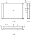
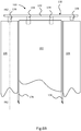
Figures 1A to 1C there is shown amodule 100 generally comprising aframe 102, afirst panel assembly 104 and asecond panel assembly 106 mounted on either side of theframe 102. Themodule 100 is generally rectangular and planar, and is shown inFigures 1A to 1C in a folded, flat configuration for storage and transportation in which the first andsecond panel assemblies frame 102. - Referring to
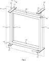
Figure 2 , theframe 102 is shown without thepanel assemblies frame 102 is a generally rectangular endless loop in shape, comprising horizontal top andbottom members vertical side members bottom members channels 116, thechannels 116 running longitudinally along themembers channels 116 can be used for routing e.g. electrical cables. A frame plane FP lies halfway through the thickness of theframe 102. - At the corners where the
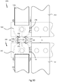
bottom member 110 and theside members fixed hinge plates hinge plates frame 102 on both sides. Eachhinge plate Figure 6A ). Thefirst hinge pin 123 is longer than thesecond hinge pin 124. Thehinge plates frame 102. Theplates frame 102 such that thefirst pin 123 of thefirst plate 120 is on the same side of theframe 102 as thesecond pin 124 of thesecond plate 122 and vice versa. - At the corners where the
top member 108 and theside members - The
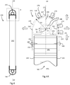
frame 102 further comprises a first and secondremovable hinge plate Figure 6A . Each comprises aplate member 132, with twocentral pins 134 or equal length extending therefrom. On a first side of thecentral pins 134 there is provided afirst hinge pin 136 which is shorter than the central pins 134. On a second side of thecentral pins 134 there is provided asecond hinge pin 138 which is shorter than thefirst hinge pin 136. - Turning to
Figures 3 ,4 and 4A , thefirst panel assembly 104 is shown. It will be understood that thesecond panel assembly 106 is identical to thefirst panel assembly 104. - The
first panel assembly 104 comprises arectangular panel core 140 having a panel plane PP halfway through its thickness. Thepanel core 140 is a thermally fused polypropylene panel having ahoneycomb polypropylene core 141 sandwiched between twoplanar sheets 143 of glass fibre reinforced polypropylene. Such panels are sold under the brand name MONOPAN (RTM) by Wihag Composites GmbH & Co. KG (although alternatives are available). These panels are strong, light, and have excellent thermal insulation properties. - At each vertical end of the
panel core 140 there are provided a first andsecond extrusion extrusions extrusion 142 is shown in detail inFigure 4A . Theextrusion 144 is identical to theextrusion 142. - The
extrusion 142 is prismatic. The section of theextrusion 142 comprises acentral cylinder 146 defining abore 148 having an axis X1 and an inner radius R1. A cross-member 150 extends tangentially either side of thecylinder 146. A first andsecond flange extrusion 142. Opposite the flanges, 152, 154, a hollowclosed section 158 extends from the cross-member 150 to contain thecylinder 146. Theclosed section 158 is defined by first and secondstraight walls flanges semi-circular wall section 164 having outer radius R2 and prescribing a 180 degree arc to join thewalls stiffener 166 extends radially from thecentral cylinder 146 to the inside of thesemi-circular wall section 164. - The geometric centre of the
semi-circular wall section 164, axis X2, is offset from axis X1 by offset distance OD. The axis X2 is offset towards thesemi-circular wall section 164, and away from theflanges - The
flanges extrusion 142 opposition the panel receiving formation is known as thefree end 172 which faces in a free end direction F. First and second sideward facing directions S1 and S2 are also defined inFigure 4A and are generally perpendicular to the directions P and F. - The
extrusion 142 defines two pairs of seal receiving formations in the form of outwardly facing slots. A first and secondseal receiving formation semi-circular wall section 164. Theseal receiving formations seal receiving formation seal receiving formation 174 is defined in the secondstraight wall 162, and the fourthseal receiving formation 176 is defined proximate the thirdseal receiving formation 174 in thesemi-circular wall section 164 where it joins the secondstraight wall 162. The third and fourth seal formations 174,176 face in the second sideways direction S2, substantially perpendicular to the first andsecond seal formations - Each of the
seal receiving formations formation 168 is shown in more detail inFigure 9F and comprises an undercutelongate slot 169 of width W1 arranged to receive a flange of a seal. Theseal receiving formation 168 defines amouth 171 in communication with theslot 169 having width W2 < W1. Theseals 178 are identical and are of the foam type, in this embodiment Q-LON (RTM) 69950 sold by Schlegel Systems, Inc. - Because the axis X2 of the
semi-circular wall section 164 is offset from the axis X1 of thebore 148, the first and secondseal receiving formations fourth seal formations - The modules are assembled as follows.
- The
first panel assembly 140 is assembled as follows. Theextrusions panel core 140. The end of the panel core is received within the panel receiving formation defined by theflanges panel core 140 andrespective extrusion screws 180. Theextrusions seal receiving formations seal receiving formations - The
seals 178 can be slid down the respective first pair ofseal receiving formations seal receiving formations - One both
panel assemblies frame 102. In the folded configuration, thefirst panel assembly 104 is mounted parallel to and adjacent the frame by placing therespective bores 148 in theextrusions hinge plates seal receiving formations frame 102. Similarly, thesecond panel assembly 106 is mounted to the hinge pins 123, 124 on the opposite side of theframe 102 with the third and fourth seal receiving formations facing the frame. - Once in position, the
removable hinge plates central pins 134 engaging thebores 126 in theframe 102. Thehinge plates first hinge pin 136 of the secondremovable hinge plate 132 is on the same side of the frame as thesecond hinge pin 138 of the firstremovable hinge plate 130 and vice versa. Also, the first hinge pins 136 of theremovable plates plates removable plates plates - Therefore for the
panel assembly 104, thefirst extrusion 142 is pivoted on a pair of second hinge pins 124, 138, and thesecond extrusion 144 is pivoted on a pair of first hinge pins 123, 136, in which the first hinge pins 123, 136 are shorter than the second hinge pins 123, 136. - Once the
removable hinge plates panel assemblies module 100 is formed in a folded or stowed position. - Referring to
Figure 5A , when thepanel assembly 106 is in the folded / stowed position, theseals 178 in the third and fourthseal receiving formations side member 114 of theframe 102 to provide and air- and water-tight seal. The use of two seals provides redundancy and improves the sealing capability of the arrangement. - Either or both of the panel assemblies 104,106 can be moved from the folded position to an extended position as shown in
Figure 7 . Starting with thefirst panel assembly 104, and referring toFigure 6B , the secondremovable hinge plate 130 can be lifted to free thesecond hinge pin 138 from thefirst panel assembly 104. Thepanel assembly 104 can then be lifted off thesecond hinge pin 124. Because the first hinge pins 123, 136 are longer than the second hinge pins 124, 138, the other end of the panel assembly is still captured, and can be rotated about a first panel axis PA1 as shown inFigure 7 . The same applies forpanel assembly 106, being selectively rotatable about a second panel axis PA2 at the opposite end and side of theframe 102 to the first panel axis PA1. - It will be understood that in addition to the foregoing articulation, the panel assemblies can also be completely removed if required by one of the applications described below.
- Referring to
Figures 8A to 8C , the movement of theextrusion 144 of thesecond panel assembly 106 during rotation about the second panel axis PA2, which coincides with the axis X1 of theextrusion 144. -
Figure 8A shows the clearance C between theextrusion 144 and theframe 102. Because of the offset distance OD between the axes X1 and X2, as thesecond panel assembly 106 rotates from the folded / stowed condition to the extended position perpendicular to theframe 102, the clearance C decreases by distance OD. This takes account of the fact that the seals (not shown) in the third and fourthseal receiving formations extrusion 144 than the seals in the first and secondseal receiving formations - Referring to
Figures 9A to 9E , various examples of modular buildings which can be constructed with themodule 100 are shown. -
Figure 9A shows abuilding 10 having a simple 1x1 module arrangement comprising themodule 100, and asecond module 100a, which is identical tomodule 100. Features ofmodule 100a equivalent tomodule 100 are denoted by the same reference numerals suffixed by a. - The
first panel assembly 104 of thefirst module 100 forms an end wall in the folded / stowed condition. Thesecond panel assembly 106 of thefirst module 100 has been rotated about its axis by 90 degrees to form a side wall. Thefirst panel assembly 104a of thesecond module 100a has been rotated about its axis by 90 degrees to form a side wall. Thesecond panel assembly 106a of thesecond module 100a remains in the folded / stowed condition to form an end wall. Thus the two modules have been combined with the end of thepanel assembly 106 of themodule 100 sealing against the side of theframe 102a of themodule 100a. Similarly, thepanel assembly 104a of themodule 100a seals against the side of theframe 102 of themodule 100. The joint at region E is shown in more detail inFigure 9E with theseals 178a of theextrusion 142a of thepanel assembly 104a abutting and sealing against theframe 102 of themodule 100. The first hinge pins 124, 138 retain theextrusion 142a of thepanel assembly 104a by engaging thebore 148a. -
Figure 9B shows asecond building 12 having a 2x1 arrangement comprising themodule 100, thesecond module 100a and athird module 100b which is identical tomodule 100. Features ofmodule 100b equivalent tomodule 100 are denoted by the same reference numerals suffixed by b. -
Module 100 is configured as per thebuilding 10, with thefirst panel assembly 104 stowed to form an end wall, and thesecond panel assembly 106 rotated through 90 degrees to form a sidewall sealing against theframe 102a of themodule 100a. - The
second module 100a has bothpanel assemblies first panel assembly 104a extends to seal against theframe 102a of thefirst module 100, and thesecond panel assembly 106a extends to seal against theframe 102b of thethird module 100b. - The
third module 100b is configured such that thefirst panel assembly 104b is rotated by 90 degrees to seal against theframe 102a of thesecond module 100a. Thesecond panel assembly 106b is kept in the folded / stowed position to form an end wall opposite and parallel to thefirst panel 104 of thefirst module 100. - Again, the joint at region E is shown in more detail in
Figure 9E . - Turning to
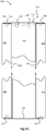
Figure 9C , a2x2 module building 14, the construction of which is made possible by the present invention, is shown in plan. The building comprises six modules, 100, 100a, 100b, 100c, 100d, 100e. Features of modules equivalent tomodule 100 are denoted by the same reference numerals suffixed by a, b, c etc. -
Modules building 12 with the exception that thesecond panel assemblies further modules - The
module 100c is configured such that theframe 102c is adjacent to and coplanar with theframe 102 of themodule 100. Thefirst panel assembly 104c is folded and as such is adjacent to and coplanar with thefirst panel assembly 104. Thesecond panel assembly 106c is rotated through 90 degrees to form a sidewall, and seals against theframe 102d of themodule 100d. - The
module 100d is provided with aframe 102d and asecond panel assembly 106d only. Theframe 102d is positioned adjacent to, and coplanar with, theframe 102a of themodule 100a. Thesecond panel assembly 106d is rotated through 90 degrees to seal against theframe 102e of themodule 100e. - The
module 100e is provided with aframe 102e and asecond panel assembly 106e only. Theframe 102e is in its folded / stowed condition to form an end wall adjacent to, and coplanar with, thesecond panel assembly 106c of themodule 100c. - The region D of
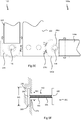
Figure 9C is shown in more detail inFigure 9D . There is a gap G between theframes panel assemblies - It will be noted that the first
seal receiving formation 168 of theextrusion 144 of thefirst panel assembly 104 of themodule 102 has a direct, uninterrupted line of sight to the firstseal receiving formation 168c of theextrusion 144c of thefirst panel assembly 104c of themodule 102c. In fact, theseal receiving formations - Similarly, the second
seal receiving formation 170 of theextrusion 144 of thefirst panel assembly 104 of themodule 102 has a direct, uninterrupted line of sight to the secondseal receiving formation 170c of theextrusion 144c of thefirst panel assembly 104c of themodule 102c. In fact, theseal receiving formations - A
first gap seal 182 is provided simultaneously engage with theseal receiving formations second gap seal 184 is provided simultaneously engage with theseal receiving formations Figure 9F . Thegap seal 182 defines a first andsecond flange seal body 190 which extends between, and normal to, theflanges flanges seal body 190 is flexible, having afoam core 191 andmembrane skin 193. Therefore the portions of the seal 182 (i.e. flanges 186, 188) which engages theseal receiving formations gap 171. - The fact that the seal pairs have a direct, uninterrupted line of sight to each other allows a simply unitary seal component (like
seals 182, 184) to bridge the gap simply and effectively. Further, because the seal receiving formations are undercut, theflanges extrusions 142, 144 (i.e. from the top or bottom of the walls). Theseals panel assemblies - The presence of two gap seals 182 (facilitated by two pairs of facing
seal receiving formations building 14. - In all
buildings - Variations of the above embodiments fall within the scope of the present invention.
- The seal receiving formations may be any kind of seal engaging formations capable of holding a seal in place. For example, although in the above embodiment the seal members are male and the seal receiving formations female, the seals may define a female formation to receive part of the panel assembly.
- Although the above embodiments provides separate extrusions defining panel-end features, it is envisaged that the panel assembly may instead be a unitary member constructed from e.g. additive layer manufacturing.
- The
modules 100 can be used to create NxM configuration buildings.
Claims (15)
- A modular building assembly comprising:a first module having a first module frame and a first module first side panel mounted on a side of the first module frame, the first module first side panel being moveable between a stowed position parallel to and adjacent the first module frame and a deployed position in which the first module first side panel projects from the first module frame, the first module first side panel defining an inter-panel seal engaging formation on at least one side;a second module having a second module frame and a second module first side panel mounted on a side of the second module frame, the second module first side panel being moveable between a stowed position parallel to and adjacent the second module frame and a deployed position in which the second module first side panel projects from the second module frame, the second module first side panel defining an inter-panel seal engaging formation on at least one side;an inter-panel seal having a first panel engaging formation and a second panel engaging formation;in which when the first and second modules are placed with their respective frames in an adjacent and co-planar relationship, the seal can be simultaneously engaged with the seal engaging members of each first side panel to seal the first and second modules together.
- A modular building assembly according to claim 1, in which the first module first side panel and the second module first side panel have an uninterrupted line of sight therebetween.
- A modular building assembly according to claim 2, in which the inter-panel seal engaging formation of the first module first side panel and the inter-panel seal engaging formation of the second module first side panel are configured to have an uninterrupted line of sight therebetween before the inter-panel seal is inserted.
- A modular building assembly according to any preceding claim, in which each first side panel defines an adjacent pair of inter-panel seal engaging formations, and in which two adjacent inter-panel seals are provided between each first side panel.
- A modular building assembly according to claim 4, in which each of the pair of inter-panel seal engaging formations is positioned either side of a central plane of the respective first side panel.
- A modular building assembly according to any preceding claim, in which each first side panel further defines a frame seal engaging formation facing the respective first or second module frame.
- A modular building assembly according to claim 6, in which the frame seal engaging formations face in a direction normal to the respective inter-panel seal engaging formations.
- A modular building assembly according to any preceding claim, in which each of the first and second module first side panels is pivotably mounted to the respective frame.
- A modular building assembly according to any preceding claim, in which:the first module has a first module second side panel mounted on a side of the first module frame opposite to the first module first side panel, the first module second side panel being moveable between a stowed position parallel to and adjacent the first module frame and a deployed position in which the first module second side panel projects from the first module frame; and,the second module has a second module second side panel mounted on a side of the second module frame opposite to the second module first side panel, the second module second side panel being moveable between a stowed position parallel to and adjacent the second module frame and a deployed position in which the second module second side panel projects from the second module frame.
- A modular building assembly according to claim 9, in which each first and second side panels is rotatable about a respective first and second panel axis, in which the first panel axis is at a first end of the frame, and the second panel axis is at a second end of the frame such that the respective frame and panels can form a "Z" shape.
- A modular building assembly according to any preceding claim, in which each of the side panels comprises a panel member and an edge member attached to opposite edges of the panel member, which edge members define the inter-panel seal engaging formation or formations.
- A modular building assembly according to claim 11, in which the edge members are extrusions defining the inter-panel seal engaging formation or formations parallel to an axis of extrusion.
- A modular building assembly according to claim 11 or 12, in which the edge members define one side of a rotational joint to facilitate rotation of the side panel from the stowed and deployed positions.
- A modular building assembly according to any preceding claim, in which the side panels comprise a cellular core with an outer skin preferably constructed from a thermally bonded polymer material.
- A method of constructing a modular building comprising the steps of:providing a first module having a first module frame and a first module first side panel mounted on a side of the first module frame, the first module first side panel being moveable between a stowed position parallel to and adjacent the first module frame and a deployed position in which the first module first side panel projects from the first module frame;providing a second module having a second module frame and a second module first side panel mounted on a side of the second module frame, the second module first side panel being moveable between a stowed position parallel to and adjacent the second module frame and a deployed position in which the second module first side panel projects from the second module frame;aligning the first and second module frames in an adjacent and co-planar relationship;providing an inter-panel seal;using the inter-panel seal to seal the first and second module first side panels together.
Applications Claiming Priority (1)
| Application Number | Priority Date | Filing Date | Title |
|---|---|---|---|
| GB1516513.7A GB2542390A (en) | 2015-09-17 | 2015-09-17 | Module assembly for a building |
Publications (1)
| Publication Number | Publication Date |
|---|---|
| EP3144437A1 true EP3144437A1 (en) | 2017-03-22 |
Family
ID=54544423
Family Applications (1)
| Application Number | Title | Priority Date | Filing Date |
|---|---|---|---|
| EP16189386.2A Withdrawn EP3144437A1 (en) | 2015-09-17 | 2016-09-19 | Module assembly for a building |
Country Status (2)
| Country | Link |
|---|---|
| EP (1) | EP3144437A1 (en) |
| GB (1) | GB2542390A (en) |
Families Citing this family (1)
| Publication number | Priority date | Publication date | Assignee | Title |
|---|---|---|---|---|
| CN116677079B (en) * | 2023-06-08 | 2024-03-12 | 重庆交通大学 | Assembled honeycomb building of quick construction |
Citations (4)
| Publication number | Priority date | Publication date | Assignee | Title |
|---|---|---|---|---|
| DE8013713U1 (en) * | 1979-05-23 | 1981-03-12 | Compagnie Internationale de Participation et d' Investissement CIPARI S.A., Luxembourg | Transportable company, commercial or storage building |
| GB2286337A (en) | 1994-02-09 | 1995-08-16 | David Charles Dyer | Improved means of collapsing and erecting structures |
| WO1997030257A1 (en) * | 1996-02-19 | 1997-08-21 | Innovation Development Enterprise I Stockholm Ab | Hinge |
| US5904005A (en) | 1995-02-18 | 1999-05-18 | Kudos 2000 Limited | Modular structures |
Family Cites Families (4)
| Publication number | Priority date | Publication date | Assignee | Title |
|---|---|---|---|---|
| FR2501754A1 (en) * | 1981-03-16 | 1982-09-17 | Sicopar | Modular element for lightweight building construction - is made up of unitary curved panels each with integral insulation and reinforced plastics seals |
| BE896466A (en) * | 1983-04-14 | 1983-08-01 | Applic De La Chemie De L Elect | DEVICE FOR SOLIDARIZING BETWEEN TWO CONTIGUOUS METAL CHASSIS BELONGING TO DIFFERENT LEVELS |
| US4965970A (en) * | 1988-01-19 | 1990-10-30 | Dynatherm Systems U.S.A. Ltd. | Prefabricated dome-shaped structure |
| JP3821949B2 (en) * | 1998-05-01 | 2006-09-13 | ヤマハリビングテック株式会社 | Wall panels |
-
2015
- 2015-09-17 GB GB1516513.7A patent/GB2542390A/en not_active Withdrawn
-
2016
- 2016-09-19 EP EP16189386.2A patent/EP3144437A1/en not_active Withdrawn
Patent Citations (4)
| Publication number | Priority date | Publication date | Assignee | Title |
|---|---|---|---|---|
| DE8013713U1 (en) * | 1979-05-23 | 1981-03-12 | Compagnie Internationale de Participation et d' Investissement CIPARI S.A., Luxembourg | Transportable company, commercial or storage building |
| GB2286337A (en) | 1994-02-09 | 1995-08-16 | David Charles Dyer | Improved means of collapsing and erecting structures |
| US5904005A (en) | 1995-02-18 | 1999-05-18 | Kudos 2000 Limited | Modular structures |
| WO1997030257A1 (en) * | 1996-02-19 | 1997-08-21 | Innovation Development Enterprise I Stockholm Ab | Hinge |
Also Published As
| Publication number | Publication date |
|---|---|
| GB201516513D0 (en) | 2015-11-04 |
| GB2542390A (en) | 2017-03-22 |
Similar Documents
| Publication | Publication Date | Title |
|---|---|---|
| US11566413B2 (en) | Enclosure members joined by hinged I-beam to fold flat | |
| US9988812B2 (en) | Interconnection system for panel assemblies | |
| US20190323535A1 (en) | Panels for an assembled product | |
| AU2002328693B2 (en) | Hollow interconnecting panels as lost formwork | |
| US20170233997A1 (en) | Expandable Panel | |
| EP3144437A1 (en) | Module assembly for a building | |
| CA3193275A1 (en) | Modular foldable building system and method | |
| US20150275945A1 (en) | Bidirectional modular assembly clip | |
| CN110537030B (en) | Panel for a composite product | |
| US5502938A (en) | Modular wall assembly system and elastic hinge therefor | |
| SE432275B (en) | CONSTRUCTION BUILDING SYSTEMS, SPECIFICALLY LIKELY CONSTRUCTIONS | |
| CN207988154U (en) | A kind of connection component of multi-layered modular building | |
| GB2480096A (en) | Temporary partitioning system comprising, in use, vertically elongate interlocking components | |
| US3760551A (en) | Structural assembly | |
| EP1483467B1 (en) | structural element | |
| US20130112356A1 (en) | Temporary Partition System and Components for the Same | |
| CA2865674C (en) | Interconnection system for panel assemblies | |
| CN216587010U (en) | Foldable assembled emergency room | |
| CN2730969Y (en) | Movable room assembly | |
| CN113216404B (en) | Container type shelter | |
| CN216239932U (en) | Folding combined type air tightness shelter | |
| KR101533778B1 (en) | Structure for assembling module unit for modular building | |
| JP3224732U (en) | Space partition panel unit | |
| GB2404207A (en) | Room divider panel | |
| CN113969674A (en) | Folding combined type air tightness shelter |
Legal Events
| Date | Code | Title | Description |
|---|---|---|---|
| PUAI | Public reference made under article 153(3) epc to a published international application that has entered the european phase |
Free format text: ORIGINAL CODE: 0009012 |
|
| AK | Designated contracting states |
Kind code of ref document: A1 Designated state(s): AL AT BE BG CH CY CZ DE DK EE ES FI FR GB GR HR HU IE IS IT LI LT LU LV MC MK MT NL NO PL PT RO RS SE SI SK SM TR |
|
| AX | Request for extension of the european patent |
Extension state: BA ME |
|
| STAA | Information on the status of an ep patent application or granted ep patent |
Free format text: STATUS: THE APPLICATION IS DEEMED TO BE WITHDRAWN |
|
| 18D | Application deemed to be withdrawn |
Effective date: 20170923 |