EP3144048A1 - Dispositif de purification des gaz d'échappement - Google Patents
Dispositif de purification des gaz d'échappement Download PDFInfo
- Publication number
- EP3144048A1 EP3144048A1 EP16188945.6A EP16188945A EP3144048A1 EP 3144048 A1 EP3144048 A1 EP 3144048A1 EP 16188945 A EP16188945 A EP 16188945A EP 3144048 A1 EP3144048 A1 EP 3144048A1
- Authority
- EP
- European Patent Office
- Prior art keywords
- face
- exhaust gas
- side end
- honeycomb
- catalyst body
- Prior art date
- Legal status (The legal status is an assumption and is not a legal conclusion. Google has not performed a legal analysis and makes no representation as to the accuracy of the status listed.)
- Pending
Links
- 239000003054 catalyst Substances 0.000 claims abstract description 177
- 239000000758 substrate Substances 0.000 claims abstract description 51
- 238000005192 partition Methods 0.000 claims description 67
- 238000000746 purification Methods 0.000 claims description 3
- 239000013618 particulate matter Substances 0.000 abstract description 40
- 238000002347 injection Methods 0.000 abstract description 19
- 239000007924 injection Substances 0.000 abstract description 19
- 239000007789 gas Substances 0.000 description 196
- MWUXSHHQAYIFBG-UHFFFAOYSA-N nitrogen oxide Inorganic materials O=[N] MWUXSHHQAYIFBG-UHFFFAOYSA-N 0.000 description 34
- 238000011156 evaluation Methods 0.000 description 24
- 239000000463 material Substances 0.000 description 17
- UGFAIRIUMAVXCW-UHFFFAOYSA-N Carbon monoxide Chemical compound [O+]#[C-] UGFAIRIUMAVXCW-UHFFFAOYSA-N 0.000 description 15
- 229910002091 carbon monoxide Inorganic materials 0.000 description 15
- 229930195733 hydrocarbon Natural products 0.000 description 15
- 150000002430 hydrocarbons Chemical class 0.000 description 15
- 239000002245 particle Substances 0.000 description 14
- 239000011148 porous material Substances 0.000 description 13
- 239000000446 fuel Substances 0.000 description 10
- 230000000052 comparative effect Effects 0.000 description 9
- 238000011144 upstream manufacturing Methods 0.000 description 8
- 230000003247 decreasing effect Effects 0.000 description 7
- 239000000969 carrier Substances 0.000 description 6
- 239000000919 ceramic Substances 0.000 description 6
- 230000007423 decrease Effects 0.000 description 5
- 230000000694 effects Effects 0.000 description 5
- 238000000034 method Methods 0.000 description 5
- 238000012360 testing method Methods 0.000 description 5
- CURLTUGMZLYLDI-UHFFFAOYSA-N Carbon dioxide Chemical compound O=C=O CURLTUGMZLYLDI-UHFFFAOYSA-N 0.000 description 4
- 238000006073 displacement reaction Methods 0.000 description 4
- QSHDDOUJBYECFT-UHFFFAOYSA-N mercury Chemical compound [Hg] QSHDDOUJBYECFT-UHFFFAOYSA-N 0.000 description 4
- 229910052753 mercury Inorganic materials 0.000 description 4
- KDLHZDBZIXYQEI-UHFFFAOYSA-N Palladium Chemical compound [Pd] KDLHZDBZIXYQEI-UHFFFAOYSA-N 0.000 description 3
- 238000006243 chemical reaction Methods 0.000 description 3
- 229910052878 cordierite Inorganic materials 0.000 description 3
- 238000011161 development Methods 0.000 description 3
- BASFCYQUMIYNBI-UHFFFAOYSA-N platinum Chemical compound [Pt] BASFCYQUMIYNBI-UHFFFAOYSA-N 0.000 description 3
- 239000002994 raw material Substances 0.000 description 3
- 230000001105 regulatory effect Effects 0.000 description 3
- 230000035939 shock Effects 0.000 description 3
- IJGRMHOSHXDMSA-UHFFFAOYSA-N Atomic nitrogen Chemical compound N#N IJGRMHOSHXDMSA-UHFFFAOYSA-N 0.000 description 2
- 229910002092 carbon dioxide Inorganic materials 0.000 description 2
- 239000001569 carbon dioxide Substances 0.000 description 2
- 230000003197 catalytic effect Effects 0.000 description 2
- 239000004568 cement Substances 0.000 description 2
- 229910010293 ceramic material Inorganic materials 0.000 description 2
- 239000002131 composite material Substances 0.000 description 2
- 230000008021 deposition Effects 0.000 description 2
- JSKIRARMQDRGJZ-UHFFFAOYSA-N dimagnesium dioxido-bis[(1-oxido-3-oxo-2,4,6,8,9-pentaoxa-1,3-disila-5,7-dialuminabicyclo[3.3.1]nonan-7-yl)oxy]silane Chemical compound [Mg++].[Mg++].[O-][Si]([O-])(O[Al]1O[Al]2O[Si](=O)O[Si]([O-])(O1)O2)O[Al]1O[Al]2O[Si](=O)O[Si]([O-])(O1)O2 JSKIRARMQDRGJZ-UHFFFAOYSA-N 0.000 description 2
- 230000006872 improvement Effects 0.000 description 2
- 239000007769 metal material Substances 0.000 description 2
- 238000000386 microscopy Methods 0.000 description 2
- 239000010948 rhodium Substances 0.000 description 2
- 229910010271 silicon carbide Inorganic materials 0.000 description 2
- 239000004071 soot Substances 0.000 description 2
- 229910000505 Al2TiO5 Inorganic materials 0.000 description 1
- LFQSCWFLJHTTHZ-UHFFFAOYSA-N Ethanol Chemical compound CCO LFQSCWFLJHTTHZ-UHFFFAOYSA-N 0.000 description 1
- XUIMIQQOPSSXEZ-UHFFFAOYSA-N Silicon Chemical compound [Si] XUIMIQQOPSSXEZ-UHFFFAOYSA-N 0.000 description 1
- JFBZPFYRPYOZCQ-UHFFFAOYSA-N [Li].[Al] Chemical compound [Li].[Al] JFBZPFYRPYOZCQ-UHFFFAOYSA-N 0.000 description 1
- 230000004913 activation Effects 0.000 description 1
- PNEYBMLMFCGWSK-UHFFFAOYSA-N aluminium oxide Inorganic materials [O-2].[O-2].[O-2].[Al+3].[Al+3] PNEYBMLMFCGWSK-UHFFFAOYSA-N 0.000 description 1
- 239000011230 binding agent Substances 0.000 description 1
- 230000033228 biological regulation Effects 0.000 description 1
- 230000015572 biosynthetic process Effects 0.000 description 1
- 230000008602 contraction Effects 0.000 description 1
- 230000007547 defect Effects 0.000 description 1
- 238000013461 design Methods 0.000 description 1
- KZHJGOXRZJKJNY-UHFFFAOYSA-N dioxosilane;oxo(oxoalumanyloxy)alumane Chemical compound O=[Si]=O.O=[Si]=O.O=[Al]O[Al]=O.O=[Al]O[Al]=O.O=[Al]O[Al]=O KZHJGOXRZJKJNY-UHFFFAOYSA-N 0.000 description 1
- 238000005516 engineering process Methods 0.000 description 1
- 230000007613 environmental effect Effects 0.000 description 1
- 238000010304 firing Methods 0.000 description 1
- 230000004907 flux Effects 0.000 description 1
- 239000011521 glass Substances 0.000 description 1
- 230000001771 impaired effect Effects 0.000 description 1
- 238000005259 measurement Methods 0.000 description 1
- 229910052751 metal Inorganic materials 0.000 description 1
- 239000002184 metal Substances 0.000 description 1
- 238000012986 modification Methods 0.000 description 1
- 230000004048 modification Effects 0.000 description 1
- 229910052863 mullite Inorganic materials 0.000 description 1
- 229910052757 nitrogen Inorganic materials 0.000 description 1
- 230000003647 oxidation Effects 0.000 description 1
- 238000007254 oxidation reaction Methods 0.000 description 1
- 229910052763 palladium Inorganic materials 0.000 description 1
- 230000035699 permeability Effects 0.000 description 1
- 229910052697 platinum Inorganic materials 0.000 description 1
- AABBHSMFGKYLKE-SNAWJCMRSA-N propan-2-yl (e)-but-2-enoate Chemical compound C\C=C\C(=O)OC(C)C AABBHSMFGKYLKE-SNAWJCMRSA-N 0.000 description 1
- 238000006722 reduction reaction Methods 0.000 description 1
- 230000000717 retained effect Effects 0.000 description 1
- 229910052703 rhodium Inorganic materials 0.000 description 1
- MHOVAHRLVXNVSD-UHFFFAOYSA-N rhodium atom Chemical compound [Rh] MHOVAHRLVXNVSD-UHFFFAOYSA-N 0.000 description 1
- 230000000630 rising effect Effects 0.000 description 1
- 239000011359 shock absorbing material Substances 0.000 description 1
- SBEQWOXEGHQIMW-UHFFFAOYSA-N silicon Chemical compound [Si].[Si] SBEQWOXEGHQIMW-UHFFFAOYSA-N 0.000 description 1
- 229910052710 silicon Inorganic materials 0.000 description 1
- 239000010703 silicon Substances 0.000 description 1
- HBMJWWWQQXIZIP-UHFFFAOYSA-N silicon carbide Chemical compound [Si+]#[C-] HBMJWWWQQXIZIP-UHFFFAOYSA-N 0.000 description 1
- 229910052596 spinel Inorganic materials 0.000 description 1
- 239000011029 spinel Substances 0.000 description 1
- 230000007480 spreading Effects 0.000 description 1
- 230000000087 stabilizing effect Effects 0.000 description 1
- 229910001220 stainless steel Inorganic materials 0.000 description 1
- 239000010935 stainless steel Substances 0.000 description 1
- XLYOFNOQVPJJNP-UHFFFAOYSA-N water Substances O XLYOFNOQVPJJNP-UHFFFAOYSA-N 0.000 description 1
- 229910001868 water Inorganic materials 0.000 description 1
Images


Classifications
-
- F—MECHANICAL ENGINEERING; LIGHTING; HEATING; WEAPONS; BLASTING
- F01—MACHINES OR ENGINES IN GENERAL; ENGINE PLANTS IN GENERAL; STEAM ENGINES
- F01N—GAS-FLOW SILENCERS OR EXHAUST APPARATUS FOR MACHINES OR ENGINES IN GENERAL; GAS-FLOW SILENCERS OR EXHAUST APPARATUS FOR INTERNAL COMBUSTION ENGINES
- F01N3/00—Exhaust or silencing apparatus having means for purifying, rendering innocuous, or otherwise treating exhaust
- F01N3/08—Exhaust or silencing apparatus having means for purifying, rendering innocuous, or otherwise treating exhaust for rendering innocuous
- F01N3/10—Exhaust or silencing apparatus having means for purifying, rendering innocuous, or otherwise treating exhaust for rendering innocuous by thermal or catalytic conversion of noxious components of exhaust
- F01N3/24—Exhaust or silencing apparatus having means for purifying, rendering innocuous, or otherwise treating exhaust for rendering innocuous by thermal or catalytic conversion of noxious components of exhaust characterised by constructional aspects of converting apparatus
- F01N3/28—Construction of catalytic reactors
- F01N3/2839—Arrangements for mounting catalyst support in housing, e.g. with means for compensating thermal expansion or vibration
- F01N3/2842—Arrangements for mounting catalyst support in housing, e.g. with means for compensating thermal expansion or vibration specially adapted for monolithic supports, e.g. of honeycomb type
-
- F—MECHANICAL ENGINEERING; LIGHTING; HEATING; WEAPONS; BLASTING
- F01—MACHINES OR ENGINES IN GENERAL; ENGINE PLANTS IN GENERAL; STEAM ENGINES
- F01N—GAS-FLOW SILENCERS OR EXHAUST APPARATUS FOR MACHINES OR ENGINES IN GENERAL; GAS-FLOW SILENCERS OR EXHAUST APPARATUS FOR INTERNAL COMBUSTION ENGINES
- F01N3/00—Exhaust or silencing apparatus having means for purifying, rendering innocuous, or otherwise treating exhaust
- F01N3/08—Exhaust or silencing apparatus having means for purifying, rendering innocuous, or otherwise treating exhaust for rendering innocuous
- F01N3/10—Exhaust or silencing apparatus having means for purifying, rendering innocuous, or otherwise treating exhaust for rendering innocuous by thermal or catalytic conversion of noxious components of exhaust
- F01N3/24—Exhaust or silencing apparatus having means for purifying, rendering innocuous, or otherwise treating exhaust for rendering innocuous by thermal or catalytic conversion of noxious components of exhaust characterised by constructional aspects of converting apparatus
- F01N3/28—Construction of catalytic reactors
- F01N3/2803—Construction of catalytic reactors characterised by structure, by material or by manufacturing of catalyst support
- F01N3/2825—Ceramics
- F01N3/2828—Ceramic multi-channel monoliths, e.g. honeycombs
-
- B—PERFORMING OPERATIONS; TRANSPORTING
- B01—PHYSICAL OR CHEMICAL PROCESSES OR APPARATUS IN GENERAL
- B01D—SEPARATION
- B01D46/00—Filters or filtering processes specially modified for separating dispersed particles from gases or vapours
- B01D46/24—Particle separators, e.g. dust precipitators, using rigid hollow filter bodies
- B01D46/2403—Particle separators, e.g. dust precipitators, using rigid hollow filter bodies characterised by the physical shape or structure of the filtering element
- B01D46/2418—Honeycomb filters
- B01D46/2422—Mounting of the body within a housing
-
- B—PERFORMING OPERATIONS; TRANSPORTING
- B01—PHYSICAL OR CHEMICAL PROCESSES OR APPARATUS IN GENERAL
- B01D—SEPARATION
- B01D46/00—Filters or filtering processes specially modified for separating dispersed particles from gases or vapours
- B01D46/24—Particle separators, e.g. dust precipitators, using rigid hollow filter bodies
- B01D46/2403—Particle separators, e.g. dust precipitators, using rigid hollow filter bodies characterised by the physical shape or structure of the filtering element
- B01D46/2418—Honeycomb filters
- B01D46/2425—Honeycomb filters characterized by parameters related to the physical properties of the honeycomb structure material
- B01D46/2429—Honeycomb filters characterized by parameters related to the physical properties of the honeycomb structure material of the honeycomb walls or cells
-
- B—PERFORMING OPERATIONS; TRANSPORTING
- B01—PHYSICAL OR CHEMICAL PROCESSES OR APPARATUS IN GENERAL
- B01D—SEPARATION
- B01D46/00—Filters or filtering processes specially modified for separating dispersed particles from gases or vapours
- B01D46/24—Particle separators, e.g. dust precipitators, using rigid hollow filter bodies
- B01D46/2403—Particle separators, e.g. dust precipitators, using rigid hollow filter bodies characterised by the physical shape or structure of the filtering element
- B01D46/2418—Honeycomb filters
- B01D46/2451—Honeycomb filters characterized by the geometrical structure, shape, pattern or configuration or parameters related to the geometry of the structure
- B01D46/2459—Honeycomb filters characterized by the geometrical structure, shape, pattern or configuration or parameters related to the geometry of the structure of the plugs
-
- B—PERFORMING OPERATIONS; TRANSPORTING
- B01—PHYSICAL OR CHEMICAL PROCESSES OR APPARATUS IN GENERAL
- B01D—SEPARATION
- B01D46/00—Filters or filtering processes specially modified for separating dispersed particles from gases or vapours
- B01D46/24—Particle separators, e.g. dust precipitators, using rigid hollow filter bodies
- B01D46/2403—Particle separators, e.g. dust precipitators, using rigid hollow filter bodies characterised by the physical shape or structure of the filtering element
- B01D46/2418—Honeycomb filters
- B01D46/2451—Honeycomb filters characterized by the geometrical structure, shape, pattern or configuration or parameters related to the geometry of the structure
- B01D46/247—Honeycomb filters characterized by the geometrical structure, shape, pattern or configuration or parameters related to the geometry of the structure of the cells
-
- B—PERFORMING OPERATIONS; TRANSPORTING
- B01—PHYSICAL OR CHEMICAL PROCESSES OR APPARATUS IN GENERAL
- B01D—SEPARATION
- B01D46/00—Filters or filtering processes specially modified for separating dispersed particles from gases or vapours
- B01D46/24—Particle separators, e.g. dust precipitators, using rigid hollow filter bodies
- B01D46/2403—Particle separators, e.g. dust precipitators, using rigid hollow filter bodies characterised by the physical shape or structure of the filtering element
- B01D46/2418—Honeycomb filters
- B01D46/2451—Honeycomb filters characterized by the geometrical structure, shape, pattern or configuration or parameters related to the geometry of the structure
- B01D46/2474—Honeycomb filters characterized by the geometrical structure, shape, pattern or configuration or parameters related to the geometry of the structure of the walls along the length of the honeycomb
-
- B—PERFORMING OPERATIONS; TRANSPORTING
- B01—PHYSICAL OR CHEMICAL PROCESSES OR APPARATUS IN GENERAL
- B01D—SEPARATION
- B01D46/00—Filters or filtering processes specially modified for separating dispersed particles from gases or vapours
- B01D46/24—Particle separators, e.g. dust precipitators, using rigid hollow filter bodies
- B01D46/2403—Particle separators, e.g. dust precipitators, using rigid hollow filter bodies characterised by the physical shape or structure of the filtering element
- B01D46/2418—Honeycomb filters
- B01D46/2451—Honeycomb filters characterized by the geometrical structure, shape, pattern or configuration or parameters related to the geometry of the structure
- B01D46/2476—Monolithic structures
-
- B—PERFORMING OPERATIONS; TRANSPORTING
- B01—PHYSICAL OR CHEMICAL PROCESSES OR APPARATUS IN GENERAL
- B01D—SEPARATION
- B01D46/00—Filters or filtering processes specially modified for separating dispersed particles from gases or vapours
- B01D46/24—Particle separators, e.g. dust precipitators, using rigid hollow filter bodies
- B01D46/2403—Particle separators, e.g. dust precipitators, using rigid hollow filter bodies characterised by the physical shape or structure of the filtering element
- B01D46/2418—Honeycomb filters
- B01D46/2451—Honeycomb filters characterized by the geometrical structure, shape, pattern or configuration or parameters related to the geometry of the structure
- B01D46/2478—Structures comprising honeycomb segments
-
- B—PERFORMING OPERATIONS; TRANSPORTING
- B01—PHYSICAL OR CHEMICAL PROCESSES OR APPARATUS IN GENERAL
- B01D—SEPARATION
- B01D46/00—Filters or filtering processes specially modified for separating dispersed particles from gases or vapours
- B01D46/24—Particle separators, e.g. dust precipitators, using rigid hollow filter bodies
- B01D46/2403—Particle separators, e.g. dust precipitators, using rigid hollow filter bodies characterised by the physical shape or structure of the filtering element
- B01D46/2418—Honeycomb filters
- B01D46/2451—Honeycomb filters characterized by the geometrical structure, shape, pattern or configuration or parameters related to the geometry of the structure
- B01D46/2482—Thickness, height, width, length or diameter
-
- B—PERFORMING OPERATIONS; TRANSPORTING
- B01—PHYSICAL OR CHEMICAL PROCESSES OR APPARATUS IN GENERAL
- B01D—SEPARATION
- B01D46/00—Filters or filtering processes specially modified for separating dispersed particles from gases or vapours
- B01D46/24—Particle separators, e.g. dust precipitators, using rigid hollow filter bodies
- B01D46/2403—Particle separators, e.g. dust precipitators, using rigid hollow filter bodies characterised by the physical shape or structure of the filtering element
- B01D46/2418—Honeycomb filters
- B01D46/2451—Honeycomb filters characterized by the geometrical structure, shape, pattern or configuration or parameters related to the geometry of the structure
- B01D46/2484—Cell density, area or aspect ratio
-
- B—PERFORMING OPERATIONS; TRANSPORTING
- B01—PHYSICAL OR CHEMICAL PROCESSES OR APPARATUS IN GENERAL
- B01D—SEPARATION
- B01D53/00—Separation of gases or vapours; Recovering vapours of volatile solvents from gases; Chemical or biological purification of waste gases, e.g. engine exhaust gases, smoke, fumes, flue gases, aerosols
- B01D53/34—Chemical or biological purification of waste gases
- B01D53/92—Chemical or biological purification of waste gases of engine exhaust gases
- B01D53/94—Chemical or biological purification of waste gases of engine exhaust gases by catalytic processes
- B01D53/944—Simultaneously removing carbon monoxide, hydrocarbons or carbon making use of oxidation catalysts
-
- B—PERFORMING OPERATIONS; TRANSPORTING
- B01—PHYSICAL OR CHEMICAL PROCESSES OR APPARATUS IN GENERAL
- B01D—SEPARATION
- B01D53/00—Separation of gases or vapours; Recovering vapours of volatile solvents from gases; Chemical or biological purification of waste gases, e.g. engine exhaust gases, smoke, fumes, flue gases, aerosols
- B01D53/34—Chemical or biological purification of waste gases
- B01D53/92—Chemical or biological purification of waste gases of engine exhaust gases
- B01D53/94—Chemical or biological purification of waste gases of engine exhaust gases by catalytic processes
- B01D53/9445—Simultaneously removing carbon monoxide, hydrocarbons or nitrogen oxides making use of three-way catalysts [TWC] or four-way-catalysts [FWC]
- B01D53/9454—Simultaneously removing carbon monoxide, hydrocarbons or nitrogen oxides making use of three-way catalysts [TWC] or four-way-catalysts [FWC] characterised by a specific device
-
- B—PERFORMING OPERATIONS; TRANSPORTING
- B01—PHYSICAL OR CHEMICAL PROCESSES OR APPARATUS IN GENERAL
- B01J—CHEMICAL OR PHYSICAL PROCESSES, e.g. CATALYSIS OR COLLOID CHEMISTRY; THEIR RELEVANT APPARATUS
- B01J35/00—Catalysts, in general, characterised by their form or physical properties
- B01J35/50—Catalysts, in general, characterised by their form or physical properties characterised by their shape or configuration
- B01J35/56—Foraminous structures having flow-through passages or channels, e.g. grids or three-dimensional monoliths
-
- F—MECHANICAL ENGINEERING; LIGHTING; HEATING; WEAPONS; BLASTING
- F01—MACHINES OR ENGINES IN GENERAL; ENGINE PLANTS IN GENERAL; STEAM ENGINES
- F01N—GAS-FLOW SILENCERS OR EXHAUST APPARATUS FOR MACHINES OR ENGINES IN GENERAL; GAS-FLOW SILENCERS OR EXHAUST APPARATUS FOR INTERNAL COMBUSTION ENGINES
- F01N13/00—Exhaust or silencing apparatus characterised by constructional features ; Exhaust or silencing apparatus, or parts thereof, having pertinent characteristics not provided for in, or of interest apart from, groups F01N1/00 - F01N5/00, F01N9/00, F01N11/00
- F01N13/009—Exhaust or silencing apparatus characterised by constructional features ; Exhaust or silencing apparatus, or parts thereof, having pertinent characteristics not provided for in, or of interest apart from, groups F01N1/00 - F01N5/00, F01N9/00, F01N11/00 having two or more separate purifying devices arranged in series
- F01N13/0097—Exhaust or silencing apparatus characterised by constructional features ; Exhaust or silencing apparatus, or parts thereof, having pertinent characteristics not provided for in, or of interest apart from, groups F01N1/00 - F01N5/00, F01N9/00, F01N11/00 having two or more separate purifying devices arranged in series the purifying devices are arranged in a single housing
-
- F—MECHANICAL ENGINEERING; LIGHTING; HEATING; WEAPONS; BLASTING
- F01—MACHINES OR ENGINES IN GENERAL; ENGINE PLANTS IN GENERAL; STEAM ENGINES
- F01N—GAS-FLOW SILENCERS OR EXHAUST APPARATUS FOR MACHINES OR ENGINES IN GENERAL; GAS-FLOW SILENCERS OR EXHAUST APPARATUS FOR INTERNAL COMBUSTION ENGINES
- F01N3/00—Exhaust or silencing apparatus having means for purifying, rendering innocuous, or otherwise treating exhaust
- F01N3/02—Exhaust or silencing apparatus having means for purifying, rendering innocuous, or otherwise treating exhaust for cooling, or for removing solid constituents of, exhaust
- F01N3/021—Exhaust or silencing apparatus having means for purifying, rendering innocuous, or otherwise treating exhaust for cooling, or for removing solid constituents of, exhaust by means of filters
- F01N3/022—Exhaust or silencing apparatus having means for purifying, rendering innocuous, or otherwise treating exhaust for cooling, or for removing solid constituents of, exhaust by means of filters characterised by specially adapted filtering structure, e.g. honeycomb, mesh or fibrous
- F01N3/0222—Exhaust or silencing apparatus having means for purifying, rendering innocuous, or otherwise treating exhaust for cooling, or for removing solid constituents of, exhaust by means of filters characterised by specially adapted filtering structure, e.g. honeycomb, mesh or fibrous the structure being monolithic, e.g. honeycombs
-
- F—MECHANICAL ENGINEERING; LIGHTING; HEATING; WEAPONS; BLASTING
- F01—MACHINES OR ENGINES IN GENERAL; ENGINE PLANTS IN GENERAL; STEAM ENGINES
- F01N—GAS-FLOW SILENCERS OR EXHAUST APPARATUS FOR MACHINES OR ENGINES IN GENERAL; GAS-FLOW SILENCERS OR EXHAUST APPARATUS FOR INTERNAL COMBUSTION ENGINES
- F01N3/00—Exhaust or silencing apparatus having means for purifying, rendering innocuous, or otherwise treating exhaust
- F01N3/02—Exhaust or silencing apparatus having means for purifying, rendering innocuous, or otherwise treating exhaust for cooling, or for removing solid constituents of, exhaust
- F01N3/021—Exhaust or silencing apparatus having means for purifying, rendering innocuous, or otherwise treating exhaust for cooling, or for removing solid constituents of, exhaust by means of filters
- F01N3/033—Exhaust or silencing apparatus having means for purifying, rendering innocuous, or otherwise treating exhaust for cooling, or for removing solid constituents of, exhaust by means of filters in combination with other devices
- F01N3/035—Exhaust or silencing apparatus having means for purifying, rendering innocuous, or otherwise treating exhaust for cooling, or for removing solid constituents of, exhaust by means of filters in combination with other devices with catalytic reactors, e.g. catalysed diesel particulate filters
-
- B—PERFORMING OPERATIONS; TRANSPORTING
- B01—PHYSICAL OR CHEMICAL PROCESSES OR APPARATUS IN GENERAL
- B01D—SEPARATION
- B01D2255/00—Catalysts
- B01D2255/90—Physical characteristics of catalysts
- B01D2255/915—Catalyst supported on particulate filters
-
- B—PERFORMING OPERATIONS; TRANSPORTING
- B01—PHYSICAL OR CHEMICAL PROCESSES OR APPARATUS IN GENERAL
- B01D—SEPARATION
- B01D2255/00—Catalysts
- B01D2255/90—Physical characteristics of catalysts
- B01D2255/92—Dimensions
- B01D2255/9202—Linear dimensions
-
- B—PERFORMING OPERATIONS; TRANSPORTING
- B01—PHYSICAL OR CHEMICAL PROCESSES OR APPARATUS IN GENERAL
- B01D—SEPARATION
- B01D2255/00—Catalysts
- B01D2255/90—Physical characteristics of catalysts
- B01D2255/92—Dimensions
- B01D2255/9205—Porosity
-
- B—PERFORMING OPERATIONS; TRANSPORTING
- B01—PHYSICAL OR CHEMICAL PROCESSES OR APPARATUS IN GENERAL
- B01D—SEPARATION
- B01D46/00—Filters or filtering processes specially modified for separating dispersed particles from gases or vapours
- B01D46/24—Particle separators, e.g. dust precipitators, using rigid hollow filter bodies
- B01D46/2403—Particle separators, e.g. dust precipitators, using rigid hollow filter bodies characterised by the physical shape or structure of the filtering element
- B01D46/2418—Honeycomb filters
- B01D46/2425—Honeycomb filters characterized by parameters related to the physical properties of the honeycomb structure material
- B01D46/24491—Porosity
-
- F—MECHANICAL ENGINEERING; LIGHTING; HEATING; WEAPONS; BLASTING
- F01—MACHINES OR ENGINES IN GENERAL; ENGINE PLANTS IN GENERAL; STEAM ENGINES
- F01N—GAS-FLOW SILENCERS OR EXHAUST APPARATUS FOR MACHINES OR ENGINES IN GENERAL; GAS-FLOW SILENCERS OR EXHAUST APPARATUS FOR INTERNAL COMBUSTION ENGINES
- F01N2240/00—Combination or association of two or more different exhaust treating devices, or of at least one such device with an auxiliary device, not covered by indexing codes F01N2230/00 or F01N2250/00, one of the devices being
- F01N2240/20—Combination or association of two or more different exhaust treating devices, or of at least one such device with an auxiliary device, not covered by indexing codes F01N2230/00 or F01N2250/00, one of the devices being a flow director or deflector
-
- F—MECHANICAL ENGINEERING; LIGHTING; HEATING; WEAPONS; BLASTING
- F01—MACHINES OR ENGINES IN GENERAL; ENGINE PLANTS IN GENERAL; STEAM ENGINES
- F01N—GAS-FLOW SILENCERS OR EXHAUST APPARATUS FOR MACHINES OR ENGINES IN GENERAL; GAS-FLOW SILENCERS OR EXHAUST APPARATUS FOR INTERNAL COMBUSTION ENGINES
- F01N2330/00—Structure of catalyst support or particle filter
- F01N2330/30—Honeycomb supports characterised by their structural details
- F01N2330/48—Honeycomb supports characterised by their structural details characterised by the number of flow passages, e.g. cell density
-
- F—MECHANICAL ENGINEERING; LIGHTING; HEATING; WEAPONS; BLASTING
- F01—MACHINES OR ENGINES IN GENERAL; ENGINE PLANTS IN GENERAL; STEAM ENGINES
- F01N—GAS-FLOW SILENCERS OR EXHAUST APPARATUS FOR MACHINES OR ENGINES IN GENERAL; GAS-FLOW SILENCERS OR EXHAUST APPARATUS FOR INTERNAL COMBUSTION ENGINES
- F01N2330/00—Structure of catalyst support or particle filter
- F01N2330/60—Discontinuous, uneven properties of filter material, e.g. different material thickness along the longitudinal direction; Higher filter capacity upstream than downstream in same housing
-
- F—MECHANICAL ENGINEERING; LIGHTING; HEATING; WEAPONS; BLASTING
- F01—MACHINES OR ENGINES IN GENERAL; ENGINE PLANTS IN GENERAL; STEAM ENGINES
- F01N—GAS-FLOW SILENCERS OR EXHAUST APPARATUS FOR MACHINES OR ENGINES IN GENERAL; GAS-FLOW SILENCERS OR EXHAUST APPARATUS FOR INTERNAL COMBUSTION ENGINES
- F01N2340/00—Dimensional characteristics of the exhaust system, e.g. length, diameter or volume of the apparatus; Spatial arrangements of exhaust apparatuses
- F01N2340/02—Dimensional characteristics of the exhaust system, e.g. length, diameter or volume of the apparatus; Spatial arrangements of exhaust apparatuses characterised by the distance of the apparatus to the engine, or the distance between two exhaust treating apparatuses
-
- F—MECHANICAL ENGINEERING; LIGHTING; HEATING; WEAPONS; BLASTING
- F01—MACHINES OR ENGINES IN GENERAL; ENGINE PLANTS IN GENERAL; STEAM ENGINES
- F01N—GAS-FLOW SILENCERS OR EXHAUST APPARATUS FOR MACHINES OR ENGINES IN GENERAL; GAS-FLOW SILENCERS OR EXHAUST APPARATUS FOR INTERNAL COMBUSTION ENGINES
- F01N2470/00—Structure or shape of gas passages, pipes or tubes
- F01N2470/02—Tubes being perforated
-
- Y—GENERAL TAGGING OF NEW TECHNOLOGICAL DEVELOPMENTS; GENERAL TAGGING OF CROSS-SECTIONAL TECHNOLOGIES SPANNING OVER SEVERAL SECTIONS OF THE IPC; TECHNICAL SUBJECTS COVERED BY FORMER USPC CROSS-REFERENCE ART COLLECTIONS [XRACs] AND DIGESTS
- Y02—TECHNOLOGIES OR APPLICATIONS FOR MITIGATION OR ADAPTATION AGAINST CLIMATE CHANGE
- Y02T—CLIMATE CHANGE MITIGATION TECHNOLOGIES RELATED TO TRANSPORTATION
- Y02T10/00—Road transport of goods or passengers
- Y02T10/10—Internal combustion engine [ICE] based vehicles
- Y02T10/12—Improving ICE efficiencies
Definitions
- the present invention relates to an exhaust gas purifying device, and more particularly, it relates to an exhaust gas purifying device which is capable of efficiently removing particulates in an exhaust gas emitted from a direct injection type gasoline engine and efficiently purifying the exhaust gas.
- a suction port fuel injection type is mainly employed.
- this suction port fuel injection type it is possible to suppress an amount of a particulate matter (PM) such as soot to be generated, and influences of the particulate matter on atmospheric pollution or natural environment are not especially large.
- PM particulate matter
- this gasoline engine is poor in fuel economy performance as compared with the direct injection type gasoline engine.
- the decrease of the fuel consumption can be promoted as compared with the usual gasoline engine.
- the amount of the particulate matter to be generated is excessively larger than before, and it is necessary to emit the exhaust gas including the generated particulate matter to atmospheric air through an appropriate treatment. That is, the treatment of the particulate matter becomes complicated, and a device or equipment concerned with the treatment is required.
- a trapping filter in which a honeycomb structure is used is attached to the diesel engine for the purpose of removing a particulate matter in an exhaust gas which is generated by an operation of the diesel engine.
- a honeycomb structure for use in the exhaust gas purifying device there is mainly used a plugged honeycomb structure (see Patent Document 1) including plugging portions with which both ends are plugged in accordance with a predetermined arrangement standard.
- the exhaust gas emitted from the diesel engine flows into the above plugged honeycomb structure, and passes through partition walls of the plugged honeycomb structure which are made of a porous ceramic material, whereby the particulate matter is trapped by the partition walls and deposited thereon.
- the particulate matter in the exhaust gas emitted from the diesel engine can be removed by the trapping filter, and the gas passed through the trapping filter can be converted to a purified gas.
- fuel for use in the diesel engine is different from that in the gasoline engine, and hence even when the above trapping filter for the diesel engine is used as it is in the gasoline engine, the particulate matter cannot efficiently be removed.
- an exhaust gas emitted from a direct injection type gasoline engine can efficiently be purified and treated by utilizing a trapping filter in which a honeycomb structure is used.
- a honeycomb catalyst body onto which a three-way catalyst is loaded is further disposed at a position on an upstream side of a plugged honeycomb structure in which parts of cells are plugged, and for the purpose of decreasing a heat capacity of the honeycomb catalyst body, there is used a thin plate-shaped honeycomb catalyst body in which a length in a cell central axis direction is shorter than that of the plugged honeycomb structure.
- the exhaust gas purifying device In the exhaust gas purifying device, a larger amount of the exhaust gas flows through an end face central region corresponding to a region in the vicinity of an end face center (middle) in the honeycomb catalyst body and the plugged honeycomb structure, and the exhaust gas hardly flows through an end face circumferential region positioned around the end face central region. That is, in the exhaust gas purifying device, unevenness occurs in the flow of the exhaust gas. For example, in the vicinity of the end face central region in which a large amount of exhaust gas flows, a large amount of a particulate matter is trapped, and in the other region (the end face circumferential region), the particulate matter is hardly trapped. In this way, large unevenness occurs in the trapping regions of the particulate matter.
- the particulate matter is easily deposited on partition walls of cells of the end face central region, and by a purifying treatment of the particulate matter over a long period of time, there might be caused a defect that the cells of the end face central region are clogged. Furthermore, due to the deposition of the particulate matter, a pressure loss might increase. Therefore, there might occur the problem that a purifying efficiency and a purifying performance of the particulate matter in the exhaust gas purifying device remarkably deteriorate.
- the exhaust gas hardly flows similarly in the end face circumferential region positioned around the end face central region. Consequently, in an effective cross section of the honeycomb catalyst body, there occurs the problem that the exhaust gas is not efficiently purified.
- the present invention has been developed in view of the above actual circumstances, and an object thereof is to provide an exhaust gas purifying device in which an exhaust gas emitted from a direct injection type gasoline engine evenly flows into end faces of a plugged honeycomb structure and a honeycomb catalyst body and which is capable of stabilizing a purifying efficiency of a particulate matter and efficiently purifying the exhaust gas.
- an exhaust gas purifying device in which the above objects are achieved.
- an exhaust gas purifying device of the present invention there can be varied pressure losses due to an exhaust gas in an end face central region and/or an end face circumferential region in a second inflow side end face and a second outflow side end face of a second honeycomb substrate disposed in a plugged honeycomb structure, respectively.
- the pressure loss in the vicinity of the end face central region can be larger than the pressure loss of the end face circumferential region
- the exhaust gas can be inhibited from unevenly flowing into an end face central region of a honeycomb catalyst body and the end face central region of the plugged honeycomb structure, and the exhaust gas can uniformly flow through a first inflow side end face and/or a first outflow side end face and the second inflow side end face and/or the second outflow side end face.
- exhaust gas purifying device of the present invention is not limited to the following embodiment, and various design changes, modifications, improvements and the like can be added without departing from the gist of the present invention.
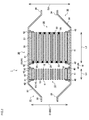
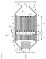
- an exhaust gas purifying device 1 of the present embodiment mainly includes a honeycomb catalyst body 10 including a first honeycomb substrate 15 having latticed partition walls 14 defining a plurality of cells 13 extending from a first inflow side end face 11 to a first outflow side end face 12, and a catalyst loaded onto the first honeycomb substrate 15, both ends of the cells 13 being opened, respectively; a plugged honeycomb structure 20 including a second honeycomb substrate 25 having latticed partition walls 24 defining a plurality of cells 23 extending from a second inflow side end face 21 to a second outflow side end face 22, and a plurality of plugging portions 26 arranged to plug open ends of the cells 23 in the second inflow side end face 21 and/or the second outflow side end face 22 in accordance with a predetermined arrangement standard; and a can member 30 which is made of a metal and formed to receive the honeycomb catalyst body 10 and the plugged honeycomb structure 20, and includes an exhaust gas inflow portion 31 and
- the honeycomb catalyst body 10 is received in the can member 30 so that the first inflow side end face 11 of the first honeycomb substrate 15 faces an inflow port 33 of the exhaust gas inflow portion 31 of the can member 30, whereas the plugged honeycomb structure 20 is received in the can member 30 so that the second outflow side end face 22 faces an emitting port 34 of the purified gas emitting portion 32 of the can member 30. That is, the honeycomb catalyst body 10 is positioned on an upstream side in the can member 30, and the plugged honeycomb structure 20 is positioned at a position on a downstream side of the honeycomb catalyst body (see Fig. 1 and Fig. 2 ).
- the honeycomb catalyst body 10 and the plugged honeycomb structure 20 received in the can member 30 are positioned so that the first outflow side end face 12 of the honeycomb catalyst body 10 (the first honeycomb substrate 15) faces the second inflow side end face 21 of the plugged honeycomb structure 20 (the second honeycomb substrate 25), and furthermore, a predetermined clearance (a distance W) is disposed between the first outflow side end face 12 and the second inflow side end face 21.
- a predetermined clearance disposed between the first outflow side end face 12 and the second inflow side end face 21. It is to be noted that the distance W between the first outflow side end face 12 and the second inflow side end face 21 is set to a range of 1 to 20 mm in the present embodiment.
- the can member 30 is mainly made of a metal material, and constituted to have a structure and an inner diameter in which the round pillar-shaped honeycomb catalyst body 10 and plugged honeycomb structure 20 can be received and stored, respectively, and the can member includes a cylindrical can member the main body 35 having an inner diameter D3 which is larger than a diameter D1 of the honeycomb catalyst body 10 and a diameter D2 of the plugged honeycomb structure 20, and the exhaust gas inflow portion 31 and the purified gas emitting portion 32 which are attached to both ends of the can member main body 35, respectively.
- the exhaust gas inflow portion 31 is connected to an exhaust gas emitting section (not shown) of a direct injection type gasoline engine to introduce an exhaust gas EG to the exhaust gas purifying device 1, and the exhaust gas inflow portion includes an introduction pipe 36 constituted of a cylindrical member having a diameter which is smaller than that of the can member main body 35, and a truncated conical diameter expanding portion 37 having a diameter which increases from the inflow port 33 at one end of the introduction pipe 36 to the can member main body 35.
- the purified gas emitting portion 32 emits, to the outside, a purified gas CG which is cleaned while passing through the plugged honeycomb structure 20, and the purified gas emitting portion includes a truncated conical diameter reducing portion 38 having a diameter which decreases from the other end of the can member main body 35, and a small-diameter cylindrical emission tube 39 connected to the emitting port 34 at one end of the diameter reducing portion 38 to emit the purified gas CG to the outside.
- the introduction pipe 36 and the emission tube 39 have the same shape, and the diameter expanding portion 37 and the diameter reducing portion 38 have the same shape.
- the honeycomb catalyst body 10 is disposed at the upstream position of the plugged honeycomb structure 20 in the can member 30, so that the inflow port 33 of the exhaust gas inflow portion 31 can face the first inflow side end face 11 of the honeycomb catalyst body 10.
- a temperature of the honeycomb catalyst body 10 can be raised by utilizing the heat of the high-temperature exhaust gas EG sent from the direct injection type gasoline engine, and the temperature can reach a temperature at which the loaded catalyst indicates a high activity, in a short time.
- a purifying treatment of the exhaust gas EG can efficiently be performed by utilizing the high catalytic activity immediately after the start of the engine.
- the inner diameter D3 of the cylindrical can member the main body 35 of the can member 30 is designed to be larger than each of the diameters D1 and D2 of the honeycomb catalyst body 10 and the plugged honeycomb structure 20. Therefore, in a case where the honeycomb catalyst body 10 and the like are received as they are in the can member 30, a clearance is generated between an inner circumferential wall surface 40 of the can member main body 35 and each of an outer circumferential wall surface 16 of the honeycomb catalyst body 10 and an outer circumferential wall surface 27 of the plugged honeycomb structure 20, the honeycomb catalyst body 10 and the like are movable in the can member 30, and hence a stored state is not stable.
- a cushion material 41 made of a shock-absorbing material is interposed between the outer circumferential wall surface 16 or the like of the honeycomb catalyst body 10 or the like and the inner circumferential wall surface 40 of the can member main body 35.
- the above clearance is filled with the cushion material 41, so that the movement of the honeycomb catalyst body 10 or the like in the can member main body 35 can be regulated and the stored state can be stabilized.
- a pair of stopper members 42 having an L-shaped cross section are attached along the inner circumferential wall surface 40.
- the movement of the honeycomb catalyst body 10 or the like in the forward-backward direction in the can member 30 is regulated by the pair of stopper members 42 which are fixed to abut on the first inflow side end face 11 and the first outflow side end face 12 of the honeycomb catalyst body 10 and the second inflow side end face 21 and the second outflow side end face 22 of the plugged honeycomb structure 20, respectively, and to sandwich the honeycomb catalyst body 10 and the plugged honeycomb structure 20 between the stopper members.
- the honeycomb catalyst body 10 and the plugged honeycomb structure 20 can stably be stored in the can member main body 35. Furthermore, even in a case where shock is given to the can member 30, the shock can be absorbed by the cushion material 41 and the like, and possibilities that cracks, chips and the like are generated in the honeycomb catalyst body 10 and the like can be decreased.
- the honeycomb catalyst body 10 for use in the exhaust gas purifying device 1 of the present embodiment possesses a round pillar-shaped structure, and has the quadrangularly latticed partition walls 14 defining the plurality of cells 13 extending from the first inflow side end face 11 to the first outflow side end face 12.
- the honeycomb catalyst body 10 for use in the exhaust gas purifying device 1 of the present embodiment possesses a round pillar-shaped structure, and has the quadrangularly latticed partition walls 14 defining the plurality of cells 13 extending from the first inflow side end face 11 to the first outflow side end face 12.
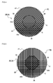
- the plugged honeycomb structure 20 for use in the exhaust gas purifying device 1 possesses a round pillar-shaped structure, has the quadrangularly latticed partition walls 24 defining the plurality of cells 23 extending from the second inflow side end face 21 to the second outflow side end face 22, and is designed so that a pressure loss of an end face central region C (corresponding to the inside of a broken-line circle of each of Fig. 4 and Fig. 5 ) in the second inflow side end face 21 and the second outflow side end face 22 becomes larger than a pressure loss of an end face circumferential region O (corresponding to the outside of the broken-line circle of each of Fig. 4 and Fig. 5 ) positioned around the end face central region C.
- the plugging portions 26 to plug open ends of predetermined cells 23a opened in the second inflow side end face 21 and open ends of the residual cells 23b of the second outflow side end face 22, respectively, are arranged regularly in accordance with a predetermined arrangement standard (see Fig. 4, Fig. 5 , etc.).
- the predetermined cells 23a of the end face central region C are alternately plugged, and further in a lower stage, the cells are shifted one by one and alternately plugged, whereby the plurality of plugging portions 26 are arranged in the form of a lattice to possess a checkerboard pattern.
- the cells are alternately plugged and in a lower stage, the cells are shifted one by one and alternately plugged, whereby the plurality of plugging portions 26 are arranged in the form of the lattice in the same manner as in the end face central region C of the second inflow side end face 21 (see Fig. 4 ).
- any plugging portions 26 are not arranged (see Fig. 5 ). That is, all the cells 23b in the second outflow side end face 22 of the end face circumferential region O are opened.
- the plugging portions 26 are arranged in the second inflow side end face 21 and the second outflow side end face 22 of the end face central region C, whereas the plugging portions 26 are arranged only in the second inflow side end face 21 of the end face circumferential region O.
- the pressure loss of the end face circumferential region O is smaller than that of the end face central region C, and the exhaust gas EG easily flows into the end face circumferential region.
- the arrangement standard of the plugging portions 26 is changed between the second inflow side end face 21 and the second outflow side end face 22, thereby differentiating open frontal areas of the cells 23 in the end face central region C and the end face circumferential region O, and the flow of the exhaust gas EG can optionally be controlled, so that the exhaust gas EG can be inhibited from unevenly flowing only in the end face central region C.
- open frontal areas of each cells 23 in the end face central region C and the end face circumferential region O may be differentiated by employing HAC structure (details are described later) on open shapes of cells for example. Thereby a difference in pressure loss is made between the end face central region C and the end face circumferential region O.
- the end face central region C includes at least a region in which the inflow port 33 of the can member 30 is vertically projected as it is on the second inflow side end face 21 (or the second outflow side end face 22), and a central region area (corresponding to an area in the broken-line circle of each of Fig. 4 and Fig. 5 ) of the end face central region C is set to a size equal to an inflow port sectional area in the inflow port 33 of the exhaust gas inflow portion 31 which faces the second inflow side end face 21 via the honeycomb catalyst body 10, or larger than the inflow port sectional area.
- the exhaust gas EG flowing from the exhaust gas inflow portion 31 into the can member 30 generally indicates straight advancing properties. Therefore, in a conventional exhaust gas purifying device, the exhaust gas EG reaching the diameter expanding portion 37 from the inflow port 33 advances as it is a bore of the inflow port 33, and is to straightly reach the first inflow side end face 11 of the honeycomb catalyst body 10 without enlarging in an upward-downward direction (corresponding to the upward-downward direction of the paper surface in Fig. 2 ) and the right-left direction (corresponding to a proximal-distal direction of the paper surface in Fig. 2 ).
- the exhaust gas EG which has received a catalyst active reaction by the honeycomb catalyst body 10 reaches the second inflow side end face 21 of the plugged honeycomb structure 20 through the above-mentioned clearance (the distance W) from the first outflow side end face 12. Also at this time, the exhaust gas EG indicates the straight advancing properties while flowing, and hence a large amount of exhaust gas EG is to flow into the second inflow side end face 21 in the vicinity of the end face central region C of the plugged honeycomb structure 20.
- the pressure loss of the end face central region C of the plugged honeycomb structure 20 is adjusted to be larger than that of the end face circumferential region O, so that the flow of the exhaust gas EG which is to advance straightly from the inflow port 33 can be regulated to direct a part of the exhaust gas EG toward the end face circumferential region O around the end face central region C. That is, in a case where a difference in pressure loss is made between the end face central region C and the end face circumferential region O in the can member 30, the exhaust gas EG flows toward the end face circumferential region O in which the pressure loss is small.
- the material constituting the plugging portions 26 to be arranged in the plugged honeycomb structure 20 can be made of a plugging material in which a ceramic raw material, alcohol, an organic binder and the like are combined, and it is preferable that the ceramic raw material is the same or the same type as a ceramic raw material of the first honeycomb substrate 15 or the second honeycomb substrate 25 which will be described later. Consequently, a behavior at a high temperature during firing can be identical, and the partition walls 24 and the plugging portions 26 can firmly be bonded without overloading each space between the partition walls 24 and the plugging portions 26 due to thermal expansion or thermal contraction.
- the honeycomb catalyst body 10 for use in the exhaust gas purifying device 1 of the present embodiment includes the first honeycomb substrate 15 which possesses a round pillar-shaped structure and has the latticed partition walls 14 made of a porous material and defining the plurality of cells 13 extending from the first inflow side end face 11 to the first outflow side end face 12, and both ends of each cell 13 are not closed with the plurality of plugging portions 26 as in the plugged honeycomb structure 20, i.e., one of the end faces 11 and 12 of the cell is opened.
- This ratio is further preferably in a range of 0.15 to 0.35 and especially preferably in a range of 0.2 to 0.3.
- a porosity of the partition walls 14 of the first honeycomb substrate 15 of the honeycomb catalyst body 10 is set to be smaller than a porosity of the partition walls 24 of the second honeycomb substrate 25 of the plugged honeycomb structure 20.
- an amount of the catalyst to be loaded per unit volume onto the partition walls 14 of the honeycomb catalyst body 10 can be adjusted in a range of 200 to 400 g/L. It is to be noted that the catalyst may be loaded or does not have to be loaded onto the partition walls 24 of the plugged honeycomb structure 20. At this time, it is necessary to adjust the amount of the catalyst to be loaded onto the partition walls 24 of the plugged honeycomb structure 20 in a range of 10 to 120 g/L so that the amount is smaller than the amount of the catalyst to be loaded per unit volume onto the partition walls 14 of the honeycomb catalyst body 10. The amount of the catalyst to be loaded is suppressed to such a degree, so that influences of the pressure loss due to the catalyst in the plugged honeycomb structure 20 can be decreased.
- the amount of the catalyst to be loaded per unit volume onto the honeycomb catalyst body 10 is preferably set to a range of 200 to 400 g/L, further preferably set to a range of 200 to 300 g/L, and especially preferably set to a range of 200 to 250 g/L as described above.
- the amount of the catalyst to be loaded is smaller than 200 g/L, the amount of the catalyst to be loaded onto the partition walls 14 runs short, and hence there is the possibility that generation of a quantity of the heat which is caused by the catalyst active reaction is inhibited and that more time is required to raise the temperature of the honeycomb catalyst body to the temperature at which the catalyst indicates the activity. Therefore, it becomes difficult to efficiently purify the exhaust gas EG immediately after the start of the engine.
- the amount of the loaded catalyst is in excess of 400 g/L, there is the fear that the through channels of the cells 13 become narrower, and there is the fear that the pressure loss heightens in the whole honeycomb catalyst body 10.
- the amount of the catalyst to be loaded is adjusted in the above range.
- Fig. 3 is a plan view showing the first inflow side end face 11 of the honeycomb catalyst body 10 for use in the exhaust gas purifying device 1.
- an appearance shape of the honeycomb catalyst body 10 is not limited to the above round pillar shape, and the shape may be, for example, an elliptic pillar shape, a quadrangular pillar shape or the like.
- a partition wall thickness of the partition walls 14 of the first honeycomb substrate 15 of the honeycomb catalyst body 10 is preferably in a range of 50.8 to 101.6 ⁇ m, further preferably in a range of 50.8 to 75 ⁇ m, and especially preferably in a range of 65 to 75 ⁇ m.
- the thickness is smaller than 50.8 ⁇ m, there is the fear that strength of the honeycomb catalyst body 10 deteriorates.
- the thickness is in excess of 101.6 ⁇ m, there is a high possibility that the pressure loss increases when the exhaust gas EG passes through the cells 13.
- the partition wall thickness is a value measured by microscopy of a cross section of the honeycomb catalyst body which is parallel to the central axis direction.
- the porosity of the partition walls 14 of the first honeycomb substrate 15 of the honeycomb catalyst body 10 is set to be smaller than the porosity of the partition walls 24 of the second honeycomb substrate 25 of the plugged honeycomb structure 20. Consequently, the strength of the honeycomb catalyst body 10 can be secured.
- a heat capacity of the honeycomb catalyst body 10 becomes smaller than a heat capacity of the plugged honeycomb structure 20, and hence a temperature rising rate of the honeycomb catalyst body 10 is faster than that of the plugged honeycomb structure 20.
- the porosity of the partition walls 14 is preferably adjusted to be smaller than the porosity of the partition walls 24. Furthermore, the temperature of the honeycomb catalyst body 10 is rapidly raised, and hence the temperature of the honeycomb catalyst body 10 can be raised by utilizing the heat of the exhaust gas EG. Consequently, the temperature of the plugged honeycomb structure 20 can rapidly be raised.
- the porosity of the partition walls 14 is not any special restriction on the porosity of the partition walls 14, but, for example, the porosity is preferably in a range of 20 to 50%, further preferably in a range of 25 to 38%, and especially preferably in a range of 25 to 30%. In a case where the porosity is smaller than 20%, there is the fear that the pressure loss increases, and in a case where the porosity is in excess of 50%, the honeycomb catalyst body 10 becomes brittle and easily falls. It is to be noted that the porosity of the partition walls 14 is a value measured by a mercury porosimeter.
- an average pore diameter of the partition walls 14 is preferably in a range of 5 to 30 ⁇ m and further preferably in a range of 10 to 25 ⁇ m.
- the average pore diameter of the partition walls 14 is smaller than 5 ⁇ m, close contact properties between the catalyst and the surfaces of the partition walls 14 cannot sufficiently be obtained, and there is the fear that a catalyst layer peels.
- the average pore diameter is in excess of 30 ⁇ m, the honeycomb catalyst body 10 becomes brittle and easily falls.
- the average pore diameter of the partition walls 14 is a value measured by the mercury porosimeter in the same manner as in the porosity.
- the first honeycomb substrate 15 constituting the honeycomb catalyst body 10 includes ceramic as a main component.
- An example of a material of the partition walls 14 is preferably at least one selected from the group consisting of silicon carbide, a silicon-silicon carbide based composite material, cordierite, mullite, alumina, spinel, a silicon carbide-cordierite based composite material, lithium aluminum silicate and aluminum titanate.
- cordierite which has a small thermal expansion coefficient and is excellent in thermal shock resistance, is especially preferably used to constitute the first honeycomb substrate 15.
- the honeycomb catalyst body may have a circumferential wall in its outermost circumference.
- the circumferential wall is especially preferably a formed monolithic wall which is formed integrally with a porous substrate during formation, but the circumferential wall may be constructed by using a ceramic cement material or the like after grinding a circumference of the porous substrate.
- the circumferential wall is preferably made of the same material as in the honeycomb catalyst body 10.
- the circumferential wall is constructed by using the ceramic cement material, there may be used a material obtained by adding a flux component of glass or the like to a common base material.
- the three-way catalyst is a catalyst to mainly purify hydrocarbons (HC), carbon monoxide (CO) and nitrogen oxides (NO x ), and the three-way catalyst may include, for example, platinum (Pt), palladium (Pd) and rhodium (Rh).
- hydrocarbons are purified into water and carbon dioxide
- carbon monoxide is purified into carbon dioxide
- nitrogen oxides are purified into nitrogen, respectively, by oxidation or reduction reaction.
- Fig. 4 and Fig. 5 are plan views showing the second inflow side end face 21 ( Fig. 4 ) and the second outflow side end face 22 ( Fig. 5 ) of the plugged honeycomb structure 20 for use in the exhaust gas purifying device 1.
- the plugged honeycomb structure 20 possesses a round pillar-shaped structure.
- An example of a size of the plugged honeycomb structure 20 is the length L2 of 50 to 200 mm in the central axis direction.
- the diameter D2 of the plugged honeycomb structure 20 is preferably from 80 to 180 mm.
- a partition wall thickness of the partition walls 24 of the second honeycomb substrate 25 of the plugged honeycomb structure 20 is preferably in a range of 127 to 508 ⁇ m, further preferably in a range of 250 to 400 ⁇ m, and especially preferably in a range of 250 to 350 ⁇ m.
- the thickness is smaller than 127 ⁇ m, there is the fear that strength of the plugged honeycomb structure 20 deteriorates.
- the thickness is in excess of 508 ⁇ m, there is a high possibility that the pressure loss increases when the exhaust gas EG passes through the cells 23.
- the partition wall thickness is a value measured by microscopy of a cross section of the plugged honeycomb structure which is parallel to the central axis direction.
- the porosity of the partition walls 24 of the second honeycomb substrate 25 is not any special restriction on the porosity of the partition walls 24 of the second honeycomb substrate 25, but, for example, the porosity is preferably in a range of 35 to 80%, further preferably in a range of 38 to 65%, and especially preferably in a range of 45 to 65%. In a case where the porosity is smaller than 35%, there is the fear that the pressure loss increases, and in a case where the porosity is in excess of 80%, the plugged honeycomb structure 20 becomes brittle and easily falls. It is to be noted that the porosity of the partition walls 24 is a value measured by the mercury porosimeter. In the above range, the porosity of the partition walls 14 is set to be smaller than that of the partition walls 24 as described above.
- an average pore diameter of the partition walls 24 is preferably in a range of 7 to 40 ⁇ m and further preferably in a range of 8 to 35 ⁇ m.
- the average pore diameter of the partition walls 24 is a value measured by the mercury porosimeter in the same manner as in the porosity.
- a ratio is smaller than 0.5, the length of the second honeycomb substrate 25 in the central axis direction excessively shortens. Consequently, there is the fear that a filterable area decreases, a trapping efficiency of the particulate matter and the like included in the exhaust gas EG deteriorates, and the pressure loss increases.
- the second honeycomb substrate 25 includes a ceramic material as a main component, and a material similar to the above-mentioned material of the first honeycomb substrate 15 is usable. Furthermore, similarly to the honeycomb catalyst body 10, the plugged honeycomb structure 20 may have a circumferential wall in its outermost circumference. Furthermore, an example of the catalyst to be loaded onto the partition walls 24 of the second honeycomb substrate 25 is "the three-way catalyst" used in the same manner as in the first honeycomb substrate 15.
- the plugging portions 26 are arranged in the form of a lattice over the whole surface of the second inflow side end face 21 as in a so-called "checkerboard pattern" (a first pattern PI), whereas the plugging portions 26 are arranged limitedly to the end face central region C of the second outflow side end face 22 in accordance with the similar arrangement standard (a second pattern P2).
- the plugging portions may be arranged limitedly to the end face central region C of each of the second inflow side end face 21 and the second outflow side end face 22 in the form of the lattice in accordance with the arrangement standard of the checkerboard pattern, or the first pattern P1 and the second pattern P2 of the plugging portions 26 of the second inflow side end face 21 and the second outflow side end face 22 in the above-mentioned present embodiment may be reversed.
- the pressure loss of the end face central region C can be adjusted to be larger than the pressure loss of the end face circumferential region O.
- the exhaust gas EG does not unevenly flow through the end face central region C of the plugged honeycomb structure 20, but the exhaust gas EG can uniformly flow through the whole second inflow side end face 21 and/or second outflow side end face 22. Furthermore, the flow of the exhaust gas EG in the honeycomb catalyst body 10 disposed at the upstream position of the plugged honeycomb structure 20 can be controlled, and in the same manner as in the plugged honeycomb structure 20, the exhaust gas EG can be inhibited from unevenly flowing through the end face central region C.
- Figs. 6 to 9 show example constitutions of the arrangement standard of the plugging portions 26 except the first pattern P1 and the second pattern P2 mentioned above. It is to be noted that for simplification of drawing, Figs. 6 to 9 schematically show the cells 23 arranged in the second inflow side end face 21 and the plugging portions 26 by which the cells 23 are plugged.
- a paper surface left side of each of Figs. 6 to 9 shows an end face central region C side on which the pressure loss is large
- a paper surface right side shows an end face circumferential region O side on which the pressure loss is small.
- FIG. 6 to 9 shows a region boundary line M constituted of a broken line in the vicinity of a middle, to show an approximate boundary between the region C and the region O.
- Figs. 6 to 9 show hatched regions in black as the plugging portions 26 by which the cells 23 are plugged.
- a structure in which sectional shapes of cells 23c are different between a second inflow side end face 21 and a second outflow side end face 22 (a high ash capacity structure (HAC structure)) is employed in an end face central region C, and plugging portions 26 are arranged in the form of a lattice of the above-mentioned checkerboard pattern in an end face circumferential region O.
- HAC structure high ash capacity structure
- plugging portions 26 are arranged in the form of a lattice of the above-mentioned checkerboard pattern in an end face circumferential region O.
- each of the cells 23c of the HAC structure is formed into an octagonal sectional shape by cutting four corners of a quadrangular cell.
- the plugging portions 26 are arranged to cells 23 of the second inflow side end face 21
- the plugging portions 26 are arranged to the residual cells (not shown) of the second outflow side end face 22 which have the octagonal sectional shape.
- each octagonal cell having an area to be plugged which is larger than that of each quadrangular cell is plugged in the second outflow side end face 22, open frontal areas of each of the cells are different, and hence the pressure loss increases as compared with the end face circumferential region O.
- a HAC structure similar to Fig. 6 is employed in an end face central region C, and furthermore, in an end face circumferential region O, the HAC structure is reversed and this reversed HAC structure is employed in which cells 23d having an octagonal sectional shape are plugged.
- a fifth pattern P5 shown in Fig. 8 is different from the patterns of Fig. 6 and Fig.
- a plugging portion 26 is not disposed to a cell 23d positioned in a lower stage of a cell 23a to which the plugging portion 26 is disposed, and further in a lower stage, the plugging portions 26 are shifted one by one and alternately arranged in cells 23e positioned in the lower stage.
- the plugging portions 26 are arranged in the form of the lattice of the above-mentioned checkerboard pattern.
- the fifth pattern P5 similar to that of the end face central region C of Fig. 8 is employed in an end face central region C, and further in an end face circumferential region O, a pattern of a reverse structure to that of the end face central region C of Fig. 8 is employed.
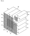
- a plurality of prismatic columnar honeycomb segments 51 and 52 shown in Fig. 10 may be employed.
- the plugged honeycomb structure 50 may include four inner honeycomb segments 51 in total combined in two columns and two rows, and twelve outer honeycomb segments 52 in total arranged around the four inner honeycomb segments 51 combined in the form of a square sectional shape, and the plugged honeycomb structure may be constructed finally by using the 16 honeycomb segments 51 and 52.
- plugging portions 56 are alternately arranged in respective cells 55 of second inflow side end faces 53 and second outflow side end faces 54 of the inner honeycomb segments 51, in the form of a lattice to form a checkerboard pattern.
- the plugging portions 56 are not arranged in any cells 55 of second inflow side end faces 53 and second outflow side end faces 54 of the outer honeycomb segments 52 and the cells are opened to the outside.
- each of the second inflow side end faces 53 and the second outflow side end faces 54 of the four inner honeycomb segments 51 corresponds to an end face central region C in the present invention
- each of the second inflow side end faces 53 and the second outflow side end faces 54 of the twelve outer honeycomb segments 52 corresponds to an end face circumferential region O in the present invention.
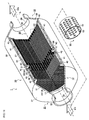
- such an exhaust gas purifying device 60 as shown in Fig. 11 and Fig. 12 may be constituted. It is to be noted that in Fig. 11 and Fig. 12 , the same constitution as in the above-mentioned exhaust gas purifying device 1 is denoted with the same numerals and detailed description thereof is omitted.
- a cylindrical rectifying portion 61 in which a plurality of round hole portions 63 are made in a cylindrical member 62 forming a circumferential wall, between an exhaust gas inflow portion 31 of a can member 30 and a first inflow side end face 11 of a honeycomb catalyst body 10.
- an outer diameter of the cylindrical rectifying portion 61 matches an inner diameter of an inflow port 33 of the exhaust gas inflow portion 31, and an exhaust gas EG introduced into the can member 30 is controlled to surely pass through the rectifying portion 61.
- the rectifying portion 61 is constituted by using a metal material such as stainless steel so that the rectifying portion can resist the high-temperature exhaust gas EG even when exposed to the gas.
- the rectifying portion 61 mentioned above is disposed in the can member 30, and hence it is possible to control the flow of the exhaust gas EG from the inflow port 33 to the first inflow side end face 11 of the honeycomb catalyst body 10. Further specifically, due to a difference in flow rate (or flow speed) of the exhaust gas EG introduced into the exhaust gas purifying device 60, a behavior of the exhaust gas EG in the can member 30 changes.
- the plugged honeycomb structure 20 (e.g., see Fig. 5 ) conforming to an arrangement standard in which the plurality of plugging portions 26 are arranged in the end face central region C, whereas the plugging portions 26 are not arranged in an end face circumferential region O, a pressure loss difference between the region C and the region O increases, and hence the exhaust gas EG easily flows toward the end face circumferential region O.
- the trapping efficiency of the plugged honeycomb structure 20 in the low flow rate state remarkably deteriorates, and there is a high possibility that the particulate matter is emitted as it is to the outside without being sufficiently trapped.
- This problem can be eliminated by the exhaust gas purifying device 60 of the other example constitution of the present invention.
- the cylindrical rectifying portion 61 is disposed between the inflow port 33 and the honeycomb catalyst body 10, so that there can be suppressed spreading of the exhaust gas EG in the direction perpendicular to the axial direction in the low flow rate state, and the exhaust gas EG can be guided toward the vicinity of a middle (the end face central region C) in the honeycomb catalyst body 10 and the plugged honeycomb structure 20.
- the flow of the exhaust gas EG can be rectified so that a part of the exhaust gas EG is dispersed to flow toward the direction perpendicular to the axial direction through the plurality of hole portions 63 disposed in the rectifying portion 61.
- the rectifying portion 61 for use in the exhaust gas purifying device 60 of the other example constitution of the present invention is not limited to the rectifying portion shown in Fig. 11 and Fig. 12 .
- Fig. 11 and the like show that the plurality of perfectly circular hole portions 63 are disposed in the cylindrical member 62, but the present invention is not limited to this example. Holes of various shapes such as elliptic holes, square holes and linear holes are usable, as long as the flow of the exhaust gas EG can be rectified in each of the low flow rate state and the high flow rate state.
- the number of the hole portions 63 to be made in the cylindrical member 62, a size such as a hole diameter, a layout of the respective hole portions 63 and the like can optionally be determined.
- Table 1 mentioned below shows a summary of a diameter, a length, L1/D1, a cell density, a partition wall thickness, a porosity, pore diameters and a catalyst loading ratio of a honeycomb catalyst body, a diameter, a length, L1/L2, a cell density, a partition wall thickness, a porosity, pore diameters, an arrangement standard and a catalyst loading ratio of a plugged honeycomb structure, and a distance between the honeycomb catalyst body and the plugged honeycomb structure (a distance between carriers) in each of Examples 1 to 18 and Comparative Example 1 of an exhaust gas purifying device of the present invention.
- Comparative Example 1 indicates the exhaust gas purifying device using a plugged honeycomb structure constituted in a conventional arrangement standard pattern in which plugging portions are alternately arranged. Furthermore, Example 1 and Examples 7 to 17 indicate the exhaust gas purifying devices in each of which plugging portions are arranged in accordance with an arrangement standard of the above-mentioned third pattern P3, and Examples 2, 3 and 4 indicate the exhaust gas purifying devices in which plugging portions are arranged in accordance with arrangement standards of the above-mentioned fourth pattern P4, fifth pattern P5 and sixth pattern P6, respectively.
- Example 5 is the exhaust gas purifying device in which plugging portions are arranged in a first pattern P1 over the whole surface of a second inflow side end face and the plugging portions are arranged in a second pattern P2 only in the vicinity of a center of a second outflow side end face.
- Example 6 is the exhaust gas purifying device in which plugging portions are arranged in the second pattern P2 only in the vicinity of a center of a second inflow side end face and the plugging portions are arranged in the second pattern P2 only in the vicinity of a center of a second outflow side end face.
- Table 1 Honeycomb catalyst body Distance between carriers Plugged honeycomb structure Dia. Length L1/D1 Cell density Partition wall thickness Porosity Pore dia.
- the exhaust gas purifying device concerned with each of the above-mentioned examples and comparative example was attached to an exhaust system of a car in which a direct injection type gasoline engine having a displacement of 2.0 liters was mounted. Afterward, there were measured emissions of carbon monoxide (CO), hydrocarbons (HC) and nitrogen oxides (NO x ) in an exhaust gas when the car was driven in accordance with driving conditions of Worldwide harmonized Light-duty driving Test Cycle (WLTC) as a vehicle test by use of a chassis dynamometer, to obtain an emission value.
- CO carbon monoxide
- HC hydrocarbons
- NO x nitrogen oxides
- the obtained emission value was compared with a value of Comparative Example 1 of a reference, a case where a value of all components of carbon monoxide, hydrocarbons and nitrogen oxides was 20% or less was evaluated as "A”, and a case where the value was in a range of 5 to 20% was evaluated as "B".
- Table 2 shows "a purifying ratio (CO, HC, NO x )" as an evaluation item concerned with measurement of the purifying ratio.
- the exhaust gas purifying device concerned with each of the examples and comparative example was attached to the exhaust system of the car in which the direct injection type gasoline engine having the displacement of 2.0 liters was mounted. Afterward, there was measured the number of the particles of the PM to be emitted in an exhaust gas when the car was driven in accordance with the driving conditions of Worldwide harmonized Light-duty driving Test Cycle (WLTC) as the vehicle test by use of the chassis dynamometer, on the basis of a method conforming to European EURO6 proposed regulations.
- WLTC Worldwide harmonized Light-duty driving Test Cycle
- Example 1 A A A A Example 2 A A A A A Example 3 A A A A Example 4 A A A A A Example 5 A B A B Example 6 A B A B Example 7 B A A B Example 8 B A A B Example 9 A A A A Example 10 A A A A Example 11 B A A B Example 12 A A A A Example 13 A A B B Example 14 B A A B Example 15 A A A A Example 16 A A B B Example 17 A A A A Example 18 A A A A A
- each of the purifying ratio, the number of the particles of the PM to be emitted and the pressure loss was evaluated as "A" and the general evaluation was also A. That is, in the exhaust gas purifying device of the present invention, it is indicated that each of the arrangement standards of the plugging portions concerned with the third pattern P3 to the sixth pattern P6 suggested in advance has effects of an excellent purifying efficiency, a smaller number of the particles of the PM to be emitted and a low pressure loss.
- the evaluation of the purifying ratio (CO, HC, NO x ) was "A". It has been confirmed that the purifying ratio (CO, HC, NO x ) is influenced by a relation between the length and the diameter of the honeycomb catalyst body for use in the exhaust gas purifying device and a relation in length between the honeycomb catalyst body and the plugged honeycomb structure.
- Example 14 In the exhaust gas purifying device in which the distance between the carriers was 30 mm as stipulated in the present invention (Example 14), it was confirmed that a purifying efficiency decreased, and in the exhaust gas purifying device in which the distance between the carriers was in the above-mentioned range (Example 15), it was confirmed that an excellent purifying efficiency was indicated. That is, it is preferable that the distance between the carriers of the honeycomb catalyst body and the plugged honeycomb structure is adjusted into the above-mentioned range.
- Example 16 In the exhaust gas purifying device in which the amount of the catalyst to be loaded onto the plugged honeycomb structure was in excess of 120 g/L (Example 16), it was confirmed that the pressure loss increased, and in the exhaust gas purifying device in which the amount of the catalyst to be loaded onto the plugged honeycomb structure was 120 g/L or less (Example 17), it was confirmed that an excellent pressure loss was indicated.
- Example 18 In the exhaust gas purifying device of the other example constitution (Example 18) in which a cylindrical rectifying portion was disposed in the can member of the exhaust gas purifying device of Example 6, the evaluation of the number of the particles of the PM to be emitted enhanced from B to A as compared with Example 6. That is, improvement of the number of the particles of the PM to be emitted can be recognized due to the addition of the rectifying portion, and it can be recognized that each evaluation of A is maintained without influencing the purifying ratio or the pressure loss. Therefore, as the general evaluation, the exhaust gas purifying device of Example 18 was A.
- An exhaust gas purifying device of the present invention can efficiently remove a particulate matter included in an exhaust gas, can exert a high purifying performance even immediately after start of an engine without increasing a pressure loss, and is especially useful in performing purification of the exhaust gas of a direct injection type gasoline engine.
Landscapes
- Chemical & Material Sciences (AREA)
- Engineering & Computer Science (AREA)
- Geometry (AREA)
- Physics & Mathematics (AREA)
- Chemical Kinetics & Catalysis (AREA)
- Combustion & Propulsion (AREA)
- Mechanical Engineering (AREA)
- General Engineering & Computer Science (AREA)
- Health & Medical Sciences (AREA)
- Oil, Petroleum & Natural Gas (AREA)
- Biomedical Technology (AREA)
- Environmental & Geological Engineering (AREA)
- Analytical Chemistry (AREA)
- General Chemical & Material Sciences (AREA)
- Ceramic Engineering (AREA)
- Toxicology (AREA)
- Materials Engineering (AREA)
- Organic Chemistry (AREA)
- Catalysts (AREA)
- Exhaust Gas Treatment By Means Of Catalyst (AREA)
- Exhaust Gas After Treatment (AREA)
Applications Claiming Priority (3)
| Application Number | Priority Date | Filing Date | Title |
|---|---|---|---|
| JP2015185814 | 2015-09-18 | ||
| JP2016090014 | 2016-04-28 | ||
| JP2016152169A JP6702823B2 (ja) | 2015-09-18 | 2016-08-02 | 排気ガス浄化装置 |
Publications (1)
| Publication Number | Publication Date |
|---|---|
| EP3144048A1 true EP3144048A1 (fr) | 2017-03-22 |
Family
ID=57123785
Family Applications (1)
| Application Number | Title | Priority Date | Filing Date |
|---|---|---|---|
| EP16188945.6A Pending EP3144048A1 (fr) | 2015-09-18 | 2016-09-15 | Dispositif de purification des gaz d'échappement |
Country Status (3)
| Country | Link |
|---|---|
| US (1) | US9932873B2 (fr) |
| EP (1) | EP3144048A1 (fr) |
| CN (1) | CN106540496B (fr) |
Families Citing this family (13)
| Publication number | Priority date | Publication date | Assignee | Title |
|---|---|---|---|---|
| US10632458B2 (en) * | 2015-11-30 | 2020-04-28 | Corning Incorporated | Compound honeycomb body, exhaust gas treatment article, exhaust system and methods of manufacturing same |
| JP6829979B2 (ja) * | 2016-10-19 | 2021-02-17 | 日本碍子株式会社 | 目封止ハニカム構造体 |
| JP6767235B2 (ja) * | 2016-10-19 | 2020-10-14 | 日本碍子株式会社 | 目封止ハニカム構造体 |
| CN106939812A (zh) * | 2017-04-01 | 2017-07-11 | 江门市资迪科技环保有限公司 | 一种分级式氧化颗粒捕集器及其制作方法 |
| CN109695496B (zh) * | 2017-10-23 | 2021-03-16 | 本田技研工业株式会社 | 内燃机的废气净化装置 |
| JP2019084482A (ja) * | 2017-11-03 | 2019-06-06 | 株式会社デンソー | 排ガス浄化装置 |
| US20190153923A1 (en) * | 2017-11-22 | 2019-05-23 | Jumbomaw Technology Co., Ltd. | Two-sectioned back-pressured catalytic converter |
| JP7037985B2 (ja) * | 2018-03-30 | 2022-03-17 | 日本碍子株式会社 | ハニカムフィルタ |
| JP7049155B2 (ja) * | 2018-03-30 | 2022-04-06 | 日本碍子株式会社 | ハニカムフィルタ |
| JP6939709B2 (ja) * | 2018-06-05 | 2021-09-22 | トヨタ自動車株式会社 | 電気化学リアクタ |
| JP7211893B2 (ja) * | 2019-05-24 | 2023-01-24 | トヨタ自動車株式会社 | 排ガス浄化装置 |
| CN110201727B (zh) * | 2019-06-06 | 2022-04-19 | 无锡威孚环保催化剂有限公司 | 颗粒捕集用催化剂载体的预处理方法 |
| JP7381372B2 (ja) | 2020-03-12 | 2023-11-15 | トヨタ自動車株式会社 | 排ガス浄化装置 |
Citations (3)
| Publication number | Priority date | Publication date | Assignee | Title |
|---|---|---|---|---|
| JP2003254034A (ja) | 2002-02-26 | 2003-09-10 | Ngk Insulators Ltd | ハニカムフィルタ |
| EP2380649A1 (fr) * | 2010-02-16 | 2011-10-26 | NGK Insulators, Ltd. | Dispositif de purification des gaz d'échappement |
| EP2698191A1 (fr) * | 2012-08-13 | 2014-02-19 | NGK Insulators, Ltd. | Structure en nid d'abeille raccordée |
Family Cites Families (5)
| Publication number | Priority date | Publication date | Assignee | Title |
|---|---|---|---|---|
| JP2001098925A (ja) * | 1999-09-30 | 2001-04-10 | Ibiden Co Ltd | 排気ガス浄化装置及びそのフィルタ |
| EP1312776A3 (fr) * | 2001-11-16 | 2004-05-12 | Isuzu Motors Limited | Système pour la purification de gaz d'échappement |
| US7238217B2 (en) * | 2004-04-23 | 2007-07-03 | Corning Incorporated | Diesel engine exhaust filters |
| CN1954137B (zh) * | 2005-07-21 | 2011-12-21 | 揖斐电株式会社 | 蜂窝结构体以及废气净化装置 |
| JP5708670B2 (ja) * | 2013-01-18 | 2015-04-30 | 株式会社デンソー | ハニカム構造体 |
-
2016
- 2016-09-07 US US15/258,218 patent/US9932873B2/en active Active
- 2016-09-12 CN CN201610816683.7A patent/CN106540496B/zh active Active
- 2016-09-15 EP EP16188945.6A patent/EP3144048A1/fr active Pending
Patent Citations (4)
| Publication number | Priority date | Publication date | Assignee | Title |
|---|---|---|---|---|
| JP2003254034A (ja) | 2002-02-26 | 2003-09-10 | Ngk Insulators Ltd | ハニカムフィルタ |
| EP2380649A1 (fr) * | 2010-02-16 | 2011-10-26 | NGK Insulators, Ltd. | Dispositif de purification des gaz d'échappement |
| JP5584487B2 (ja) | 2010-02-16 | 2014-09-03 | 日本碍子株式会社 | 排気ガス浄化装置 |
| EP2698191A1 (fr) * | 2012-08-13 | 2014-02-19 | NGK Insulators, Ltd. | Structure en nid d'abeille raccordée |
Also Published As
| Publication number | Publication date |
|---|---|
| CN106540496A (zh) | 2017-03-29 |
| US9932873B2 (en) | 2018-04-03 |
| CN106540496B (zh) | 2020-07-14 |
| US20170082005A1 (en) | 2017-03-23 |
Similar Documents
| Publication | Publication Date | Title |
|---|---|---|
| US9932873B2 (en) | Exhaust gas purifying device | |
| US9700842B2 (en) | Honeycomb filter | |
| US7056365B2 (en) | Honeycomb structure, and honeycomb filter and converter system both using the same | |
| EP2737945B1 (fr) | Corps de catalyseur en nid d'abeille | |
| US10040016B1 (en) | Plugged honeycomb structure | |
| EP1247556B1 (fr) | Structure a nid d'abeilles avec alveoles triangulaires | |
| JP5202298B2 (ja) | ハニカム触媒体および排気ガス処理システム | |
| EP2380649B1 (fr) | Dispositif de purification des gaz d'échappement | |
| EP1920840A1 (fr) | Structure en nid d' abeille et structure catalytique en nid d' abeille | |
| US9803596B2 (en) | Honeycomb filter | |
| EP2364765A1 (fr) | Corps de catalyseur en nid d'abeille | |
| EP1974791A1 (fr) | Structure alvéolaire et son procédé de fabrication | |
| KR20120095995A (ko) | 존형 촉매화 매연 필터 | |
| US10315192B2 (en) | Honeycomb structure | |
| EP2737944B1 (fr) | Corps de catalyseur en nid d'abeille | |
| US10232300B2 (en) | Plugged honeycomb structure | |
| US20220193649A1 (en) | Exhaust purification filter | |
| KR20090108698A (ko) | 파상 벽을 갖는 가스 여과 구조체 | |
| EP2221098B1 (fr) | Structure en nid d'abeille | |
| JP6702823B2 (ja) | 排気ガス浄化装置 | |
| US10695708B2 (en) | Plugged honeycomb structure | |
| JP2012184658A (ja) | 排ガス浄化装置 | |
| US20200306739A1 (en) | Honeycomb filter | |
| JP2020121307A (ja) | ハニカム構造型触媒、排ガス浄化装置及び排ガス浄化方法 | |
| EP2236190B1 (fr) | Filtre en nid d'abeille et son procédé de fabrication |
Legal Events
| Date | Code | Title | Description |
|---|---|---|---|
| PUAI | Public reference made under article 153(3) epc to a published international application that has entered the european phase |
Free format text: ORIGINAL CODE: 0009012 |
|
| STAA | Information on the status of an ep patent application or granted ep patent |
Free format text: STATUS: THE APPLICATION HAS BEEN PUBLISHED |
|
| AK | Designated contracting states |
Kind code of ref document: A1 Designated state(s): AL AT BE BG CH CY CZ DE DK EE ES FI FR GB GR HR HU IE IS IT LI LT LU LV MC MK MT NL NO PL PT RO RS SE SI SK SM TR |
|
| AX | Request for extension of the european patent |
Extension state: BA ME |
|
| STAA | Information on the status of an ep patent application or granted ep patent |
Free format text: STATUS: REQUEST FOR EXAMINATION WAS MADE |
|
| 17P | Request for examination filed |
Effective date: 20170731 |
|
| RBV | Designated contracting states (corrected) |
Designated state(s): AL AT BE BG CH CY CZ DE DK EE ES FI FR GB GR HR HU IE IS IT LI LT LU LV MC MK MT NL NO PL PT RO RS SE SI SK SM TR |
|
| STAA | Information on the status of an ep patent application or granted ep patent |
Free format text: STATUS: EXAMINATION IS IN PROGRESS |
|
| 17Q | First examination report despatched |
Effective date: 20210608 |
|
| STAA | Information on the status of an ep patent application or granted ep patent |
Free format text: STATUS: EXAMINATION IS IN PROGRESS |