EP3143391B1 - Photoacoustic apparatus - Google Patents
Photoacoustic apparatus Download PDFInfo
- Publication number
- EP3143391B1 EP3143391B1 EP15726356.7A EP15726356A EP3143391B1 EP 3143391 B1 EP3143391 B1 EP 3143391B1 EP 15726356 A EP15726356 A EP 15726356A EP 3143391 B1 EP3143391 B1 EP 3143391B1
- Authority
- EP
- European Patent Office
- Prior art keywords
- supporting member
- target position
- reception signals
- transducers
- subject
- Prior art date
- Legal status (The legal status is an assumption and is not a legal conclusion. Google has not performed a legal analysis and makes no representation as to the accuracy of the status listed.)
- Active
Links
- 238000012545 processing Methods 0.000 claims description 59
- 238000005259 measurement Methods 0.000 claims description 12
- 230000006870 function Effects 0.000 claims description 10
- 230000007423 decrease Effects 0.000 claims description 9
- 238000003672 processing method Methods 0.000 claims description 4
- 239000000523 sample Substances 0.000 description 25
- 238000010586 diagram Methods 0.000 description 15
- 230000035945 sensitivity Effects 0.000 description 15
- 230000003287 optical effect Effects 0.000 description 10
- 230000007246 mechanism Effects 0.000 description 8
- 238000000034 method Methods 0.000 description 7
- 238000003860 storage Methods 0.000 description 6
- 230000008859 change Effects 0.000 description 4
- 238000003384 imaging method Methods 0.000 description 4
- 239000000463 material Substances 0.000 description 4
- 238000004364 calculation method Methods 0.000 description 3
- 238000005520 cutting process Methods 0.000 description 3
- 230000010355 oscillation Effects 0.000 description 3
- 239000007787 solid Substances 0.000 description 3
- INGWEZCOABYORO-UHFFFAOYSA-N 2-(furan-2-yl)-7-methyl-1h-1,8-naphthyridin-4-one Chemical compound N=1C2=NC(C)=CC=C2C(O)=CC=1C1=CC=CO1 INGWEZCOABYORO-UHFFFAOYSA-N 0.000 description 2
- 108010054147 Hemoglobins Proteins 0.000 description 2
- 102000001554 Hemoglobins Human genes 0.000 description 2
- 108010064719 Oxyhemoglobins Proteins 0.000 description 2
- 239000002033 PVDF binder Substances 0.000 description 2
- 238000002591 computed tomography Methods 0.000 description 2
- 108010002255 deoxyhemoglobin Proteins 0.000 description 2
- 238000005401 electroluminescence Methods 0.000 description 2
- 230000001678 irradiating effect Effects 0.000 description 2
- 229910052451 lead zirconate titanate Inorganic materials 0.000 description 2
- 230000004048 modification Effects 0.000 description 2
- 238000012986 modification Methods 0.000 description 2
- 239000013307 optical fiber Substances 0.000 description 2
- 238000010895 photoacoustic effect Methods 0.000 description 2
- 229920002981 polyvinylidene fluoride Polymers 0.000 description 2
- 230000004044 response Effects 0.000 description 2
- 238000012552 review Methods 0.000 description 2
- 239000004065 semiconductor Substances 0.000 description 2
- 239000000126 substance Substances 0.000 description 2
- 238000012935 Averaging Methods 0.000 description 1
- 238000010521 absorption reaction Methods 0.000 description 1
- QVGXLLKOCUKJST-UHFFFAOYSA-N atomic oxygen Chemical compound [O] QVGXLLKOCUKJST-UHFFFAOYSA-N 0.000 description 1
- 230000008901 benefit Effects 0.000 description 1
- 210000004204 blood vessel Anatomy 0.000 description 1
- 210000000481 breast Anatomy 0.000 description 1
- 229910010293 ceramic material Inorganic materials 0.000 description 1
- 230000000295 complement effect Effects 0.000 description 1
- 238000001514 detection method Methods 0.000 description 1
- 238000009792 diffusion process Methods 0.000 description 1
- 238000006073 displacement reaction Methods 0.000 description 1
- 238000009826 distribution Methods 0.000 description 1
- 239000010408 film Substances 0.000 description 1
- 239000007789 gas Substances 0.000 description 1
- 229920000126 latex Polymers 0.000 description 1
- HFGPZNIAWCZYJU-UHFFFAOYSA-N lead zirconate titanate Chemical compound [O-2].[O-2].[O-2].[O-2].[O-2].[Ti+4].[Zr+4].[Pb+2] HFGPZNIAWCZYJU-UHFFFAOYSA-N 0.000 description 1
- 230000031700 light absorption Effects 0.000 description 1
- 239000004973 liquid crystal related substance Substances 0.000 description 1
- 238000004519 manufacturing process Methods 0.000 description 1
- 239000007769 metal material Substances 0.000 description 1
- 229910044991 metal oxide Inorganic materials 0.000 description 1
- 150000004706 metal oxides Chemical class 0.000 description 1
- 239000001301 oxygen Substances 0.000 description 1
- 229910052760 oxygen Inorganic materials 0.000 description 1
- 229920000642 polymer Polymers 0.000 description 1
- 238000005086 pumping Methods 0.000 description 1
- 229920003002 synthetic resin Polymers 0.000 description 1
- 239000000057 synthetic resin Substances 0.000 description 1
- 239000010409 thin film Substances 0.000 description 1
- 238000002834 transmittance Methods 0.000 description 1
Images


Classifications
-
- G—PHYSICS
- G01—MEASURING; TESTING
- G01N—INVESTIGATING OR ANALYSING MATERIALS BY DETERMINING THEIR CHEMICAL OR PHYSICAL PROPERTIES
- G01N21/00—Investigating or analysing materials by the use of optical means, i.e. using sub-millimetre waves, infrared, visible or ultraviolet light
- G01N21/17—Systems in which incident light is modified in accordance with the properties of the material investigated
- G01N21/1702—Systems in which incident light is modified in accordance with the properties of the material investigated with opto-acoustic detection, e.g. for gases or analysing solids
-
- A—HUMAN NECESSITIES
- A61—MEDICAL OR VETERINARY SCIENCE; HYGIENE
- A61B—DIAGNOSIS; SURGERY; IDENTIFICATION
- A61B5/00—Measuring for diagnostic purposes; Identification of persons
- A61B5/0093—Detecting, measuring or recording by applying one single type of energy and measuring its conversion into another type of energy
- A61B5/0095—Detecting, measuring or recording by applying one single type of energy and measuring its conversion into another type of energy by applying light and detecting acoustic waves, i.e. photoacoustic measurements
-
- G—PHYSICS
- G01—MEASURING; TESTING
- G01N—INVESTIGATING OR ANALYSING MATERIALS BY DETERMINING THEIR CHEMICAL OR PHYSICAL PROPERTIES
- G01N29/00—Investigating or analysing materials by the use of ultrasonic, sonic or infrasonic waves; Visualisation of the interior of objects by transmitting ultrasonic or sonic waves through the object
- G01N29/22—Details, e.g. general constructional or apparatus details
- G01N29/24—Probes
- G01N29/2418—Probes using optoacoustic interaction with the material, e.g. laser radiation, photoacoustics
-
- G—PHYSICS
- G01—MEASURING; TESTING
- G01N—INVESTIGATING OR ANALYSING MATERIALS BY DETERMINING THEIR CHEMICAL OR PHYSICAL PROPERTIES
- G01N21/00—Investigating or analysing materials by the use of optical means, i.e. using sub-millimetre waves, infrared, visible or ultraviolet light
- G01N21/17—Systems in which incident light is modified in accordance with the properties of the material investigated
- G01N21/1702—Systems in which incident light is modified in accordance with the properties of the material investigated with opto-acoustic detection, e.g. for gases or analysing solids
- G01N2021/1706—Systems in which incident light is modified in accordance with the properties of the material investigated with opto-acoustic detection, e.g. for gases or analysing solids in solids
-
- G—PHYSICS
- G01—MEASURING; TESTING
- G01N—INVESTIGATING OR ANALYSING MATERIALS BY DETERMINING THEIR CHEMICAL OR PHYSICAL PROPERTIES
- G01N21/00—Investigating or analysing materials by the use of optical means, i.e. using sub-millimetre waves, infrared, visible or ultraviolet light
- G01N21/17—Systems in which incident light is modified in accordance with the properties of the material investigated
- G01N21/1702—Systems in which incident light is modified in accordance with the properties of the material investigated with opto-acoustic detection, e.g. for gases or analysing solids
- G01N2021/1708—Systems in which incident light is modified in accordance with the properties of the material investigated with opto-acoustic detection, e.g. for gases or analysing solids with piezotransducers
Definitions
- the present invention relates to a photoacoustic apparatus for obtaining subject information by using a photoacoustic effect.
- PTL 1 describes a photoacoustic apparatus that performs photoacoustic imaging by using a probe in which transducers are arranged on a hemisphere. With this probe, photoacoustic waves generated in a specific region can be received with high sensitivity. Thus, the resolution of subject information in the specific region is high. Also, PTL 1 describes a technique in which scanning is performed on a certain plane by using the probe, and the probe receives acoustic waves at a plurality of positions so as to obtain reception signals. Also, PTL 1 describes a technique in which reconstruction is performed after obtaining the reception signals at the plurality of positions.
- WO 2012/108172 discloses a photoacoustic apparatus as claimed in the pre-characterizing portion of claim 1 herein.
- WO 2011/062125 discloses an image forming apparatus having acoustic transducers; and an image processing unit which calculates intensity of acoustic waves irradiated from regions inside a subject respectively by processing received signals, which are output from the acoustic transducers, by a Fourier-domain method.
- a photoacoustic apparatus as claimed in claim 1 herein.
- a signal processing method as claimed in claim 17 herein.
- a photoacoustic apparatus obtains subject information on the basis of reception signals of photoacoustic waves.
- Subject information is information about a subject, which is obtained from reception signals of photoacoustic waves generated by a photoacoustic effect.
- subject information represents a generated sound pressure (initial sound pressure), a light energy absorption density, a light absorption coefficient, a concentration of a substance constituting a tissue, and so forth.
- a concentration of a substance is, for example, oxygen saturation, oxyhemoglobin concentration, deoxyhemoglobin concentration, and total hemoglobin concentration.
- the total hemoglobin concentration is the sum of oxyhemoglobin concentration and deoxyhemoglobin concentration.
- the photoacoustic apparatus stores, in a memory, a group of time-series reception signals output from the probe as reception signal data. Also, the photoacoustic apparatus according to this embodiment obtains subject information at individual target positions in a region of interest (ROI) by using the reception signal data that has been obtained through a plurality of times of reception of acoustic waves and stored in the memory.
- a target position is a pixel in a case where a two-dimensional ROI is set, and is a voxel in a case where a three-dimensional ROI is set.
- a plurality of time-series signals output from the plurality of transducers in response to one irradiation with light when the probe and a subject have a certain relative positional relationship are referred to as "a group of reception signals”.
- groups of reception signals output from the plurality of transducers in response to a plurality of times of irradiation with light in a plurality of states where the relative positional relationship between the probe and a subject differs are referred to as "a plurality of groups of reception signals”.
- the resolution of the subject information is typically the highest at a certain position where directional axes converge.
- the resolution of the subject information has a tendency to decrease with increasing distance from the certain position.
- it is estimated that the probe is able to receive, with relatively high sensitivity, acoustic waves generated in a certain region ranging from a position where the resolution is the highest to a position where the resolution is half the highest resolution.
- the region ranging from the position where the resolution is the highest to the position where the resolution is half the highest resolution is referred to as a "highly-sensitive region".
- a plurality of groups of reception signals that have been obtained over a plurality of times from the following point of view are weighted, and thereby subject information at a target positon is obtained.
- a large weight may be assigned to a reception signal output from a transducer oriented to the target position. Accordingly, the weight of a reception signal output from the transducer that has received, with high sensitivity, photoacoustic waves generated at the target position can be increased, and thus the weight of a reception signal having a high S/N ratio can be increased. As a result, the S/N ratio of subject information at the target position reconstructed by using such a weighted reception signal can also be increased. That is, the quantitativity and resolution of subject information at the target position can be increased. Further, with such weighting being applied to all target positions, the quantitativity and resolution at all positions of a reconstructed image can be increased.
- the individual transducers arranged in the probe according to this embodiment are able to receive acoustic waves generated in a highly-sensitive region with high sensitivity.
- a larger weight may be assigned to a group of reception signals obtained by the probe when the highly-sensitive region is closer to a target position, among a plurality of groups of reception signals stored in the memory. That is, a weight to be assigned to a group of reception signals obtained by the probe may be determined in accordance with the relative positions of the target position and the probe. Accordingly, a large weight can be assigned to a group of reception signals estimated to have been received with high sensitivity.
- the quantitativity and resolution at individual target positions can be easily increased by uniformly determining a weight for the reception signals output from the individual transducers when the target position and the probe have a certain relative positional relationship.
- the amount of calculation for determining a weight can be reduced compared to the case of calculating weights for individual transducers in accordance with the relative positions of the individual transducers and the target position.
- weights calculated in advance are stored in a memory and weighting is performed by reading a weight from the memory.
- weights for individual relative positions of the individual transducers and a target position are not stored, and it is sufficient to store a weight corresponding to the relative positions of the probe and the target position. Therefore, according to this embodiment, the amount of data of weights can be reduced, and accordingly the capacity of the memory for storing the data of weights can be reduced.
- the photoacoustic apparatus is able to arbitrarily assign a weight to a group of reception signals stored in the memory, and is thus able to change the weight to be assigned to the signals in accordance with a purpose after receiving the signals.
- a weight may be assigned to reception signals at individual target positions in an ROI from the above-described point of view. Accordingly, at each target position in the ROI, the contrast between a reconstructed image at the target position (signal component) and a reconstruction artifact (noise component) increases.
- the same weight may be assigned to the individual transducers arranged in the probe.
- the photoacoustic apparatus assigns, from the above-described point of view, a weight to a plurality of groups of reception signals that have been obtained by moving the plurality of transducers that are arranged so as to be able to receive acoustic waves generated in a highly-sensitive region with high sensitivity. Accordingly, at each target position in the ROI, the contrast between a reconstructed image at the target position (signal component) and a reconstruction artifact (noise component) increases, and the resolution increases.
- a certain horizontal axis is referred to as an x-axis
- a horizontal axis perpendicular to the x-axis is referred to as a y-axis
- an axis perpendicular to the x- and y-axes is referred to as a z-axis.
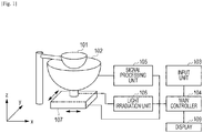
- the photoacoustic apparatus includes a holding cup 101, a probe 102, an input unit 103, a main controller 104, a signal processing unit 105, a light irradiation unit 106, a driving device 107, and a display 109.
- the holding cup 101 is used to fix a subject so that the subject is not moved during image capturing, and is a hemispherical cup made of a synthetic resin.
- the holding cup 101 may be made of a thin film of latex rubber or the like as long as the subject can be fixed.
- the holding cup 101 may be made of a material having a high transmittance for light so as to suppress attenuation of pulsed light applied to the subject.
- the holding cup 101 may be made of a material having an acoustic impedance similar to the acoustic impedance of a subject so as to reduce reflection of acoustic waves at the interface of the subject.
- the probe 102 is constituted by a plurality of transducers 201 and a supporting member 202 for supporting the plurality of transducers 201.
- the supporting member 202 according to this embodiment is a hemispherical casing in which the plurality of transducers 201 are arranged.
- the transducers 201 may be made of a piezoelectric ceramic material represented by lead zirconate titanate (PZT), a high polymer piezoelectric film material represented by polyvinylidene fluoride (PVDF), or the like.
- An element other than a piezoelectric element may be used.
- a capacitive micro-machined ultrasonic transducer (cMUT) a transducer using a Fabry-Perot interferometer, or the like may be used.
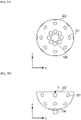
- the supporting member 202 supports the plurality of transducers 201 that are radially arranged on the inner surface of the hemisphere.
- the manner of arrangement is not limited thereto.
- the transducers 201 may be spirally arranged.
- a light exit 108 is provided at a bottom portion (pole) of the hemispherical supporting member 202.
- the inner side of the supporting member 202 may be filled with an acoustic matching material.
- the plurality of transducers 201 are arranged along the hemispherical surface as illustrated in Figs. 2A and 2B .
- a point X indicates the curvature center of the hemispherical supporting member 202.
- the supporting member 202 supports the plurality of transducers 201 such that the directional axes of the transducers 201 converge. That is, the position of the curvature center of the supporting member 202 and the position at which the directional axes of the plurality of transducers 201 converge can be estimated on the basis of the position of the supporting member 202.
- a region that can be visualized with high accuracy is formed around the curvature center.
- a region that can be visualized with high accuracy is referred to as a highly-sensitive region.
- the highly-sensitive region can be considered as a substantially spherical region having a radius d th expressed by Equation (1), with the curvature center at which a maximum resolution R H is obtained being the center.
- R represents the minimum resolution of a highly-sensitive region G
- r 0 represents the radius of the hemispherical supporting member 202
- ⁇ d represents the diameter of the transducer 201.
- R may be, for example, half of the maximum resolution that can be obtained at the curvature center.
- the range of the highly-sensitive region at each position that is two-dimensionally scanned by the probe can be estimated on the basis of the spherical shape and the position of the probe (that is, the curvature center) by using Equation (1).
- the arrangement of the plurality of transducers 201 is not limited to the example of the hemispherical shape illustrated in Figs. 2A and 2B . Any arrangement may be adopted as long as the directional axes of the plurality of transducers 201 converge so as to form a desired highly-sensitive region. That is, any arrangement may be adopted as long as the plurality of transducers 201 are arranged along a curved surface so as to form a desired highly-sensitive region.
- a curved surface includes a surface of a perfect sphere and a surface of a hemisphere having an opening.
- a curved surface includes an uneven surface that can be regarded as a spherical surface, and a surface of an ellipsoid (a shape formed by expanding an ellipse into a three dimensional shape, the surface of which is formed of a quadric surface) that can be regarded as a spherical surface.
- the directional axes of the transducers converge the most at the curvature center of the shape of the supporting member.
- the hemispherical supporting member 202 described in this embodiment is also an example of a supporting member having a shape formed by cutting a sphere along a certain cross section. In this description, such a shape formed by cutting a sphere along a certain cross section is referred to as "a shape based on a sphere".
- the plurality of transducers supported by the supporting member having such a shape based on a sphere are supported on the spherical surface.
- the directional axes of the individual transducers do not necessarily cross one another as long as a desired highly-sensitive region can be formed. It is sufficient that the directional axes of at least some of the plurality of transducers 201 supported by the supporting member 202 converge in a specific region so that photoacoustic waves generated in the specific region can be received with high sensitivity. That is, it is sufficient that the plurality of transducers 201 are arranged on the supporting member 202 so that at least some of the plurality of transducers 201 are able to receive photoacoustic waves generated in a highly-sensitive region with high sensitivity.
- the supporting member 202 may be formed by using a metallic material or the like having a high mechanical strength.
- the signal processing unit 105 is connected to the transducers 201 via signal lines, AD converts analog reception signals output from the transducers 201, and transmits the converted signals to the main controller 104.
- the signal processing unit 105 may be connected to a light detection sensor provided at the light exit 108, so as to obtain signals in synchronization with emission of pulsed light.
- the light irradiation unit 106 includes a light source that emits light, and an optical system that leads the light emitted from the light source to a subject.
- the light source may be a pulsed light source capable of generating pulsed light of the order of nanoseconds to microseconds.
- the pulsed light may have a pulse width of about 1 to 100 nanoseconds.
- the pulsed light may have a wavelength in the range from about 400 nm to 1600 nm.
- light having a wavelength in the visible range 400 nm or more and 700 nm or less may be used.
- light having a wavelength that is less likely to be absorbed in a background tissues of a living body may be used.
- terahertz waves, microwaves, or radio waves may be used.
- a specific example of the light source is a laser or a light-emitting diode.
- a light source capable of converting an oscillation wavelength may be used.
- a plurality of light sources that oscillate light beams of different wavelengths may be used by switching oscillation or alternately emitting the light beams. Even in a case where a plurality of light sources are used, they are collectively referred to as a light source.
- a solid-state laser such as an Nd:YAG laser or an alexandrite laser
- a pulse laser such as an Nd:YAG laser or an alexandrite laser
- a Ti:sa laser or an optical parametric oscillation (OPO) laser that use Nd:YAG laser light as pumping light may be used.
- the optical system causes pulsed light to travel from the light source to a subject.
- optical devices such as a lens, a mirror, and an optical fiber may be used.
- a light emitter of an optical system may emit pulsed light that has a beam diameter extended by using a diffusion plate or the like.
- a light emitter of an optical system may be constituted by a lens or the like and emit light by focusing a beam diameter in order to increase resolution.
- the light irradiation unit 106 does not include an optical system, and a subject may be directly irradiated with light emitted from the light source.
- the light source of the light irradiation unit 106 is connected to the light exit 108 via an optical fiber serving as the optical system. Pulsed light is emitted from the bottom of the supporting member 202 toward the curvature center of the hemispherical supporting member 202.
- the driving device 107 serving as a driving unit changes the relative positions of a subject and the supporting member 202.
- the driving device 107 moves the supporting member 202 in the x- and y-directions, and includes an electric-powered XY stage on which a stepping motor is mounted.
- the driving device 107 is not limited to a device that two-dimensionally changes the relative positions of a subject and the supporting member 202, and a device that one-dimensionally or three-dimensionally changes the relative positions may be used.
- the driving device 107 includes a guiding mechanism for a movement direction, a driving mechanism for a movement direction, and a position sensor that detects the position of the supporting member 202.
- the supporting member 202 is mounted on the driving device 107, and thus a linear guide or the like resistant to a heavy load may be used as the guiding mechanism.
- the driving mechanism a lead screw mechanism, a link mechanism, a gear mechanism, a hydraulic mechanism, or the like may be used.
- a motor may be used as a driving force.
- As the position sensor a potentiometer including an encoder, a variable resistor, and so forth may be used.
- the relative positions of a subject and the supporting member 202 are changed, and thus the supporting member 202 may be fixed and the subject may be moved.
- a subject supporting member for supporting the subject (not illustrated) may be moved to move the subject. Both of the subject and the supporting member 202 may be moved.
- the movement may be continuously performed, or may be repeatedly performed in certain steps.
- the driving device 107 may be an electric-powered stage, or may be a manually-operated stage.
- the driving device 107 is not limited to the one described above, and any types of device may be used as long as it is configured to be able to move at least one of a subject and the supporting member 202.
- the main controller 104 is connected to the input unit 103, the signal processing unit 105, the light irradiation unit 106, and the driving device 107 via a bus such as a universal serial bus (USB).
- the main controller 104 controls the individual devices, and typically is a built-in personal computer (PC).
- the main controller 104 reconstructs subject information, such as an initial sound pressure generated from a subject, by using a signal received from the signal processing unit 105.
- the main controller 104 includes a central processing unit (CPU) serving as a control unit.
- the main controller 104 includes an arithmetic element such as a CPU or a graphics processing unit (GPU), and an arithmetic circuit such as a field-programmable gate array (FPGA) or an application specific integrated circuit (ASIC). Also, the main controller 104 includes a memory such as a read only memory (ROM), a random access memory (RAM), or a hard disk.
- arithmetic element such as a CPU or a graphics processing unit (GPU)
- FPGA field-programmable gate array
- ASIC application specific integrated circuit
- the main controller 104 includes a memory such as a read only memory (ROM), a random access memory (RAM), or a hard disk.
- the display 109 serving as a display unit displays subject information output from the main controller 104 in the form of a distribution image or numeric data.
- a liquid crystal display or the like is used as the display 109, but another type of display, such as a plasma display, an organic electroluminescence (EL) display, or a field emission display (FED), may be used.
- the display 109 may be provided separately from the photoacoustic apparatus according to an embodiment of the present invention.
- the processing is performed by the main controller 104 which controls the individual units of the photoacoustic apparatus.
- the main controller 104 Upon start of the processing, the main controller 104 transmits an instruction to the driving device 107, and accordingly the driving device 107 moves the supporting member 202 to a predetermined irradiation position (step S301).
- the main controller 104 transmits an instruction to the light irradiation unit 106, and accordingly the light irradiation unit 106 emits pulsed light, so that pulsed light is emitted from the light exit 108 (step S302).
- each of the plurality of transducers 201 receives photoacoustic waves and outputs a reception signal to the signal processing unit 105.
- the signal processing unit 105 starts, in synchronization with emission of pulsed light, signal processing for a group of reception signals.
- an operation of obtaining data of a group of reception signals means an operation of converting a group of time-series reception signals output from the plurality of transducers 201 into digital signals and storing the digital signals in the first memory of the main controller 104.
- data of a group of reception signals is obtained a plurality of times by changing the relative positions of the holding cup 101 and the supporting member 202.
- the main controller 104 determines whether data of a group of reception signals has been obtained a predetermined times (step S304). If data of another group of signals is to be obtained, the processing returns to step S301. As a result, data of a plurality of groups of reception signals corresponding to a plurality of times of irradiation is stored in the first memory of the main controller 104.
- the main controller 104 After signals have been obtained the predetermined number of times, the main controller 104 generates subject information on the basis of the data of the plurality of groups of reception signals stored in the main controller 104 (step S305).
- the data of the groups of reception signals is data of time-series signals
- the subject information is spatial two-dimensional or three-dimensional data. Spatial two-dimensional data is also referred to as pixel data, and spatial three-dimensional data is referred to as voxel data or volume data. A pixel or a voxel corresponds to a target position according to this embodiment. That is, in this step, the main controller 104 performs reconstruction processing of converting data of the plurality of groups of reception signals into data of spatial subject information.
- the main controller 104 displays the resulting subject information on the display 109 (step S306).
- images of cross sections taken along an XY plane, a YZ plane, and a ZX plane of three-dimensional subject information are displayed.
- Fig. 4 is a diagram illustrating a state in which the driving device 107 moves the supporting member 202, viewed from the z-axis direction.
- Circles 401, 402, and 403 represent the positions of the supporting member 202 at a first timing, a second timing, and a third timing of obtaining signals (irradiation with light), respectively.
- a region 404 is a highly-sensitive region.
- a region 405 is a highly-sensitive region.
- a region 406 is a highly-sensitive region.
- the movement method and signal obtainment timings are not limited to this example.
- the driving device 107 may spirally move the supporting member 202 toward the center of the holding cup 101.
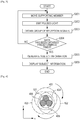
- a weight corresponding to the relative positions of the supporting member and a target position is assigned to reception signal data obtained through a plurality of times of irradiation, so as to perform reconstruction processing.
- the main controller 104 sets a target position for reconstruction, for example, a voxel (step S315).
- the set target position may be predetermined, or may be designated by a user using the input unit 103.
- the main controller 104 may set a target position on the basis of information representing the positions of the subject at individual irradiation timings. There is a probability that the position of the subject corresponding to the target position set before irradiation is changed when the subject is irradiated, and thus the target position for reconstruction may be changed in accordance with information representing the position of the subject at each irradiation timing.
- the photoacoustic apparatus may include a first measurement unit capable of measuring a position of a subject.
- a device for measuring a position of a subject by using image data obtained from a charge-coupled device (CCD) camera, a complementary metal-oxide semiconductor (CMOS) camera, or the like, or a device for measuring a position of a subject by using information representing displacement of the subject obtained by a gyro sensor or the like may be used.
- the main controller 104 obtains information representing the relative positions of the supporting member 202 and the target position when the subject is irradiated with pulsed light in step S302 (step S325).
- the main controller 104 may include a second memory that stores in advance weights corresponding to the relative positions of the supporting member 202 and the target position at individual irradiation timings.
- the main controller 104 is able to read a weight corresponding to each irradiation from the second memory, and thereby determine the weight.
- the first memory and the second memory may be constituted by a single hardware unit or different hardware units.
- the main controller 104 may receive information representing the positions of the supporting member 202 at the individual irradiation timings, the positions detected by the position sensor as a second measurement unit provided in the driving device 107.
- the second measurement unit may obtain information representing the position of the supporting member 202 by using, as a trigger, an irradiation control signal for the light irradiation unit 106 or light emitted from the light irradiation unit 106. Accordingly, even in a case where an error occurs between a preset irradiation timing or the position of the supporting member 201 and an actual measurement state, information representing the position of the supporting member 202 at the time when light is actually applied can be obtained with high accuracy.
- the main controller 104 determines, on the basis of the position information about the target position obtained in step S315 and the position information about the supporting member 202 obtained in step S325, a weight corresponding to the relative positions of the target position and the supporting member 202 (step S335).
- a voxel 501 as a target position is a voxel to be reconstructed.
- Broken lines 502 represent directional axes of the individual transducers 201.
- a point 503 is the curvature center of the supporting member 202 at the j-th irradiation.
- the curvature center 503 corresponds to a position at which the directional axes of at least some of the plurality of transducers 201 converge.
- s j represents the distance between the voxel 501 and the curvature center 503.
- the weight may increase as the distance s j decreases, and the weight may decrease as the distance s j increases.
- An average of a plurality of weights adapted to the individual transducers 201 at the time when the supporting member 202 and the voxel 501 have a certain relative positional relationship may be used as a weight assigned to the individual transducers 201.
- an average of weights adapted to individual transducers 201 used for reconstructing an image in the time domain called Universal Back Projection (UBP) described in Xu, Minghua, and Lihong V. Wang. "Universal back-projection algorithm for photoacoustic computed tomography" Physical Review E 71.1 (2005 ) may be used as a weight.
- UBP Universal Back Projection
- Equation (3) a weight w i,j corresponding to the transducer at the position represented by a position vector d i,j (the position vector of the i-th transducer at the j-th irradiation) is expressed by Equation (3).
- w i , j ⁇ S i , j r ⁇ d i , j 2 ⁇ n s 0 i , j ⁇ r ⁇ d i , j r ⁇ d i , j
- ⁇ S i,j represents the area of the transducer existing at the position represented by the position vector d i,j
- ns 0i,j represents a unit normal vector (orientation direction) with respect to the reception surface of the transducer existing at the position represented by the position vector d i,j . That is, a weight adapted to each transducer in UBP is a solid angle of each transducer with respect to a voxel.
- a weight w j to be assigned to each transducer 201 supported by the supporting member 202 at the j-th irradiation can be expressed by equation (4) by averaging weights w i,j of the individual transducers 201.
- weights adapted to the individual transducers 201 used for image reconstruction according to the related art may be averaged, and the average weight may be used.
- the average weight may be stored in the second memory, and may be read from the second memory at the time of reconstruction.
- the main controller 104 may change the weight step by step in accordance with the distance s j .
- the main controller 104 may continuously change the weight as illustrated in Fig. 7A , or may discretely change the weight as illustrated in Fig. 7B .
- the transducers 201 have directivity and are fixed toward the center of the hemisphere.
- acoustic waves generated at the vicinity of the center of the hemisphere can be received by the individual transducers 201 with high sensitivity.
- the reconstruction can be performed with higher resolution by receiving acoustic waves in the direction for covering the largest possible solid angle.
- acoustic waves from the center of the hemisphere can be received with high sensitivity at the largest solid angle, and thus the weight may be increased toward the center of the hemisphere to perform reconstruction.
- a larger weight may be assigned to a group of reception signals output from a plurality of transducers when the initial sound pressure of the acoustic waves generated at the target position is high.
- a large weight may be assigned to a group of reception signals of acoustic waves generated when the fluence of light applied to the target position is high. That is, a weight corresponding to the amount of light may be applied to data of a group of reception signals. Accordingly, a weight for a group of reception signals having a high S/N ratio can be increased.
- the S/N ratio of subject information at the target position reconstructed by using the group of weighted reception signals can also be increased. For example, a value calculated by multiplying a weight determined in accordance with the relative positions of the supporting member and the target position by the amount of light at the target position may be used as a weight.
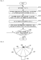
- Figs. 8A and 8B are diagrams illustrating a state of pulsed light emitted from the light exit 108 and a state where acoustic waves output from the voxel 501 reach the transducers 201. Acoustic waves may be output from a position other than the voxel 501, but the illustration thereof is omitted for convenience.
- Fig. 8A is a diagram illustrating a case where the distance s j is short. Pulsed light 601 is intensely applied to the voxel 501, and intense acoustic waves 602 are output from the voxel 501. The acoustic waves 602 enter the individual transducers 201 at almost the right angles. Thus, the individual transducers 201 obtain reception signals that largely contribute to increase the quantitativity of subject information of the voxel 501 to be obtained.
- Fig. 8B is a diagram illustrating a case where the distance s j is long. Pulsed light 603 is hardly applied to the voxel 501, and accordingly the intensity of acoustic waves 604 output from the voxel 501 is low. Further, the acoustic waves 604 enter many of the transducers 201 at an angle with respect to a perpendicular direction on the reception surface. Thus, the individual transducers 201 dominantly obtain reception signals that do not largely contribute to increase the quantitativity of subject information of the voxel 501 to be obtained.
- a group of obtained reception signals contribute more largely to increase the quantitativity of subject information of the voxel 501 as the distance s j decreases, and thus a large weight may be assigned to the group of reception signals.
- the position of the curvature center of the supporting member 202 and the position at which the directional axes of the plurality of transducers 202 converge can be estimated on the basis of the position of the supporting member 202.
- a weight may be determined with reference to the positional relationship between the supporting member 202 and a target position.
- the relative positions of the supporting member 202 and the subject at the time when light is actually applied can be determined with high accuracy.
- a weight that is suitable for an actual state at the time of irradiation and that corresponds to the relative positions of the supporting member 202 and the target position can be determined.
- steps S345 and S355 will be described.
- the position vector of a voxel to be reconstructed (target position) is represented by r
- the initial sound pressure of the voxel to be reconstructed is represented by p 0 (r)
- the number of transducers 201 is represented by N
- the number of times signal data is obtained is represented by M
- the sonic speed of acoustic waves in a propagation path is represented by c.
- a weight assigned to data of a group of reception signals at the time of the j-th irradiation is represented by w j (j is larger than or equal to 1 and smaller than or equal to M)
- the position vector of the i-th transducer at the time of the j-th irradiation is represented by d i,j
- a signal strength at time t' of data of time-series reception signals obtained by the transducer at the position represented by the position vector d i,j is represented by p(d i,j , t').
- the main controller 104 is able to calculate an initial sound pressure as subject information by using the equation expressed by Equation (5).
- Equation (5) [Math.5]
- the main controller 104 determines whether or not subject information for all the set target positons has been obtained (step S365). If subject information for all the set target positions has not been obtained, the processing returns to step S315. The step that has been performed for all the target positions need not be performed again. That is, the processing may return to the step that has not been performed for all the target positions. Equation (5) expresses only a case where one certain voxel is reconstructed. With the same processing repeatedly performed on a plurality of voxels (all the target positions), a certain region can be reconstructed.
- the main controller 104 may calculate initial sound pressures for data of groups of reception signals obtained through the first to j-th irradiations by using Equation (6), and then may combine the initial sound pressures.
- step S305 may be performed to obtain subject information every time steps S301 to S303 are performed.
- a plurality of pieces of subject information obtained in step S305 may be combined to obtain final subject information.
- the weight may be assigned after the reception signal p(d i,j , t') has been positively defined as expressed by Equation (7), as described in Xu, Minghua, and Lihong V. Wang. "Universal back-projection algorithm for photoacoustic computed tomography" Physical Review E 71.1 (2005 ).
- b(d i,j , t') represents the strength of the positively defined reception signal.
- An algorithm of positively defining the reception signal is not limited to Equation (7), and any other methods may be used.
- a weight that is based on the tendency for image quality to isotropically decrease from the curvature center of the supporting member is a weight that is based on a different tendency.
- a highly-sensitive region is not a sphere whose center is a position at which the directional axes of a plurality of transducers converge.
- the highly-sensitive region has a tendency to extend more in the region near the supporting member than in the region distant from the supporting member relative to the position at which the directional axes of the plurality of transducers converge.
- the main controller may assign a weight to a target position included in the region near the supporting member, the weight being larger than a weight assigned to a target position included in the region distant from the supporting member, relative to the position at which the directional axes of the plurality of transducers converge. That is, among target positions at the same distance from the position at which the directional axes of the plurality of transducers converge, a weight may be assigned to a target position included in the region near the supporting member, the weight being larger than a weight assigned to a target position included in the region distant from the supporting member.
- the main controller may assign the largest weight to a target position located on the probe side relative to the position at which the directional axes of the plurality of transducers converge. Further, the main controller may assign a larger weight as the distance from a certain position near the supporting member to a target position decreases, relative to the position at which the directional axes of the plurality of transducers converge. Also in these cases, a weight can be assigned on the basis of the relative positions of the supporting member and the target position.
- a uniform weight corresponding to the positional relationship between a supporting member and a target position is assigned to a group of reception signals obtained from a plurality of transducers, and accordingly subject information having high quantitativity and resolution can be obtained.
- a group of reception signals to be used for reconstructing a target position is selected from data of a plurality of groups of reception signals stored in the first memory.
- a group of reception signals not to be used for reconstruction is selected from among a plurality of groups of reception signals.
- a weight of 0 may be assigned to the group of reception signals not to be used for reconstruction, or the group of reception signals is not read at the time of reconstruction.
- signals to be used for reconstructing an image at a target position may be selected from the viewpoint described below.
- An image at a target position may be reconstructed by using reception signals output from transducers whose directional axes are oriented to the target position. Accordingly, acoustic waves generated at the target position can be received with high sensitivity, and thus the S/N ratio of the reception signals corresponding to acoustic waves generated at the target position can be increased. Thus, the S/N ratio of the image strength at the target position reconstructed by using the reception signals can be increased.
- the transducers may be arranged so as to receive many frequency components of acoustic waves generated from the target position. Accordingly, at the time of reconstructing an image, the energy corresponding to a reconstruction artifact is distributed over the entire reconstructed image, and thus local occurrence of a reconstruction artifact can be suppressed.
- the photoacoustic apparatus determines a group of reception signals to be used for obtaining subject information at a target position from among a plurality of groups of reception signals stored in the first memory in accordance with the relative positions of the supporting member and a target position. That is, the photoacoustic apparatus according to this embodiment determines a group of reception signals not to be used for obtaining subject information at the target position from among the plurality of groups of reception signals stored in the first memory in accordance with the distance between the supporting member and the target position.
- step S335 the weight according to this embodiment is determined by using Equation (8).
- w j ⁇ 1 s j ⁇ d th 0 s j > d th
- d th represents the radius of a highly-sensitive region. That is, a voxel is reconstructed without using, for calculation, a group of reception signals obtained at the time when the voxel is not included in a highly-sensitive region.
- the range of the highly-sensitive region as a threshold can be estimated by using Equation (1).
- the highly-sensitive region is not always a sphere whose center is a position at which the directional axes of the plurality of transducers 201 converge.
- the inventors have found that the highly-sensitive region may have a larger area in a region on the supporting member 202 side than in a region distant from the supporting member 202, relative to the position at which the directional axes of the plurality of transducers 201 converge.
- the main controller 104 may perform reconstruction for a target position at a further position in the direction of approaching the supporting member 202 relative to the position at which the directional axes of the plurality of transducers 201 converge, compared to the direction of becoming distant from the supporting member 202.
- the main controller 104 may perform reconstruction for only a target position at a closer position in the direction of becoming distant from the supporting member 202 relative to the position at which the directional axes of the plurality of transducers 201 converge, compared to the direction of approaching the supporting member 202.
- the main controller 104 may perform reconstruction for a target position at a position in the direction of approaching the supporting member 202, and need not perform reconstruction for a target position at a position in the direction of becoming distant from the supporting member 202, among target positions at the same distance from the position at which the directional axes of the plurality of transducers 201 converge.
- the threshold may vary depending on a direction from the position at which the directional axes of the plurality of transducers converge toward the target position.
- the reconstruction processing to which the present invention is applicable is not limited to processing performed by using the above-described equations, and other time-domain reconstruction may be applied. Also, the present invention is applicable to Fourier-domain reconstruction and model base reconstruction.
- Embodiments of the present invention can also be realized by a computer of a system or apparatus that reads out and executes computer executable instructions recorded on a storage medium (e.g., non-transitory computer-readable storage medium)to perform the functions of one or more of the above-described embodiments of the present invention, and by a method performed by the computer of the system or apparatus by, for example, reading out and executing the computer executable instructions from the storage medium to perform the functions of one or more of the above-described embodiments.
- the computer may comprise one or more of a central processing unit (CPU), micro processing unit (MPU), or other circuitry, and may include a network of separate computers or separate computer processors.
- the computer executable instructions may be provided to the computer, for example, from a network or the storage medium.
- the storage medium may include, for example, one or more of a hard disk, a random-access memory(RAM), a read only memory (ROM), a storage of distributed computing systems, an optical disk (such as a compact disc (CD), digital versatile disc (DVD), or Blu-ray Disc (BD) (registered trademark)), a flash memory device, a memory card, and the like.
Landscapes
- Health & Medical Sciences (AREA)
- Life Sciences & Earth Sciences (AREA)
- Physics & Mathematics (AREA)
- Pathology (AREA)
- General Health & Medical Sciences (AREA)
- Analytical Chemistry (AREA)
- Biochemistry (AREA)
- Chemical & Material Sciences (AREA)
- General Physics & Mathematics (AREA)
- Immunology (AREA)
- Surgery (AREA)
- Acoustics & Sound (AREA)
- Biophysics (AREA)
- Engineering & Computer Science (AREA)
- Biomedical Technology (AREA)
- Heart & Thoracic Surgery (AREA)
- Medical Informatics (AREA)
- Molecular Biology (AREA)
- Animal Behavior & Ethology (AREA)
- Public Health (AREA)
- Veterinary Medicine (AREA)
- Optics & Photonics (AREA)
- Ultra Sonic Daignosis Equipment (AREA)
Applications Claiming Priority (2)
| Application Number | Priority Date | Filing Date | Title |
|---|---|---|---|
| US201461992983P | 2014-05-14 | 2014-05-14 | |
| PCT/JP2015/002414 WO2015174085A1 (en) | 2014-05-14 | 2015-05-12 | Photoacoustic apparatus |
Publications (2)
| Publication Number | Publication Date |
|---|---|
| EP3143391A1 EP3143391A1 (en) | 2017-03-22 |
| EP3143391B1 true EP3143391B1 (en) | 2020-07-08 |
Family
ID=53276221
Family Applications (1)
| Application Number | Title | Priority Date | Filing Date |
|---|---|---|---|
| EP15726356.7A Active EP3143391B1 (en) | 2014-05-14 | 2015-05-12 | Photoacoustic apparatus |
Country Status (5)
| Country | Link |
|---|---|
| US (1) | US10495567B2 (enExample) |
| EP (1) | EP3143391B1 (enExample) |
| JP (1) | JP6545190B2 (enExample) |
| CN (1) | CN106455992B (enExample) |
| WO (1) | WO2015174085A1 (enExample) |
Families Citing this family (7)
| Publication number | Priority date | Publication date | Assignee | Title |
|---|---|---|---|---|
| CN105342567B (zh) * | 2015-11-23 | 2018-08-07 | 苏州大学 | 一种提高重建光声图像信噪比的装置和方法 |
| JP6594355B2 (ja) * | 2017-01-06 | 2019-10-23 | キヤノン株式会社 | 被検体情報処理装置および画像の表示方法 |
| JP2018126389A (ja) * | 2017-02-09 | 2018-08-16 | キヤノン株式会社 | 情報処理装置、情報処理方法、およびプログラム |
| JP6650908B2 (ja) | 2017-06-16 | 2020-02-19 | キヤノン株式会社 | 被検体情報取得装置及び被検体情報取得装置の制御方法 |
| DE102017219338B3 (de) * | 2017-10-27 | 2019-02-28 | Humboldt-Universität Zu Berlin | Photoakustik-Sensorkopf und Photoakustik-Messapparat mit verbesserter Störsignal-Unterdrückung |
| JP7118718B2 (ja) * | 2018-04-18 | 2022-08-16 | キヤノン株式会社 | 被検体情報取得装置、被検体情報処理方法、およびプログラム |
| CN114563479B (zh) * | 2022-04-20 | 2022-08-30 | 之江实验室 | 一种实时三维高分辨太赫兹光声成像方法和装置 |
Family Cites Families (32)
| Publication number | Priority date | Publication date | Assignee | Title |
|---|---|---|---|---|
| US5713356A (en) * | 1996-10-04 | 1998-02-03 | Optosonics, Inc. | Photoacoustic breast scanner |
| GB9704737D0 (en) * | 1997-03-07 | 1997-04-23 | Optel Instr Limited | Biological measurement system |
| US6694799B2 (en) * | 2002-02-22 | 2004-02-24 | Eastern Washington University | Method and apparatus for detection of particles |
| AU2003300052A1 (en) * | 2002-12-31 | 2004-08-10 | John Herbert Cafarella | Multi-sensor breast tumor detection |
| ES2431520T3 (es) * | 2003-01-25 | 2013-11-26 | Seno Medical Instruments, Inc. | Procedimiento de formación de imágenes optoacústicas de contraste elevado utilizando nanopartículas no esféricas |
| US9597024B2 (en) * | 2005-02-09 | 2017-03-21 | Medici Instruments Llc | Methods and apparatuses for noninvasive determinations of analytes |
| US20110184260A1 (en) * | 2005-02-09 | 2011-07-28 | Robinson M Ries | Methods and Apparatuses for Noninvasive Determinations of Analytes |
| US20080173093A1 (en) * | 2007-01-18 | 2008-07-24 | The Regents Of The University Of Michigan | System and method for photoacoustic tomography of joints |
| WO2009110028A1 (ja) * | 2008-03-06 | 2009-09-11 | 株式会社島津製作所 | 超音波診断装置及びプログラム |
| JP4829934B2 (ja) * | 2008-07-11 | 2011-12-07 | キヤノン株式会社 | 検査装置 |
| US9572497B2 (en) * | 2008-07-25 | 2017-02-21 | Helmholtz Zentrum Munchen Deutsches Forschungszentrum Fur Gesundheit Und Umwelt (Gmbh) | Quantitative multi-spectral opto-acoustic tomography (MSOT) of tissue biomarkers |
| JP5496098B2 (ja) * | 2008-08-27 | 2014-05-21 | キヤノン株式会社 | 被検体情報取得装置およびその制御方法 |
| EP2260754A1 (en) * | 2009-06-10 | 2010-12-15 | Universiteit Twente | Device and method for photon absorption coefficient measurement |
| JP5683213B2 (ja) * | 2009-11-17 | 2015-03-11 | キヤノン株式会社 | 画像形成装置及び画像形成方法 |
| JP5917039B2 (ja) * | 2010-09-13 | 2016-05-11 | キヤノン株式会社 | 被検体情報取得装置 |
| US20120071761A1 (en) * | 2010-09-21 | 2012-03-22 | Toshiba Medical Systems Corporation | Medical ultrasound 2-d transducer array using fresnel lens approach |
| JP5939786B2 (ja) * | 2011-02-10 | 2016-06-22 | キヤノン株式会社 | 音響波取得装置 |
| US9445786B2 (en) * | 2011-11-02 | 2016-09-20 | Seno Medical Instruments, Inc. | Interframe energy normalization in an optoacoustic imaging system |
| JP5988598B2 (ja) | 2012-01-31 | 2016-09-07 | キヤノン株式会社 | 被検体情報取得装置および被検体情報取得方法 |
| US20140155760A1 (en) * | 2012-02-15 | 2014-06-05 | Trent Daniel Ridder | Remote and local transfer of information in noninvasive hydration measurements |
| US20130210058A1 (en) * | 2012-02-15 | 2013-08-15 | Lakeland Ventures Development, Llc | System for noninvasive determination of water in tissue |
| US20140171759A1 (en) * | 2012-02-15 | 2014-06-19 | Craig William WHITE | Noninvasive determination of intravascular and exctravascular hydration using near infrared spectroscopy |
| JP2013215236A (ja) | 2012-04-04 | 2013-10-24 | Canon Inc | 被検体情報取得装置および被検体情報取得方法 |
| JP6172912B2 (ja) * | 2012-10-23 | 2017-08-02 | キヤノン株式会社 | 被検体情報取得装置および光音響プローブ |
| EP2950711A4 (en) * | 2013-01-31 | 2016-09-21 | Univ Ramot | IDENTIFICATION, DIAGNOSIS AND MONITORING OF OSTEOPOROSIS BY A PHOTOACUSTIC PROCEDURE |
| US9723995B2 (en) * | 2013-12-04 | 2017-08-08 | The Johns Hopkins University | Systems and methods for real-time tracking of photoacoustic sensing |
| US10531828B2 (en) * | 2014-01-31 | 2020-01-14 | The Johns Hopkins University | Method and system for transcranial photoacoustic imaging for guiding skull base surgeries |
| CN106455994B (zh) * | 2014-05-14 | 2019-09-03 | 佳能株式会社 | 光声装置 |
| TWI529391B (zh) * | 2015-01-22 | 2016-04-11 | 國立臺灣大學 | 利用光聲效應產生超音波之系統與成像方法 |
| US10441250B2 (en) * | 2015-10-08 | 2019-10-15 | Zmk Medical Technologies Inc. | 3D multi-parametric ultrasound imaging |
| US20170209119A1 (en) * | 2016-01-27 | 2017-07-27 | Canon Kabushiki Kaisha | Photoacoustic ultrasonic imaging apparatus |
| US20180064347A1 (en) * | 2016-09-08 | 2018-03-08 | The Penn State Research Foundation | Handheld device and multimodal contrast agent for early detection of human disease |
-
2015
- 2015-05-12 WO PCT/JP2015/002414 patent/WO2015174085A1/en not_active Ceased
- 2015-05-12 US US15/310,082 patent/US10495567B2/en not_active Expired - Fee Related
- 2015-05-12 CN CN201580025861.8A patent/CN106455992B/zh not_active Expired - Fee Related
- 2015-05-12 JP JP2016564286A patent/JP6545190B2/ja not_active Expired - Fee Related
- 2015-05-12 EP EP15726356.7A patent/EP3143391B1/en active Active
Non-Patent Citations (1)
| Title |
|---|
| None * |
Also Published As
| Publication number | Publication date |
|---|---|
| EP3143391A1 (en) | 2017-03-22 |
| US10495567B2 (en) | 2019-12-03 |
| CN106455992A (zh) | 2017-02-22 |
| US20170234790A1 (en) | 2017-08-17 |
| WO2015174085A1 (en) | 2015-11-19 |
| JP6545190B2 (ja) | 2019-07-17 |
| CN106455992B (zh) | 2019-09-10 |
| JP2017521104A (ja) | 2017-08-03 |
Similar Documents
| Publication | Publication Date | Title |
|---|---|---|
| EP3143391B1 (en) | Photoacoustic apparatus | |
| US10531798B2 (en) | Photoacoustic information acquiring apparatus and processing method | |
| US10408934B2 (en) | Object information acquiring apparatus | |
| EP3188646B1 (en) | Object information acquiring apparatus | |
| JP6472437B2 (ja) | 光音響装置、及び音響波受信装置 | |
| JP6742745B2 (ja) | 情報取得装置および表示方法 | |
| US11006929B2 (en) | Object information acquiring apparatus and signal processing method | |
| US20200085345A1 (en) | Object information acquisition apparatus and method of controlling the same | |
| US10436706B2 (en) | Information processing apparatus, information processing method, and storage medium | |
| EP3329843B1 (en) | Display control apparatus, display control method, and program | |
| US20170303792A1 (en) | Object information acquiring apparatus and object information acquiring method | |
| US20150327769A1 (en) | Photoacoustic apparatus | |
| KR20200067254A (ko) | 정보 처리장치, 정보 처리방법, 및 비일시적인 기억매체 | |
| JP6469133B2 (ja) | 処理装置、光音響装置、処理方法、およびプログラム | |
| US20200163554A1 (en) | Image generating apparatus, image generating method, and non-transitory computer-readable medium | |
| JP6942847B2 (ja) | 被検体情報取得装置および信号処理方法 | |
| JP7277212B2 (ja) | 画像処理装置、画像処理方法及びプログラム | |
| US20200305727A1 (en) | Image processing device, image processing method, and program | |
| US10172524B2 (en) | Photoacoustic apparatus | |
| WO2018101258A1 (en) | Display control apparatus, display method, and program |
Legal Events
| Date | Code | Title | Description |
|---|---|---|---|
| STAA | Information on the status of an ep patent application or granted ep patent |
Free format text: STATUS: THE INTERNATIONAL PUBLICATION HAS BEEN MADE |
|
| PUAI | Public reference made under article 153(3) epc to a published international application that has entered the european phase |
Free format text: ORIGINAL CODE: 0009012 |
|
| STAA | Information on the status of an ep patent application or granted ep patent |
Free format text: STATUS: REQUEST FOR EXAMINATION WAS MADE |
|
| 17P | Request for examination filed |
Effective date: 20161214 |
|
| AK | Designated contracting states |
Kind code of ref document: A1 Designated state(s): AL AT BE BG CH CY CZ DE DK EE ES FI FR GB GR HR HU IE IS IT LI LT LU LV MC MK MT NL NO PL PT RO RS SE SI SK SM TR |
|
| AX | Request for extension of the european patent |
Extension state: BA ME |
|
| DAV | Request for validation of the european patent (deleted) | ||
| DAX | Request for extension of the european patent (deleted) | ||
| STAA | Information on the status of an ep patent application or granted ep patent |
Free format text: STATUS: EXAMINATION IS IN PROGRESS |
|
| 17Q | First examination report despatched |
Effective date: 20180829 |
|
| GRAP | Despatch of communication of intention to grant a patent |
Free format text: ORIGINAL CODE: EPIDOSNIGR1 |
|
| STAA | Information on the status of an ep patent application or granted ep patent |
Free format text: STATUS: GRANT OF PATENT IS INTENDED |
|
| INTG | Intention to grant announced |
Effective date: 20200107 |
|
| GRAS | Grant fee paid |
Free format text: ORIGINAL CODE: EPIDOSNIGR3 |
|
| GRAA | (expected) grant |
Free format text: ORIGINAL CODE: 0009210 |
|
| STAA | Information on the status of an ep patent application or granted ep patent |
Free format text: STATUS: THE PATENT HAS BEEN GRANTED |
|
| AK | Designated contracting states |
Kind code of ref document: B1 Designated state(s): AL AT BE BG CH CY CZ DE DK EE ES FI FR GB GR HR HU IE IS IT LI LT LU LV MC MK MT NL NO PL PT RO RS SE SI SK SM TR |
|
| REG | Reference to a national code |
Ref country code: CH Ref legal event code: EP Ref country code: AT Ref legal event code: REF Ref document number: 1289007 Country of ref document: AT Kind code of ref document: T Effective date: 20200715 |
|
| REG | Reference to a national code |
Ref country code: DE Ref legal event code: R096 Ref document number: 602015055410 Country of ref document: DE |
|
| REG | Reference to a national code |
Ref country code: IE Ref legal event code: FG4D |
|
| REG | Reference to a national code |
Ref country code: LT Ref legal event code: MG4D |
|
| REG | Reference to a national code |
Ref country code: AT Ref legal event code: MK05 Ref document number: 1289007 Country of ref document: AT Kind code of ref document: T Effective date: 20200708 |
|
| REG | Reference to a national code |
Ref country code: NL Ref legal event code: MP Effective date: 20200708 |
|
| PG25 | Lapsed in a contracting state [announced via postgrant information from national office to epo] |
Ref country code: ES Free format text: LAPSE BECAUSE OF FAILURE TO SUBMIT A TRANSLATION OF THE DESCRIPTION OR TO PAY THE FEE WITHIN THE PRESCRIBED TIME-LIMIT Effective date: 20200708 Ref country code: SE Free format text: LAPSE BECAUSE OF FAILURE TO SUBMIT A TRANSLATION OF THE DESCRIPTION OR TO PAY THE FEE WITHIN THE PRESCRIBED TIME-LIMIT Effective date: 20200708 Ref country code: HR Free format text: LAPSE BECAUSE OF FAILURE TO SUBMIT A TRANSLATION OF THE DESCRIPTION OR TO PAY THE FEE WITHIN THE PRESCRIBED TIME-LIMIT Effective date: 20200708 Ref country code: PT Free format text: LAPSE BECAUSE OF FAILURE TO SUBMIT A TRANSLATION OF THE DESCRIPTION OR TO PAY THE FEE WITHIN THE PRESCRIBED TIME-LIMIT Effective date: 20201109 Ref country code: FI Free format text: LAPSE BECAUSE OF FAILURE TO SUBMIT A TRANSLATION OF THE DESCRIPTION OR TO PAY THE FEE WITHIN THE PRESCRIBED TIME-LIMIT Effective date: 20200708 Ref country code: LT Free format text: LAPSE BECAUSE OF FAILURE TO SUBMIT A TRANSLATION OF THE DESCRIPTION OR TO PAY THE FEE WITHIN THE PRESCRIBED TIME-LIMIT Effective date: 20200708 Ref country code: GR Free format text: LAPSE BECAUSE OF FAILURE TO SUBMIT A TRANSLATION OF THE DESCRIPTION OR TO PAY THE FEE WITHIN THE PRESCRIBED TIME-LIMIT Effective date: 20201009 Ref country code: BG Free format text: LAPSE BECAUSE OF FAILURE TO SUBMIT A TRANSLATION OF THE DESCRIPTION OR TO PAY THE FEE WITHIN THE PRESCRIBED TIME-LIMIT Effective date: 20201008 Ref country code: NO Free format text: LAPSE BECAUSE OF FAILURE TO SUBMIT A TRANSLATION OF THE DESCRIPTION OR TO PAY THE FEE WITHIN THE PRESCRIBED TIME-LIMIT Effective date: 20201008 Ref country code: AT Free format text: LAPSE BECAUSE OF FAILURE TO SUBMIT A TRANSLATION OF THE DESCRIPTION OR TO PAY THE FEE WITHIN THE PRESCRIBED TIME-LIMIT Effective date: 20200708 |
|
| PG25 | Lapsed in a contracting state [announced via postgrant information from national office to epo] |
Ref country code: RS Free format text: LAPSE BECAUSE OF FAILURE TO SUBMIT A TRANSLATION OF THE DESCRIPTION OR TO PAY THE FEE WITHIN THE PRESCRIBED TIME-LIMIT Effective date: 20200708 Ref country code: PL Free format text: LAPSE BECAUSE OF FAILURE TO SUBMIT A TRANSLATION OF THE DESCRIPTION OR TO PAY THE FEE WITHIN THE PRESCRIBED TIME-LIMIT Effective date: 20200708 Ref country code: LV Free format text: LAPSE BECAUSE OF FAILURE TO SUBMIT A TRANSLATION OF THE DESCRIPTION OR TO PAY THE FEE WITHIN THE PRESCRIBED TIME-LIMIT Effective date: 20200708 Ref country code: IS Free format text: LAPSE BECAUSE OF FAILURE TO SUBMIT A TRANSLATION OF THE DESCRIPTION OR TO PAY THE FEE WITHIN THE PRESCRIBED TIME-LIMIT Effective date: 20201108 |
|
| PG25 | Lapsed in a contracting state [announced via postgrant information from national office to epo] |
Ref country code: NL Free format text: LAPSE BECAUSE OF FAILURE TO SUBMIT A TRANSLATION OF THE DESCRIPTION OR TO PAY THE FEE WITHIN THE PRESCRIBED TIME-LIMIT Effective date: 20200708 |
|
| REG | Reference to a national code |
Ref country code: DE Ref legal event code: R097 Ref document number: 602015055410 Country of ref document: DE |
|
| PG25 | Lapsed in a contracting state [announced via postgrant information from national office to epo] |
Ref country code: DK Free format text: LAPSE BECAUSE OF FAILURE TO SUBMIT A TRANSLATION OF THE DESCRIPTION OR TO PAY THE FEE WITHIN THE PRESCRIBED TIME-LIMIT Effective date: 20200708 Ref country code: CZ Free format text: LAPSE BECAUSE OF FAILURE TO SUBMIT A TRANSLATION OF THE DESCRIPTION OR TO PAY THE FEE WITHIN THE PRESCRIBED TIME-LIMIT Effective date: 20200708 Ref country code: IT Free format text: LAPSE BECAUSE OF FAILURE TO SUBMIT A TRANSLATION OF THE DESCRIPTION OR TO PAY THE FEE WITHIN THE PRESCRIBED TIME-LIMIT Effective date: 20200708 Ref country code: RO Free format text: LAPSE BECAUSE OF FAILURE TO SUBMIT A TRANSLATION OF THE DESCRIPTION OR TO PAY THE FEE WITHIN THE PRESCRIBED TIME-LIMIT Effective date: 20200708 Ref country code: SM Free format text: LAPSE BECAUSE OF FAILURE TO SUBMIT A TRANSLATION OF THE DESCRIPTION OR TO PAY THE FEE WITHIN THE PRESCRIBED TIME-LIMIT Effective date: 20200708 Ref country code: EE Free format text: LAPSE BECAUSE OF FAILURE TO SUBMIT A TRANSLATION OF THE DESCRIPTION OR TO PAY THE FEE WITHIN THE PRESCRIBED TIME-LIMIT Effective date: 20200708 |
|
| PLBE | No opposition filed within time limit |
Free format text: ORIGINAL CODE: 0009261 |
|
| STAA | Information on the status of an ep patent application or granted ep patent |
Free format text: STATUS: NO OPPOSITION FILED WITHIN TIME LIMIT |
|
| PG25 | Lapsed in a contracting state [announced via postgrant information from national office to epo] |
Ref country code: AL Free format text: LAPSE BECAUSE OF FAILURE TO SUBMIT A TRANSLATION OF THE DESCRIPTION OR TO PAY THE FEE WITHIN THE PRESCRIBED TIME-LIMIT Effective date: 20200708 |
|
| 26N | No opposition filed |
Effective date: 20210409 |
|
| PG25 | Lapsed in a contracting state [announced via postgrant information from national office to epo] |
Ref country code: SK Free format text: LAPSE BECAUSE OF FAILURE TO SUBMIT A TRANSLATION OF THE DESCRIPTION OR TO PAY THE FEE WITHIN THE PRESCRIBED TIME-LIMIT Effective date: 20200708 |
|
| PGFP | Annual fee paid to national office [announced via postgrant information from national office to epo] |
Ref country code: DE Payment date: 20210421 Year of fee payment: 7 |
|
| PG25 | Lapsed in a contracting state [announced via postgrant information from national office to epo] |
Ref country code: SI Free format text: LAPSE BECAUSE OF FAILURE TO SUBMIT A TRANSLATION OF THE DESCRIPTION OR TO PAY THE FEE WITHIN THE PRESCRIBED TIME-LIMIT Effective date: 20200708 |
|
| REG | Reference to a national code |
Ref country code: CH Ref legal event code: PL |
|
| GBPC | Gb: european patent ceased through non-payment of renewal fee |
Effective date: 20210512 |
|
| PG25 | Lapsed in a contracting state [announced via postgrant information from national office to epo] |
Ref country code: CH Free format text: LAPSE BECAUSE OF NON-PAYMENT OF DUE FEES Effective date: 20210531 Ref country code: LI Free format text: LAPSE BECAUSE OF NON-PAYMENT OF DUE FEES Effective date: 20210531 Ref country code: MC Free format text: LAPSE BECAUSE OF FAILURE TO SUBMIT A TRANSLATION OF THE DESCRIPTION OR TO PAY THE FEE WITHIN THE PRESCRIBED TIME-LIMIT Effective date: 20200708 Ref country code: LU Free format text: LAPSE BECAUSE OF NON-PAYMENT OF DUE FEES Effective date: 20210512 |
|
| REG | Reference to a national code |
Ref country code: BE Ref legal event code: MM Effective date: 20210531 |
|
| PG25 | Lapsed in a contracting state [announced via postgrant information from national office to epo] |
Ref country code: IE Free format text: LAPSE BECAUSE OF NON-PAYMENT OF DUE FEES Effective date: 20210512 Ref country code: GB Free format text: LAPSE BECAUSE OF NON-PAYMENT OF DUE FEES Effective date: 20210512 |
|
| PG25 | Lapsed in a contracting state [announced via postgrant information from national office to epo] |
Ref country code: FR Free format text: LAPSE BECAUSE OF NON-PAYMENT OF DUE FEES Effective date: 20210531 |
|
| PG25 | Lapsed in a contracting state [announced via postgrant information from national office to epo] |
Ref country code: BE Free format text: LAPSE BECAUSE OF NON-PAYMENT OF DUE FEES Effective date: 20210531 |
|
| REG | Reference to a national code |
Ref country code: DE Ref legal event code: R119 Ref document number: 602015055410 Country of ref document: DE |
|
| PG25 | Lapsed in a contracting state [announced via postgrant information from national office to epo] |
Ref country code: HU Free format text: LAPSE BECAUSE OF FAILURE TO SUBMIT A TRANSLATION OF THE DESCRIPTION OR TO PAY THE FEE WITHIN THE PRESCRIBED TIME-LIMIT; INVALID AB INITIO Effective date: 20150512 Ref country code: DE Free format text: LAPSE BECAUSE OF NON-PAYMENT OF DUE FEES Effective date: 20221201 |
|
| PG25 | Lapsed in a contracting state [announced via postgrant information from national office to epo] |
Ref country code: CY Free format text: LAPSE BECAUSE OF FAILURE TO SUBMIT A TRANSLATION OF THE DESCRIPTION OR TO PAY THE FEE WITHIN THE PRESCRIBED TIME-LIMIT Effective date: 20200708 |
|
| PG25 | Lapsed in a contracting state [announced via postgrant information from national office to epo] |
Ref country code: MK Free format text: LAPSE BECAUSE OF FAILURE TO SUBMIT A TRANSLATION OF THE DESCRIPTION OR TO PAY THE FEE WITHIN THE PRESCRIBED TIME-LIMIT Effective date: 20200708 |
|
| PG25 | Lapsed in a contracting state [announced via postgrant information from national office to epo] |
Ref country code: MT Free format text: LAPSE BECAUSE OF FAILURE TO SUBMIT A TRANSLATION OF THE DESCRIPTION OR TO PAY THE FEE WITHIN THE PRESCRIBED TIME-LIMIT Effective date: 20200708 |