EP3143290B1 - Flexibles aktuatorelement mit reaktionsmerkmal - Google Patents
Flexibles aktuatorelement mit reaktionsmerkmal Download PDFInfo
- Publication number
- EP3143290B1 EP3143290B1 EP15792695.7A EP15792695A EP3143290B1 EP 3143290 B1 EP3143290 B1 EP 3143290B1 EP 15792695 A EP15792695 A EP 15792695A EP 3143290 B1 EP3143290 B1 EP 3143290B1
- Authority
- EP
- European Patent Office
- Prior art keywords
- flexible member
- sidewall
- actuator
- reaction feature
- transition area
- Prior art date
- Legal status (The legal status is an assumption and is not a legal conclusion. Google has not performed a legal analysis and makes no representation as to the accuracy of the status listed.)
- Active
Links
Images

Classifications
-
- F—MECHANICAL ENGINEERING; LIGHTING; HEATING; WEAPONS; BLASTING
- F15—FLUID-PRESSURE ACTUATORS; HYDRAULICS OR PNEUMATICS IN GENERAL
- F15B—SYSTEMS ACTING BY MEANS OF FLUIDS IN GENERAL; FLUID-PRESSURE ACTUATORS, e.g. SERVOMOTORS; DETAILS OF FLUID-PRESSURE SYSTEMS, NOT OTHERWISE PROVIDED FOR
- F15B15/00—Fluid-actuated devices for displacing a member from one position to another; Gearing associated therewith
- F15B15/08—Characterised by the construction of the motor unit
- F15B15/10—Characterised by the construction of the motor unit the motor being of diaphragm type
Definitions
- the present invention relates to actuators, and, more particularly, to actuators with flexible members.
- Pneumatic actuators utilize pressurized gas, such as air, to push against workpieces.
- Pneumatic actuators are known that include a stiff base member and a flexible member connected to the base member, with an air chamber between the flexible member and stiff base member. When the air chamber fills with pressurized air, the pressure from the air forces the flexible member away from the stiff base member and allows the surface of the flexible member to produce work on a workpiece.
- the flexible member should not be allowed to excessively expand in the radial direction due to pressurization, or else it could rupture.
- the sidewall stiffness of the flexible member can affect the flexible member's resistance to rupturing and is related to the flexible member's geometry, material properties, or a combination thereof. While a high sidewall stiffness of the flexible member better resists rupture, the high sidewall stiffness can cause the flexible member to have problems returning to a collapsed position when pressurization is removed. Similarly, if the sidewall stiffness is too high, high stresses can be developed in the flexible member which lead to durability issues.
- the present invention provides an actuator with a flexible member that has a reaction feature which governs the flexible member's sidewall movement while maintaining appropriate levels of sidewall stiffness.
- An advantage of the present invention is that it provides a reaction feature which can help return the flexible member to its collapsed position.
- reaction feature can help the sidewall resist pivoting about the transition area.
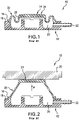
- an actuator 10 that is known in the prior art and which generally includes a stiff base 12 and a flexible member 14 connected to the stiff base 12.
- the flexible member 14 is connected to the stiff base 12 by a joint 16 formed on an edge 18 of the stiff base 12.
- a fluid chamber 20 is formed between the stiff base 12 and flexible member 14.
- An opening 22 formed in the stiff base 12 allows for fluid to enter and exit the fluid chamber 20.
- the fluid exerts a pressure, shown as arrow P in Fig. 2 , that extends the flexible member 14 away from the stiff base 12.
- the flexible member 14 is generally cylindrical in shape and has a contact surface 24 on its top that can produce work on a workpiece 26 when fluid pressure expands the flexible member 14 away from the stiff base 12.
- the flexible member 14 has a sidewall 28 that has convolutions 30 when the actuator 10 is in a collapsed state (as shown in Fig. 1 ).
- the actuator 10 is in the expanded state (as shown in Fig. 2 ), which is caused by fluid pressure P, the convolutions 30 approach the profile of the sidewall 28 as it straightens to expand its length and push the contact surface 24 against the workpiece 26.
- FIG. 3 an embodiment of an actuator 32 including a flexible member 40 formed according to the present invention is shown.
- the actuator 32 shown in Fig. 3 can be structured similarly to the actuator 10 shown in Figs. 1-2 , with flexible member 40 replacing the flexible member 14 shown in Figs. 1-2 .
- the flexible member 40 includes a sidewall 42 that has a first end 44 that connects to a stiff base member 33 of the actuator 32, which can define the actuator's bottom, and a second end 46 at the top of the sidewall 42.
- the flexible member 40 shown in Fig. 4 is in the contracted state and has convolutions 48 that arise in the sidewall 42 as a result of being contracted. These convolutions 48 can be absent in the sidewall 42 when the actuator 32 is in an expanded state.
- the flexible member 40 has a contact surface 50, which will produce work against a workpiece when the actuator 32 is in the expanded state.
- the contact surface 50 unlike the sidewall 42, will generally stay the same shape regardless of whether the actuator 32 is in an expanded or contracted state. As can be seen, the contact surface 50 can be angled to produce a top surface 51 that will be the furthest part of the contact surface 50 from the bottom of the actuator 32 and be the primary surface of contact with an actuated workpiece.
- a transition area 52 is defined between the second end 46 of the sidewall 42 and the contact surface 50. The transition area 52 can be defined between a top edge 54 of the flexible member 40 and the contact surface 50.
- a reaction feature 56 shown in greater detail in Fig. 5 , is placed on the transition area 52 and governs sidewall 42 movement and stiffness.
- the reaction feature 56 is a protrusion of material of the sidewall 42 that is shaped as a wedge that follows the perimeter of the top edge 54.
- the reaction feature 56 has a material distribution that changes across the transition area 52, such that the material distribution of the reaction feature 56 is greatest near the top edge 54 and decreases as it approaches the contact surface 50.
- the flexible member 40 expands so that the contact surface 50 and reaction feature 56 press against an actuated workpiece, with the majority of the contact between the flexible member 14 and the actuated workpiece occurring at the top surface 51.
- the portion of the sidewall 42 near the top edge 54 attempts to pivot about the transition area 52 as a result of pressure in the fluid chamber pushing on the flexible member 40, causing expansion, and the expansion being constrained about the top surface 51 by force from the actuated workpiece.
- the reaction feature 56 can come into contact with the actuated workpiece and force created by the actuated workpiece pushing on the reaction feature 56 impedes pivoting of the sidewall 42 near the top edge 54 and also helps to push the flexible member 40 back to its collapsed position when pressure in the fluid chamber is removed.
- reaction feature 56 governs sidewall 42 movement by impeding pivoting as the flexible member 40 expands and pushing the flexible member 40 back to its collapsed position as pressure is removed.
- a recess 58 can be formed on top of the flexible member 40 between the transition area 52 and top surface 50 to reduce the chance of creating a heat sink during production of the flexible member 40. As can be seen, the recess 58 can also serve as a boundary between the transition area 52 and top surface 50.
- the flexible member 40 of the present invention can be formed of any material that can sufficiently expand and collapse to actuate a workpiece, such as flexible polymers.
- the reaction feature 56 is an integral part of the sidewall 42.
- the reaction feature 56 can be continuous along its length or be segmented to alter the force distribution that is applied to the transition area 52.
- the reaction feature 56 does not need to be placed on the entire transition area 52 between the sidewall 42 and the contact surface 50, but can be placed on sections of the transition area 52 where pivoting about the transition area 52 is likely to occur and/or collapsing of the flexible member 40 is hindered.
- the reaction feature 56 can be made of the same material as the sidewall 42 or different materials that can sufficiently apply force to collapse the flexible member 40 and/or hinder pivoting about the transition area 52.
Landscapes
- Engineering & Computer Science (AREA)
- Physics & Mathematics (AREA)
- Fluid Mechanics (AREA)
- Mechanical Engineering (AREA)
- General Engineering & Computer Science (AREA)
- Actuator (AREA)
Claims (5)
- Aktuator (32), umfassend:eine Basis (33); undein flexibles Element (40) mit einer Seitenwand (42) und einer Kontaktfläche (50), wobei ein Bereich zwischen der Seitenwand (42) und der Kontaktfläche (50) einen Übergangsbereich (52) definiert, wobei das flexible Element (40) an einem ersten Ende (44) der Seitenwand (42) mit der Basis (33) verbunden ist, wobei das flexible Element (40) und die Basis (3) eine Fluidkammer zwischen sich definieren,dadurch gekennzeichnet, dassein Reaktionsmerkmal (56) am Übergangsbereich (52) angeordnet ist, wobei das Reaktionsmerkmal (56) in Form eines Materialvorsprungs der Seitenwand (42) vorliegt, der als ein Keil (56) mit einer Materialverteilung über den Übergangsbereich (52) hinweg geformt ist, die in einem Bereich angrenzend an ein zweites Ende (46) der Seitenwand (42) höher als in einem an die Kontaktfläche (50) angrenzenden Bereich ist, wobei das Reaktionsmerkmal (56) einem Umfang einer Oberkante (54) des flexiblen Elements (40) folgt und dazu konfiguriert ist, die Bewegung der Seitenwand (42) zu regulieren, um die Seitenwand (42) daran zu hindern, um den Übergangsbereich (52) zu schwenken; undwobei das flexible Element (40) eine Aussparung (58) aufweist, die zwischen dem Reaktionsmerkmal (56) und der Kontaktfläche (50) gebildet ist.
- Aktuator (32) nach Anspruch 1, wobei das Reaktionsmerkmal (56) eins von durchgehend und segmentiert ist.
- Aktuator (32) nach Anspruch 1 oder Anspruch 2, wobei die Aussparung (58) eine Grenze zwischen dem Übergangsbereich (52) und der Kontaktfläche (50) definiert.
- Aktuator (32) nach einem der Ansprüche 1 bis 3, wobei die Basis ein steifes Basiselement (33) ist, das einen Boden des Aktuators (32) definiert;
und wobei das flexible Element (40) dazu konfiguriert ist, sich auszudehnen, wenn die Fluidkammer mit Fluid gefüllt wird. - Aktuator (32) nach Anspruch 4,
wobei, wenn das flexible Element (40) sich unter Druck ausdehnt und ein Abschnitt der Seitenwand (42) nahe der Oberkante (54) danach strebt, um den Übergangsbereich (52) zu schwenken, das Reaktionsmerkmal (56) dazu konfiguriert ist, mit einem betätigten Werkstück in Kontakt zu gelangen, derart, dass eine Kraft, die durch das betätigte Werkstück ausgeübt wird und auf das Reaktionsmerkmal (56) einwirkt, den Abschnitt der Seitenwand (42) nahe der Oberkante (54) daran hindert, zu schwenken, und Druck auf das flexible Element (40) ausübt, sodass es kollabiert.
Applications Claiming Priority (2)
| Application Number | Priority Date | Filing Date | Title |
|---|---|---|---|
| US201461992610P | 2014-05-13 | 2014-05-13 | |
| PCT/US2015/030486 WO2015175606A1 (en) | 2014-05-13 | 2015-05-13 | Actuator flexible member with reaction feature |
Publications (3)
| Publication Number | Publication Date |
|---|---|
| EP3143290A1 EP3143290A1 (de) | 2017-03-22 |
| EP3143290A4 EP3143290A4 (de) | 2018-02-07 |
| EP3143290B1 true EP3143290B1 (de) | 2022-03-30 |
Family
ID=54480580
Family Applications (1)
| Application Number | Title | Priority Date | Filing Date |
|---|---|---|---|
| EP15792695.7A Active EP3143290B1 (de) | 2014-05-13 | 2015-05-13 | Flexibles aktuatorelement mit reaktionsmerkmal |
Country Status (5)
| Country | Link |
|---|---|
| US (1) | US10190606B2 (de) |
| EP (1) | EP3143290B1 (de) |
| CN (1) | CN106471263B (de) |
| AU (1) | AU2015259249B2 (de) |
| WO (1) | WO2015175606A1 (de) |
Families Citing this family (3)
| Publication number | Priority date | Publication date | Assignee | Title |
|---|---|---|---|---|
| CN205586102U (zh) * | 2014-12-01 | 2016-09-21 | 洁碧有限公司 | 防水无线口腔冲洗器 |
| US10731723B2 (en) * | 2016-12-29 | 2020-08-04 | Firestone Industrial Products Company, Llc | Pneumatic actuator assemblies as well as conveyor assemblies and conveying systems including same |
| US12286983B2 (en) * | 2021-03-19 | 2025-04-29 | Board Of Regents, The University Of Texas System | Corrugated diaphragm actuator |
Family Cites Families (17)
| Publication number | Priority date | Publication date | Assignee | Title |
|---|---|---|---|---|
| US2413287A (en) * | 1944-09-29 | 1946-12-31 | Westinghouse Air Brake Co | Fluid operable control device |
| US2697449A (en) * | 1948-12-14 | 1954-12-21 | Ernest J Svenson | Accumulator structure |
| US3319532A (en) * | 1963-08-12 | 1967-05-16 | Robertshaw Controls Co | Bellows actuator |
| US3327322A (en) * | 1964-07-27 | 1967-06-27 | Trw Inc | Artificial heart powered by a fluid pressure pump means simulating the action of the human heart |
| US3534500A (en) * | 1968-12-18 | 1970-10-20 | Raymond H Boehm | Hydraulic power unit for an automatic door opener |
| US3565398A (en) * | 1968-12-23 | 1971-02-23 | Goodrich Co B F | Pneumatic bag jack |
| US4687189A (en) * | 1985-01-26 | 1987-08-18 | Kurt Stoll | Short stroke actuator |
| US4864918A (en) * | 1986-11-07 | 1989-09-12 | The Gates Rubber Company | Thermoplastic diaphragm |
| US4905575A (en) * | 1988-10-20 | 1990-03-06 | Rosemount Inc. | Solid state differential pressure sensor with overpressure stop and free edge construction |
| US5064165A (en) * | 1989-04-07 | 1991-11-12 | Ic Sensors, Inc. | Semiconductor transducer or actuator utilizing corrugated supports |
| DE4121745A1 (de) | 1991-07-01 | 1993-01-07 | Wolf Woco & Co Franz J | Membranarbeitselement |
| US5907992A (en) * | 1997-06-06 | 1999-06-01 | Westinghouse Air Brake Company | Abrasion resistant diaphragm |
| US6398266B1 (en) * | 1999-09-22 | 2002-06-04 | Ballard Medical Products | Collapse resistant popoid connector |
| US6612223B2 (en) * | 2002-01-31 | 2003-09-02 | Bfs Diversified Products, Llc | Pneumatic actuator |
| JP4039877B2 (ja) * | 2002-03-29 | 2008-01-30 | 大瀧ジャッキ株式会社 | 扁平ジャッキ |
| CN101349294A (zh) * | 2004-07-15 | 2009-01-21 | 卢才美 | 油压或水液压的提升液压缸 |
| JP2009248709A (ja) * | 2008-04-04 | 2009-10-29 | Kawasaki Kogyo Kk | 自動車用エアージャッキ |
-
2015
- 2015-05-13 EP EP15792695.7A patent/EP3143290B1/de active Active
- 2015-05-13 WO PCT/US2015/030486 patent/WO2015175606A1/en not_active Ceased
- 2015-05-13 CN CN201580024178.2A patent/CN106471263B/zh not_active Expired - Fee Related
- 2015-05-13 AU AU2015259249A patent/AU2015259249B2/en not_active Ceased
-
2016
- 2016-11-08 US US15/346,055 patent/US10190606B2/en active Active
Also Published As
| Publication number | Publication date |
|---|---|
| CN106471263A (zh) | 2017-03-01 |
| US20170058919A1 (en) | 2017-03-02 |
| US10190606B2 (en) | 2019-01-29 |
| EP3143290A4 (de) | 2018-02-07 |
| WO2015175606A1 (en) | 2015-11-19 |
| EP3143290A1 (de) | 2017-03-22 |
| CN106471263B (zh) | 2018-10-16 |
| AU2015259249A1 (en) | 2016-11-24 |
| AU2015259249B2 (en) | 2018-07-12 |
Similar Documents
| Publication | Publication Date | Title |
|---|---|---|
| JP6215542B2 (ja) | 過移動用安全装置を備えるガスシリンダアクチュエータ | |
| EP3143290B1 (de) | Flexibles aktuatorelement mit reaktionsmerkmal | |
| EP2406520B1 (de) | Gaszylinderaktuator mit überhubsicherheitsvorrichtung | |
| EP3695093B1 (de) | Anordnung einer dichtung mit grossem abstand (lgs) | |
| JP4597372B2 (ja) | 圧力制御吸収を備えた流体容積体 | |
| US20120047979A1 (en) | Hydroforming die assembly and method for deforming a tube | |
| JP5201722B2 (ja) | 金属ベローズ式アキュムレータ | |
| CN108457927B (zh) | 具有用于活塞杆的不受控返回的安全设备的气缸致动器 | |
| EP4360843B1 (de) | Reifenformwerkzeug und reifenherstellungsverfahren | |
| WO2014186561A1 (en) | Locking mechanism for pedestrian hood lifters | |
| US6612223B2 (en) | Pneumatic actuator | |
| WO2014186591A1 (en) | Locking mechanism for pedestrian hood lifters | |
| US20040089148A1 (en) | Method and device at a piston-cylinder device | |
| CN107542721A (zh) | 具有安全装置的气缸致动器 | |
| JP7236456B2 (ja) | パイプの端部を拡大および成形するためのデバイス、ならびにこのデバイスと共に使用するための引き抜き部材 | |
| JP2006122943A (ja) | 液圧成形用ノズルおよび液圧成形装置 | |
| JP2005512849A (ja) | 変形可能な管状プラスティック容器のヘッド部品を形成する成形型 | |
| JP6804953B2 (ja) | タイヤ加硫成型金型及び空気入りタイヤの製造方法 | |
| EP3252318B1 (de) | Hydraulischer akkumulator | |
| JP6917705B2 (ja) | 過行程安全装置付きガスシリンダアクチュエータ | |
| JP2008062279A (ja) | リブを備えた缶体の成形方法 | |
| JPH0639493A (ja) | 成形装置 | |
| JP4443328B2 (ja) | ピストン | |
| JP6651343B2 (ja) | 加硫成型金型のベントプラグ及び加硫成型金型 | |
| JP2022067633A (ja) | オーバートラベル安全装置を有するガス充填シリンダ |
Legal Events
| Date | Code | Title | Description |
|---|---|---|---|
| STAA | Information on the status of an ep patent application or granted ep patent |
Free format text: STATUS: THE INTERNATIONAL PUBLICATION HAS BEEN MADE |
|
| PUAI | Public reference made under article 153(3) epc to a published international application that has entered the european phase |
Free format text: ORIGINAL CODE: 0009012 |
|
| STAA | Information on the status of an ep patent application or granted ep patent |
Free format text: STATUS: REQUEST FOR EXAMINATION WAS MADE |
|
| 17P | Request for examination filed |
Effective date: 20161103 |
|
| AK | Designated contracting states |
Kind code of ref document: A1 Designated state(s): AL AT BE BG CH CY CZ DE DK EE ES FI FR GB GR HR HU IE IS IT LI LT LU LV MC MK MT NL NO PL PT RO RS SE SI SK SM TR |
|
| AX | Request for extension of the european patent |
Extension state: BA ME |
|
| DAV | Request for validation of the european patent (deleted) | ||
| DAX | Request for extension of the european patent (deleted) | ||
| REG | Reference to a national code |
Ref country code: DE Ref legal event code: R079 Ref document number: 602015077885 Country of ref document: DE Free format text: PREVIOUS MAIN CLASS: F15B0015020000 Ipc: F15B0015100000 |
|
| A4 | Supplementary search report drawn up and despatched |
Effective date: 20180108 |
|
| RIC1 | Information provided on ipc code assigned before grant |
Ipc: F15B 15/10 20060101AFI20180102BHEP |
|
| RAP1 | Party data changed (applicant data changed or rights of an application transferred) |
Owner name: FIRESTONE INDUSTRIAL PRODUCTS COMPANY, LLC |
|
| STAA | Information on the status of an ep patent application or granted ep patent |
Free format text: STATUS: EXAMINATION IS IN PROGRESS |
|
| 17Q | First examination report despatched |
Effective date: 20210430 |
|
| GRAP | Despatch of communication of intention to grant a patent |
Free format text: ORIGINAL CODE: EPIDOSNIGR1 |
|
| STAA | Information on the status of an ep patent application or granted ep patent |
Free format text: STATUS: GRANT OF PATENT IS INTENDED |
|
| INTG | Intention to grant announced |
Effective date: 20211104 |
|
| GRAS | Grant fee paid |
Free format text: ORIGINAL CODE: EPIDOSNIGR3 |
|
| GRAA | (expected) grant |
Free format text: ORIGINAL CODE: 0009210 |
|
| STAA | Information on the status of an ep patent application or granted ep patent |
Free format text: STATUS: THE PATENT HAS BEEN GRANTED |
|
| AK | Designated contracting states |
Kind code of ref document: B1 Designated state(s): AL AT BE BG CH CY CZ DE DK EE ES FI FR GB GR HR HU IE IS IT LI LT LU LV MC MK MT NL NO PL PT RO RS SE SI SK SM TR |
|
| REG | Reference to a national code |
Ref country code: GB Ref legal event code: FG4D |
|
| REG | Reference to a national code |
Ref country code: CH Ref legal event code: EP |
|
| REG | Reference to a national code |
Ref country code: DE Ref legal event code: R096 Ref document number: 602015077885 Country of ref document: DE |
|
| REG | Reference to a national code |
Ref country code: AT Ref legal event code: REF Ref document number: 1479440 Country of ref document: AT Kind code of ref document: T Effective date: 20220415 |
|
| REG | Reference to a national code |
Ref country code: IE Ref legal event code: FG4D |
|
| REG | Reference to a national code |
Ref country code: LT Ref legal event code: MG9D |
|
| PG25 | Lapsed in a contracting state [announced via postgrant information from national office to epo] |
Ref country code: SE Free format text: LAPSE BECAUSE OF FAILURE TO SUBMIT A TRANSLATION OF THE DESCRIPTION OR TO PAY THE FEE WITHIN THE PRESCRIBED TIME-LIMIT Effective date: 20220330 Ref country code: RS Free format text: LAPSE BECAUSE OF FAILURE TO SUBMIT A TRANSLATION OF THE DESCRIPTION OR TO PAY THE FEE WITHIN THE PRESCRIBED TIME-LIMIT Effective date: 20220330 Ref country code: NO Free format text: LAPSE BECAUSE OF FAILURE TO SUBMIT A TRANSLATION OF THE DESCRIPTION OR TO PAY THE FEE WITHIN THE PRESCRIBED TIME-LIMIT Effective date: 20220630 Ref country code: LT Free format text: LAPSE BECAUSE OF FAILURE TO SUBMIT A TRANSLATION OF THE DESCRIPTION OR TO PAY THE FEE WITHIN THE PRESCRIBED TIME-LIMIT Effective date: 20220330 Ref country code: HR Free format text: LAPSE BECAUSE OF FAILURE TO SUBMIT A TRANSLATION OF THE DESCRIPTION OR TO PAY THE FEE WITHIN THE PRESCRIBED TIME-LIMIT Effective date: 20220330 Ref country code: BG Free format text: LAPSE BECAUSE OF FAILURE TO SUBMIT A TRANSLATION OF THE DESCRIPTION OR TO PAY THE FEE WITHIN THE PRESCRIBED TIME-LIMIT Effective date: 20220630 |
|
| REG | Reference to a national code |
Ref country code: NL Ref legal event code: MP Effective date: 20220330 |
|
| REG | Reference to a national code |
Ref country code: AT Ref legal event code: MK05 Ref document number: 1479440 Country of ref document: AT Kind code of ref document: T Effective date: 20220330 |
|
| PG25 | Lapsed in a contracting state [announced via postgrant information from national office to epo] |
Ref country code: LV Free format text: LAPSE BECAUSE OF FAILURE TO SUBMIT A TRANSLATION OF THE DESCRIPTION OR TO PAY THE FEE WITHIN THE PRESCRIBED TIME-LIMIT Effective date: 20220330 Ref country code: GR Free format text: LAPSE BECAUSE OF FAILURE TO SUBMIT A TRANSLATION OF THE DESCRIPTION OR TO PAY THE FEE WITHIN THE PRESCRIBED TIME-LIMIT Effective date: 20220701 Ref country code: FI Free format text: LAPSE BECAUSE OF FAILURE TO SUBMIT A TRANSLATION OF THE DESCRIPTION OR TO PAY THE FEE WITHIN THE PRESCRIBED TIME-LIMIT Effective date: 20220330 |
|
| PG25 | Lapsed in a contracting state [announced via postgrant information from national office to epo] |
Ref country code: NL Free format text: LAPSE BECAUSE OF FAILURE TO SUBMIT A TRANSLATION OF THE DESCRIPTION OR TO PAY THE FEE WITHIN THE PRESCRIBED TIME-LIMIT Effective date: 20220330 |
|
| PG25 | Lapsed in a contracting state [announced via postgrant information from national office to epo] |
Ref country code: SM Free format text: LAPSE BECAUSE OF FAILURE TO SUBMIT A TRANSLATION OF THE DESCRIPTION OR TO PAY THE FEE WITHIN THE PRESCRIBED TIME-LIMIT Effective date: 20220330 Ref country code: SK Free format text: LAPSE BECAUSE OF FAILURE TO SUBMIT A TRANSLATION OF THE DESCRIPTION OR TO PAY THE FEE WITHIN THE PRESCRIBED TIME-LIMIT Effective date: 20220330 Ref country code: RO Free format text: LAPSE BECAUSE OF FAILURE TO SUBMIT A TRANSLATION OF THE DESCRIPTION OR TO PAY THE FEE WITHIN THE PRESCRIBED TIME-LIMIT Effective date: 20220330 Ref country code: PT Free format text: LAPSE BECAUSE OF FAILURE TO SUBMIT A TRANSLATION OF THE DESCRIPTION OR TO PAY THE FEE WITHIN THE PRESCRIBED TIME-LIMIT Effective date: 20220801 Ref country code: ES Free format text: LAPSE BECAUSE OF FAILURE TO SUBMIT A TRANSLATION OF THE DESCRIPTION OR TO PAY THE FEE WITHIN THE PRESCRIBED TIME-LIMIT Effective date: 20220330 Ref country code: EE Free format text: LAPSE BECAUSE OF FAILURE TO SUBMIT A TRANSLATION OF THE DESCRIPTION OR TO PAY THE FEE WITHIN THE PRESCRIBED TIME-LIMIT Effective date: 20220330 Ref country code: CZ Free format text: LAPSE BECAUSE OF FAILURE TO SUBMIT A TRANSLATION OF THE DESCRIPTION OR TO PAY THE FEE WITHIN THE PRESCRIBED TIME-LIMIT Effective date: 20220330 Ref country code: AT Free format text: LAPSE BECAUSE OF FAILURE TO SUBMIT A TRANSLATION OF THE DESCRIPTION OR TO PAY THE FEE WITHIN THE PRESCRIBED TIME-LIMIT Effective date: 20220330 |
|
| PG25 | Lapsed in a contracting state [announced via postgrant information from national office to epo] |
Ref country code: PL Free format text: LAPSE BECAUSE OF FAILURE TO SUBMIT A TRANSLATION OF THE DESCRIPTION OR TO PAY THE FEE WITHIN THE PRESCRIBED TIME-LIMIT Effective date: 20220330 Ref country code: IS Free format text: LAPSE BECAUSE OF FAILURE TO SUBMIT A TRANSLATION OF THE DESCRIPTION OR TO PAY THE FEE WITHIN THE PRESCRIBED TIME-LIMIT Effective date: 20220730 Ref country code: AL Free format text: LAPSE BECAUSE OF FAILURE TO SUBMIT A TRANSLATION OF THE DESCRIPTION OR TO PAY THE FEE WITHIN THE PRESCRIBED TIME-LIMIT Effective date: 20220330 |
|
| REG | Reference to a national code |
Ref country code: CH Ref legal event code: PL |
|
| REG | Reference to a national code |
Ref country code: DE Ref legal event code: R097 Ref document number: 602015077885 Country of ref document: DE |
|
| REG | Reference to a national code |
Ref country code: BE Ref legal event code: MM Effective date: 20220531 |
|
| PG25 | Lapsed in a contracting state [announced via postgrant information from national office to epo] |
Ref country code: MC Free format text: LAPSE BECAUSE OF FAILURE TO SUBMIT A TRANSLATION OF THE DESCRIPTION OR TO PAY THE FEE WITHIN THE PRESCRIBED TIME-LIMIT Effective date: 20220330 Ref country code: LU Free format text: LAPSE BECAUSE OF NON-PAYMENT OF DUE FEES Effective date: 20220513 Ref country code: LI Free format text: LAPSE BECAUSE OF NON-PAYMENT OF DUE FEES Effective date: 20220531 Ref country code: DK Free format text: LAPSE BECAUSE OF FAILURE TO SUBMIT A TRANSLATION OF THE DESCRIPTION OR TO PAY THE FEE WITHIN THE PRESCRIBED TIME-LIMIT Effective date: 20220330 Ref country code: CH Free format text: LAPSE BECAUSE OF NON-PAYMENT OF DUE FEES Effective date: 20220531 |
|
| PLBE | No opposition filed within time limit |
Free format text: ORIGINAL CODE: 0009261 |
|
| STAA | Information on the status of an ep patent application or granted ep patent |
Free format text: STATUS: NO OPPOSITION FILED WITHIN TIME LIMIT |
|
| GBPC | Gb: european patent ceased through non-payment of renewal fee |
Effective date: 20220630 |
|
| 26N | No opposition filed |
Effective date: 20230103 |
|
| PG25 | Lapsed in a contracting state [announced via postgrant information from national office to epo] |
Ref country code: IE Free format text: LAPSE BECAUSE OF NON-PAYMENT OF DUE FEES Effective date: 20220513 Ref country code: FR Free format text: LAPSE BECAUSE OF NON-PAYMENT OF DUE FEES Effective date: 20220530 |
|
| PG25 | Lapsed in a contracting state [announced via postgrant information from national office to epo] |
Ref country code: SI Free format text: LAPSE BECAUSE OF FAILURE TO SUBMIT A TRANSLATION OF THE DESCRIPTION OR TO PAY THE FEE WITHIN THE PRESCRIBED TIME-LIMIT Effective date: 20220330 Ref country code: GB Free format text: LAPSE BECAUSE OF NON-PAYMENT OF DUE FEES Effective date: 20220630 Ref country code: BE Free format text: LAPSE BECAUSE OF NON-PAYMENT OF DUE FEES Effective date: 20220531 |
|
| P01 | Opt-out of the competence of the unified patent court (upc) registered |
Effective date: 20230524 |
|
| PG25 | Lapsed in a contracting state [announced via postgrant information from national office to epo] |
Ref country code: IT Free format text: LAPSE BECAUSE OF FAILURE TO SUBMIT A TRANSLATION OF THE DESCRIPTION OR TO PAY THE FEE WITHIN THE PRESCRIBED TIME-LIMIT Effective date: 20220330 |
|
| PG25 | Lapsed in a contracting state [announced via postgrant information from national office to epo] |
Ref country code: HU Free format text: LAPSE BECAUSE OF FAILURE TO SUBMIT A TRANSLATION OF THE DESCRIPTION OR TO PAY THE FEE WITHIN THE PRESCRIBED TIME-LIMIT; INVALID AB INITIO Effective date: 20150513 |
|
| PG25 | Lapsed in a contracting state [announced via postgrant information from national office to epo] |
Ref country code: MK Free format text: LAPSE BECAUSE OF FAILURE TO SUBMIT A TRANSLATION OF THE DESCRIPTION OR TO PAY THE FEE WITHIN THE PRESCRIBED TIME-LIMIT Effective date: 20220330 Ref country code: CY Free format text: LAPSE BECAUSE OF FAILURE TO SUBMIT A TRANSLATION OF THE DESCRIPTION OR TO PAY THE FEE WITHIN THE PRESCRIBED TIME-LIMIT Effective date: 20220330 |
|
| PG25 | Lapsed in a contracting state [announced via postgrant information from national office to epo] |
Ref country code: MT Free format text: LAPSE BECAUSE OF FAILURE TO SUBMIT A TRANSLATION OF THE DESCRIPTION OR TO PAY THE FEE WITHIN THE PRESCRIBED TIME-LIMIT Effective date: 20220330 |
|
| PGFP | Annual fee paid to national office [announced via postgrant information from national office to epo] |
Ref country code: DE Payment date: 20250423 Year of fee payment: 11 |
|
| PG25 | Lapsed in a contracting state [announced via postgrant information from national office to epo] |
Ref country code: TR Free format text: LAPSE BECAUSE OF FAILURE TO SUBMIT A TRANSLATION OF THE DESCRIPTION OR TO PAY THE FEE WITHIN THE PRESCRIBED TIME-LIMIT Effective date: 20220330 |