EP3142904B1 - Windscreen wiper device - Google Patents
Windscreen wiper device Download PDFInfo
- Publication number
- EP3142904B1 EP3142904B1 EP15724901.2A EP15724901A EP3142904B1 EP 3142904 B1 EP3142904 B1 EP 3142904B1 EP 15724901 A EP15724901 A EP 15724901A EP 3142904 B1 EP3142904 B1 EP 3142904B1
- Authority
- EP
- European Patent Office
- Prior art keywords
- main body
- body portion
- pair
- set forth
- wiper device
- Prior art date
- Legal status (The legal status is an assumption and is not a legal conclusion. Google has not performed a legal analysis and makes no representation as to the accuracy of the status listed.)
- Not-in-force
Links
Images


Classifications
-
- B—PERFORMING OPERATIONS; TRANSPORTING
- B60—VEHICLES IN GENERAL
- B60S—SERVICING, CLEANING, REPAIRING, SUPPORTING, LIFTING, OR MANOEUVRING OF VEHICLES, NOT OTHERWISE PROVIDED FOR
- B60S1/00—Cleaning of vehicles
- B60S1/02—Cleaning windscreens, windows or optical devices
- B60S1/04—Wipers or the like, e.g. scrapers
- B60S1/32—Wipers or the like, e.g. scrapers characterised by constructional features of wiper blade arms or blades
- B60S1/40—Connections between blades and arms
- B60S1/4003—Multi-purpose connections for two or more kinds of arm ends
-
- B—PERFORMING OPERATIONS; TRANSPORTING
- B60—VEHICLES IN GENERAL
- B60S—SERVICING, CLEANING, REPAIRING, SUPPORTING, LIFTING, OR MANOEUVRING OF VEHICLES, NOT OTHERWISE PROVIDED FOR
- B60S1/00—Cleaning of vehicles
- B60S1/02—Cleaning windscreens, windows or optical devices
- B60S1/04—Wipers or the like, e.g. scrapers
- B60S1/32—Wipers or the like, e.g. scrapers characterised by constructional features of wiper blade arms or blades
- B60S1/38—Wiper blades
- B60S1/3848—Flat-type wiper blade, i.e. without harness
- B60S1/3849—Connectors therefor; Connection to wiper arm; Attached to blade
- B60S1/3863—Connectors having a spoiler
-
- B—PERFORMING OPERATIONS; TRANSPORTING
- B60—VEHICLES IN GENERAL
- B60S—SERVICING, CLEANING, REPAIRING, SUPPORTING, LIFTING, OR MANOEUVRING OF VEHICLES, NOT OTHERWISE PROVIDED FOR
- B60S1/00—Cleaning of vehicles
- B60S1/02—Cleaning windscreens, windows or optical devices
- B60S1/04—Wipers or the like, e.g. scrapers
- B60S1/32—Wipers or the like, e.g. scrapers characterised by constructional features of wiper blade arms or blades
- B60S1/38—Wiper blades
- B60S1/3848—Flat-type wiper blade, i.e. without harness
- B60S1/3849—Connectors therefor; Connection to wiper arm; Attached to blade
- B60S1/3865—Connectors having an integral pivot pin for connection with the wiper arm
- B60S1/3868—Connectors having an integral pivot pin for connection with the wiper arm pin formed on the exterior of side walls
-
- B—PERFORMING OPERATIONS; TRANSPORTING
- B60—VEHICLES IN GENERAL
- B60S—SERVICING, CLEANING, REPAIRING, SUPPORTING, LIFTING, OR MANOEUVRING OF VEHICLES, NOT OTHERWISE PROVIDED FOR
- B60S1/00—Cleaning of vehicles
- B60S1/02—Cleaning windscreens, windows or optical devices
- B60S1/04—Wipers or the like, e.g. scrapers
- B60S1/32—Wipers or the like, e.g. scrapers characterised by constructional features of wiper blade arms or blades
- B60S1/40—Connections between blades and arms
- B60S1/4038—Connections between blades and arms for arms provided with a channel-shaped end
- B60S1/4045—Connections between blades and arms for arms provided with a channel-shaped end comprising a detachable intermediate element mounted on the channel-shaped end
- B60S1/4048—Connections between blades and arms for arms provided with a channel-shaped end comprising a detachable intermediate element mounted on the channel-shaped end the element being provided with retention means co-operating with the channel-shaped end of the arm
-
- B—PERFORMING OPERATIONS; TRANSPORTING
- B60—VEHICLES IN GENERAL
- B60S—SERVICING, CLEANING, REPAIRING, SUPPORTING, LIFTING, OR MANOEUVRING OF VEHICLES, NOT OTHERWISE PROVIDED FOR
- B60S1/00—Cleaning of vehicles
- B60S1/02—Cleaning windscreens, windows or optical devices
- B60S1/04—Wipers or the like, e.g. scrapers
- B60S1/32—Wipers or the like, e.g. scrapers characterised by constructional features of wiper blade arms or blades
- B60S1/40—Connections between blades and arms
- B60S1/4067—Connections between blades and arms for arms provided with a side pin
-
- B—PERFORMING OPERATIONS; TRANSPORTING
- B60—VEHICLES IN GENERAL
- B60S—SERVICING, CLEANING, REPAIRING, SUPPORTING, LIFTING, OR MANOEUVRING OF VEHICLES, NOT OTHERWISE PROVIDED FOR
- B60S1/00—Cleaning of vehicles
- B60S1/02—Cleaning windscreens, windows or optical devices
- B60S1/04—Wipers or the like, e.g. scrapers
- B60S1/32—Wipers or the like, e.g. scrapers characterised by constructional features of wiper blade arms or blades
- B60S1/40—Connections between blades and arms
- B60S1/4038—Connections between blades and arms for arms provided with a channel-shaped end
- B60S1/4045—Connections between blades and arms for arms provided with a channel-shaped end comprising a detachable intermediate element mounted on the channel-shaped end
- B60S1/4048—Connections between blades and arms for arms provided with a channel-shaped end comprising a detachable intermediate element mounted on the channel-shaped end the element being provided with retention means co-operating with the channel-shaped end of the arm
- B60S2001/4051—Connections between blades and arms for arms provided with a channel-shaped end comprising a detachable intermediate element mounted on the channel-shaped end the element being provided with retention means co-operating with the channel-shaped end of the arm the intermediate element engaging the side walls of the arm
-
- B—PERFORMING OPERATIONS; TRANSPORTING
- B60—VEHICLES IN GENERAL
- B60S—SERVICING, CLEANING, REPAIRING, SUPPORTING, LIFTING, OR MANOEUVRING OF VEHICLES, NOT OTHERWISE PROVIDED FOR
- B60S1/00—Cleaning of vehicles
- B60S1/02—Cleaning windscreens, windows or optical devices
- B60S1/04—Wipers or the like, e.g. scrapers
- B60S1/32—Wipers or the like, e.g. scrapers characterised by constructional features of wiper blade arms or blades
- B60S1/40—Connections between blades and arms
- B60S1/4038—Connections between blades and arms for arms provided with a channel-shaped end
- B60S1/4045—Connections between blades and arms for arms provided with a channel-shaped end comprising a detachable intermediate element mounted on the channel-shaped end
- B60S1/4048—Connections between blades and arms for arms provided with a channel-shaped end comprising a detachable intermediate element mounted on the channel-shaped end the element being provided with retention means co-operating with the channel-shaped end of the arm
- B60S2001/4054—Connections between blades and arms for arms provided with a channel-shaped end comprising a detachable intermediate element mounted on the channel-shaped end the element being provided with retention means co-operating with the channel-shaped end of the arm the intermediate element engaging the back part of the arm
Definitions
- the present invention is related to windscreen wiper devices, or wiper blade assemblies, and more precisely, to connector assemblies for connecting wiper blade assemblies to different types of wiper arms.
- Passenger vehicles may have any one of a range of different styles of oscillating wiper arms including, for example, various sizes of hook-style wiper arms, pin-style wiper arms, bayonet-style wiper arms and rock lock-style wiper arms.
- Some of the most common styles of wiper arms are 9X3, 9X4X23, 9X4X28 and 9X4X33 sized hook-style wiper arms; 19 and 22 mm sized bayonet-style wiper arms; 19 mm, 22 mm, 4.74 mm and 6.35 mm (3/16" and 1/4") sized cylindrical pin-style wiper arms; and two different sizes of rock lock-style wiper arms.
- wiper blade manufacturers typically manufacture wiper devices with connector assemblies which are either adapted only for attachment to one style of wiper arm or which include many pieces that must be in order to connect with more than one style of wiper arm.
- some after market wiper blade assemblies are sold as expendable articles with a connector assembly with interchangeable parts to allow the wiper blade assembly to be operably attached with two or more of the above-referenced types of wiper arms commonly found on vehicles.
- the windscreen wiper device includes a longitudinally extending wiper blade of an elastic material for sealing against a windscreen.
- a carrier element operatively supports and biases the wiper blade into a pre-curved configuration.
- a connecting assembly is further provided and includes a base which is engaged with at least one of the wiper blade and the carrier element.
- the connecting assembly additionally includes and a joint part which is pivotally connected with the base and is adapted to directly secure with a range of different styles of oscillating wiper arms.
- the joint part is made as one integral piece and includes a main body portion and a nose portion.
- the main body portion is generally U-shaped in cross-section and extends longitudinally from a front end to a back end and has a top and a pair of sides.
- a resilient tongue is formed into the top and has a button which protrudes upwardly therefrom for engaging within an opening of a bayonet-style wiper arm.
- the nose portion is hingedly connected with the front end of the main body portion at a resilient hinge and includes a pair of locking tangs that are spaced vertically from the resilient hinge for lockingly engaging a front edge of at least one style of a top lock-style wiper arm.
- a pair of locking lugs extend from the back end of the main body portion opposite of the nose portion for receiving legs of the top lock-style wiper arm.
- the sides of the main body portion present a pair of ledges which are spaced vertically from one another to present a groove between said ledges.
- the windscreen wiper device is advantageous because the two-piece connecting assembly is able to lockingly and detachingly engage with a wide range of different styles of wiper arms without any interchangeable parts. This leads to cost savings through economies of scale since the same pieces can be employed for use with a more diverse range of wiper arms.
- US patent publication no. 2011/247166 discloses a windscreen wiper device in according to the preamble of claims 1 and 11.
- FIG. 1 an exemplary embodiment of an improved windscreen wiper device 20 with a connecting assembly 22 that is configured for attachment to a range of different styles and sizes of oscillating wiper arms is generally shown in Figures 1 and 2 .
- the windscreen wiper device 20 includes a longitudinally extending wiper blade 24 which is made of an elastic, flexible material for sealing against a windscreen (not shown) of a vehicle.
- the wiper blade 24 is operatively supported by a carrier element 26 which biases the wiper blade 24 into the pre-curved configuration shown in Figure 1 for sealing the length of the wiper blade 24 along a curved windshield.
- the wiper blade 24 includes a pair of laterally facing grooves
- the carrier element 26 includes a pair of flexors 26 which are operably received in the grooves. Neighboring ends of the flexors 26 are interconnected with one another via end caps 28, and a pair of sub-spoilers 30 , which are constructed as separate pieces from one another, extend longitudinally from the connecting assembly 22 to the end caps 28.
- the connecting assembly 22 includes a base 32 which is engaged with at least one of the wiper blade 24 and the carrier element 26.
- the base 32 includes a pair of laterally extending projections 34 which are axially aligned with one another.
- Each projection 34 has a circular shape to present an outer bearing surface.
- At least one of the projections 34 also includes a through hole 36 to present an inner bearing surface.
- the base 32 is preferably made as one integral piece of a polymeric material which is shaped through an injection molding process. However, it should be appreciated that the base 32 could be made of any suitable material and through any suitable process.
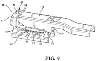
- the connecting assembly 22 also includes a joint part 38, or an adapter, which is made as one integral piece of material and includes a main body portion 40 and a nose portion 41 .
- the main body portion 40 is generally U-shaped in cross-section with a top 42 and a pair of sides 44 and extends longitudinally from a front end 46 to a back end 48.
- the sides 44 of the main body portion 40 extend vertically downwardly in spaced and parallel relationship with one another and transversely to the top 42.
- the sides 44 have axially aligned openings which are circular in shape and which receive the circular projections 34 of the base 32 to allow the joint part 38 to freely pivot relative to the base 32 about a pivot axis.
- the opening 50 extends completely through the main body portion 40 , whereas the opening on the side 44 shown in Figure 3 does not extend completely through the main body portion 40 .
- the nose portion 41 of the joint part 38 is integrally connected with the main body portion 40 at a resilient hinge 52.
- the resilient hinge 52 allows the nose portion 41 to be pivoted forwardly away from the main body portion 40.
- the nose portion 41 also includes a pair of upper locking tangs 54 which are spaced vertically from the resilient hinge 52 and are elevated relative to the top 42 of the main body portion 40 and extend rearwardly towards the main body portion 40.
- the upper locking tangs 54 are spaced laterally from one another on opposite sides of a U-shaped slot 56.
- the top 42 of the main body portion 40 includes a resilient tongue 58 with a button 59 that protrudes upwardly therefrom. Specifically, the button 59 projects upwardly above the top 42 of the main body portion 40.
- the resilient tongue 58 is interconnected with the remainder of the top 42 adjacent the back end 48 and extends longitudinally towards the front end 46 of the main body portion 40.
- the button 59 on the resilient tongue 58 includes a vertical surface 60 which faces longitudinally towards the front end 46 of the main body portion 40 and a ramped surface 62 which faces longitudinally towards the back end 48. The combination of the vertical and ramped surfaces 60, 62 provides the button 59 with a shark fin-like shape.
- Each of the sides 44 of the joint part 38 also includes two vertically spaced and longitudinally extending ledges 64, 66 and presents a groove 68 between the ledges 64, 66.
- each side 44 includes an upper ledge 64 and a lower ledge 66, and each of the ledges 64, 66 has an upper surface and a lower surface.
- the joint part 38 further includes a pair of locking lugs 70, or retention tabs, which extend laterally outwardly.
- the locking lugs 70 are interconnected with the back end 48 of the main body portion 40 via a pair of longitudinally extending legs.
- Each locking lug 70 has a forwardly facing surface which slants upwardly and forwardly from a lower-most edge.
- the longitudinally extending legs are generally rigid.
- the single piece joint part 38 is configured for attachment with a range of different styles and sizes of oscillating wiper arms.
- the joint part 38 is shown in locking engagement with a 19 mm sized bayonet-style wiper arm 72.
- the 19 mm bayonet-style wiper arm 74 is engaged with the joint part 38 by aligning a pair of opposing and laterally inwardly extending legs on the wiper arm 72 with the groove 68 (shown in Figure 3 ) between the ledges 64 , 66 of the joint part 38 and sliding the joint part 38 rearwardly.
- the ramped surface 62 (shown in Figure 3 ) of the button 59 causes the button 59 to automatically pivot downwardly when contacted by a front edge of the wiper arm 72.
- the button 59 then snaps upwardly into a hole on a top wall 74 of the wiper arm 72, to lockingly engage the joint part 38 with the wiper arm 72.
- a top surface of the button 59 is generally flush with the top wall 74 of the wiper arm 72.
- the joint part 38 may be detached from the 19 mm bayonet-style wiper arm 72 by simply pressing the button 59 downwardly through the hole in the top wall 74 of the wiper arm 72 and sliding the joint part 38 forwardly and away from the wiper arm 72.
- the joint part 38 is shown in locking engagement with a 22 mm bayonet-style wiper arm 76.
- the 22 mm bayonet-style wiper arm 76 is engaged with the joint part 38 by aligning the inwardly extending legs of the wiper arm 76 with an underside of the lower ledge 66 (shown in Figure 3 ) such that the legs wrap around and engage with a lower surface of the lower ledge 66 and urging the joint part 38 rearwardly.
- the ramped surface 62 (shown in Figure 3 ) of the button 59 automatically pivots downwardly when contacted by a front edge of the wiper arm 76 and then snaps upwardly into a hole in a top wall 78 of the wiper arm 76.
- the button 59 projects above the top wall 78 of the wiper arm 76.
- the joint part 38 may be detached from the 22 mm bayonet-style wiper arm 76 by simply pressing the button 59 downwardly through the hole in the top wall 78 of the wiper arm 76 and sliding the joint part 38 forwardly and away from the wiper arm 76.
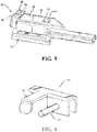
- the joint part 38 is also configured for engagement with a side pin-style wiper arm 80.
- the side pin-style wiper arm 80 is engaged with the joint part 38 by inserting a pin 82 on the wiper arm 80 into the through hole 36 (shown in Figure 3 ) on the projection 34 (also shown in Figure 3 ) of the base 32 and pivoting the joint part 38 relative to the wiper arm 80 until an extension 84 on the wiper arm 80 contacts the top 42 of the main body portion 40 .
- the joint part 38 may be detached from the side pin-style wiper arm 80 by reversing this process.
- the size of the side pin-style wiper arm 80 may either be 19 mm or 22 mm.
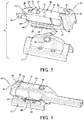
- the joint part 38 is shown in locking engagement with a top lock-style wiper arm 86.
- locking lugs 70 are received within a pair of legs 88 on the side walls of the wiper arm 86, and the joint part 38 is pivoted upwardly relative to the wiper arm 86.
- a tongue (not shown) on a front edge of the wiper arm 86 automatically urges the nose portion 41 of the joint part 38 forwardly to pivot the nose portion 41 about the resilient hinge 52 until the tongue passes through the U-shaped slot 56, thereby allowing the locking tangs 54 on the nose portion 41 to snappingly lock into engagement with the front edge of the wiper arm 86.
- the joint part 38 may be detached from the top lock-style wiper arm 86 by urging the nose portion 41 forwardly to disengage the locking tangs 54 from the front edge of the wiper arm 86, pivoting the joint part 38 away from the wiper arm 86 and disengaging the locking lugs 70 of the joint part 38 from the legs 88 of the wiper arm 86 .
- the joint part 38 is shown in locking engagement with a top lock with window-style wiper arm 90. Similar to the top lock-style wiper arm, the attachment process involves receiving the locking lugs 70 within a pair of legs 92 on the side walls of the wiper arm 90 and pivoting the joint part 38 upwardly relative to the wiper arm 90.
- a tongue (not shown) on a front edge of the wiper arm 90 automatically urges the nose portion 41 of the joint part 38 forwardly to pivot the nose portion 41 about the resilient hinge 52 until the tongue passes through the U-shaped slot 56, thereby allowing the locking tangs 54 to snappingly lock into engagement with the front edge of the wiper arm 90.
- the joint part 38 may be detached from the top lock with window-style wiper arm 90 by urging the nose portion 41 forwardly to disengage the locking tangs 54 from the front edge of the wiper arm 90 , pivoting the joint part 38 away from the wiper arm 90 and disengaging the locking lugs 70 of the joint part 38 from the legs 92 of the wiper arm 90.
Applications Claiming Priority (2)
| Application Number | Priority Date | Filing Date | Title |
|---|---|---|---|
| US201461992621P | 2014-05-13 | 2014-05-13 | |
| PCT/US2015/030482 WO2015175604A1 (en) | 2014-05-13 | 2015-05-13 | Windscreen wiper device |
Publications (2)
| Publication Number | Publication Date |
|---|---|
| EP3142904A1 EP3142904A1 (en) | 2017-03-22 |
| EP3142904B1 true EP3142904B1 (en) | 2018-04-04 |
Family
ID=58009649
Family Applications (1)
| Application Number | Title | Priority Date | Filing Date |
|---|---|---|---|
| EP15724901.2A Not-in-force EP3142904B1 (en) | 2014-05-13 | 2015-05-13 | Windscreen wiper device |
Country Status (2)
| Country | Link |
|---|---|
| EP (1) | EP3142904B1 (zh) |
| CN (1) | CN106507671B (zh) |
Cited By (4)
| Publication number | Priority date | Publication date | Assignee | Title |
|---|---|---|---|---|
| US11040705B2 (en) | 2016-05-19 | 2021-06-22 | Pylon Manufacturing Corp. | Windshield wiper connector |
| US11136002B2 (en) | 2012-02-24 | 2021-10-05 | Pylon Manufacturing Corp. | Wiper blade |
| US11370394B2 (en) | 2017-07-28 | 2022-06-28 | Pylon Manufacturing Corporation | Windshield wiper connector and assembly |
| US11465590B2 (en) | 2017-07-28 | 2022-10-11 | Pylon Manufacturing Corporation | Windshield wiper blade assembly |
Families Citing this family (1)
| Publication number | Priority date | Publication date | Assignee | Title |
|---|---|---|---|---|
| CN113815570B (zh) * | 2021-01-22 | 2023-08-01 | 厦门富可汽车配件有限公司 | 一种连接器及雨刷 |
Family Cites Families (5)
| Publication number | Priority date | Publication date | Assignee | Title |
|---|---|---|---|---|
| CN1211233C (zh) * | 2000-10-28 | 2005-07-20 | 罗伯特-博希股份公司 | 连接雨刷臂和雨刷片的装置以及雨刷片和雨刷臂 |
| EP1854685B1 (en) * | 2006-05-08 | 2009-06-24 | Federal-Mogul S.A. | A windscreen wiper device |
| CN201825006U (zh) * | 2010-06-17 | 2011-05-11 | 东莞鸿益雨刷有限公司 | 雨刷连接组件和雨刷组合 |
| KR101130977B1 (ko) * | 2010-09-10 | 2012-03-29 | 김인규 | 와이퍼 아암용 연결유닛 및 이를 구비한 플랫 와이퍼 블레이드 |
| KR101170905B1 (ko) * | 2010-09-10 | 2012-08-06 | 김인규 | 후크 와이퍼 아암용 연결유닛 및 이를 구비한 플랫 와이퍼 블레이드 |
-
2015
- 2015-05-13 EP EP15724901.2A patent/EP3142904B1/en not_active Not-in-force
- 2015-05-13 CN CN201580033819.0A patent/CN106507671B/zh not_active Expired - Fee Related
Cited By (4)
| Publication number | Priority date | Publication date | Assignee | Title |
|---|---|---|---|---|
| US11136002B2 (en) | 2012-02-24 | 2021-10-05 | Pylon Manufacturing Corp. | Wiper blade |
| US11040705B2 (en) | 2016-05-19 | 2021-06-22 | Pylon Manufacturing Corp. | Windshield wiper connector |
| US11370394B2 (en) | 2017-07-28 | 2022-06-28 | Pylon Manufacturing Corporation | Windshield wiper connector and assembly |
| US11465590B2 (en) | 2017-07-28 | 2022-10-11 | Pylon Manufacturing Corporation | Windshield wiper blade assembly |
Also Published As
| Publication number | Publication date |
|---|---|
| CN106507671B (zh) | 2019-05-14 |
| EP3142904A1 (en) | 2017-03-22 |
| CN106507671A (zh) | 2017-03-15 |
Similar Documents
| Publication | Publication Date | Title |
|---|---|---|
| US9744946B2 (en) | Windscreen wiper device | |
| EP3142904B1 (en) | Windscreen wiper device | |
| EP1681216B1 (en) | Windshield wiper device | |
| KR102022329B1 (ko) | 윈드스크린 와이퍼 장치 | |
| US20200282956A1 (en) | Windshield Wiper Connector | |
| US20160107615A1 (en) | Windscreen wiper device | |
| US20150166017A1 (en) | Windscreen wiper device | |
| EP2849975B1 (en) | Windscreen wiper device and method for manufacturing the same | |
| US20160107616A1 (en) | Windscreen wiper device | |
| US9586560B2 (en) | Windscreen wiper device | |
| CN110505985A (zh) | 挡风玻璃刮水器装置 | |
| KR20170032224A (ko) | 윈드스크린 와이퍼 장치 | |
| EP3206918B1 (en) | Windscreen wiper device | |
| US11608033B2 (en) | Windshield wiper connector | |
| EP1184239B1 (en) | Improvements relating to wiper arm connectors | |
| EP3206919B1 (en) | Windscreen wiper device | |
| WO2022035883A9 (en) | Windshield wiper connector |
Legal Events
| Date | Code | Title | Description |
|---|---|---|---|
| PUAI | Public reference made under article 153(3) epc to a published international application that has entered the european phase |
Free format text: ORIGINAL CODE: 0009012 |
|
| 17P | Request for examination filed |
Effective date: 20161124 |
|
| AK | Designated contracting states |
Kind code of ref document: A1 Designated state(s): AL AT BE BG CH CY CZ DE DK EE ES FI FR GB GR HR HU IE IS IT LI LT LU LV MC MK MT NL NO PL PT RO RS SE SI SK SM TR |
|
| AX | Request for extension of the european patent |
Extension state: BA ME |
|
| DAV | Request for validation of the european patent (deleted) | ||
| DAX | Request for extension of the european patent (deleted) | ||
| GRAP | Despatch of communication of intention to grant a patent |
Free format text: ORIGINAL CODE: EPIDOSNIGR1 |
|
| INTG | Intention to grant announced |
Effective date: 20171127 |
|
| GRAS | Grant fee paid |
Free format text: ORIGINAL CODE: EPIDOSNIGR3 |
|
| GRAA | (expected) grant |
Free format text: ORIGINAL CODE: 0009210 |
|
| AK | Designated contracting states |
Kind code of ref document: B1 Designated state(s): AL AT BE BG CH CY CZ DE DK EE ES FI FR GB GR HR HU IE IS IT LI LT LU LV MC MK MT NL NO PL PT RO RS SE SI SK SM TR |
|
| REG | Reference to a national code |
Ref country code: GB Ref legal event code: FG4D |
|
| REG | Reference to a national code |
Ref country code: CH Ref legal event code: EP |
|
| REG | Reference to a national code |
Ref country code: AT Ref legal event code: REF Ref document number: 985259 Country of ref document: AT Kind code of ref document: T Effective date: 20180415 |
|
| REG | Reference to a national code |
Ref country code: IE Ref legal event code: FG4D |
|
| REG | Reference to a national code |
Ref country code: DE Ref legal event code: R096 Ref document number: 602015009605 Country of ref document: DE |
|
| REG | Reference to a national code |
Ref country code: FR Ref legal event code: PLFP Year of fee payment: 4 |
|
| REG | Reference to a national code |
Ref country code: NL Ref legal event code: MP Effective date: 20180404 |
|
| REG | Reference to a national code |
Ref country code: LT Ref legal event code: MG4D |
|
| PG25 | Lapsed in a contracting state [announced via postgrant information from national office to epo] |
Ref country code: NL Free format text: LAPSE BECAUSE OF FAILURE TO SUBMIT A TRANSLATION OF THE DESCRIPTION OR TO PAY THE FEE WITHIN THE PRESCRIBED TIME-LIMIT Effective date: 20180404 |
|
| PG25 | Lapsed in a contracting state [announced via postgrant information from national office to epo] |
Ref country code: LT Free format text: LAPSE BECAUSE OF FAILURE TO SUBMIT A TRANSLATION OF THE DESCRIPTION OR TO PAY THE FEE WITHIN THE PRESCRIBED TIME-LIMIT Effective date: 20180404 Ref country code: PL Free format text: LAPSE BECAUSE OF FAILURE TO SUBMIT A TRANSLATION OF THE DESCRIPTION OR TO PAY THE FEE WITHIN THE PRESCRIBED TIME-LIMIT Effective date: 20180404 Ref country code: ES Free format text: LAPSE BECAUSE OF FAILURE TO SUBMIT A TRANSLATION OF THE DESCRIPTION OR TO PAY THE FEE WITHIN THE PRESCRIBED TIME-LIMIT Effective date: 20180404 Ref country code: NO Free format text: LAPSE BECAUSE OF FAILURE TO SUBMIT A TRANSLATION OF THE DESCRIPTION OR TO PAY THE FEE WITHIN THE PRESCRIBED TIME-LIMIT Effective date: 20180704 Ref country code: FI Free format text: LAPSE BECAUSE OF FAILURE TO SUBMIT A TRANSLATION OF THE DESCRIPTION OR TO PAY THE FEE WITHIN THE PRESCRIBED TIME-LIMIT Effective date: 20180404 Ref country code: BG Free format text: LAPSE BECAUSE OF FAILURE TO SUBMIT A TRANSLATION OF THE DESCRIPTION OR TO PAY THE FEE WITHIN THE PRESCRIBED TIME-LIMIT Effective date: 20180704 Ref country code: SE Free format text: LAPSE BECAUSE OF FAILURE TO SUBMIT A TRANSLATION OF THE DESCRIPTION OR TO PAY THE FEE WITHIN THE PRESCRIBED TIME-LIMIT Effective date: 20180404 Ref country code: AL Free format text: LAPSE BECAUSE OF FAILURE TO SUBMIT A TRANSLATION OF THE DESCRIPTION OR TO PAY THE FEE WITHIN THE PRESCRIBED TIME-LIMIT Effective date: 20180404 |
|
| PG25 | Lapsed in a contracting state [announced via postgrant information from national office to epo] |
Ref country code: LV Free format text: LAPSE BECAUSE OF FAILURE TO SUBMIT A TRANSLATION OF THE DESCRIPTION OR TO PAY THE FEE WITHIN THE PRESCRIBED TIME-LIMIT Effective date: 20180404 Ref country code: RS Free format text: LAPSE BECAUSE OF FAILURE TO SUBMIT A TRANSLATION OF THE DESCRIPTION OR TO PAY THE FEE WITHIN THE PRESCRIBED TIME-LIMIT Effective date: 20180404 Ref country code: GR Free format text: LAPSE BECAUSE OF FAILURE TO SUBMIT A TRANSLATION OF THE DESCRIPTION OR TO PAY THE FEE WITHIN THE PRESCRIBED TIME-LIMIT Effective date: 20180705 Ref country code: HR Free format text: LAPSE BECAUSE OF FAILURE TO SUBMIT A TRANSLATION OF THE DESCRIPTION OR TO PAY THE FEE WITHIN THE PRESCRIBED TIME-LIMIT Effective date: 20180404 |
|
| REG | Reference to a national code |
Ref country code: CH Ref legal event code: PL |
|
| REG | Reference to a national code |
Ref country code: AT Ref legal event code: MK05 Ref document number: 985259 Country of ref document: AT Kind code of ref document: T Effective date: 20180404 |
|
| PG25 | Lapsed in a contracting state [announced via postgrant information from national office to epo] |
Ref country code: PT Free format text: LAPSE BECAUSE OF FAILURE TO SUBMIT A TRANSLATION OF THE DESCRIPTION OR TO PAY THE FEE WITHIN THE PRESCRIBED TIME-LIMIT Effective date: 20180806 |
|
| REG | Reference to a national code |
Ref country code: DE Ref legal event code: R097 Ref document number: 602015009605 Country of ref document: DE |
|
| REG | Reference to a national code |
Ref country code: BE Ref legal event code: MM Effective date: 20180531 |
|
| PG25 | Lapsed in a contracting state [announced via postgrant information from national office to epo] |
Ref country code: MC Free format text: LAPSE BECAUSE OF FAILURE TO SUBMIT A TRANSLATION OF THE DESCRIPTION OR TO PAY THE FEE WITHIN THE PRESCRIBED TIME-LIMIT Effective date: 20180404 Ref country code: SK Free format text: LAPSE BECAUSE OF FAILURE TO SUBMIT A TRANSLATION OF THE DESCRIPTION OR TO PAY THE FEE WITHIN THE PRESCRIBED TIME-LIMIT Effective date: 20180404 Ref country code: RO Free format text: LAPSE BECAUSE OF FAILURE TO SUBMIT A TRANSLATION OF THE DESCRIPTION OR TO PAY THE FEE WITHIN THE PRESCRIBED TIME-LIMIT Effective date: 20180404 Ref country code: CZ Free format text: LAPSE BECAUSE OF FAILURE TO SUBMIT A TRANSLATION OF THE DESCRIPTION OR TO PAY THE FEE WITHIN THE PRESCRIBED TIME-LIMIT Effective date: 20180404 Ref country code: DK Free format text: LAPSE BECAUSE OF FAILURE TO SUBMIT A TRANSLATION OF THE DESCRIPTION OR TO PAY THE FEE WITHIN THE PRESCRIBED TIME-LIMIT Effective date: 20180404 Ref country code: AT Free format text: LAPSE BECAUSE OF FAILURE TO SUBMIT A TRANSLATION OF THE DESCRIPTION OR TO PAY THE FEE WITHIN THE PRESCRIBED TIME-LIMIT Effective date: 20180404 Ref country code: EE Free format text: LAPSE BECAUSE OF FAILURE TO SUBMIT A TRANSLATION OF THE DESCRIPTION OR TO PAY THE FEE WITHIN THE PRESCRIBED TIME-LIMIT Effective date: 20180404 |
|
| PLBE | No opposition filed within time limit |
Free format text: ORIGINAL CODE: 0009261 |
|
| STAA | Information on the status of an ep patent application or granted ep patent |
Free format text: STATUS: NO OPPOSITION FILED WITHIN TIME LIMIT |
|
| REG | Reference to a national code |
Ref country code: IE Ref legal event code: MM4A |
|
| PG25 | Lapsed in a contracting state [announced via postgrant information from national office to epo] |
Ref country code: CH Free format text: LAPSE BECAUSE OF NON-PAYMENT OF DUE FEES Effective date: 20180531 Ref country code: SM Free format text: LAPSE BECAUSE OF FAILURE TO SUBMIT A TRANSLATION OF THE DESCRIPTION OR TO PAY THE FEE WITHIN THE PRESCRIBED TIME-LIMIT Effective date: 20180404 Ref country code: LI Free format text: LAPSE BECAUSE OF NON-PAYMENT OF DUE FEES Effective date: 20180531 |
|
| 26N | No opposition filed |
Effective date: 20190107 |
|
| PG25 | Lapsed in a contracting state [announced via postgrant information from national office to epo] |
Ref country code: LU Free format text: LAPSE BECAUSE OF NON-PAYMENT OF DUE FEES Effective date: 20180513 |
|
| PG25 | Lapsed in a contracting state [announced via postgrant information from national office to epo] |
Ref country code: IE Free format text: LAPSE BECAUSE OF NON-PAYMENT OF DUE FEES Effective date: 20180513 |
|
| PG25 | Lapsed in a contracting state [announced via postgrant information from national office to epo] |
Ref country code: SI Free format text: LAPSE BECAUSE OF FAILURE TO SUBMIT A TRANSLATION OF THE DESCRIPTION OR TO PAY THE FEE WITHIN THE PRESCRIBED TIME-LIMIT Effective date: 20180404 Ref country code: BE Free format text: LAPSE BECAUSE OF NON-PAYMENT OF DUE FEES Effective date: 20180531 |
|
| GBPC | Gb: european patent ceased through non-payment of renewal fee |
Effective date: 20190513 |
|
| PG25 | Lapsed in a contracting state [announced via postgrant information from national office to epo] |
Ref country code: MT Free format text: LAPSE BECAUSE OF NON-PAYMENT OF DUE FEES Effective date: 20180513 |
|
| PG25 | Lapsed in a contracting state [announced via postgrant information from national office to epo] |
Ref country code: TR Free format text: LAPSE BECAUSE OF FAILURE TO SUBMIT A TRANSLATION OF THE DESCRIPTION OR TO PAY THE FEE WITHIN THE PRESCRIBED TIME-LIMIT Effective date: 20180404 |
|
| PG25 | Lapsed in a contracting state [announced via postgrant information from national office to epo] |
Ref country code: GB Free format text: LAPSE BECAUSE OF NON-PAYMENT OF DUE FEES Effective date: 20190513 |
|
| PG25 | Lapsed in a contracting state [announced via postgrant information from national office to epo] |
Ref country code: CY Free format text: LAPSE BECAUSE OF FAILURE TO SUBMIT A TRANSLATION OF THE DESCRIPTION OR TO PAY THE FEE WITHIN THE PRESCRIBED TIME-LIMIT Effective date: 20180404 Ref country code: MK Free format text: LAPSE BECAUSE OF NON-PAYMENT OF DUE FEES Effective date: 20180404 Ref country code: HU Free format text: LAPSE BECAUSE OF FAILURE TO SUBMIT A TRANSLATION OF THE DESCRIPTION OR TO PAY THE FEE WITHIN THE PRESCRIBED TIME-LIMIT; INVALID AB INITIO Effective date: 20150513 |
|
| PG25 | Lapsed in a contracting state [announced via postgrant information from national office to epo] |
Ref country code: IS Free format text: LAPSE BECAUSE OF FAILURE TO SUBMIT A TRANSLATION OF THE DESCRIPTION OR TO PAY THE FEE WITHIN THE PRESCRIBED TIME-LIMIT Effective date: 20180804 |
|
| PGFP | Annual fee paid to national office [announced via postgrant information from national office to epo] |
Ref country code: FR Payment date: 20200414 Year of fee payment: 6 |
|
| PGFP | Annual fee paid to national office [announced via postgrant information from national office to epo] |
Ref country code: DE Payment date: 20201119 Year of fee payment: 6 |
|
| PGFP | Annual fee paid to national office [announced via postgrant information from national office to epo] |
Ref country code: IT Payment date: 20210521 Year of fee payment: 7 |
|
| REG | Reference to a national code |
Ref country code: DE Ref legal event code: R119 Ref document number: 602015009605 Country of ref document: DE |
|
| PG25 | Lapsed in a contracting state [announced via postgrant information from national office to epo] |
Ref country code: DE Free format text: LAPSE BECAUSE OF NON-PAYMENT OF DUE FEES Effective date: 20211201 |
|
| PG25 | Lapsed in a contracting state [announced via postgrant information from national office to epo] |
Ref country code: FR Free format text: LAPSE BECAUSE OF NON-PAYMENT OF DUE FEES Effective date: 20210531 |
|
| PG25 | Lapsed in a contracting state [announced via postgrant information from national office to epo] |
Ref country code: IT Free format text: LAPSE BECAUSE OF NON-PAYMENT OF DUE FEES Effective date: 20220513 |