EP3142769B1 - Filtre de récupération de liquide - Google Patents
Filtre de récupération de liquide Download PDFInfo
- Publication number
- EP3142769B1 EP3142769B1 EP15792942.3A EP15792942A EP3142769B1 EP 3142769 B1 EP3142769 B1 EP 3142769B1 EP 15792942 A EP15792942 A EP 15792942A EP 3142769 B1 EP3142769 B1 EP 3142769B1
- Authority
- EP
- European Patent Office
- Prior art keywords
- filter
- recovery
- port
- filter assembly
- valve
- Prior art date
- Legal status (The legal status is an assumption and is not a legal conclusion. Google has not performed a legal analysis and makes no representation as to the accuracy of the status listed.)
- Active
Links
- 238000011084 recovery Methods 0.000 title claims description 708
- 239000007788 liquid Substances 0.000 title claims description 455
- 238000011144 upstream manufacturing Methods 0.000 claims description 365
- 239000000463 material Substances 0.000 claims description 190
- 239000012530 fluid Substances 0.000 claims description 173
- 238000004891 communication Methods 0.000 claims description 95
- 238000000034 method Methods 0.000 description 166
- 238000001914 filtration Methods 0.000 description 148
- 239000007789 gas Substances 0.000 description 118
- 230000006870 function Effects 0.000 description 116
- 230000000712 assembly Effects 0.000 description 64
- 238000000429 assembly Methods 0.000 description 64
- 230000002441 reversible effect Effects 0.000 description 64
- 230000002209 hydrophobic effect Effects 0.000 description 55
- 238000012545 processing Methods 0.000 description 53
- 239000012510 hollow fiber Substances 0.000 description 51
- 230000008569 process Effects 0.000 description 49
- 239000010410 layer Substances 0.000 description 45
- 239000012528 membrane Substances 0.000 description 33
- 238000010276 construction Methods 0.000 description 26
- 238000011109 contamination Methods 0.000 description 23
- 239000000853 adhesive Substances 0.000 description 22
- 230000001070 adhesive effect Effects 0.000 description 22
- -1 i.e. Substances 0.000 description 22
- 239000011148 porous material Substances 0.000 description 19
- 230000036961 partial effect Effects 0.000 description 18
- 230000033001 locomotion Effects 0.000 description 16
- 239000002775 capsule Substances 0.000 description 13
- 239000004035 construction material Substances 0.000 description 11
- 230000037361 pathway Effects 0.000 description 11
- IJGRMHOSHXDMSA-UHFFFAOYSA-N Atomic nitrogen Chemical compound N#N IJGRMHOSHXDMSA-UHFFFAOYSA-N 0.000 description 8
- 239000002033 PVDF binder Substances 0.000 description 8
- 238000012986 modification Methods 0.000 description 8
- 230000004048 modification Effects 0.000 description 8
- 229920002981 polyvinylidene fluoride Polymers 0.000 description 8
- 238000003466 welding Methods 0.000 description 8
- 239000004698 Polyethylene Substances 0.000 description 7
- 239000004743 Polypropylene Substances 0.000 description 7
- 229920000573 polyethylene Polymers 0.000 description 7
- 229920001155 polypropylene Polymers 0.000 description 7
- 238000010926 purge Methods 0.000 description 7
- 238000013461 design Methods 0.000 description 6
- 230000005484 gravity Effects 0.000 description 6
- 238000004519 manufacturing process Methods 0.000 description 6
- 229920001343 polytetrafluoroethylene Polymers 0.000 description 6
- 239000004810 polytetrafluoroethylene Substances 0.000 description 6
- 229940058401 polytetrafluoroethylene Drugs 0.000 description 6
- 230000007704 transition Effects 0.000 description 6
- 239000004677 Nylon Substances 0.000 description 5
- 229920001774 Perfluoroether Polymers 0.000 description 5
- 230000009286 beneficial effect Effects 0.000 description 5
- 238000000605 extraction Methods 0.000 description 5
- 229920001778 nylon Polymers 0.000 description 5
- 238000004382 potting Methods 0.000 description 5
- OKTJSMMVPCPJKN-UHFFFAOYSA-N Carbon Chemical compound [C] OKTJSMMVPCPJKN-UHFFFAOYSA-N 0.000 description 4
- JOYRKODLDBILNP-UHFFFAOYSA-N Ethyl urethane Chemical compound CCOC(N)=O JOYRKODLDBILNP-UHFFFAOYSA-N 0.000 description 4
- 239000003570 air Substances 0.000 description 4
- 239000002355 dual-layer Substances 0.000 description 4
- 229910001092 metal group alloy Inorganic materials 0.000 description 4
- 239000000203 mixture Substances 0.000 description 4
- 229910052757 nitrogen Inorganic materials 0.000 description 4
- 229920002492 poly(sulfone) Polymers 0.000 description 4
- 229920000728 polyester Polymers 0.000 description 4
- 238000000746 purification Methods 0.000 description 4
- 238000007789 sealing Methods 0.000 description 4
- 229920002725 thermoplastic elastomer Polymers 0.000 description 4
- QVGXLLKOCUKJST-UHFFFAOYSA-N atomic oxygen Chemical compound [O] QVGXLLKOCUKJST-UHFFFAOYSA-N 0.000 description 3
- 230000004888 barrier function Effects 0.000 description 3
- 230000015572 biosynthetic process Effects 0.000 description 3
- 239000000919 ceramic Substances 0.000 description 3
- 238000007906 compression Methods 0.000 description 3
- 230000006835 compression Effects 0.000 description 3
- 238000005336 cracking Methods 0.000 description 3
- 230000001419 dependent effect Effects 0.000 description 3
- 230000003292 diminished effect Effects 0.000 description 3
- 230000009977 dual effect Effects 0.000 description 3
- 229920001903 high density polyethylene Polymers 0.000 description 3
- 239000004700 high-density polyethylene Substances 0.000 description 3
- 230000001788 irregular Effects 0.000 description 3
- 230000000670 limiting effect Effects 0.000 description 3
- 239000007769 metal material Substances 0.000 description 3
- 239000001301 oxygen Substances 0.000 description 3
- 229910052760 oxygen Inorganic materials 0.000 description 3
- 230000002572 peristaltic effect Effects 0.000 description 3
- 229920003023 plastic Polymers 0.000 description 3
- 239000004033 plastic Substances 0.000 description 3
- 239000004417 polycarbonate Substances 0.000 description 3
- 229920000515 polycarbonate Polymers 0.000 description 3
- 229910001220 stainless steel Inorganic materials 0.000 description 3
- 239000010935 stainless steel Substances 0.000 description 3
- 238000011146 sterile filtration Methods 0.000 description 3
- 230000003075 superhydrophobic effect Effects 0.000 description 3
- XLYOFNOQVPJJNP-UHFFFAOYSA-N water Substances O XLYOFNOQVPJJNP-UHFFFAOYSA-N 0.000 description 3
- 238000009736 wetting Methods 0.000 description 3
- CURLTUGMZLYLDI-UHFFFAOYSA-N Carbon dioxide Chemical compound O=C=O CURLTUGMZLYLDI-UHFFFAOYSA-N 0.000 description 2
- 229920012266 Poly(ether sulfone) PES Polymers 0.000 description 2
- 239000004699 Ultra-high molecular weight polyethylene Substances 0.000 description 2
- MCMNRKCIXSYSNV-UHFFFAOYSA-N Zirconium dioxide Chemical compound O=[Zr]=O MCMNRKCIXSYSNV-UHFFFAOYSA-N 0.000 description 2
- 230000000274 adsorptive effect Effects 0.000 description 2
- 229910052782 aluminium Inorganic materials 0.000 description 2
- XAGFODPZIPBFFR-UHFFFAOYSA-N aluminium Chemical compound [Al] XAGFODPZIPBFFR-UHFFFAOYSA-N 0.000 description 2
- 239000012736 aqueous medium Substances 0.000 description 2
- 238000004500 asepsis Methods 0.000 description 2
- 230000005540 biological transmission Effects 0.000 description 2
- 238000004140 cleaning Methods 0.000 description 2
- 229920001577 copolymer Polymers 0.000 description 2
- 239000002274 desiccant Substances 0.000 description 2
- 238000011143 downstream manufacturing Methods 0.000 description 2
- 239000003814 drug Substances 0.000 description 2
- 229940079593 drug Drugs 0.000 description 2
- 229920001971 elastomer Polymers 0.000 description 2
- 239000000806 elastomer Substances 0.000 description 2
- 229920002313 fluoropolymer Polymers 0.000 description 2
- 239000004811 fluoropolymer Substances 0.000 description 2
- 230000036512 infertility Effects 0.000 description 2
- 239000002184 metal Substances 0.000 description 2
- 229910052751 metal Inorganic materials 0.000 description 2
- 150000002739 metals Chemical class 0.000 description 2
- 230000005012 migration Effects 0.000 description 2
- 238000013508 migration Methods 0.000 description 2
- 229920003052 natural elastomer Polymers 0.000 description 2
- 229920001194 natural rubber Polymers 0.000 description 2
- 238000005192 partition Methods 0.000 description 2
- 229920002239 polyacrylonitrile Polymers 0.000 description 2
- 229920001296 polysiloxane Polymers 0.000 description 2
- 230000001681 protective effect Effects 0.000 description 2
- 238000000926 separation method Methods 0.000 description 2
- HUAUNKAZQWMVFY-UHFFFAOYSA-M sodium;oxocalcium;hydroxide Chemical compound [OH-].[Na+].[Ca]=O HUAUNKAZQWMVFY-UHFFFAOYSA-M 0.000 description 2
- 229920003051 synthetic elastomer Polymers 0.000 description 2
- 239000005061 synthetic rubber Substances 0.000 description 2
- 238000012360 testing method Methods 0.000 description 2
- 229920000785 ultra high molecular weight polyethylene Polymers 0.000 description 2
- 238000013022 venting Methods 0.000 description 2
- 239000000020 Nitrocellulose Substances 0.000 description 1
- 229920002292 Nylon 6 Polymers 0.000 description 1
- 229920002302 Nylon 6,6 Polymers 0.000 description 1
- 239000004952 Polyamide Substances 0.000 description 1
- 239000004695 Polyether sulfone Substances 0.000 description 1
- 239000004642 Polyimide Substances 0.000 description 1
- 239000004809 Teflon Substances 0.000 description 1
- 229920006362 Teflon® Polymers 0.000 description 1
- FJWGYAHXMCUOOM-QHOUIDNNSA-N [(2s,3r,4s,5r,6r)-2-[(2r,3r,4s,5r,6s)-4,5-dinitrooxy-2-(nitrooxymethyl)-6-[(2r,3r,4s,5r,6s)-4,5,6-trinitrooxy-2-(nitrooxymethyl)oxan-3-yl]oxyoxan-3-yl]oxy-3,5-dinitrooxy-6-(nitrooxymethyl)oxan-4-yl] nitrate Chemical compound O([C@@H]1O[C@@H]([C@H]([C@H](O[N+]([O-])=O)[C@H]1O[N+]([O-])=O)O[C@H]1[C@@H]([C@@H](O[N+]([O-])=O)[C@H](O[N+]([O-])=O)[C@@H](CO[N+]([O-])=O)O1)O[N+]([O-])=O)CO[N+](=O)[O-])[C@@H]1[C@@H](CO[N+]([O-])=O)O[C@@H](O[N+]([O-])=O)[C@H](O[N+]([O-])=O)[C@H]1O[N+]([O-])=O FJWGYAHXMCUOOM-QHOUIDNNSA-N 0.000 description 1
- 238000004026 adhesive bonding Methods 0.000 description 1
- 150000001298 alcohols Chemical class 0.000 description 1
- PNEYBMLMFCGWSK-UHFFFAOYSA-N aluminium oxide Inorganic materials [O-2].[O-2].[O-2].[Al+3].[Al+3] PNEYBMLMFCGWSK-UHFFFAOYSA-N 0.000 description 1
- 238000013459 approach Methods 0.000 description 1
- 230000008901 benefit Effects 0.000 description 1
- 229960000074 biopharmaceutical Drugs 0.000 description 1
- 229910002092 carbon dioxide Inorganic materials 0.000 description 1
- 239000001569 carbon dioxide Substances 0.000 description 1
- 229920002678 cellulose Polymers 0.000 description 1
- 239000001913 cellulose Substances 0.000 description 1
- 229920002301 cellulose acetate Polymers 0.000 description 1
- 238000005352 clarification Methods 0.000 description 1
- 230000008878 coupling Effects 0.000 description 1
- 238000010168 coupling process Methods 0.000 description 1
- 238000005859 coupling reaction Methods 0.000 description 1
- 238000002788 crimping Methods 0.000 description 1
- 238000006073 displacement reaction Methods 0.000 description 1
- 238000009826 distribution Methods 0.000 description 1
- 230000000694 effects Effects 0.000 description 1
- 229920006332 epoxy adhesive Polymers 0.000 description 1
- 150000002148 esters Chemical class 0.000 description 1
- 239000000835 fiber Substances 0.000 description 1
- 230000000977 initiatory effect Effects 0.000 description 1
- 238000002347 injection Methods 0.000 description 1
- 239000007924 injection Substances 0.000 description 1
- 229910010272 inorganic material Inorganic materials 0.000 description 1
- 239000011147 inorganic material Substances 0.000 description 1
- 238000011016 integrity testing Methods 0.000 description 1
- 230000003993 interaction Effects 0.000 description 1
- 238000003475 lamination Methods 0.000 description 1
- 230000007246 mechanism Effects 0.000 description 1
- 238000002483 medication Methods 0.000 description 1
- 238000002844 melting Methods 0.000 description 1
- 230000008018 melting Effects 0.000 description 1
- 238000000465 moulding Methods 0.000 description 1
- 229920001220 nitrocellulos Polymers 0.000 description 1
- 238000004806 packaging method and process Methods 0.000 description 1
- 229920002647 polyamide Polymers 0.000 description 1
- 229920006393 polyether sulfone Polymers 0.000 description 1
- 229920001721 polyimide Polymers 0.000 description 1
- 229920000642 polymer Polymers 0.000 description 1
- 239000002952 polymeric resin Substances 0.000 description 1
- 239000004627 regenerated cellulose Substances 0.000 description 1
- 230000001105 regulatory effect Effects 0.000 description 1
- 230000000717 retained effect Effects 0.000 description 1
- 238000012552 review Methods 0.000 description 1
- 239000002904 solvent Substances 0.000 description 1
- 230000000087 stabilizing effect Effects 0.000 description 1
- 238000003860 storage Methods 0.000 description 1
- 239000000126 substance Substances 0.000 description 1
- 230000003319 supportive effect Effects 0.000 description 1
- 229920003002 synthetic resin Polymers 0.000 description 1
- 239000012815 thermoplastic material Substances 0.000 description 1
- 239000010409 thin film Substances 0.000 description 1
- 238000012546 transfer Methods 0.000 description 1
- 238000010977 unit operation Methods 0.000 description 1
- 238000003828 vacuum filtration Methods 0.000 description 1
Images


Classifications
-
- B—PERFORMING OPERATIONS; TRANSPORTING
- B01—PHYSICAL OR CHEMICAL PROCESSES OR APPARATUS IN GENERAL
- B01D—SEPARATION
- B01D29/00—Filters with filtering elements stationary during filtration, e.g. pressure or suction filters, not covered by groups B01D24/00 - B01D27/00; Filtering elements therefor
- B01D29/50—Filters with filtering elements stationary during filtration, e.g. pressure or suction filters, not covered by groups B01D24/00 - B01D27/00; Filtering elements therefor with multiple filtering elements, characterised by their mutual disposition
- B01D29/56—Filters with filtering elements stationary during filtration, e.g. pressure or suction filters, not covered by groups B01D24/00 - B01D27/00; Filtering elements therefor with multiple filtering elements, characterised by their mutual disposition in series connection
- B01D29/58—Filters with filtering elements stationary during filtration, e.g. pressure or suction filters, not covered by groups B01D24/00 - B01D27/00; Filtering elements therefor with multiple filtering elements, characterised by their mutual disposition in series connection arranged concentrically or coaxially
-
- B—PERFORMING OPERATIONS; TRANSPORTING
- B01—PHYSICAL OR CHEMICAL PROCESSES OR APPARATUS IN GENERAL
- B01D—SEPARATION
- B01D29/00—Filters with filtering elements stationary during filtration, e.g. pressure or suction filters, not covered by groups B01D24/00 - B01D27/00; Filtering elements therefor
- B01D29/01—Filters with filtering elements stationary during filtration, e.g. pressure or suction filters, not covered by groups B01D24/00 - B01D27/00; Filtering elements therefor with flat filtering elements
-
- B—PERFORMING OPERATIONS; TRANSPORTING
- B01—PHYSICAL OR CHEMICAL PROCESSES OR APPARATUS IN GENERAL
- B01D—SEPARATION
- B01D29/00—Filters with filtering elements stationary during filtration, e.g. pressure or suction filters, not covered by groups B01D24/00 - B01D27/00; Filtering elements therefor
- B01D29/50—Filters with filtering elements stationary during filtration, e.g. pressure or suction filters, not covered by groups B01D24/00 - B01D27/00; Filtering elements therefor with multiple filtering elements, characterised by their mutual disposition
- B01D29/52—Filters with filtering elements stationary during filtration, e.g. pressure or suction filters, not covered by groups B01D24/00 - B01D27/00; Filtering elements therefor with multiple filtering elements, characterised by their mutual disposition in parallel connection
-
- B—PERFORMING OPERATIONS; TRANSPORTING
- B01—PHYSICAL OR CHEMICAL PROCESSES OR APPARATUS IN GENERAL
- B01D—SEPARATION
- B01D35/00—Filtering devices having features not specifically covered by groups B01D24/00 - B01D33/00, or for applications not specifically covered by groups B01D24/00 - B01D33/00; Auxiliary devices for filtration; Filter housing constructions
- B01D35/16—Cleaning-out devices, e.g. for removing the cake from the filter casing or for evacuating the last remnants of liquid
-
- B—PERFORMING OPERATIONS; TRANSPORTING
- B01—PHYSICAL OR CHEMICAL PROCESSES OR APPARATUS IN GENERAL
- B01D—SEPARATION
- B01D35/00—Filtering devices having features not specifically covered by groups B01D24/00 - B01D33/00, or for applications not specifically covered by groups B01D24/00 - B01D33/00; Auxiliary devices for filtration; Filter housing constructions
- B01D35/30—Filter housing constructions
-
- B—PERFORMING OPERATIONS; TRANSPORTING
- B01—PHYSICAL OR CHEMICAL PROCESSES OR APPARATUS IN GENERAL
- B01D—SEPARATION
- B01D36/00—Filter circuits or combinations of filters with other separating devices
- B01D36/001—Filters in combination with devices for the removal of gas, air purge systems
-
- B—PERFORMING OPERATIONS; TRANSPORTING
- B01—PHYSICAL OR CHEMICAL PROCESSES OR APPARATUS IN GENERAL
- B01D—SEPARATION
- B01D36/00—Filter circuits or combinations of filters with other separating devices
- B01D36/02—Combinations of filters of different kinds
-
- B—PERFORMING OPERATIONS; TRANSPORTING
- B01—PHYSICAL OR CHEMICAL PROCESSES OR APPARATUS IN GENERAL
- B01D—SEPARATION
- B01D2201/00—Details relating to filtering apparatus
- B01D2201/29—Filter cartridge constructions
- B01D2201/291—End caps
-
- B—PERFORMING OPERATIONS; TRANSPORTING
- B01—PHYSICAL OR CHEMICAL PROCESSES OR APPARATUS IN GENERAL
- B01D—SEPARATION
- B01D2201/00—Details relating to filtering apparatus
- B01D2201/34—Seals or gaskets for filtering elements
- B01D2201/347—Radial sealings
-
- B—PERFORMING OPERATIONS; TRANSPORTING
- B01—PHYSICAL OR CHEMICAL PROCESSES OR APPARATUS IN GENERAL
- B01D—SEPARATION
- B01D2201/00—Details relating to filtering apparatus
- B01D2201/40—Special measures for connecting different parts of the filter
- B01D2201/4038—Special measures for connecting different parts of the filter for connecting at least two filtering elements together
Definitions
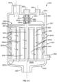
- the filter capsule or housing embodiments may be constructed as permanently sealed structures (with the exception of their various ports or passages), or constructed as reusable units with removable end caps and/or multi-piece housings, permitting access to the filter element therein for replacement or cleaning and reuse, or may be configured as replaceable modular units having pre-installed filter elements.
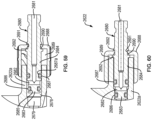
- filter assembly 110 is shown having a relatively tall and narrow configuration, it should be understood that other dimensional and geometrically shaped configurations may be constructed, depending upon the shape and configuration of the filter element contained therein, the placement of the various inlet and outlet ports or passages, the spatial limitations of the apparatus to which the filter assembly is attached, and other factors.
- the various fittings and connectors, illustratively barbed connectors and quick connects (shown in other figures), for the various ports and passages of filter assembly 110 are conventional in the industry and are disclosed as a matter of illustration and not limitation.
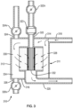
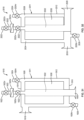
- filter assembly 210 may also perform the intended liquid filter and recovery functions when the liquid flow is reversed through the assembly. It should be understood that to operate filter assembly 210 in the reverse flow direction, the filter assembly may have to be spatially reoriented gravitationally to have reassigned ports positioned in locations to optimize performance with respect to their reassigned functions. For example, a port reassigned as an outlet port should be oriented gravitationally in a low or down position relative to the body of the filter assembly. This requirement may be eliminated in some embodiments if a dip tube (disclosed hereinbelow) is used.
- Reassigned recovery port 222 may include an inline recovery filter reassigned as an upstream filter 223 to preclude further contamination of the liquid prior to being forced through the filter element 230 by the air or gas introduced through the reassigned upstream vent passage 222.
- an inline recovery filter reassigned as an upstream filter 223 to preclude further contamination of the liquid prior to being forced through the filter element 230 by the air or gas introduced through the reassigned upstream vent passage 222.
- the inclusion of a recovery filter reassigned as an upstream filter 223 may limit the reassigned function of port 222 as an upstream drain port, if the recovery filter's properties (such as its hydrophobicity) would prevent liquid from flowing through port 222.
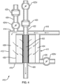
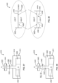
- Filter assembly 210' includes many of the same features as filter assembly 210, and includes a housing or shell designated generally as 211' having a shell wall 212' with an upper end or end cap 214' and an opposite lower end or end cap 216', each secured to, or integral with, shell wall 212'.
- each of the various ports 218' through 224' may include a dedicated valve therein.
- each port may be configured with a valve
- different embodiments of filter assembly 210' may be configured with valves for only some and even none of the ports. Multiple combinations of passages and ports with or without valves are within the contemplation and scope of the disclosure.
- Dedicated valves for selective ports of filter assembly 210' are designated as valves 222v' (reassigned upstream vent valve 224v of filter assembly 210 ) and 224v' (reassigned downstream vent valve 222v of filter assembly 210 ). All optional dedicated valves may be any suitable type of valve, e.g., ball valves, needle valves, known and used in the art.
- An inlet port 218′′′ (reassigned downstream vent port 222 of filter element 210 ) extends from upper end 214′′′ and is in fluid communication with an upstream side internal volume 234′′′ defined by a core 232′′′ of an enclosed filter element 230′′′ (more particularly the upstream designated surface of the filter element, or lumen, as disclosed in more detail herein for the other embodiments).
- An outlet port 220′′′ extends from lower end 216′′′ and is in fluid communication with a downstream internal volume 235" defined by shell 211′′′ and filter element 230′′′ (and more particularly defined by an inner surface of shell 211′′′ and a downstream designated surface of filter element 230′′′ ).
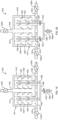
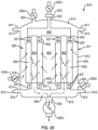
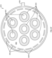
- An outlet port 820 extends substantially parallel to the longitudinal axes of enclosed filter cartridges 830 downwardly from lower end cap 816 and is in liquid communication with filter cores 832, or downstream side of the enclosed filter cartridges via an outlet manifold 850 that connects cores 832 with outlet 820.
- outlet port 820 has a longitudinal axis substantially parallel with the longitudinal axis of the enclosed filter cartridges. It should be understood this orientation can be altered (offset), in similar fashion to inlet port 818 to accommodate specific spatial needs.
- the orientation of inlet port 818 and outlet port 820 may conform to the orientations disclosed in embodiments 210 through 610, or to any orientation known in the art for the arrangement of inlet and outlet ports for filter assemblies.
- the relative diameters of the receiving walls or posts 836 and the cartridges' mounting surfaces can be reversed wherein the inner diameter of the mounting surfaces are greater than the out diameter of the receiving walls or posts.
- the O-rings seal the inner mounting surfaces of the filter cartridges to the outer surfaces of the receiving walls or posts.
- other mounting methods described elsewhere in this disclosure as well as other methods commonly known in the art for attaching filter elements to and into housings, may be used to secure the filter cartridge to the shell wall.
- Tube 1060 and downstream recovery port 1022 may be made from aluminum, stainless steel, metallic alloys, or other metal-based materials.
- Other suitable materials include polymeric materials including, but not limited to, polypropylene, nylon, polyester, polyethylene, PSA and combinations thereof that are generally compatible with the fluids and/or gasses intended to be introduced into the filter assembly as is known in the art.
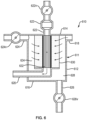
- An upstream vent port 1124 also extends from upper end 1114 to vent an upstream internal volume 1134 described in more detail below.
- an optional upstream drain port (not shown) may be included and extend from lower end 1116 to drain liquids from upstream internal volume 1134.
- This general external configuration of filter assembly 1110 is similar to filter assembly 510 of FIG. 5 , with the exception of the absence of an upstream drain port and the location of ports 1122 compared with the location of port 522, which is reoriented to lower end 1116 due to the use of tube 1160.
- the assembly may be maintained in the orientation shown schematically in FIG. 15 , such that outlet port 1120, reassigned as an inlet port, remains located at the gravitational bottom or low position. It should be noted that reorientation is not necessary for this functional configuration compared to the orientation shown as the reassigned outlet port is located at the gravitational bottom or low position in the orientation shown schematically in FIG. 15 .
- Upstream vent port 1124 is reassigned as a downstream recovery port and will incorporate an inline recovery filter similar to, or the same as, recovery filter 1123.
- Recovery port 1122 is reassigned as an upstream vent port and often maintained in a closed condition during the main filtering operation.
- recovery filters 1123 on ports 1122 are optional in this functional configuration.
- liquid introduced into port 1120 (with valve 1120v open, if present), flows into cores 1132 (or the lumen of the filter elements if constructed from, for example, hollow fiber or tubular material), and radially outwardly through filter elements 1130 into internal volume 1134 (now a downstream volume) and out of the filter assembly through port 1118 as processed liquid.
- any the remaining port(s), if present, is/are maintained in a closed condition (by, for example, closing their associated valve) or could be eliminated from the embodiment, as shown in FIG. 15 , as use of additional downstream ports risk contamination of the downstream filtered liquid when not coupled with a recovery filter.
- valve 1020v may be closed to cease flow.
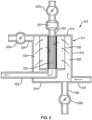
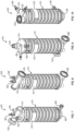
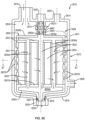
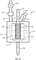
- a filter assembly shown designated generally as 1610 incorporates the same features as filter assembly 510 shown in FIG. 5 in a gravitationally opposite orientation and with the addition of an outlet dip tube 1668.
- Outlet dip tube 1668 creates a partition within the downstream side of element 1630 and is in liquid communication with outlet port 1620 and core 1632. The partition formed by outlet dip tube 1668 directs fluid introduced through recovery port 1622 down to the bottom of core 1632 before flowing out through dip tube 1668 and through outlet port 1620.
- valves can be configured in accordance with any of the constructions disclosed herein, or may be constructed in accordance with any other construction known in the art. It should be understood that the valves may be structured as pinch valves or clamps attached externally to the tubing as known in the art. Such pinch valves or clamps perform the intended function to compress the tubing such that flow is partially or completely restricted.
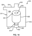
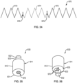
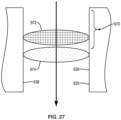
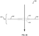
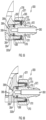
- a lower non-porous or otherwise flow-restrictive layer 2458 is secured to upper layer 2456 at one or more points such that it is held in position, but may be bent or angled away from layer 2458 if force is applied.
- FIG. 39 it is shown that a center section of layer 2458 is secured to upper layer 2456, while an outer annular (or other shape) segment 2460 of lower layer 2458 is free to rotate or bend away from upper layer 2456, and is dimensioned to contact the inner wall of recovery port 2322 when flattened against upper layer 2456 so as to create a seal when in a closed position.
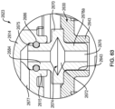
- channel 2680a may also be formed on the inner wall of sleeve 2643 to receive the O-ring and have an inner surface of the O-ring register against a substantially smooth outer surface of lower post 2678a.
- more than one O-ring and/or O-ring/channel combination may be used to secure each post and sleeve combination as shown in FIG. 22 .
- other means known in the art to attach recovery filter subassembly 2623 to filter element 2630 may be used and remain with the scope of the disclosure.
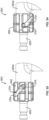
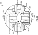
- Drain valve stem distal segment 2696 has a drain valve stem annular channel 2697 formed thereon and dimensioned to receive a drain valve O-ring 2698.
- An outer surface of drain valve O-ring 2698 registers against the lumen wall of the drain port channel to form a substantially liquid-tight seal.
- the seal formed by this O-ring is meant to be a sliding seal in that the valve stem can freely move within drain port 2626a along a longitudinal axis of the drain port without compromising the seal function of the O-ring. Drain valve stem 2673 motion within the port is restricted by adjustable drain port valve cap 2671 disclosed in detail below.
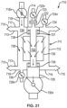
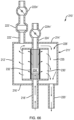
- a recovery port 2742 is connected to, and extends from, process fluid pathway 2780.
- Recovery filter 2743 is secured in-line with recovery port 2742 and houses recovery filter material 2725.
- downstream is used to refer to locations, components, fluids, etc. located on the same side of recovery filter material 2725 as process fluid pathway 2780 and the term “upstream” is used to refer to locations, components, fluids, etc. located on the opposite side of recovery filter material 2725 and process fluid pathway 2780.
Landscapes
- Chemical & Material Sciences (AREA)
- Chemical Kinetics & Catalysis (AREA)
- Separation Using Semi-Permeable Membranes (AREA)
- Filtration Of Liquid (AREA)
- Filtering Of Dispersed Particles In Gases (AREA)
Claims (14)
- Ensemble filtre de récupération de liquide (2610) comprenant :un logement de filtre (2611) ayant une extrémité ou coiffe d'extrémité supérieure (2614), une extrémité ou coiffe d'extrémité inférieure (2616) opposée à l'extrémité supérieure, et une paroi externe (2612) s'étendant entre l'extrémité supérieure et l'extrémité inférieure, le logement définissant un volume interne (2628) ;un élément de filtre (2630) disposé au sein du logement de filtre (2611), l'élément de filtre ayant un côté désigné amont (2634) et un côté désigné aval ou noyau de filtre (2632), dans lequel un volume amont est défini par le logement de filtre (2611) et le côté désigné amont (2634) de l'élément de filtre ;un orifice d'entrée (2618) s'étendant à partir du logement de filtre, l'orifice d'entrée communiquant fluidiquement avec le volume amont (2634) ;un orifice de sortie (2620) s'étendant à partir du logement de filtre, l'orifice de sortie étant en communication fluidique avec le côté désigné aval (2632) de l'élément de filtre ; et,un orifice de récupération (2622a) s'étendant à partir du logement de filtre, distinct de l'orifice de sortie (2620), définissant une lumière ou un canal et conçu pour introduire un gaz stérile ou autrement exempt de contaminants dans le côté aval (2632) de l'ensemble filtre (2610) ; caractérisé parl'orifice de récupération (2622a) étant en communication fluidique avec le côté aval (2632) de l'élément de filtre (2630) ;l'extrémité ou coiffe d'extrémité supérieure (2614) définissant un raccord d'orifice de récupération s'étendant radialement (2621a) qui définit un canal de récupération (2677), etun sous-ensemble filtre de récupération (2623) fixé à l'intérieur du logement de filtre (2611), comprenant un logement de filtre de récupération (2670) qui définit une chambre de filtre de récupération (2672), un filtre de récupération (2674) fixé dans la chambre de filtre (2672), et des parties définissant un canal de fluide (2676),dans lequel le canal de récupération (2677) raccorde fluidiquement le canal de fluide (2676) à la lumière ou au canal de l'orifice de récupération (2622a),dans lequel le canal de fluide (2676) est en communication fluidique avec le noyau de filtre (2632), le filtre de récupération (2674) et avec la lumière ou le canal de l'orifice de récupération (2622a), etdans lequel le sous-ensemble filtre de récupération (2623) est positionné entre l'élément de filtre et l'orifice de récupération (2622a).
- Ensemble filtre de récupération de liquide selon la revendication 1 dans lequel le sous-ensemble filtre de récupération comprend en outre un poste inférieur creux d'ensemble filtre de récupération (2678a) s'étendant vers le bas à partir du logement de filtre de récupération (2670) en communication fluidique avec le canal d'ensemble filtre de récupération et l'élément de filtre côté aval, dans lequel l'élément de filtre comprend une cartouche filtrante ayant une paroi de cartouche, une coiffe d'extrémité supérieure de cartouche et une coiffe d'extrémité inférieure de cartouche l'une et l'autre fixées à la paroi de cartouche, dans lequel la combinaison de la paroi et des coiffes d'extrémité de cartouche définit une chambre de cartouche au sein de laquelle un matériau filtrant est fixé ; dans lequel la coiffe d'extrémité supérieure de cartouche définit un manchon supérieur de cartouche (2643) s'étendant vers le haut à partir de la coiffe d'extrémité et dimensionné pour recevoir le poste inférieur d'ensemble filtre de récupération (2678a) fixé dans le manchon, dans lequel le poste inférieur d'ensemble filtre de récupération comprend en outre au moins un canal de joint torique inférieur (2680a) formé sur sa surface extérieure, et dans lequel le sous-ensemble filtre comprend en outre au moins un joint torique inférieur d'ensemble filtre de récupération (2682) fixé dans l'au moins un canal de joint torique inférieur, et dans lequel l'au moins un joint torique inférieur s'aligne contre une paroi interne du manchon supérieur de cartouche pour créer un joint sensiblement étanche aux liquides et étanche aux gaz.
- Ensemble filtre de récupération de liquide selon la revendication 2 dans lequel le sous-ensemble filtre de récupération comprend en outre un poste supérieur creux d'ensemble filtre de récupération (2684) s'étendant vers le haut à partir du logement de filtre de récupération en communication fluidique avec la chambre d'ensemble filtre de récupération et l'orifice de récupération et dans lequel l'extrémité supérieure de logement de filtre définit un manchon d'extrémité supérieure dimensionné pour recevoir le poste supérieur d'extrémité de filtre de récupération fixé dans le manchon d'extrémité supérieure, dans lequel le poste supérieur d'ensemble filtre de récupération comprend en outre au moins un canal de joint torique supérieur (2675) formé sur sa surface extérieure, et dans lequel le sous-ensemble filtre comprend en outre au moins un joint torique supérieur d'ensemble filtre de récupération (2688) fixé dans le canal de joint torique supérieur, et dans lequel l'au moins un joint torique supérieur s'aligne contre une paroi interne du manchon d'extrémité supérieure pour créer un joint sensiblement étanche aux liquides et étanche aux gaz.
- Ensemble filtre de récupération de liquide selon la revendication 2 dans lequel la coiffe d'extrémité inférieure de cartouche définit un poste inférieur creux de cartouche (2633) s'étendant vers le bas à partir du capuchon d'extrémité inférieure en communication fluidique avec le côté aval de l'élément de filtre et l'orifice de sortie (2620), et dans lequel l'extrémité inférieure de logement de filtre définit un manchon d'extrémité inférieure s'étendant vers le haut à partir de l'extrémité inférieure et dimensionné pour recevoir le poste inférieur de cartouche fixé dans le manchon d'extrémité inférieure, dans lequel le poste inférieur de cartouche comprend en outre au moins un canal de joint torique de poste inférieur de cartouche formé sur sa surface extérieure, et dans lequel le sous-ensemble filtre comprend en outre au moins un joint torique de poste inférieur de cartouche fixé dans l'au moins un canal de joint torique de poste inférieur de cartouche, et dans lequel l'au moins un joint torique de poste inférieur de cartouche s'aligne contre une paroi interne du manchon d'extrémité inférieure pour créer un joint sensiblement étanche aux liquides et étanche aux gaz.
- Ensemble filtre de récupération de liquide selon la revendication 2 dans lequel la coiffe d'extrémité inférieure de cartouche définit (2837a) un poste inférieur creux de cartouche (2833) s'étendant vers le bas à partir de la coiffe d'extrémité inférieure en communication fluidique avec le côté aval de l'élément de filtre et l'orifice de sortie, et dans lequel le poste inférieur de cartouche est fixé au sein de l'orifice de sortie, dans lequel le poste inférieur de cartouche comprend en outre au moins un canal de joint torique de poste inférieur de cartouche (2839) formé sur sa surface extérieure, dans lequel le sous-ensemble filtre comprend en outre au moins un joint torique de poste inférieur de cartouche (2841) fixé dans l'au moins un canal de joint torique de poste inférieur de cartouche, et dans lequel l'au moins un joint torique de poste inférieur de cartouche s'aligne contre une paroi interne de l'orifice de sortie pour créer un joint sensiblement étanche aux liquides et étanche aux gaz.
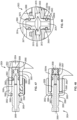
- Ensemble filtre de récupération de liquide selon la revendication 1 dans lequel l'orifice de récupération comprend en outre une vanne de purge ajustable d'orifice de récupération (2622) fixée à l'orifice, dans lequel la vanne de purge comprend une tige de vanne de purge d'orifice de récupération (2680) fixée dans l'orifice de récupération et une coiffe de vanne de purge d'orifice de récupération fixée à la tige de vanne de purge de récupération et à l'orifice de récupération, dans lequel la tige de vanne de purge de récupération définit un canal de tige de vanne de purge de récupération (2681) ouvert au niveau d'une extrémité distale par rapport à l'orifice de récupération et fermé axialement au niveau d'une extrémité proximale par rapport à l'orifice de récupération, dans lequel la vanne de purge comprend en outre un alésage radial de tige de vanne de récupération (2682) formé dans la tige de vanne en communication fluidique avec le canal de tige de vanne et l'orifice de récupération.
- Ensemble filtre de récupération de liquide selon la revendication 6 dans lequel la lumière ou le canal de l'orifice de récupération définit un canal interne d'orifice de récupération (2679) et un canal externe d'orifice de récupération (2678) en communication fluidique avec le canal interne, dans lequel le canal interne a un diamètre en coupe inférieur au diamètre en coupe du canal externe, dans lequel la jonction des deux canaux forme un épaulement ou une surface effilée, dans lequel la tige de vanne de purge de récupération comprend en outre un premier canal de joint torique de tige de vanne de récupération (2685) formé entre l'alésage radial et l'extrémité proximale de tige de vanne, l'ensemble filtre comprenant en outre un premier joint torique de tige de vanne de récupération (2686) fixé dans le premier canal de joint torique de tige de vanne de récupération et dimensionné pour s'aligner contre la jonction des canaux interne et externe d'orifice de récupération lorsque la vanne de purge de récupération est dans une position fermée.
- Ensemble filtre de récupération de liquide selon la revendication 7 dans lequel la tige de vanne d'orifice de récupération comprend en outre un second canal de joint torique de tige de vanne de récupération (2687a) formé entre l'extrémité distale de la tige de vanne et l'alésage radial, l'ensemble filtre comprenant en outre un second joint torique de tige de vanne de récupération (2687) fixé dans le second canal de joint torique de tige de vanne de récupération et dimensionné pour s'aligner contre la paroi du canal externe d'orifice de récupération.
- Ensemble filtre de récupération de liquide selon la revendication 8 dans lequel l'orifice de récupération comprend en outre une broche (2688b) s'étendant radialement vers l'extérieur à partir de l'orifice de récupération, et dans lequel la coiffe de vanne de purge de récupération définit une fente hélicoïdale (2688a) dimensionnée pour recevoir la broche, dans lequel des extrémités de la fente définissent la plage de déplacement de la tige de vanne d'orifice de récupération, dans lequel la coiffe de vanne de purge de récupération comprend en outre une crête annulaire de coiffe de récupération faisant saillie radialement vers l'intérieur au niveau d'une extrémité distale par rapport à l'orifice de récupération, et dans lequel la tige de vanne d'orifice de récupération définit un canal de réception de coiffe de récupération sur sa surface extérieure au sein duquel la crête est positionnée, dans lequel le diamètre en coupe d'une ouverture définie par la crête est supérieur au diamètre en coupe du canal de réception de coiffe de récupération et inférieur au diamètre en coupe de la tige de vanne d'orifice de récupération pour permettre la rotation libre de la crête au sein du canal.
- Ensemble filtre de récupération de liquide selon la revendication 1 comprenant en outre un orifice de mise à l'air amont (2624) s'étendant à partir du logement de filtre, dans lequel l'orifice de mise à l'air amont est en communication fluidique avec le volume amont, dans lequel l'orifice de récupération comprend en outre une vanne de purge ajustable d'orifice de mise à l'air fixée à l'orifice, dans lequel la vanne de purge comprend une tige de vanne de purge d'orifice de mise à l'air (2655) fixée dans l'orifice de mise à l'air et une coiffe de vanne de purge d'orifice de mise à l'air (2652) fixée à la tige de vanne de purge d'orifice de mise à l'air et à l'orifice de mise à l'air.
- Ensemble filtre de récupération de liquide selon la revendication 10 dans lequel la tige de vanne de purge d'orifice de mise à l'air (2655) définit un canal de tige de vanne de purge d'orifice de mise à l'air (2656) ouvert au niveau d'une extrémité distale par rapport à l'orifice de mise à l'air et fermé axialement au niveau d'une extrémité proximale par rapport à l'orifice de mise à l'air, dans lequel la vanne de purge comprend en outre un alésage radial de tige de vanne de mise à l'air formé dans la tige de vanne en communication fluidique avec le canal de tige de vanne et l'orifice de mise à l'air, et dans lequel l'orifice de mise à l'air définit un canal interne d'orifice de mise à l'air (2654) et un canal externe d'orifice de mise à l'air (2653) en communication fluidique avec le canal interne, dans lequel le canal interne a un diamètre en coupe inférieur au diamètre en coupe du canal externe, dans lequel la jonction des deux canaux forme un épaulement ou une surface effilée, dans lequel la tige de vanne de purge de mise à l'air comprend en outre un premier canal de joint torique de tige de vanne de mise à l'air (2660) formé entre l'alésage radial et l'extrémité proximale de tige de vanne, l'ensemble filtre comprenant en outre un premier joint torique de tige de vanne de mise à l'air (2661) fixé dans le premier canal de joint torique de tige de vanne de mise à l'air et dimensionné pour s'aligner contre la jonction des canaux interne et externe d'orifice de mise à l'air lorsque la vanne de purge de mise à l'air est dans une position fermée.
- Ensemble filtre de récupération de liquide selon la revendication 11 dans lequel la tige de vanne d'orifice de mise à l'air comprend en outre un second canal de joint torique de tige de vanne de mise à l'air (2662) formé entre l'extrémité distale de la tige de vanne et l'alésage radial, l'ensemble filtre comprenant en outre un second joint torique de tige de vanne de mise à l'air (2663) fixé dans le second canal de joint torique de tige de vanne de mise à l'air et dimensionné pour s'aligner contre la paroi du canal externe d'orifice de mise à l'air.
- Ensemble filtre de récupération de liquide selon la revendication 12 dans lequel l'orifice de mise à l'air comprend en outre une broche (2705) s'étendant radialement vers l'extérieur à partir de l'orifice de mise à l'air, et dans lequel la coiffe de vanne de purge de mise à l'air définit une fente hélicoïdale dimensionnée pour recevoir la broche, dans lequel des extrémités de la fente définissent la plage de déplacement de la tige de vanne d'orifice de mise à l'air.
- Ensemble filtre de récupération de liquide selon la revendication 13 dans lequel la coiffe de vanne de purge de mise à l'air (2652) comprend en outre une crête annulaire de coiffe de mise à l'air faisant saillie radialement vers l'intérieur (2666) au niveau d'une extrémité distale par rapport à l'orifice de mise à l'air, et dans lequel la tige de vanne d'orifice de mise à l'air définit un canal de réception de coiffe de mise à l'air (2667) sur sa surface extérieure au sein duquel la crête est positionnée, dans lequel le diamètre en coupe d'une ouverture définie par la crête est supérieur au diamètre en coupe du canal de réception de coiffe de mise à l'air (2677) et inférieur au diamètre en coupe de la tige de vanne d'orifice de mise à l'air (2655) pour permettre la rotation libre de la crête au sein du canal.
Priority Applications (1)
| Application Number | Priority Date | Filing Date | Title |
|---|---|---|---|
| EP23190302.2A EP4342559A2 (fr) | 2014-05-12 | 2015-05-12 | Filtre de récupération de liquide |
Applications Claiming Priority (3)
| Application Number | Priority Date | Filing Date | Title |
|---|---|---|---|
| US201461992029P | 2014-05-12 | 2014-05-12 | |
| US14/521,437 US9861916B2 (en) | 2012-04-30 | 2014-10-22 | Liquid recovery filter |
| PCT/US2015/030280 WO2015175470A1 (fr) | 2014-05-12 | 2015-05-12 | Filtre de récupération de liquide |
Related Child Applications (1)
| Application Number | Title | Priority Date | Filing Date |
|---|---|---|---|
| EP23190302.2A Division EP4342559A2 (fr) | 2014-05-12 | 2015-05-12 | Filtre de récupération de liquide |
Publications (3)
| Publication Number | Publication Date |
|---|---|
| EP3142769A1 EP3142769A1 (fr) | 2017-03-22 |
| EP3142769A4 EP3142769A4 (fr) | 2018-02-28 |
| EP3142769B1 true EP3142769B1 (fr) | 2023-08-09 |
Family
ID=54480525
Family Applications (2)
| Application Number | Title | Priority Date | Filing Date |
|---|---|---|---|
| EP23190302.2A Pending EP4342559A2 (fr) | 2014-05-12 | 2015-05-12 | Filtre de récupération de liquide |
| EP15792942.3A Active EP3142769B1 (fr) | 2014-05-12 | 2015-05-12 | Filtre de récupération de liquide |
Family Applications Before (1)
| Application Number | Title | Priority Date | Filing Date |
|---|---|---|---|
| EP23190302.2A Pending EP4342559A2 (fr) | 2014-05-12 | 2015-05-12 | Filtre de récupération de liquide |
Country Status (4)
| Country | Link |
|---|---|
| EP (2) | EP4342559A2 (fr) |
| CN (2) | CN111974056A (fr) |
| BR (2) | BR122020025290B1 (fr) |
| WO (1) | WO2015175470A1 (fr) |
Families Citing this family (6)
| Publication number | Priority date | Publication date | Assignee | Title |
|---|---|---|---|---|
| CN108671604A (zh) * | 2018-07-06 | 2018-10-19 | 苏州新纽顿环保科技有限公司 | 一种智能过滤机及其使用方法 |
| CN108759959B (zh) * | 2018-08-08 | 2024-03-22 | 合肥精都机电仪表有限公司 | 一种具有防窜位功能的消气器 |
| CN111087043A (zh) * | 2019-12-11 | 2020-05-01 | 芜湖成德龙过滤设备有限公司 | 一种带有尼龙膜的滤芯以及过滤器 |
| WO2021220083A1 (fr) * | 2020-04-30 | 2021-11-04 | Precision Planting Llc | Système d'air à commande pneumatique multiplexé pour filtration de suspension |
| CN112473255B (zh) * | 2020-12-08 | 2022-04-26 | 福建龙净环保股份有限公司 | 一种滤料安装结构、安装方法及烟气净化设备 |
| CN114768399B (zh) * | 2022-05-18 | 2024-01-30 | 深圳市诺丞智能科技有限公司 | 一种具有分箱清灰结构的气箱脉冲袋收尘器及其实施方法 |
Citations (3)
| Publication number | Priority date | Publication date | Assignee | Title |
|---|---|---|---|---|
| US2031935A (en) * | 1933-04-21 | 1936-02-25 | Cuno Eng Corp | Filter |
| DE10315506A1 (de) * | 2003-04-04 | 2004-10-14 | Siemens Ag | Kraftstofffilter für ein Kraftfahrzeug |
| EP1504801A1 (fr) * | 2003-08-05 | 2005-02-09 | ArvinMeritor Technology, LLC | Filtre a combustible avec deviateur de flux |
Family Cites Families (15)
| Publication number | Priority date | Publication date | Assignee | Title |
|---|---|---|---|---|
| CA1170195A (fr) * | 1981-01-21 | 1984-07-03 | Denis S. Ward | Cartouche filtrante |
| US5462679A (en) * | 1993-09-16 | 1995-10-31 | Nelson Industries, Inc. | Apparatus and method for in situ cleaning of oil filter |
| JPH08192006A (ja) * | 1995-01-13 | 1996-07-30 | Pall Corp | 濾過器 |
| DE19636067A1 (de) * | 1995-09-18 | 1997-03-20 | Barmag Barmer Maschf | Filtervorrichtung zur Filtration von Kunststoffschmelze |
| US6517711B1 (en) * | 1998-10-02 | 2003-02-11 | Wastech International Inc. | Waste treatment system |
| DE19905645C1 (de) * | 1999-02-11 | 2000-10-26 | Sartorius Gmbh | Filteraufsatz zur Vakuumfiltration |
| US20080121583A1 (en) * | 2006-06-19 | 2008-05-29 | Nohren John E | Portable Universal Flow Filter |
| CN201454215U (zh) * | 2009-06-29 | 2010-05-12 | 海宁圣华过滤设备有限公司 | 一种过滤机 |
| DE102010035981A1 (de) * | 2010-09-01 | 2012-03-01 | Hydac Filtertechnik Gmbh | Bauteil für eine Filtereinheit zur Filtration von Fluiden und Verfahren zur Herstellung eines derartigen Bauteils |
| DE102011016464B4 (de) * | 2011-04-08 | 2016-12-29 | Beko Technologies Gmbh | Strömungsoptimierter Filterkopf |
| IL219645A (en) * | 2011-05-12 | 2016-10-31 | Strauss Water Ltd | Water filtration device |
| CN202113671U (zh) * | 2011-06-13 | 2012-01-18 | 世隆机械(大连)有限公司 | 气压排污式涡流过滤装置 |
| CN202478697U (zh) * | 2012-03-09 | 2012-10-10 | 德芮克化工设备(昆山)有限公司 | 过滤器 |
| US9757666B2 (en) * | 2012-04-30 | 2017-09-12 | Saint-Gobain Performance Plastics Corporation | Liquid recovery filter |
| CN203476923U (zh) * | 2013-09-05 | 2014-03-12 | 鞍钢股份有限公司 | 一种液压过滤器内油液的回收装置 |
-
2015
- 2015-05-12 BR BR122020025290-1A patent/BR122020025290B1/pt active IP Right Grant
- 2015-05-12 CN CN202010314569.0A patent/CN111974056A/zh active Pending
- 2015-05-12 EP EP23190302.2A patent/EP4342559A2/fr active Pending
- 2015-05-12 CN CN201580035781.0A patent/CN106999806B/zh active Active
- 2015-05-12 BR BR112016026576-9A patent/BR112016026576B1/pt active IP Right Grant
- 2015-05-12 WO PCT/US2015/030280 patent/WO2015175470A1/fr active Application Filing
- 2015-05-12 EP EP15792942.3A patent/EP3142769B1/fr active Active
Patent Citations (3)
| Publication number | Priority date | Publication date | Assignee | Title |
|---|---|---|---|---|
| US2031935A (en) * | 1933-04-21 | 1936-02-25 | Cuno Eng Corp | Filter |
| DE10315506A1 (de) * | 2003-04-04 | 2004-10-14 | Siemens Ag | Kraftstofffilter für ein Kraftfahrzeug |
| EP1504801A1 (fr) * | 2003-08-05 | 2005-02-09 | ArvinMeritor Technology, LLC | Filtre a combustible avec deviateur de flux |
Also Published As
| Publication number | Publication date |
|---|---|
| WO2015175470A1 (fr) | 2015-11-19 |
| WO2015175470A9 (fr) | 2016-01-07 |
| EP3142769A1 (fr) | 2017-03-22 |
| CN106999806B (zh) | 2020-05-12 |
| CN111974056A (zh) | 2020-11-24 |
| BR122020025290B1 (pt) | 2022-10-11 |
| BR112016026576B1 (pt) | 2022-06-14 |
| EP4342559A2 (fr) | 2024-03-27 |
| BR112016026576A2 (fr) | 2017-08-15 |
| EP3142769A4 (fr) | 2018-02-28 |
| CN106999806A (zh) | 2017-08-01 |
Similar Documents
| Publication | Publication Date | Title |
|---|---|---|
| US11890559B2 (en) | Liquid recovery filter | |
| EP3142769B1 (fr) | Filtre de récupération de liquide | |
| EP2844363B1 (fr) | Filtre de récupération de liquide | |
| US8808552B2 (en) | Stackable filter cup apparatus and method | |
| US20070131604A1 (en) | Filter unit with deaerating mechanism | |
| EP2585201B1 (fr) | Module de filtre à fluide comportant un bouchon scellé | |
| US7122120B2 (en) | Filter element, particularly for the static or dead-end filtration of fluids, and corresponding filter device | |
| EP0078419B1 (fr) | Dispositif de filtration pharmaceutique à rejeter | |
| US20060213827A1 (en) | Filter device including pleated filter incorporated in a housing | |
| US20240173656A1 (en) | Liquid Recovery Filter | |
| US11203537B1 (en) | Method for filtering liquid mixture | |
| EP3747527B1 (fr) | Capsule filtrante et procédé d'utilisation |
Legal Events
| Date | Code | Title | Description |
|---|---|---|---|
| STAA | Information on the status of an ep patent application or granted ep patent |
Free format text: STATUS: THE INTERNATIONAL PUBLICATION HAS BEEN MADE |
|
| PUAI | Public reference made under article 153(3) epc to a published international application that has entered the european phase |
Free format text: ORIGINAL CODE: 0009012 |
|
| STAA | Information on the status of an ep patent application or granted ep patent |
Free format text: STATUS: REQUEST FOR EXAMINATION WAS MADE |
|
| 17P | Request for examination filed |
Effective date: 20161201 |
|
| AK | Designated contracting states |
Kind code of ref document: A1 Designated state(s): AL AT BE BG CH CY CZ DE DK EE ES FI FR GB GR HR HU IE IS IT LI LT LU LV MC MK MT NL NO PL PT RO RS SE SI SK SM TR |
|
| AX | Request for extension of the european patent |
Extension state: BA ME |
|
| DAV | Request for validation of the european patent (deleted) | ||
| DAX | Request for extension of the european patent (deleted) | ||
| A4 | Supplementary search report drawn up and despatched |
Effective date: 20180125 |
|
| RIC1 | Information provided on ipc code assigned before grant |
Ipc: B01D 36/02 20060101ALI20180119BHEP Ipc: B01D 29/66 20060101AFI20180119BHEP Ipc: B01D 29/58 20060101ALI20180119BHEP Ipc: B01D 29/01 20060101ALI20180119BHEP |
|
| STAA | Information on the status of an ep patent application or granted ep patent |
Free format text: STATUS: EXAMINATION IS IN PROGRESS |
|
| 17Q | First examination report despatched |
Effective date: 20190517 |
|
| STAA | Information on the status of an ep patent application or granted ep patent |
Free format text: STATUS: EXAMINATION IS IN PROGRESS |
|
| STAA | Information on the status of an ep patent application or granted ep patent |
Free format text: STATUS: EXAMINATION IS IN PROGRESS |
|
| GRAP | Despatch of communication of intention to grant a patent |
Free format text: ORIGINAL CODE: EPIDOSNIGR1 |
|
| STAA | Information on the status of an ep patent application or granted ep patent |
Free format text: STATUS: GRANT OF PATENT IS INTENDED |
|
| INTG | Intention to grant announced |
Effective date: 20230222 |
|
| GRAS | Grant fee paid |
Free format text: ORIGINAL CODE: EPIDOSNIGR3 |
|
| GRAA | (expected) grant |
Free format text: ORIGINAL CODE: 0009210 |
|
| STAA | Information on the status of an ep patent application or granted ep patent |
Free format text: STATUS: THE PATENT HAS BEEN GRANTED |
|
| AK | Designated contracting states |
Kind code of ref document: B1 Designated state(s): AL AT BE BG CH CY CZ DE DK EE ES FI FR GB GR HR HU IE IS IT LI LT LU LV MC MK MT NL NO PL PT RO RS SE SI SK SM TR |
|
| REG | Reference to a national code |
Ref country code: GB Ref legal event code: FG4D |
|
| REG | Reference to a national code |
Ref country code: CH Ref legal event code: EP |
|
| REG | Reference to a national code |
Ref country code: IE Ref legal event code: FG4D |
|
| REG | Reference to a national code |
Ref country code: DE Ref legal event code: R096 Ref document number: 602015085048 Country of ref document: DE |
|
| P01 | Opt-out of the competence of the unified patent court (upc) registered |
Effective date: 20230807 |
|
| REG | Reference to a national code |
Ref country code: LT Ref legal event code: MG9D |
|
| REG | Reference to a national code |
Ref country code: NL Ref legal event code: MP Effective date: 20230809 |
|
| REG | Reference to a national code |
Ref country code: AT Ref legal event code: MK05 Ref document number: 1596835 Country of ref document: AT Kind code of ref document: T Effective date: 20230809 |
|
| PG25 | Lapsed in a contracting state [announced via postgrant information from national office to epo] |
Ref country code: GR Free format text: LAPSE BECAUSE OF FAILURE TO SUBMIT A TRANSLATION OF THE DESCRIPTION OR TO PAY THE FEE WITHIN THE PRESCRIBED TIME-LIMIT Effective date: 20231110 |
|
| PG25 | Lapsed in a contracting state [announced via postgrant information from national office to epo] |
Ref country code: IS Free format text: LAPSE BECAUSE OF FAILURE TO SUBMIT A TRANSLATION OF THE DESCRIPTION OR TO PAY THE FEE WITHIN THE PRESCRIBED TIME-LIMIT Effective date: 20231209 |
|
| PG25 | Lapsed in a contracting state [announced via postgrant information from national office to epo] |
Ref country code: SE Free format text: LAPSE BECAUSE OF FAILURE TO SUBMIT A TRANSLATION OF THE DESCRIPTION OR TO PAY THE FEE WITHIN THE PRESCRIBED TIME-LIMIT Effective date: 20230809 Ref country code: RS Free format text: LAPSE BECAUSE OF FAILURE TO SUBMIT A TRANSLATION OF THE DESCRIPTION OR TO PAY THE FEE WITHIN THE PRESCRIBED TIME-LIMIT Effective date: 20230809 Ref country code: PT Free format text: LAPSE BECAUSE OF FAILURE TO SUBMIT A TRANSLATION OF THE DESCRIPTION OR TO PAY THE FEE WITHIN THE PRESCRIBED TIME-LIMIT Effective date: 20231211 Ref country code: NO Free format text: LAPSE BECAUSE OF FAILURE TO SUBMIT A TRANSLATION OF THE DESCRIPTION OR TO PAY THE FEE WITHIN THE PRESCRIBED TIME-LIMIT Effective date: 20231109 Ref country code: NL Free format text: LAPSE BECAUSE OF FAILURE TO SUBMIT A TRANSLATION OF THE DESCRIPTION OR TO PAY THE FEE WITHIN THE PRESCRIBED TIME-LIMIT Effective date: 20230809 Ref country code: LV Free format text: LAPSE BECAUSE OF FAILURE TO SUBMIT A TRANSLATION OF THE DESCRIPTION OR TO PAY THE FEE WITHIN THE PRESCRIBED TIME-LIMIT Effective date: 20230809 Ref country code: LT Free format text: LAPSE BECAUSE OF FAILURE TO SUBMIT A TRANSLATION OF THE DESCRIPTION OR TO PAY THE FEE WITHIN THE PRESCRIBED TIME-LIMIT Effective date: 20230809 Ref country code: IS Free format text: LAPSE BECAUSE OF FAILURE TO SUBMIT A TRANSLATION OF THE DESCRIPTION OR TO PAY THE FEE WITHIN THE PRESCRIBED TIME-LIMIT Effective date: 20231209 Ref country code: HR Free format text: LAPSE BECAUSE OF FAILURE TO SUBMIT A TRANSLATION OF THE DESCRIPTION OR TO PAY THE FEE WITHIN THE PRESCRIBED TIME-LIMIT Effective date: 20230809 Ref country code: GR Free format text: LAPSE BECAUSE OF FAILURE TO SUBMIT A TRANSLATION OF THE DESCRIPTION OR TO PAY THE FEE WITHIN THE PRESCRIBED TIME-LIMIT Effective date: 20231110 Ref country code: FI Free format text: LAPSE BECAUSE OF FAILURE TO SUBMIT A TRANSLATION OF THE DESCRIPTION OR TO PAY THE FEE WITHIN THE PRESCRIBED TIME-LIMIT Effective date: 20230809 Ref country code: AT Free format text: LAPSE BECAUSE OF FAILURE TO SUBMIT A TRANSLATION OF THE DESCRIPTION OR TO PAY THE FEE WITHIN THE PRESCRIBED TIME-LIMIT Effective date: 20230809 |
|
| PG25 | Lapsed in a contracting state [announced via postgrant information from national office to epo] |
Ref country code: PL Free format text: LAPSE BECAUSE OF FAILURE TO SUBMIT A TRANSLATION OF THE DESCRIPTION OR TO PAY THE FEE WITHIN THE PRESCRIBED TIME-LIMIT Effective date: 20230809 |
|
| PG25 | Lapsed in a contracting state [announced via postgrant information from national office to epo] |
Ref country code: ES Free format text: LAPSE BECAUSE OF FAILURE TO SUBMIT A TRANSLATION OF THE DESCRIPTION OR TO PAY THE FEE WITHIN THE PRESCRIBED TIME-LIMIT Effective date: 20230809 |
|
| PG25 | Lapsed in a contracting state [announced via postgrant information from national office to epo] |
Ref country code: SM Free format text: LAPSE BECAUSE OF FAILURE TO SUBMIT A TRANSLATION OF THE DESCRIPTION OR TO PAY THE FEE WITHIN THE PRESCRIBED TIME-LIMIT Effective date: 20230809 Ref country code: RO Free format text: LAPSE BECAUSE OF FAILURE TO SUBMIT A TRANSLATION OF THE DESCRIPTION OR TO PAY THE FEE WITHIN THE PRESCRIBED TIME-LIMIT Effective date: 20230809 Ref country code: ES Free format text: LAPSE BECAUSE OF FAILURE TO SUBMIT A TRANSLATION OF THE DESCRIPTION OR TO PAY THE FEE WITHIN THE PRESCRIBED TIME-LIMIT Effective date: 20230809 Ref country code: EE Free format text: LAPSE BECAUSE OF FAILURE TO SUBMIT A TRANSLATION OF THE DESCRIPTION OR TO PAY THE FEE WITHIN THE PRESCRIBED TIME-LIMIT Effective date: 20230809 Ref country code: DK Free format text: LAPSE BECAUSE OF FAILURE TO SUBMIT A TRANSLATION OF THE DESCRIPTION OR TO PAY THE FEE WITHIN THE PRESCRIBED TIME-LIMIT Effective date: 20230809 Ref country code: CZ Free format text: LAPSE BECAUSE OF FAILURE TO SUBMIT A TRANSLATION OF THE DESCRIPTION OR TO PAY THE FEE WITHIN THE PRESCRIBED TIME-LIMIT Effective date: 20230809 Ref country code: SK Free format text: LAPSE BECAUSE OF FAILURE TO SUBMIT A TRANSLATION OF THE DESCRIPTION OR TO PAY THE FEE WITHIN THE PRESCRIBED TIME-LIMIT Effective date: 20230809 |