EP3142406A1 - Vorrichtung - Google Patents
Vorrichtung Download PDFInfo
- Publication number
- EP3142406A1 EP3142406A1 EP15789061.7A EP15789061A EP3142406A1 EP 3142406 A1 EP3142406 A1 EP 3142406A1 EP 15789061 A EP15789061 A EP 15789061A EP 3142406 A1 EP3142406 A1 EP 3142406A1
- Authority
- EP
- European Patent Office
- Prior art keywords
- measurement
- frequency
- frequency band
- frequency bands
- period
- Prior art date
- Legal status (The legal status is an assumption and is not a legal conclusion. Google has not performed a legal analysis and makes no representation as to the accuracy of the status listed.)
- Granted
Links
Images


Classifications
-
- H—ELECTRICITY
- H04—ELECTRIC COMMUNICATION TECHNIQUE
- H04W—WIRELESS COMMUNICATION NETWORKS
- H04W48/00—Access restriction; Network selection; Access point selection
- H04W48/16—Discovering, processing access restriction or access information
-
- H—ELECTRICITY
- H04—ELECTRIC COMMUNICATION TECHNIQUE
- H04L—TRANSMISSION OF DIGITAL INFORMATION, e.g. TELEGRAPHIC COMMUNICATION
- H04L5/00—Arrangements affording multiple use of the transmission path
- H04L5/003—Arrangements for allocating sub-channels of the transmission path
- H04L5/0048—Allocation of pilot signals, i.e. of signals known to the receiver
-
- H—ELECTRICITY
- H04—ELECTRIC COMMUNICATION TECHNIQUE
- H04W—WIRELESS COMMUNICATION NETWORKS
- H04W24/00—Supervisory, monitoring or testing arrangements
- H04W24/10—Scheduling measurement reports ; Arrangements for measurement reports
-
- H—ELECTRICITY
- H04—ELECTRIC COMMUNICATION TECHNIQUE
- H04W—WIRELESS COMMUNICATION NETWORKS
- H04W52/00—Power management, e.g. TPC [Transmission Power Control], power saving or power classes
- H04W52/02—Power saving arrangements
- H04W52/0209—Power saving arrangements in terminal devices
-
- H—ELECTRICITY
- H04—ELECTRIC COMMUNICATION TECHNIQUE
- H04W—WIRELESS COMMUNICATION NETWORKS
- H04W72/00—Local resource management
- H04W72/04—Wireless resource allocation
-
- H—ELECTRICITY
- H04—ELECTRIC COMMUNICATION TECHNIQUE
- H04W—WIRELESS COMMUNICATION NETWORKS
- H04W72/00—Local resource management
- H04W72/04—Wireless resource allocation
- H04W72/044—Wireless resource allocation based on the type of the allocated resource
- H04W72/0453—Resources in frequency domain, e.g. a carrier in FDMA
-
- H—ELECTRICITY
- H04—ELECTRIC COMMUNICATION TECHNIQUE
- H04W—WIRELESS COMMUNICATION NETWORKS
- H04W88/00—Devices specially adapted for wireless communication networks, e.g. terminals, base stations or access point devices
- H04W88/02—Terminal devices
-
- Y—GENERAL TAGGING OF NEW TECHNOLOGICAL DEVELOPMENTS; GENERAL TAGGING OF CROSS-SECTIONAL TECHNOLOGIES SPANNING OVER SEVERAL SECTIONS OF THE IPC; TECHNICAL SUBJECTS COVERED BY FORMER USPC CROSS-REFERENCE ART COLLECTIONS [XRACs] AND DIGESTS
- Y02—TECHNOLOGIES OR APPLICATIONS FOR MITIGATION OR ADAPTATION AGAINST CLIMATE CHANGE
- Y02D—CLIMATE CHANGE MITIGATION TECHNOLOGIES IN INFORMATION AND COMMUNICATION TECHNOLOGIES [ICT], I.E. INFORMATION AND COMMUNICATION TECHNOLOGIES AIMING AT THE REDUCTION OF THEIR OWN ENERGY USE
- Y02D30/00—Reducing energy consumption in communication networks
- Y02D30/70—Reducing energy consumption in communication networks in wireless communication networks
Definitions
- the present disclosure relates to a device.
- a terminal device performs measurement based on a reference signal for cell selection/cell reselection and a handover. For example, measurement of a frequency band that the terminal device does not use is referred to as inter-frequency measurement and is performed in a measurement gap.
- LTE Long Term Evolution
- Patent Literature 1 discloses a technology in which a measurement gap is assigned to more component carriers as channel quality decreases.
- a device including: a measurement unit configured to perform measurement of each of one or more frequency bands that are a part of a plurality of frequency bands that are not used by a terminal device.
- the measurement unit does not perform measurement of each of remaining frequency bands among the plurality of frequency bands or performs the measurement of each of the remaining frequency bands at a frequency lower than a frequency of the measurements of each of the one or more frequency bands.
- a device including: an acquiring unit configured to acquire information about a plurality of frequency bands that are not used by a terminal device; and a control unit configured to instruct the terminal device to perform measurement of each of one or more frequency bands that are a part of the plurality of frequency bands, and not to perform measurement of each of remaining frequency bands among the plurality of frequency bands or to perform the measurement of each of the remaining frequency bands at a frequency lower than a frequency of the measurements of each of the one or more frequency bands.
- a device including: a measurement unit configured to perform measurement of a first frequency band based on a discovery reference signal transmitted in the first frequency band within a first period included in a measurement gap and perform measurement of a second frequency band based on a reference signal transmitted in the second frequency band within a second period included in the measurement gap.
- a device including: an acquiring unit configured to acquire information indicating a first frequency band in which a discovery reference signal is transmitted within at least a first period included in a measurement gap; and a control unit configured to notify a terminal device of the first frequency band and the measurement gap.
- a device including: an acquiring unit configured to acquire information about a first frequency band in which a discovery reference signal is transmitted; and a control unit configured to decide an extended measurement gap including at least a part of a transmission period in which a discovery reference signal is transmitted in the first frequency band.
- a device including: an acquiring unit configured to acquire information about two or more frequency bands in which a discovery reference signal is transmitted; and a control unit configured to decide a frequency group including at least a first frequency band and a second frequency band among the two or more frequency bands.
- the first frequency band is a frequency band in which a discovery reference signal is transmitted within at least a first period included in a measurement gap
- the second frequency band is a frequency band in which a discovery reference signal is transmitted within at least a second period included in the measurement gap.
- FIG. 1 to FIG. 8 A technology related to an embodiment of the present disclosure will be described with reference to FIG. 1 to FIG. 8 . Specifically, a small cell, a measurement and carrier aggregation will be described.
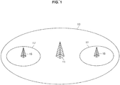
- a small cell is a cell smaller than a macro cell.
- the small cell partially or entirely overlaps the macro cell.
- an example of the small cell will be described with reference to FIG. 1 .
- a base station of LTE is referred to as an evolved node B (eNB).
- eNB evolved node B
- a macro base station of LTE is referred to as a macro eNB
- a small base station of LTE is referred to as a small eNB.
- a terminal device of LTE is referred to as user equipment (UE).
- UE user equipment
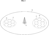
- Small cells arranged at a high density form a small cell cluster.
- an example of the small cell cluster will be described with reference to FIG. 2 .
- FIG. 2 is an explanatory diagram for describing an example of a small cell cluster.
- the macro base station 11, the macro cell 13 and the small cell 17 are shown.
- small cells 17 arranged at a high density form a small cell cluster 19.
- the small base station transmits a cell-specific reference signal (CRS) regardless of the presence or absence of traffic of the small cell.
- CRS cell-specific reference signal
- a CRS causes large interference in a neighbor cell. Therefore, various technologies for reducing interference are being studied.
- a small cell on/off technology As a technology for reducing such inter-cell interference, a small cell on/off technology has currently been focused on.
- an on/off state of a small cell is adaptively switched, and thus it is possible to suppress interference in a surrounding cell of the small cell.
- a trigger for switching an on/off state of the small cell has not yet been specifically decided, a trigger for switching based on, for example, a traffic amount, association of a terminal device, or arrival of a packet is being studied.
- FIG. 3 an example of a small cell on/off procedure will be described with reference to FIG. 3 .
- FIG. 3 is a sequence diagram illustrating an example of a schematic flow of a small cell on/off process.
- the small cell on/off process is a process that is disclosed in R1-134318 of the Third Generation Partnership Project (3GPP).
- 3GPP Third Generation Partnership Project
- the UE transmits an uplink signal to a macro eNB of a macro cell that is a serving cell (S1001).
- the macro eNB searches for a small eNB in an off state that is positioned around the UE, and instructs the appropriate small eNB to switch to an on state when there is an appropriate small eNB (S1003).
- the small eNB performs switching from the off state to the on state (S1005).
- the small eNB transmits downlink signals such as a primary synchronization signal (PSS), a secondary synchronization signal (SSS), a cell-specific reference signal (CRS) and a physical broadcast channel (PBCH) signal (S1007).
- PSS primary synchronization signal
- SSS secondary synchronization signal
- CRS cell-specific reference signal
- PBCH physical broadcast channel
- the UE performs a cell search and RRM measurement (S1009), and performs measurement reporting to the macro eNB (S1011).
- S1013 a handover of the UE from the macro cell to the small cell is performed.
- the UE and the small eNB perform an access procedure (S1015) and perform data transmission (S1017).
- a transition time may become relatively longer. That is, according to the procedure, a time from when a terminal device attempts to transmit data until the terminal device actually transmits the data may become relatively longer. Therefore, large improvement of throughput is difficult.
- a measurement process that serves as a main delay factor is preferably performed by the terminal device.
- the DRS enables measurement of a small cell in the off state.
- the DRS is also referred to as a discovery signal (DS).
- a small base station for example, a small eNB
- a terminal device for example, UE
- FIG. 4 an example of a small cell on/off procedure when a DRS is used will be described with reference to FIG. 4 .
- FIG. 4 is a sequence diagram illustrating an example of a schematic flow of a small cell on/off process when a DRS is used.
- the small cell on/off process is a process that is disclosed in R1-134318 of the 3GPP.
- a macro eNB instructs a small eNB to transmit a DS (S1031), and the small eNB transmits the DS in downlink (S1033).
- the UE performs measurement based on the DS (S1035) and reports a result of the measurement to the macro eNB (that is, an eNB of a macro cell that is a serving cell) (S1037).
- the UE and the small eNB perform data transmission through subsequent procedures (S1041 to S1049) (S1051).
- the terminal device can perform measurement. Therefore, the transition time is removed and throughput may be improved.
- a terminal device performs measurement based on a CRS transmitted by a base station. Specifically, the terminal device receives a CRS transmitted by a base station and thus performs measurement of quality of a propagation path between the base station and the terminal device.
- the measurement is referred to as “radio resource management (RRM) measurement,” or is simply referred to as “measurement.”
- a result of the measurement is used to select a cell for a terminal device.
- the result of the measurement is used for cell selection/cell reselection by a terminal device that is in a radio resource control (RRC) idle (RRC Idle) state.
- RRC radio resource control
- the result of the measurement is reported to a base station by a terminal device that is in an RRC connected state and is used for a handover decision by the base station.
- the RSRP is reception power of a CRS for each single resource element. That is, the RSRP is an average value of reception power of the CRS.
- the reception power of the CRS is obtained by detecting a correlation between a reception signal in a resource element of the CRS and a known signal CRS.
- the RSRP corresponds to a desired signal "Signal (S)."
- the RSSI is total power of signals for each Orthogonal Frequency Division Multiple Access (OFDMA) symbol. Therefore, the RSSI includes a desired signal, an interference signal and noise. That is, the RSSI corresponds to "Signal (S)+Interference (I)+Noise (N)."
- the RSRQ is RSRP/(RSRI/N).
- N denotes the number of resource blocks used for calculating an RSSI.
- the resource blocks are resource blocks that are arranged in a frequency direction. Therefore, the RSRQ is a value that is obtained by dividing the RSRP using the RSRI for each resource block. That is, the RSRQ corresponds to a signal-to-interference-plus-noise ratio (SINR).
- SINR signal-to-interference-plus-noise ratio
- reception power that is, RSRP
- reception quality that is, RSRQ
- Measurement of a frequency band that a terminal device uses is referred to as intra-frequency measurement. Conversely, measurement of a frequency band that a terminal device does not use is referred to as inter-frequency measurement.
- the terminal device can receive a CRS transmitted in a frequency band that is used without switching a frequency of a radio frequency (RF) circuit. That is, it is unnecessary to switch a frequency of the RF circuit for intra-frequency measurement.
- RF radio frequency
- the base station does not transmit a downlink signal addressed to a terminal device.
- the measurement gap is shared between the base station and the terminal device.
- the base station transmits a message (for example, an RRC connection reconfiguration message) including information indicating a measurement gap to the terminal device.
- the measurement gap is indicated by a measurement gap length (MGL), a measurement gap repetition period (MGRP) and a gap offset.
- MGL measurement gap length
- MGRP measurement gap repetition period
- a gap offset a combination of the MGL and the MGRP is determined as, for example, a gap pattern.
- FIG. 5 is an explanatory diagram for describing an example of a measurement gap.
- FIG. 5 shows a matrix including columns of radio frames whose SFNs are 0 to 9 and rows of 10 sub frames (subframes whose sub frame numbers are 0 to 9) included in radio frames.
- the MGL is 6 milliseconds (ms)
- the MGRP is 40 ms
- the gap offset is 0. Therefore, the measurement gap has a length of 6 ms and appears every 40 ms. More specifically, for example, six subframes whose subframe numbers are 0 to 5 among radio frames whose SFNs are 0, 4 and 8 are the measurement gap. Inter-frequency measurement is performed during the measurement gap.
- the terminal device reports a measurement result to the base station.
- the reporting is referred to as measurement reporting.
- the measurement reporting is periodic reporting or event-triggered reporting.
- the periodic reporting is reporting that is performed at set periods.
- the event-triggered reporting is reporting that is performed when a reporting event is generated.
- Reporting events A1 to A5 are events associated with a handover within a system
- reporting events B1 to B2 are events associated with a handover between systems.
- [Table 1] Event Type Description Event A1 Serving becomes better than threshold Event A2 Serving becomes worse than threshold Event A3 Neighbour becomes offset better than serving Event A4 Neighbour becomes better than threshold Event A5 Serving becomes worse than threshold1 and neighbour becomes better than threshold2
- Event B1 Inter RAT neighbour becomes better than threshold Event B2 Serving becomes worse than threshold1 and inter RAT neighbour becomes better than threshold2
- FIG. 6 to FIG. 8 are explanatory diagrams for describing first to third scenarios of carrier aggregation (CA).
- CA carrier aggregation
- inter-frequency measurements are performed at periods of 40 ms or 80 ms. That is, the inter-frequency measurement is frequently performed.
- improvement of inter-frequency measurement is being studied. For example, when a measurement period increases, a measurement frequency decreases. As a result, throughput and power consumption may be improved.
- the measurement is referred to as relax measurement.
- relax measurement is introduced into an environment in which an on/off state of a small cell is switched (hereinafter referred to as a "small cell on/off environment"), for example, a discovery of a small cell in the off state is delayed. This is because a base station of a small cell (that is, a small base station) in the off state periodically transmits a DRS.
- FIG. 9 is a first explanatory diagram for describing an example of measurement in a small cell on/off environment.
- the macro base station 11, the macro cell 13, the small base station 15, the small cell 17 and a terminal device 21 are shown.
- a small cell 17A and a small cell 17B are included in a small cell cluster 19A.
- a small cell 17C and a small cell 17D are included in a small cell cluster 19B.
- the terminal device 21 is connected to the macro base station 11.
- a CC0 is used by the macro base station 11. Therefore, a CRS is transmitted by the macro base station 11 in the CC0.
- the small cell 17A is in the on state.
- a CC1 is used by the small base station 15A in the small cell 17A. Therefore, in the CC1, a CRS is transmitted by the small base station 15A.
- the small cell 17B is in the off state and a CC2 is used by the small base station 15B in the small cell 17B. Therefore, a DRS is transmitted by the small base station 15B in the CC2.
- the small cell 17C is in the on state and a CC3 is used by the small base station 15C in the small cell 17C. Further, the small cell 17D is in the off state and a CC3 is used by the small base station 15D in the small cell 17D. Therefore, in the CC3, a CRS is transmitted by the small base station 15C and a DRS is transmitted by the small base station 15D.
- FIG. 10 is a second explanatory diagram for describing an example of measurement in a small cell on/off environment.
- a CRS is transmitted in a CC0
- a CRS is transmitted in a CC1
- a DRS is transmitted in a CC2
- a CRS and a DRS are transmitted in a CC3 identically to those described with reference to FIG. 9 .
- the terminal device 21 performs intra-frequency measurement of the CC0.
- the terminal device 21 performs inter-frequency measurement of the CC1, CC2 and the CC3 using a measurement gap having a period of 40 ms or 80 ms.
- an inter-frequency measurement frequency may increase when the number of CCs increases.
- an inter-frequency measurement frequency may increase regardless of an on/off state of the small cell.
- an inter-frequency measurement frequency is maintained and, as a result, inter-frequency measurement may consume much time.
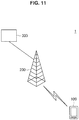
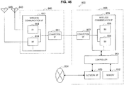
- FIG. 11 is an explanatory diagram illustrating an example of a schematic configuration of the communication system 1 according to an embodiment of the present disclosure.
- the communication system 1 includes a terminal device 100, a base station 200 and a control entity 300.
- the communication system 1 is a system supporting, for example, LTE, LTE-Advanced or a communication standard equivalent thereto.
- the terminal device 100 wirelessly communicates with the base station 200. In addition, the terminal device 100 performs measurement of each frequency band that is used by the base station. In addition, the terminal device 100 reports a result of the measurement to the base station 200.
- the base station 200 wirelessly communicates with one or more terminal devices including the terminal device 100.
- the base station 200 may be a base station of a macro cell (that is, a macro base station) or a base station of a small cell (that is, a small base station).
- the control entity 300 performs control according to each embodiment of the present disclosure.
- the control entity 300 is, for example, an existing or new core network node.
- the control entity 300 may be a macro base station.
- a terminal device 100-1 performs measurement of each of one or more frequency bands that are a part of a plurality of frequency bands that are not used by the terminal device 100-1. Specifically, according to the first embodiment, the terminal device 100-1 does not perform measurement of each of the remaining frequency bands among the plurality of frequency bands or performs the measurement of each of the remaining frequency bands at a frequency lower than a frequency of the measurements of each of the one or more frequency bands. Accordingly, for example, it is possible to improve measurement performed by the terminal device 100-1. As a specific example, a measurement load on the terminal device 100-1 may be reduced.
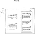
- FIG. 12 is a block diagram illustrating an example of a configuration of the terminal device 100-1 according to the first embodiment.
- the terminal device 100-1 includes an antenna unit 110, a wireless communication unit 120, a storage unit 130 and a processing unit 140.
- the antenna unit 110 emits a signal output by the wireless communication unit 120 into space as radio waves.
- the antenna unit 110 converts spatial radio waves into a signal and outputs the signal to the wireless communication unit 120.
- the wireless communication unit 120 transmits and receives signals. For example, the wireless communication unit 120 receives a downlink signal from a base station and transmits an uplink signal to the base station.
- the storage unit 130 temporarily or permanently stores programs and data for operations of the terminal device 100-1.
- the processing unit 140 provides various functions of the terminal device 100-1.
- the processing unit 140 includes an information acquiring unit 141, a measurement unit 143 and a reporting unit 145.
- the processing unit 140 may further include a component other than these components. That is, the processing unit 140 may also perform an operation other than operations of these components.
- the information acquiring unit 141 acquires information about a frequency band.
- the information acquiring unit 141 acquires a measurement configuration of a frequency band.
- a base station 200-1 transmits an RRC connection reconfiguration message including the measurement configuration to the terminal device 100-1, and the information acquiring unit 141 acquires the measurement configuration.
- the measurement configuration includes information such as measurement objects, reporting configurations, measurement identities (measurement IDs) and measurement gaps.
- the information acquiring unit 141 acquires a neighboring cell list (NCL).
- NCL neighboring cell list
- the information acquiring unit 141 acquires an intra-frequency NCL and an inter-frequency NCL.
- the base station 200-1 informs the information acquiring unit 141 of an intra-frequency NCL within a system information block (SIB) 4, and the information acquiring unit 141 acquires the intra-frequency NCL.
- SIB system information block
- the base station 200-1 informs the information acquiring unit 141 of an inter-frequency NCL within an SIB5, and the information acquiring unit 141 acquires the inter-frequency NCL.
- the measurement unit 143 performs measurement of a frequency band.
- the measurement unit 143 performs measurement of each of one or more frequency bands that are a part of a plurality of frequency bands that are not used by the terminal device 100-1. Conversely, the measurement unit 143 does not perform measurement of each of the remaining frequency bands among the plurality of frequency bands or performs the measurement of each of the remaining frequency bands at a frequency lower than a frequency of the measurements of each of the one or more frequency bands. Accordingly, for example, it is possible to improve measurement performed by the terminal device 100-1.
- each of the plurality of frequency bands is a component carrier (CC) of carrier aggregation.
- CC component carrier
- the remaining frequency bands are frequency bands included in the same operating band as the one or more frequency bands. That is, the plurality of frequency bands are included in a single operating band.
- the terminal device 100-1 can use the frequency band with a high probability while reducing a measurement load.
- each of the remaining frequency bands is a frequency band adjacent to any frequency band included in the one or more frequency bands.
- the terminal device 100-1 can use the frequency band with a fairly high probability while reducing a measurement load.
- each of the plurality of frequency bands is a frequency band that is used by a base station of a small cell.
- the plurality of frequency bands have been described above.
- the first embodiment is not limited thereto.
- the plurality of frequency bands may include frequency bands included in a different operating band.
- the plurality of frequency bands may include a frequency band that is used only by a macro base station.
- the measurement of each of the one or more frequency bands is measurement based on a reference signal transmitted in each of the one or more frequency bands.
- the measurement of each of the remaining frequency bands is measurement based on a reference signal transmitted in each of the remaining frequency bands.
- the reference signal is a cell-specific reference signal (CRS). Accordingly, for example, it is possible to reduce a measurement load regarding a small cell in the on state. A measurement load regarding a macro cell may also be reduced.
- CRS cell-specific reference signal
- the measurement of each of the one or more frequency bands is RRM measurement.
- the measurement of each of the one or more frequency bands is measurement of reception power or reception quality. More specifically, for example, the measurement of each of the one or more frequency bands is measurement of RSRP or RSRQ.
- the measurement of each of the one or more frequency bands is performed for each cell in which each of the one or more frequency bands is used (that is, a base station that uses each of the one or more frequency bands).
- the measurement unit 143 does not perform the measurement of each of the remaining frequency bands.
- this will be described with reference to a specific example of FIG. 13 .
- FIG. 13 is an explanatory diagram for describing a first example of measurement according to the first embodiment.
- a CRS is transmitted in a CC0 and a CC1.
- the terminal device 100-1 performs inter-frequency measurement of the CC0.
- inter-frequency measurement of the CC1 is not performed.
- a frequency band that is a measurement (that is, inter-frequency measurement) target is limited. Therefore, it is possible to further decrease a frequency of measurements performed by the terminal device 100-1. As a result, a load of measurements performed by the terminal device 100-1 may be reduced. In addition, power consumption of the terminal device 100-1 may decrease and throughput may be improved. Alternatively, measurement of a specific frequency band can be intensively performed for a short period. As a result, measurement of the specific frequency band may be performed more quickly.
- the measurement unit 143 performs the measurement of each of the remaining frequency bands at a frequency lower than a frequency of the measurements of each of the one or more frequency bands.
- the measurement unit 143 performs the measurement of each of the remaining frequency bands using fewer measurement gaps than measurement gaps used for the measurement of each of the one or more frequency bands.
- the measurement unit 143 skips a part of the measurement gaps assigned to each of the remaining frequency bands without measurement.
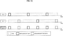
- this will be described with reference to a specific example of FIG. 14 .
- FIG. 14 is an explanatory diagram for describing a second example of measurement according to the first embodiment.
- a CRS is transmitted in a CC0 and a CC1.
- the same number of measurement gaps is assigned to the CC0 and CC1.
- the terminal device 100-1 performs measurement of the CC0 using all measurement gaps assigned to the CC0.
- the terminal device 100-1 skips a part of all measurement gaps assigned to the CC1 without measurement of the CC1, and performs measurement of the CC1 using the rest of the all measurement gaps assigned to the CC1.
- a frequency of measurements performed by the terminal device 100-1 decreases.
- a load of measurements performed by the terminal device 100-1 may be reduced.
- power consumption of the terminal device 100-1 may decrease and throughput may be improved.
- measurement gaps assigned to each of the remaining frequency bands may be fewer than measurement gaps assigned to each of the one or more frequency bands.
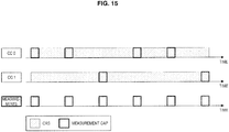
- this will be described with reference to a specific example of FIG. 15 .
- FIG. 15 is an explanatory diagram for describing a third example of measurement according to the first embodiment.
- a CRS is transmitted in a CC0 and a CC1.
- more measurement gaps are assigned to the CC0 and fewer measurement gaps are assigned to the CC1.
- the terminal device 100-1 performs measurement of the CC0 using the more measurement gaps assigned to the CC0, and performs measurement of the CC1 using the fewer measurement gaps assigned to the CC 1.
- measurement of a specific frequency band can be intensively performed for a short period.
- measurement of the specific frequency band may be performed more quickly.
- the measurement of each of the remaining frequency bands is RRM measurement.
- the measurement of each of the remaining frequency bands is measurement of reception power or reception quality. More specifically, for example, the measurement of each of the remaining frequency bands is measurement of RSRP or RSRQ.
- the measurement of each of the remaining frequency bands is performed for each cell in which each of the remaining frequency bands is used (that is, a base station that uses each of the remaining frequency bands).
- the measurement by the measurement unit 143 is performed according to an instruction from the base station 200-1. That is, the terminal device 100-1 performs the measurement by the measurement unit 143 according to an instruction from the base station 200-1.
- the measurement by the measurement unit 143 may be voluntarily performed. That is, the terminal device 100-1 may voluntarily perform the measurement by the measurement unit 143. In this case, the base station 200-1 may not perform some or all of operations which will be described.
- the reporting unit 145 reports a result of the measurement of a frequency band to the base station 200-1.
- the reporting unit 145 reports a result of the measurement of each of the one or more frequency bands to the base station 200-1.
- the measurement unit 143 does not perform the measurement of each of the remaining frequency bands.
- the reporting unit 145 does not report a result of the measurement of each of the remaining frequency bands to the base station 200-1.
- the reporting unit 145 may substitute a result of measurement of a first frequency band included in the one or more frequency bands with a result of measurement of a second frequency band included in the remaining frequency bands, and thus may report the result of the measurement of the second frequency band to the base station 200-1. Accordingly, for example, a frequency band that is not actually measured may be selected as a frequency band that is used by the terminal device 100-1.
- the measurement unit 143 performs the measurement of each of the remaining frequency bands at a frequency lower than a frequency of the measurements of each of the one or more frequency bands.
- the reporting unit 145 reports a result of the measurement of each of the remaining frequency bands to the base station 200-1.
- the reporting unit 145 reports a result of measurement to the base station 200-1 according to a reporting configuration included in the measurement configuration from the base station 200-1.
- the reporting unit 145 reports the result of the measurement to the base station 200-1 through the antenna unit 110 and the wireless communication unit 120.
- FIG. 16 is a block diagram illustrating an example of a configuration of the base station 200-1 according to the first embodiment.
- the base station 200-1 includes an antenna unit 210, a wireless communication unit 220, a network communication unit 230, a storage unit 240, and a processing unit 250.
- the antenna unit 210 radiates a signal output from the wireless communication unit 220 into the air as radio waves.
- the antenna unit 210 converts the radio waves in the air into a signal, and outputs the signal to the wireless communication unit 220.
- the wireless communication unit 220 transmits or receives a signal.
- the wireless communication unit 220 transmits the downlink signal to the terminal device, and receives the uplink signal from the terminal device.
- the network communication unit 230 communicates with other nodes.
- the network communication unit 230 communicates with a core network node and other base stations.
- the network communication unit 230 communicates with a control entity 300-1.
- the storage unit 240 temporarily or permanently stores a program and data for an operation of the base station 200-1.
- the processing unit 250 provides various functions of the base station 200-1.
- the processing unit 250 includes an information acquiring unit 251 and a control unit 253.
- the processing unit 250 may further include any other component in addition to the above-mentioned components. In other words, the processing unit 250 may also perform an operation other than operations of the above-mentioned components.
- the information acquiring unit 251 acquires information about a plurality of frequency bands that are not used by the terminal device 100-1.
- the information about the plurality of frequency bands includes information indicating each of the plurality of frequency bands (for example, a downlink carrier frequency or identification information).
- the control unit 253 instructs the terminal device 100-1 to perform measurement of each of one or more frequency bands that are a part of the plurality of frequency bands, and not to perform measurement of each of the remaining frequency bands among the plurality of frequency bands or perform the measurement of each of the remaining frequency bands at a frequency lower than a frequency of the measurements of each of the one or more frequency bands.
- control unit 253 selects the one or more frequency bands from among the plurality of frequency bands.
- control unit 253 may select the remaining frequency bands other than the one or more frequency bands from among the plurality of frequency bands.
- control unit 253 instructs the terminal device 100-1 to perform the measurement of each of the one or more frequency bands and not to perform measurement of each of the remaining frequency bands among the plurality of frequency bands.
- the control unit 253 may substitute a result of measurement of a first frequency band included in the one or more frequency bands with a result of measurement of a second frequency band included in the remaining frequency bands.
- the control unit 253 substitutes a result of measurement of the first frequency band with a result of measurement of the second frequency band and thus may perform a handover decision.
- the second frequency band may be a frequency band that is adjacent to the first frequency band. Accordingly, for example, a frequency band that is not actually measured may be selected as a frequency band that is used by the terminal device 100-1.
- control unit 253 instructs the terminal device 100-1 to perform the measurement of each of the remaining frequency bands at a frequency lower than a frequency of the measurements of each of the one or more frequency bands.
- control unit 253 instructs the terminal device 100-1 to perform the measurement of each of the remaining frequency bands using fewer measurement gaps than measurement gaps used for the measurement of each of the one or more frequency bands.
- control unit 253 instructs the terminal device 100-1 to skip a part of measurement gaps assigned to each of the remaining frequency bands without measurement.
- control unit 253 may instruct the terminal device 100-1 to assign fewer measurement gaps to each of the remaining frequency bands than to each of the one or more frequency bands.
- control unit 253 may decide measurement gap assignment such that the measurement gaps assigned to each of the remaining frequency bands are fewer than measurement gaps assigned to each of the one or more frequency bands.
- the control unit 253 may instruct the terminal device 100-1 to perform the decided assignment.
- control unit 253 performs an instruction according to individual signaling to the terminal device 100-1.
- the individual signaling is RRC signaling.
- control unit 253 may transmit an RRC connection reconfiguration message including a measurement configuration through the antenna unit 210 and the wireless communication unit 220, and thus may perform the instruction.
- FIG. 17 is a sequence diagram illustrating a first example of a schematic flow of a process according to the first embodiment.
- the base station 200-1 acquires information about a plurality of frequency bands that are not used by the terminal device 100-1 (S401).
- the base station 200-1 instructs the terminal device 100-1 to perform measurement of each of one or more frequency bands that are a part of the plurality of frequency bands and not to perform measurement of each of the remaining frequency bands among the plurality of frequency bands (S403).
- the terminal device 100-1 (the measurement unit 143) performs measurement of each of the one or more frequency bands (S405).
- the terminal device 100-1 (the measurement unit 143) does not perform measurement of each of the remaining frequency bands.
- the terminal device 100-1 (the reporting unit 145) reports a result of the measurement to the base station 200-1 (S407).
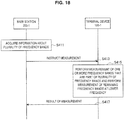
- FIG. 18 is a sequence diagram illustrating a second example of a schematic flow of a process according to the first embodiment.
- the base station 200-1 acquires information about a plurality of frequency bands that are not used by the terminal device 100-1 (S411).
- the base station 200-1 instructs the terminal device 100-1 to perform measurement of each of one or more frequency bands that are a part of the plurality of frequency bands and perform measurement of each of the remaining frequency bands among the plurality of frequency bands at a frequency lower than a frequency of the measurements of each of the one or more frequency bands (S413).
- the terminal device 100-1 (the measurement unit 143) performs measurement of each of the one or more frequency bands, and performs the measurement of each of the remaining frequency bands at a frequency lower than a frequency of the measurements of each of the one or more frequency bands (S415).
- the terminal device 100-1 (the reporting unit 145) reports a result of the measurement to the base station 200-1 (S417).
- the measurement of each of the one or more frequency bands is measurement based on a reference signal transmitted in each of the one or more frequency bands.
- the measurement of each of the remaining frequency bands is measurement based on a reference signal transmitted in each of the remaining frequency bands.
- the reference signal is a CRS.
- the reference signal is a discovery reference signal (DRS).
- the measurement of each of the one or more frequency bands is measurement based on a reference signal transmitted in each of the one or more frequency bands.
- the measurement of each of the remaining frequency bands is measurement based on a reference signal transmitted in each of the remaining frequency bands.
- the reference signal is a discovery reference signal (DRS). Accordingly, for example, it is possible to reduce a measurement load regarding a small cell in the off state.
- DRS discovery reference signal
- the DRS is a reference signal that is transmitted by a base station of the small cell in an off state.
- the DRS may also be referred to as a discovery signal (DR).
- DR discovery signal
- the measurement unit 143 does not perform the measurement of each of the remaining frequency bands.
- this will be described with reference to a specific example of FIG. 19 .
- FIG. 19 is an explanatory diagram for describing a first example of measurement according to a modification example of the first embodiment.
- a DRS is transmitted in a CC0 and a CC1.
- inter-frequency measurement of the CC0 is performed in the terminal device 100-1.
- inter-frequency measurement of the CC1 is not performed.
- the measurement unit 143 performs the measurement of each of the remaining frequency bands at a frequency lower than a frequency of the measurements of each of the one or more frequency bands.
- the measurement unit 143 skips a part of measurement gaps assigned to each of the remaining frequency bands without measurement.
- this will be described with reference to a specific example of FIG. 20 .
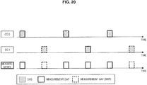
- FIG. 20 is an explanatory diagram for describing a second example of measurement according to a modification example of the first embodiment.
- a DRS is transmitted in a CC0 and a CC1.
- the same number of measurement gaps is assigned to the CC0 and the CC1.
- the terminal device 100-1 performs measurement of the CC0 using all measurement gaps assigned to the CC0.
- the terminal device 100-1 skips a part of all measurement gaps assigned to the CC1 without measurement of the CC1 and performs measurement of the CC1 using the rest of the all measurement gaps assigned to the CC 1.
- measurement gaps assigned to each of the remaining frequency bands may be fewer than measurement gaps assigned to each of the one or more frequency bands.
- this will be described with reference to a specific example of FIG. 21 .
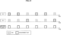
- FIG. 21 is an explanatory diagram for describing a third example of measurement according to a modification example of the first embodiment.
- a DRS is transmitted in a CC0 and a CC1.
- more measurement gaps are assigned to the CC0 and fewer measurement gaps are assigned to the CC1.
- the terminal device 100-1 performs measurement of the CC0 using the more measurement gaps assigned to the CC0, and performs measurement of the CC1 using the fewer measurement gaps assigned to the CC1.
- a terminal device 100-2 performs measurement of a first frequency band based on a discovery reference signal transmitted in the first frequency band within a first period included in a measurement gap, and performs measurement of a second frequency band based on a reference signal transmitted in the second frequency band within a second period included in the measurement gap.
- the reference signal transmitted in the second frequency band is a DRS. That is, in the second embodiment, the terminal device 100-2 performs measurement of a frequency group including the first frequency band and the second frequency band using the measurement gap. Accordingly, for example, it is possible to improve measurement performed by a terminal device 100-3.
- FIG. 22 is a block diagram illustrating an example of a configuration of the terminal device 100-2 according to the second embodiment.
- the terminal device 100-2 includes the antenna unit 110, the wireless communication unit 120, the storage unit 130 and a processing unit 150.
- the processing unit 150 provides various functions of the terminal device 100-2.
- the processing unit 150 includes an information acquiring unit 151, a measurement unit 153 and a reporting unit 155.
- the processing unit 150 may further include a component other than these components. That is, the processing unit 150 may also perform an operation other than operations of these components.
- the information acquiring unit 151 acquires information indicating a first frequency band in which a DRS is transmitted within at least a first period included in a measurement gap. Specifically, in the second embodiment, the information acquiring unit 151 acquires information indicating a frequency group including the first frequency band and a second frequency band.
- the second frequency band is a frequency band in which a DRS is transmitted within at least a second period included in the measurement gap.
- a base station 200-2 notifies the terminal device 100-2 of the frequency group and the measurement gap.
- the base station 200-2 transmits information indicating the frequency group and information indicating the measurement gap to the terminal device 100-2.
- the base station 200-2 transmits an RRC connection reconfiguration message including a measurement configuration including the information indicating the frequency group and the information indicating the measurement gap to the terminal device 100-2.
- the information acquiring unit 151 acquires the information indicating the frequency group and the information indicating the measurement gap.
- the measurement unit 153 performs measurement of a frequency band.
- the measurement unit 153 performs measurement of a first frequency band based on a DRS transmitted in the first frequency band within a first period included in a measurement gap. In addition, the measurement unit 153 performs measurement of a second frequency band based on a reference signal transmitted in the second frequency band within a second period included in the measurement gap. Accordingly, for example, it is possible to improve measurement performed by the terminal device 100-3.
- the first frequency band and the second frequency band each are component carriers (CCs) of carrier aggregation.
- CCs component carriers
- each of the first frequency band and the second frequency band is a frequency band that is used by a base station of a small cell.
- each of the first frequency band and the second frequency band is a frequency band that is not used by the terminal device 100-2.
- each of the first frequency band and the second frequency band is a CC that is used by a base station of a small cell, and the CC is not used by the terminal device 100-2.
- the measurement of the first frequency band and the measurement of the second frequency band are RRM measurements, for example, measurements of reception power or reception quality.
- the measurement of the first frequency band and the measurement of the second frequency band are measurements of RSRP or RSRQ.
- measurement is performed in units of a combination of a frequency band and a cell (a base station).
- the measurement of the first frequency band is performed for each cell in which the first frequency band is used (that is, a base station that uses the first frequency band).
- the measurement of the second frequency band is performed for each cell in which the second frequency band is used (that is, a base station that uses the second frequency band).
- the reference signal transmitted in the second frequency band is a DRS. That is, the measurement unit 153 performs measurement of the first frequency band and the second frequency band in which a DRS is transmitted using the measurement gap.
- the measurement gap is a period having a length of 6 milliseconds. That is, the measurement gap is a general measurement gap.
- each of the first period and the second period is a period shorter than 6 milliseconds. That is, a shorter period is used for measurement based on a DRS than general measurement based on a CRS.
- measurement gap When measurement of the first frequency band and measurement of the second frequency band are collectively performed using the measurement gap, for example, it is possible to perform measurement of the first frequency band and measurement of the second frequency band using fewer measurement gaps. Therefore, measurement based on a DRS (that is, inter-frequency measurement of a frequency band that is used by a base station of a small cell) may be efficiently performed. As a specific example, measurement based on a DRS may be performed more quickly.
- a DRS that is, inter-frequency measurement of a frequency band that is used by a base station of a small cell
- the measurement gap may include an additional period.
- the measurement unit 153 may perform measurement of an additional frequency band based on a DRS transmitted in the additional frequency band within the additional period.
- this will be described with reference to a specific example of FIG. 24 .
- FIG. 24 is an explanatory diagram for describing a second example of measurement according to the second embodiment.
- a measurement gap having a length of 6 subframes is shown.
- the measurement unit 153 performs measurement of a CC1 based on a DRS transmitted in the CC1 (a first frequency band) within a period (a first period) including a 1st subframe and a 2nd subframe within the measurement gap.
- the measurement unit 153 performs measurement of a CC2 based on a DRS transmitted in the CC2 (a second frequency band) within a period (a second period) including a 3rd subframe and a 4th subframe within the measurement gap.
- the measurement unit 153 performs measurement of a CC3 based on a DRS transmitted in the CC3 (an additional frequency band) within a period (an additional period) including a 5th sub frame and a 6th sub frame within the measurement gap.
- measurement based on a DRS (that is, inter-frequency measurement) may be further efficiently performed.
- the second embodiment is not limited thereto.
- the measurement gap may include two or more additional periods and the measurement unit 153 may perform measurement of two or more additional frequency bands.
- a base station of a small cell in the on state transmits both a DRS and a CRS in the first frequency band.
- the measurement unit 153 may perform measurement of the first frequency band that is used by the base station based on the DRS and the CRS transmitted by the base station in the first frequency band within the first period.
- this will be described with reference to a specific example of FIG. 25 .
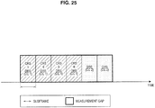
- FIG. 25 is an explanatory diagram for describing a third example of measurement according to the second embodiment.
- a measurement gap having a length of 6 subframes is shown.
- the measurement unit 153 performs measurement of a CC1 based on a DRS and a CRS transmitted by the same base station using the CC1 (a first frequency band) within a period (a first period) from a 1st subframe to a 4th subframe within the measurement gap.
- the measurement unit 153 performs measurement of a CC2 based on a DRS transmitted in the CC2 (a second frequency band) within a period (a second period) including a 5th subframe and a 6th subframe within the measurement gap.
- measurement of the first frequency band or the second frequency band is performed based on more reference signals. Therefore, the measurement of the first frequency band or the second frequency band used by the base station may be performed using a shorter period than when it is performed based on only a CRS. Therefore, measurement of the first frequency band and measurement of the second frequency band (that is, measurement of a frequency band that is used by a base station of a small cell in the on state and measurement of a frequency band that is used by a base station of another small cell) may be performed using the same measurement gap.
- the measurement unit 153 performs measurement of a frequency group and measurement of one or more other frequency bands or measurement of one or more other frequency groups based on a priority of the frequency group including the first frequency band and the second frequency band and a priority of the one or more other frequency bands or a priority of the one or more other frequency groups.
- a frequency group or a frequency band having a higher priority is sequentially selected from among the frequency group including the first frequency band and the second frequency band, the one or more other frequency bands, and the one or more other frequency groups. Then, the measurement unit 153 performs measurement of the selected frequency group or frequency band.
- the priority of the frequency group (and/or a priority of each of the one or more other frequency groups) may be decided in consideration of power consumption and/or a communication request of the terminal device 100-2.
- the priority of the frequency group may be higher. This is because, when the priority of the frequency group is high, measurement of more frequency bands is performed using a measurement gap.
- the priority of the frequency group may be lower. This is because, when the priority of the frequency group is low, measurement of a frequency band that is used by a base station of a cell in the on state is preferentially performed, and, as a result, a handover is preferentially performed without a transition time.
- the measurement unit 153 performs the measurement of the frequency group, and the measurement of the one or more other frequency bands or the measurement of the one or more other frequency groups in consideration of a transmission period in which a DRS is transmitted in the first frequency band.
- the measurement unit 153 performs measurement of another frequency band or another frequency group whose priority is lower than the frequency group before the measurement of the frequency group outside of the transmission period.
- measurement may be performed more smoothly without wasting the measurement gap.
- the reporting unit 155 reports a result of measurement of the frequency band to the base station 200-2.
- the reporting unit 155 reports a result of measurement of the first frequency band to the base station 200-2.
- the reporting unit 155 reports a result of measurement of the second frequency band to the base station 200-2.
- the frequency group may include an additional frequency band, and the reporting unit 155 may report a result of measurement of the additional frequency band to the base station 200-2.
- FIG. 26 is a block diagram illustrating an example of a configuration of the base station 200-2 according to the second embodiment.
- the base station 200-2 includes an antenna unit 210, a wireless communication unit 220, a network communication unit 230, a storage unit 240, and a processing unit 260.
- the processing unit 260 provides various functions of the base station 200-2.
- the processing unit 260 includes an information acquiring unit 261 and a control unit 263.
- the processing unit 260 may further include any other component in addition to the above-mentioned components. In other words, the processing unit 260 may also perform an operation other than operations of the above-mentioned components.
- the information acquiring unit 261 acquires information indicating a first frequency band in which a DRS is transmitted within at least a first period included in a measurement gap.
- the measurement gap further includes a second period in which a reference signal is transmitted in a second frequency band.
- the information acquiring unit 261 acquires information indicating the frequency group including the first frequency band and the second frequency band.
- the second frequency band is a frequency band in which a DRS is transmitted within at least a second period included in the measurement gap.
- a control entity 300-2 decides the frequency group and notifies the base station 200-2 of the frequency group. Then, the information indicating the frequency group is stored in the storage unit 240. The information acquiring unit 261 acquires the information indicating the frequency group at any time thereafter.
- the information acquiring unit 261 acquires information indicating the measurement gap.
- control entity 300-2 decides the measurement gap and notifies the base station 200-2 of the measurement gap. Then, information indicating the measurement gap is stored in the storage unit 240. The information acquiring unit 261 acquires the information indicating the measurement gap at any time thereafter.
- the measurement gap is decided by a device other than the control entity 300-2 and the base station 200-2 may be notified thereof.
- the measurement gap is decided by the base station 200-2, and may be stored in the storage unit 240.
- the control unit 263 notifies the terminal device 100-2 of the first frequency band and the measurement gap. Specifically, in the second embodiment, the control unit 263 notifies the terminal device 100-2 of the frequency group including the first frequency band and the second frequency band and the measurement gap.
- control unit 263 transmits information indicating the frequency group and information indicating the measurement gap to the terminal device 100-2 through the antenna unit 210 and the wireless communication unit 220.
- control unit 263 transmits an RRC connection reconfiguration message including a measurement configuration including the information indicating the frequency group and the information indicating the measurement gap to the terminal device 100-2 through the antenna unit 210 and the wireless communication unit 220.
- control unit 263 notifies the terminal device 100-2 of a priority of the frequency group and a priority of one or more other frequency bands or a priority of one or more other frequency groups.
- control unit 263 transmits information indicating the priority of the frequency group and the priority of one or more other frequency bands or the priority of one or more other frequency groups to the terminal device 100-2 through the antenna unit 210 and the wireless communication unit 220.
- the information is included in the inter-frequency NCL within the SIB5, and the control unit 263 informs the terminal device 100-2 of the SIB5 including the inter-frequency NCL through the antenna unit 210 and the wireless communication unit 220.
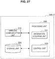
- FIG. 27 is a block diagram illustrating an example of a configuration of the control entity 300-2 according to the second embodiment.
- the control entity 300-2 includes a communication unit 310, a storage unit 320, and a processing unit 330.
- the communication unit 310 communicates with other nodes.
- the communication unit 310 communicates with a core network node and a base station.
- the communication unit 310 communicates with the base station 200-2.
- the storage unit 320 temporarily or permanently stores a program and data for an operation of the control entity 300-2.
- the processing unit 330 provides various functions of the control entity 300-2.
- the processing unit 330 includes an information acquiring unit 331 and a control unit 333.
- the processing unit 330 may further include any other component in addition to the above-mentioned components. In other words, the processing unit 330 may also perform an operation other than operations of the above-mentioned components.
- the information acquiring unit 331 acquires information about two or more frequency bands in which a DRS is transmitted.
- Each of the two or more frequency bands is a frequency band that is used by a base station of a small cell.
- a base station of a small cell in the off state transmits a DRS and a base station of a small cell in the on state does not transmit a DRS
- each of the two or more frequency bands is a frequency band that is used by the base station of the small cell in the off state.
- a base station of a small cell transmits a DRS regardless of an on/off state
- each of the two or more frequency bands is a frequency band that is used by the base station of the small cell.
- the control unit 333 decides a frequency group including at least a first frequency band and a second frequency band among the two or more frequency bands.
- the first frequency band is a frequency band in which a DRS is transmitted within at least a first period included in a measurement gap.
- the second frequency band is a frequency band in which a DRS is transmitted within at least a second period included in the measurement gap.
- control unit 333 decides the measurement gap.
- the control unit 333 controls a transmission period in which a DRS is transmitted in a first frequency band such that the DRS is transmitted in the first frequency band within at least the first period or controls a transmission period in which a DRS is transmitted in a second frequency band such that the DRS is transmitted in the second frequency band within at least the second period.
- the control unit 333 decides a frequency group including at least the first frequency band and the second frequency band among the two or more frequency bands.
- the frequency group is any frequency band among the two or more frequency bands and the number thereof is equal to or less than a predetermined maximum number.
- the predetermined maximum number is M/N (for example, 2). Further, the control unit 333 decides the measurement gap.
- the control unit 333 instructs a base station that transmits a DRS in each of the frequency bands included in the frequency group to transmit the DRS during the measurement gap. For example, the control unit 333 instructs a base station that transmits a DRS in the first frequency band and a base station that transmits a DRS in the second frequency band to transmit the DRSs during the measurement gap.
- the information about the two or more frequency bands may include information indicating a transmission period in which a DRS is transmitted in each of the two or more frequency bands. Then, the control unit 333 may decide the frequency group based on the transmission period.
- the control unit 333 decides at least two frequency bands whose transmission periods of the DRSs are the same (or similar) among the two or more frequency bands as a frequency group.
- the control unit 333 decides frequency bands whose number is equal to or less than a predetermined maximum number as a frequency group.
- the control unit 333 decides a measurement gap that overlaps the transmission period of the DRS.
- control unit 333 notifies the base station 200-2 of the frequency group. In addition, for example, the control unit 333 notifies the base station 200-2 of the measurement gap.
- control unit 333 transmits a message including information indicating the frequency group and information indicating the measurement gap to the base station 200-2 through the communication unit 310.
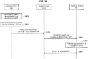
- FIG. 28 is a sequence diagram illustrating an example of a schematic flow of a process according to the second embodiment.
- the control entity 300-2 performs a frequency group decision process (S430). That is, the control entity 300-2 (the control unit 333) decides a frequency group including at least a first frequency band and a second frequency band among two or more frequency bands in which a DRS is transmitted. In addition, for example, the control entity 300-2 decides a measurement gap that is used for measurement of the frequency group.
- S430 a frequency group decision process
- control entity 300-2 notifies the base station 200-2 of the frequency group and the measurement gap (S451).
- the base station 200-2 notifies the terminal device 100-2 of the frequency group and the measurement gap (S453).
- the terminal device 100-2 performs measurement of the frequency group (S455). Specifically, the measurement unit 153 performs measurement of the first frequency band based on a DRS transmitted in the first frequency band within a first period included in the measurement gap. In addition, the measurement unit 153 performs measurement of the second frequency band based on a reference signal transmitted in the second frequency band within a second period included in the measurement gap.
- the terminal device 100-2 (the reporting unit 155) reports a result of measurement of the frequency band to the base station 200-2 (S457).
- FIG. 29 is a sequence diagram illustrating a first example of a schematic flow of a frequency group decision process according to the second embodiment.
- the processing unit 330 determines whether two or more frequency bands in which a DRS is transmitted exist (5431). When two or more frequency bands do not exist (NO in 5431), the process ends.
- the information acquiring unit 331 acquires information about the two or more frequency bands in which a DRS is transmitted (S433).
- control unit 333 decides a frequency group including at least a first frequency band and a second frequency band among the two or more frequency bands (S435).
- control unit 333 decides a measurement gap (S437).
- the control unit 333 controls a transmission period in which a DRS is transmitted in the first frequency band such that the DRS is transmitted in the first frequency band within at least a first period included in the measurement gap (S438).
- the control unit 333 instructs a base station that transmits a DRS in the first frequency band to transmit the DRS during the measurement gap.
- control unit 333 controls a transmission period in which a DRS is transmitted in the second frequency band such that the DRS is transmitted in the second frequency band within at least a second period included in the measurement gap (S439).
- control unit 333 instructs a base station that transmits a DRS in the second frequency band to transmit the DRS during the measurement gap. Then, the process ends.
- FIG. 30 is a sequence diagram illustrating a second example of a schematic flow of a frequency group decision process according to the second embodiment.
- the processing unit 330 determines whether two or more frequency bands in which a DRS is transmitted exist (S441). When two or more frequency bands do not exist (NO in S441), the process ends.
- the information acquiring unit 331 acquires information about the two or more frequency bands in which a DRS is transmitted (S443).
- the information about the two or more frequency bands includes information indicating a transmission period in which a DRS is transmitted in each of the two or more frequency bands.
- control unit 333 determines whether at least two frequency bands whose transmission periods of a DRS are the same (or similar) are included in the two or more frequency bands (S445). When the at least two frequency bands are not included (NO in S445), the process ends.
- the control unit 333 decides a frequency group including at least two frequency bands (at least a first frequency band and a second frequency band) whose transmission periods of a DRS are the same (or similar) among the two or more frequency bands (S447).
- control unit 333 decides a measurement gap that overlaps the transmission period of the DRS (S449). Then, the process ends.
- the base station 200-2 decides the frequency group (and the measurement gap) instead of the control entity 300-2. Then, the base station 200-2 notifies the terminal device 100-2 of the frequency group (and the measurement gap) it decided.
- the processing unit 260 of the base station 200-2 further includes the information acquiring unit 331 and the control unit 333.
- the terminal device 100-2 decides the frequency group (and the measurement gap) instead of the control entity 300-2. Then, the base station 200-2 performs measurement of the frequency group it decided.
- Terminal device 100-2 processing unit 150
- the processing unit 150 decides a frequency group including at least a first frequency band and a second frequency band among two or more frequency bands in which a DRS is transmitted. In addition, for example, the processing unit 150 decides a measurement gap that is used for measurement of the frequency group.
- the base station 200-2 notifies the terminal device 100-2 of two or more frequency bands in which a DRS is transmitted.
- the base station 200-2 informs of the inter-frequency NCL (SIB5) including information indicating whether a DRS is transmitted for each frequency band and a transmission period of a DRS.
- the processing unit 150 decides at least two frequency bands whose transmission periods of a DRS are the same (or similar) among the two or more frequency bands as a frequency group based on information about the transmission period.
- the processing unit 150 decides frequency bands whose number is equal to or less than a predetermined maximum number as a frequency group.
- the processing unit 150 decides a measurement gap that overlaps the same transmission period.
- Terminal device 100-2 information acquiring unit 151)
- the information acquiring unit 151 acquires information indicating the frequency group including the first frequency band and the second frequency band. In addition, the information acquiring unit 151 acquires information indicating the measurement gap.
- the processing unit 150 decides the frequency group and the measurement gap. Then, the information acquiring unit 151 acquires information indicating the decided frequency group and information indicating the decided measurement gap.
- the terminal device 100-3 performs measurement of a first frequency band based on a discovery reference signal transmitted in the first frequency band within a first period included in a measurement gap, and performs measurement of a second frequency band based on a reference signal transmitted in the second frequency band within a second period included in the measurement gap.
- the measurement gap is an extended measurement gap. Accordingly, for example, it is possible to improve measurement performed by the terminal device 100-3.
- FIG. 31 is a block diagram illustrating an example of a configuration of the terminal device 100-3 according to the third embodiment.
- the terminal device 100-3 includes the antenna unit 110, the wireless communication unit 120, the storage unit 130 and a processing unit 160.
- the processing unit 160 provides various functions of the terminal device 100-3.
- the processing unit 160 includes an information acquiring unit 161, a measurement unit 163 and a reporting unit 165.
- the processing unit 160 may further include a component other than these components. That is, the processing unit 160 may also perform an operation other than operations of these components.
- the information acquiring unit 161 acquires information indicating a first frequency band in which a DRS is transmitted within at least a first period included in a measurement gap.
- the information acquiring unit 161 acquires information indicating a frequency group including the first frequency band and a second frequency band.
- the measurement gap is an extended measurement gap.
- the second frequency band is a frequency band in which a reference signal is transmitted within at least a second period included in the measurement gap (that is, the extended measurement gap).
- the information acquiring unit 161 acquires information indicating the measurement gap.
- the measurement gap that is, the extended measurement gap.
- a base station 200-3 notifies the terminal device 100-3 of the first frequency band (or the frequency group) and the measurement gap.
- the base station 200-3 transmits information indicating the first frequency band (or the frequency group) and information indicating the measurement gap to the terminal device 100-3.
- the base station 200-3 transmits an RRC connection reconfiguration message including a measurement configuration including the information indicating the first frequency band (or the frequency group) and the information indicating the measurement gap to the terminal device 100-3.
- the information acquiring unit 161 acquires the information indicating the first frequency band (or the frequency group) and the information indicating the measurement gap.
- the measurement unit 163 performs measurement of a frequency band.
- the measurement unit 163 performs measurement of a first frequency band based on a DRS transmitted in the first frequency band within a first period included in a measurement gap. In addition, the measurement unit 163 performs measurement of a second frequency band based on a reference signal transmitted in the second frequency band within a second period included in the measurement gap. Accordingly, for example, it is possible to improve measurement performed by the terminal device 100-3.
- each of the first frequency band and the second frequency band is a component carrier (CC) of carrier aggregation.
- CC component carrier
- each of the first frequency band and the second frequency band is a frequency band that is used by a base station of a small cell.
- each of the first frequency band and the second frequency band is a frequency band that is not used by the terminal device 100-3.
- each of the first frequency band and the second frequency band is a CC that is used by a base station of a small cell, and the CC is not used by the terminal device 100-3.
- the measurement of the first frequency band and the measurement of the second frequency band are RRM measurement, for example, measurement of reception power or reception quality.
- the measurement of the first frequency band and the measurement of the second frequency band are measurement of RSRP or RSRQ.
- measurement is performed in units of a combination of a frequency band and a cell (a base station).
- the measurement of the first frequency band is performed for each cell in which the first frequency band is used (that is, a base station that uses the first frequency band).
- the measurement of the second frequency band is performed for each cell in which the second frequency band is used (that is, a base station that uses the second frequency band).
- the reference signal transmitted in the second frequency band is a CRS. That is, the measurement unit 163 performs measurement of the first frequency band in which a DRS is transmitted and measurement of the second frequency band in which a CRS is transmitted using the measurement gap.
- the reference signal transmitted in the second frequency band may be a DRS.
- the DRS is a reference signal that is transmitted by a base station of the small cell in the off state.
- the DRS may also be referred to as a discovery signal (DR).
- DR discovery signal
- the measurement gap is an extended measurement gap. More specifically, for example, the extended measurement gap is a period longer than 6 milliseconds (ms).
- a general measurement gap that is, a measurement gap that is not extended is a period having a length of 6 ms.
- the first period is a period shorter than the second period.
- the reference signal transmitted in the second frequency band within the second period is a CRS
- a shorter period is used for measurement of the first frequency band based on a DRS than measurement of the second frequency band based on a CRS.
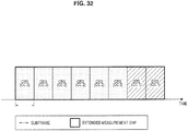
- FIG. 32 is an explanatory diagram for describing a first example of measurement according to the third embodiment.
- an extended measurement gap having a length of 8 subframes is shown.
- the measurement unit 163 performs measurement of a CC2 based on a CRS transmitted in the CC2 (a second frequency band) within a period (a second period) from a 1st subframe to a 6th subframe within the extended measurement gap.
- the measurement unit 163 performs measurement of a CC1 based on a DRS transmitted in the CC1 (a first frequency band) within a period (a first period) including a 7th sub frame and an 8th sub frame within the extended measurement gap.
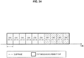
- FIG. 33 is an explanatory diagram for describing a second example of measurement according to the third embodiment.
- an extended measurement gap having a length of 8 subframes is shown.
- the measurement unit 163 performs measurement of a CC1 based on a DRS transmitted in the CC1 (a first frequency band) within a period (a first period) including a 1st subframe and a 2nd subframe within the extended measurement gap.
- the measurement unit 163 performs measurement of a CC2 based on a CRS transmitted in the CC2 (a second frequency band) within a period (a second period) from a 3rd sub frame to an 8th sub frame within the extended measurement gap.
- the terminal device 100-3 can perform measurement of the first frequency band based on a DRS while performing measurement of the second frequency band based on a CRS.
- the terminal device 100-3 can perform measurement of the second frequency band based on a CRS while performing measurement of the first frequency band based on a DRS. Therefore, measurement based on the DRS (that is, inter-frequency measurement of a frequency band that is used by a base station of a small cell) may be efficiently performed. As a specific example, measurement based on the DRS may be performed more quickly.
- the extended measurement gap may be shortened. That is, a period in which transmission of a signal from the terminal device 100-3 and transmission of a signal to the terminal device 100-3 are not continuous may be shortened.
- the measurement gap (that is, the extended measurement gap) may include an additional period.
- the measurement unit 163 may perform measurement of an additional frequency band based on a DRS transmitted in the additional frequency band within the additional period.
- this will be described with reference to a specific example of FIG. 34 .
- FIG. 34 is an explanatory diagram for describing a third example of measurement according to the third embodiment.
- the measurement unit 163 performs measurement of a CC2 based on a CRS transmitted in the CC2 (a second frequency band) within a period (a second period) from a 1st sub frame to a 6th sub frame within the extended measurement gap.
- the measurement unit 163 performs measurement of a CC1 based on a DRS transmitted in the CC1 (a first frequency band) within a period (a first period) including a 7th sub frame and an 8th sub frame within the extended measurement gap.
- the measurement unit 163 performs measurement of a CC3 based on a DRS transmitted in the CC3 (an additional frequency band) within a period (an additional period) including a 9th sub frame and a 10th sub frame within the extended measurement gap.
- measurement based on a DRS (that is, inter-frequency measurement) may be further efficiently performed.
- the measurement gap (that is, the extended measurement gap) includes one additional period and the measurement unit 163 performs measurement of one additional frequency band
- the third embodiment is not limited thereto.
- the measurement gap may include two or more additional periods, and the measurement unit 163 may perform measurement of two or more additional frequency bands.
- the measurement unit 163 may perform the measurement of the first frequency band that is used by the same base station based on a DRS and a CRS transmitted by the same base station in the first frequency band within the first period. Additionally or alternatively, the measurement unit 163 may perform the measurement of the second frequency band that is used by the same base station based on a DRS and a CRS transmitted by the same base station in the second frequency band within the second period.
- the first period may be a period shorter than 6 milliseconds.
- a base station of a small cell in the on state transmits both a DRS and a CRS in the second frequency band.
- the measurement unit 163 may perform measurement of the second frequency band that is used by the base station based on the DRS and the CRS transmitted by the base station in the second frequency band within the second period.
- this will be described with reference to a specific example of FIG. 35 .
- FIG. 35 is an explanatory diagram for describing a fourth example of measurement according to the third embodiment.
- the measurement unit 163 performs measurement of a CC2 based on a DRS and a CRS transmitted by the same base station using the CC2 (a second frequency band) within a period (a second period) from a 1st subframe to a 4th subframe within the extended measurement gap.
- the measurement unit 163 performs measurement of a CC1 based on a DRS transmitted in the CC1 (a first frequency band) within a period (a first period) including a 5th subframe and a 6th subframe within the measurement gap.
- the measurement unit 163 performs measurement of a CC3 based on a DRS transmitted in the CC3 (an additional frequency band) within a period (an additional period) including a 7th subframe and an 8th subframe within the extended measurement gap.
- the measurement of the first frequency band or the second frequency band is performed based on more reference signals. Therefore, the measurement of the first frequency band or the second frequency band used by the base station may be performed using a shorter period than when it is performed based on only a CRS. Therefore, the extended measurement gap may be shortened.
- the measurement unit 163 performs measurement of a frequency group and measurement of one or more other frequency bands or measurement of one or more other frequency groups based on a priority of the frequency group including the first frequency band and the second frequency band and a priority of the one or more other frequency bands or a priority of the one or more other frequency groups.
- a frequency group or a frequency band having a higher priority is sequentially selected from among the frequency group including the first frequency band and the second frequency band, the one or more other frequency bands and the one or more other frequency groups. Then, the measurement unit 163 performs measurement of the selected frequency group or frequency band.
- the priority of the frequency band is a priority included in an inter-frequency NCL contained in the SIB5.
- the priority of the frequency band may be a priority that is decided by the terminal device 100-3.
- the priority of the frequency group (and/or a priority of each of the one or more other frequency groups) may be decided in consideration of power consumption and/or a communication request of the terminal device 100-3.
- the priority of the frequency group may be higher. This is because, when the priority of the frequency group is high, measurement of more frequency bands using a measurement gap is performed.
- the priority of the frequency group may be lower. This is because, when the priority of the frequency group is low, measurement of a frequency band that is used by a base station of a cell in the on state is preferentially performed, and, as a result, a handover is preferentially performed without a transition time.
- the measurement unit 163 performs the measurement of the frequency group, the measurement of the one or more other frequency bands or the measurement of the one or more other frequency groups in consideration of a transmission period in which a DRS is transmitted in the first frequency band.
- the measurement unit 163 performs measurement of another frequency band or another frequency group whose priority is lower than the frequency group before the measurement of the frequency group outside of the transmission period.
- measurement may be performed more smoothly without wasting the measurement gap.
- the reporting unit 165 reports a result of measurement of the frequency band to the base station 200-3.
- the reporting unit 165 reports a result of measurement of the frequency band to the base station 200-3.
- the reporting unit 165 reports a result of measurement of the second frequency band to the base station 200-3.
- the frequency group may include an additional frequency band, and the reporting unit 165 may report a result of measurement of the additional frequency band to the base station 200-3.
- FIG. 36 is a block diagram illustrating an example of a configuration of the base station 200-3 according to the third embodiment.
- the base station 200-3 includes an antenna unit 210, a wireless communication unit 220, a network communication unit 230, a storage unit 240, and a processing unit 270.
- the processing unit 270 provides various functions of the base station 200-3.
- the processing unit 270 includes an information acquiring unit 271 and a control unit 273.
- the processing unit 270 may further include any other component in addition to the above-mentioned components. In other words, the processing unit 270 may also perform an operation other than operations of the above-mentioned components.
- the information acquiring unit 271 acquires information indicating a first frequency band in which a DRS is transmitted within at least a first period included in a measurement gap.
- the measurement gap is an extended measurement gap.
- the measurement gap further includes a second period in which a reference signal is transmitted in a second frequency band. More specifically, for example, the measurement gap includes a second period in which a CRS is transmitted in the second frequency band.
- the information acquiring unit 271 acquires information indicating a frequency group including the first frequency band and the second frequency band.
- the second frequency band is a frequency band in which a DRS is transmitted within at least a second period included in the measurement gap.
- a control entity 300-3 decides the frequency group and notifies the base station 200-3 of the frequency group. Then, the information indicating the frequency group is stored in the storage unit 240. The information acquiring unit 271 acquires the information indicating the frequency group at any time thereafter.
- the information acquiring unit 271 acquires information indicating the measurement gap.
- the measurement gap is an extended measurement gap.
- control entity 300-3 decides an extended measurement gap and notifies the base station 200-3 of the extended measurement gap. Then, the information indicating the extended measurement gap is stored in the storage unit 240. The information acquiring unit 271 acquires the information indicating the extended measurement gap at any time thereafter.
- the measurement gap is decided by a device other than the control entity 300-3, and the base station 200-3 may be notified thereof.
- the measurement gap is decided by the base station 200-3 and may be stored in the storage unit 240.
- the control unit 273 notifies the terminal device 100-3 of the first frequency band and the measurement gap.
- the measurement gap is an extended measurement gap.
- control unit 273 notifies the terminal device 100-3 of the frequency group including the first frequency band and the second frequency band and the measurement gap.
- control unit 273 transmits information indicating the frequency group and information indicating the measurement gap (that is, the extended measurement gap) to the terminal device 100-3 through the antenna unit 210 and the wireless communication unit 220.
- control unit 273 transmits an RRC connection reconfiguration message including a measurement configuration including the information indicating the frequency group and the information indicating the measurement gap to the terminal device 100-3 through the antenna unit 210 and the wireless communication unit 220.
- control unit 273 notifies the terminal device 100-3 of a priority of the frequency group and a priority of one or more other frequency bands or a priority of one or more other frequency groups.
- control unit 273 transmits information indicating the priority of the frequency group and the priority of one or more other frequency bands or the priority of one or more other frequency groups to the terminal device 100-3 through the antenna unit 210 and the wireless communication unit 220.
- the information is included in the inter-frequency NCL within the SIB5 and the control unit 273 informs the terminal device 100-3 of the SIB5 including the inter-frequency NCL through the antenna unit 210 and the wireless communication unit 220.
- FIG. 37 is a block diagram illustrating an example of a configuration of the control entity 300-3 according to the third embodiment.
- the control entity 300-3 includes a communication unit 310, a storage unit 320, and a processing unit 340.
- the processing unit 340 provides various functions of the control entity 300-3.
- the processing unit 340 includes an information acquiring unit 341 and a control unit 343.
- the processing unit 340 may further include any other component in addition to the above-mentioned components. In other words, the processing unit 340 may also perform an operation other than operations of the above-mentioned components.
- the information acquiring unit 341 acquires information about a first frequency band in which a DRS is transmitted.
- the first frequency band is a frequency band that is used by a base station of a small cell.
- the first frequency band is a frequency band that is used by the base station of the small cell in the off state.
- the first frequency band is a frequency band that is used by the base station of the small cell.
- control unit 343 controls the transmission period such that at least a part of the transmission period is included in the extended measurement gap.
- control unit 343 decides an extended measurement gap. Then, the control unit 343 instructs a base station that transmits a DRS in the first frequency band to transmit a DRS during the extended measurement gap.
- the information about the first frequency band may include information indicating the transmission period.
- the control unit 343 may decide the extended measurement gap based on the transmission period (that is, a period in which a DRS is transmitted in the first frequency band).
- the transmission period and the extended measurement gap are periods having the same length, and the control unit 343 decides the extended measurement gap such that the extended measurement gap matches the transmission period.
- the transmission period may be a period longer than the extended measurement gap, and the control unit 343 may decide the extended measurement gap such that the extended measurement gap is included in the transmission period.
- the transmission period may be a period shorter than the extended measurement gap, and the control unit 343 may decide the extended measurement gap such that the extended measurement gap includes the entire transmission period.
- control unit 343 decides a frequency group including at least the first frequency band and the second frequency band.
- the first frequency band is a frequency band in which a DRS is transmitted within at least a first period included in the measurement gap.
- the second frequency band is a frequency band in which a reference signal is transmitted within at least a second period included in the measurement gap.
- the reference signal is a CRS.
- control unit 343 selects any frequency band in which a CRS is transmitted (for example, a frequency band used by a base station of a macro cell or a frequency band used by a base station of a small in the on state) as the second frequency band. Then, the control unit 343 decides a frequency group including the first frequency band and the second frequency band.
- the reference signal transmitted in the second frequency band may be a DRS.
- the control unit 343 may decide the frequency group in the same manner as in the control unit 333 according to the second embodiment.
- control unit 343 notifies the base station 200-3 of the first frequency band.
- control unit 343 notifies the base station 200-3 of the frequency group including the first frequency band and the second frequency band.
- control unit 343 transmits a message including information indicating the frequency group and information indicating the extended measurement gap to the base station 200-3 through the communication unit 310.
- FIG. 38 is a sequence diagram illustrating an example of a schematic flow of a process according to the third embodiment.
- the control entity 300-3 performs an extended measurement gap decision process (S470). That is, the control unit 343 decides an extended measurement gap including at least a part of a transmission period in which a DRS is transmitted in a first frequency band.
- S470 an extended measurement gap decision process
- control entity 300-3 decides a frequency group including at least the first frequency band and a second frequency band (5491).
- control entity 300-3 notifies the base station 200-3 of the frequency group and the extended measurement gap (S493).
- the base station 200-3 notifies the terminal device 100-3 of the frequency group and the extended measurement gap (S495).
- the terminal device 100-3 performs measurement of the frequency group (S497).
- the measurement unit 163 performs measurement of the first frequency band based on a DRS transmitted in the first frequency band within a first period included in the extended measurement gap.
- the measurement unit 163 performs measurement of the second frequency band based on a reference signal (for example, a CRS) transmitted in the second frequency band within a second period included in the extended measurement gap.
- a reference signal for example, a CRS
- the information acquiring unit 341 acquires information about a first frequency band in which a DRS is transmitted (5471).
- control unit 343 decides an extended measurement gap (S473).
- control unit 343 controls a transmission period in which a DRS is transmitted in the first frequency band such that the DRS is transmitted in the first frequency band within at least a first period included in the extended measurement gap (S475). For example, the control unit 343 instructs a base station that transmits a DRS in the first frequency band to transmit the DRS during the extended measurement gap. Then, the process ends.
- FIG. 40 is a sequence diagram illustrating a second example of a schematic flow of an extended measurement gap decision process according to the third embodiment.
- the information acquiring unit 341 acquires information about a first frequency band in which a DRS is transmitted (S481).
- the information includes information indicating a transmission period in which a DRS is transmitted in the first frequency band.
- control unit 343 decides an extended measurement gap based on the transmission period (that is, a period in which a DRS is transmitted in the first frequency band) (S483). Then, the process ends.
- the base station 200-3 decides the extended measurement gap instead of the control entity 300-3. In addition, for example, the base station 200-3 decides the frequency group. Then, the base station 200-3 notifies the terminal device 100-3 of the extended measurement gap and the frequency group it decided.
- the processing unit 270 of the base station 200-3 further includes, for example, the information acquiring unit 341 and the control unit 343.
- the terminal device 100-3 decides the extended measurement gap instead of the control entity 300-3.
- the terminal device 100-3 decides the frequency group.
- the base station 200-3 performs measurement of the frequency group it decided by using the extended measurement gap it decided.
- the processing unit 160 decides the extended measurement gap.
- the processing unit 160 decides a frequency group including at least a first frequency band in which a DRS is transmitted and a second frequency band in which a reference signal (for example, a CRS) is transmitted.
- the base station 200-3 notifies the terminal device 100-3 of information about a first frequency band in which a DRS is transmitted.
- the base station 200-3 informs of the inter-frequency NCL (SIB5) including information indicating whether a DRS is transmitted for each frequency band and a transmission period of a DRS.
- the processing unit 160 decides an extended measurement gap including at least a part of the transmission period in which a DRS is transmitted in the first frequency band.
- the processing unit 160 decides a frequency group including at least the first frequency band and the second frequency band.
- the processing unit 160 decides frequency bands whose number is equal to or less than a predetermined maximum number as a frequency group.
- Terminal device 100-3 information acquiring unit 161
- the information acquiring unit 161 acquires information indicating the first frequency band (or the frequency group). In addition, as described above, the information acquiring unit 161 acquires information indicating the extended measurement gap.
- a terminal device 100-4 performs first measurement of each of a plurality of frequency bands and second measurement of each of one or more frequency bands that are a part of the plurality of frequency bands.
- the first measurement is measurement that is performed based on a reference signal transmitted within a period having a first length.
- the second measurement is measurement that is performed based on a reference signal transmitted within a period having a second length that is greater than the first length. That is, in the fourth embodiment, the terminal device 100-4 performs rough measurement of more frequency bands and performs more accurate measurement of fewer frequency bands that are a part of the more frequency bands. Accordingly, for example, it is possible to improve measurement performed by the terminal device 100-4.
- FIG. 41 is a block diagram illustrating an example of a configuration of the terminal device 100-4 according to the fourth embodiment.
- the terminal device 100-4 includes the antenna unit 110, the wireless communication unit 120, the storage unit 130 and a processing unit 170.
- the processing unit 170 provides various functions of the terminal device 100-4.
- the processing unit 170 includes an information acquiring unit 171, a measurement unit 173 and a reporting unit 175.
- the processing unit 170 may further include a component other than these components. That is, the processing unit 170 may also perform an operation other than operations of these components.
- the information acquiring unit 171 acquires information about a frequency band.
- the information acquiring unit 171 acquires a neighbor cell list.
- the information acquiring unit 171 acquires an intra-frequency NCL and an inter-frequency NCL.
- a base station 200-4 informs the information acquiring unit 171 of an intra-frequency NCL within an SIB4, and the information acquiring unit 171 acquires the intra-frequency NCL.
- the base station 200-4 informs the information acquiring unit 171 of an inter-frequency NCL within an SIB5 and the information acquiring unit 171 acquires the inter-frequency NCL.
- the information acquiring unit 171 acquires a measurement configuration of a frequency band.
- the base station 200-4 transmits an RRC connection reconfiguration message including a measurement configuration to the terminal device 100-4, and the information acquiring unit 171 acquires the measurement configuration.
- the measurement configuration includes information such as measurement objects, reporting configurations, measurement IDs and measurement gaps.
- the measurement unit 173 performs measurement of a frequency band.
- the measurement unit 173 performs first measurement of each of a plurality of frequency bands and second measurement of each of one or more frequency bands that are a part of the plurality of frequency bands.
- the first measurement is measurement that is performed based on a reference signal transmitted within a period having a first length.
- the second measurement is measurement that is performed based on a reference signal transmitted within a period having a second length that is greater than the first length. That is, the measurement unit 173 performs rough measurement of more frequency bands (that is, the plurality of frequency bands) and performs more accurate measurement of fewer frequency bands (that is, the one or more frequency bands) that are a part of the more frequency bands. Accordingly, for example, it is possible to improve measurement performed by the terminal device 100-4. For example, measurement of the frequency band may be performed more efficiently.
- each of the plurality of frequency bands is a component carrier (CC) of carrier aggregation.
- CC component carrier
- each of the plurality of frequency bands is a frequency band that is used by a base station of a small cell. Accordingly, for example, measurement of the frequency band used in the small cell may be performed more efficiently.
- each of the plurality of frequency bands is a frequency band that is not used by the terminal device 100-4. Accordingly, for example, inter-frequency measurement may be performed more efficiently.
- each of the plurality of frequency bands is a CC that is used by a base station of a small cell, and the CC is not used by the terminal device 100-4.
- the plurality of frequency bands have been described above.
- the fourth embodiment is not limited thereto.
- the plurality of frequency bands may include a frequency band that is used by only a macro base station.
- the first measurement (that is, the measurement of each of the plurality of frequency bands) is measurement that is performed based on a reference signal transmitted within a period having the first length.
- the period having the first length is a period including a measurement gap of a first number. That is, the measurement unit 173 performs measurement of each of the plurality of frequency bands based on a reference signal transmitted within the period including the measurement gap of the first number.
- the reference signal is a CRS. Accordingly, for example, measurement regarding a small cell in the on state may be performed more efficiently. In addition, a measurement load regarding a macro cell may be reduced.
- the reference signal may be a DRS. Accordingly, for example, measurement regarding a small cell in the off state may be performed more efficiently.
- the first measurement is RRM measurement, for example, measurement of reception power or reception quality.
- the first measurement is measurement of RSRP or RSRQ.
- the first measurement is performed for each cell (that is, a base station that uses each of the plurality of frequency bands) in which each of the plurality of frequency bands is used.
- the one or more frequency bands are frequency bands the first measurement of which has a more favorable result.
- the one or more frequency bands are frequency bands having higher RSRP (or RSRQ).
- RSRP or RSRQ
- FIG. 42 is an explanatory diagram for describing an example of frequency bands that are targets of first measurement and second measurement according to the fourth embodiment.
- five CCs in one operating band are shown.
- the measurement unit 173 performs first measurement of each of the five CCs.
- two CCs having higher RSRP (or RSRQ) among the five CCs are selected as targets of the second measurement, and the measurement unit 173 performs the second measurement of the two CCs.
- the first measurement is measurement that is performed based on a reference signal transmitted within a period having the first length.
- the second measurement is measurement that is performed based on a reference signal transmitted within a period having a second length that is greater than the first length.
- the period having the first length is a period including a measurement gap of a first number.
- the period having the second length is a period including a measurement gap of a second number that is greater than the first number. That is, the measurement unit 173 performs measurement of each of the one or more frequency bands based on a reference signal transmitted within a period including the measurement gap of the second number that is greater than the first number.
- the reference signal is a CRS.
- the reference signal may be a DRS.
- the second measurement is RRM measurement, for example, measurement of reception power or reception quality.
- the second measurement is measurement of RSRP or RSRQ.
- the second measurement is performed for each cell in which each of the one or more frequency bands is used (that is, a base station that uses each of the one or more frequency bands).
- the reporting unit 175 reports a result of measurement of the frequency band to the base station 200-4.
- the reporting unit 175 reports a result of measurement of each of the one or more frequency bands to the base station 200-4.
- FIG. 42 is a flowchart illustrating an example of a schematic flow of a process according to the fourth embodiment.
- the measurement unit 173 performs first measurement of each of a plurality of frequency bands (5511).
- the processing unit 170 selects one or more frequency bands that are a part of the plurality of frequency bands based on a result of the first measurement of each of the plurality of frequency bands (S513).
- the measurement unit 173 performs second measurement of each of the one or more frequency bands (S515). Then, the process ends.
- the technology according to the present disclosure is applicable to a variety of products.
- the control entity 300 may be implemented as any type of server such as tower servers, rack servers, and blade servers. At least a part of components of the control entity 300 may be implemented in a module (e.g. integrated circuit module that includes a single die, or card or blade that is inserted into a slot of a blade server) mounted on a server. In addition, the control entity 300 may be implemented as any of various base stations which will be described.
- the base station 200 may also be implemented, for example, as any type of evolved Node B (eNB) such as macro eNBs and small eNBs. Small eNBs may cover smaller cells than the macrocells of pico eNBs, micro eNBs, or home (femt) eNBs. Instead, the base station 200 may be implemented as another type of base station such as Nodes B or base transceiver stations (BTSs).
- the base station 200 may include the main apparatus (which is also referred to as base station apparatus) that controls wireless communication and one or more remote radio heads (RRHs) that are disposed at different locations from that of the main apparatus.
- RRHs remote radio heads
- various types of terminals as will be discussed later may temporarily or semi-persistently execute the base station function to operate as the base station 200. Further, at least part of components of the base station 200 may be implemented in a base station device or a module for the base station device.
- the terminal device 100 may be implemented as a mobile terminal such as smartphones, tablet personal computers (PCs), notebook PCs, portable game terminals, portable/dongle mobile routers, and digital cameras, or an in-vehicle terminal such as car navigation apparatuses.
- the terminal device 100 may also be implemented as a terminal (which is also referred to as machine type communication (MTC) terminal) that performs machine to machine (M2M) communication.
- MTC machine type communication
- M2M machine to machine
- at least part of components of the terminal device 100 may be implemented as a module (e.g. integrated circuit module constituted with a single die) that is mounted on these terminals.
- FIG. 44 is a block diagram illustrating an example of a schematic configuration of a server 700 to which the technology according to the present disclosure may be applied.
- the server 700 includes a processor 701, a memory 702, a storage 703, a network interface 704, and a bus 706.
- the processor 701 may be, for example, a central processing unit (CPU) or a digital signal processor (DSP), and controls various functions of the server 700.
- the memory 702 includes a random access memory (RAM) and a read only memory (ROM), and stores a program executed by the processor 701 and data.
- the storage 703 can include a storage medium such as semiconductor memories and hard disks.
- the network interface 704 is a wired communication interface for connecting the server 700 to a wired communication network 705.
- the wired communication network 705 may be a core network such as evolved packet cores (EPCs), or a packet data network (PDN) such as the Internet.
- EPCs evolved packet cores
- PDN packet data network
- the bus 706 connects the processor 701, the memory 702, the storage 703, and the network interface 704 to each other.
- the bus 706 may include two or more buses each having different speed (e.g. high speed bus and low speed bus).
- one or more components included in the processing unit 330 described above with reference to FIG. 27 may be mounted in the processor 701.
- a program causing the processor to function as one or more of the components above may be installed in the server 700, and the processor 701 may execute the program.
- the server 700 may include a module including the processor 701 and the memory 702, and one or more of the components above may be mounted in the module.
- the module may store the program causing the processor to function as one or more of the components above in the memory 702, and the program may be executed by the processor 701.
- the server 700 or the module may be provided as an apparatus including one or more of the components above, and the program causing the processor to function as one or more of the components above may be provided.
- a readable recording medium in which the program is recorded may be provided.
- FIG. 45 is a block diagram illustrating a first example of a schematic configuration of an eNB to which the technology according to the present disclosure may be applied.
- An eNB 800 includes one or more antennas 810 and a base station apparatus 820. Each antenna 810 and the base station apparatus 820 may be connected to each other via an RF cable.
- Each of the antennas 810 includes a single or a plurality of antenna elements (e.g. a plurality of antenna elements constituting a MIMO antenna) and is used for the base station apparatus 820 to transmit and receive a wireless signal.
- the eNB 800 may include the plurality of the antennas 810 as illustrated in FIG. 45 , and the plurality of antennas 810 may, for example, correspond to a plurality of frequency bands used by the eNB 800. It should be noted that while FIG. 45 illustrates an example in which the eNB 800 includes the plurality of antennas 810, the eNB 800 may include the single antenna 810.
- the base station apparatus 820 includes a controller 821, a memory 822, a network interface 823, and a wireless communication interface 825.
- the controller 821 may be, for example, a CPU or a DSP, and operates various functions of an upper layer of the base station apparatus 820. For example, the controller 821 generates a data packet from data in a signal processed by the wireless communication interface 825, and transfers the generated packet via the network interface 823. The controller 821 may generate a bundled packet by bundling data from a plurality of base band processors to transfer the generated bundled packet. The controller 821 may also have a logical function of performing control such as radio resource control, radio bearer control, mobility management, admission control, and scheduling. The control may be performed in cooperation with a surrounding eNB or a core network.
- the memory 822 includes a RAM and a ROM, and stores a program executed by the controller 821 and a variety of control data (such as, for example, terminal list, transmission power data, and scheduling data).
- the network interface 823 is a communication interface for connecting the base station apparatus 820 to the core network 824.
- the controller 821 may communicate with a core network node or another eNB via the network interface 823.
- the controller 821 may be mutually connected to the eNB 800 and a core network node or another eNB through a logical interface (e.g. S1 interface or X2 interface).
- the network interface 823 may be a wired communication interface or a wireless communication interface for wireless backhaul.
- the network interface 823 may use a higher frequency band for wireless communication than a frequency band used by the wireless communication interface 825.
- the wireless communication interface 825 supports a cellular communication system such as long term evolution (LTE) or LTE-Advanced, and provides wireless connection to a terminal located within the cell of the eNB 800 via the antenna 810.
- the wireless communication interface 825 may typically include a base band (BB) processor 826 and an RF circuit 827.
- the BB processor 826 may, for example, perform encoding/decoding, modulation/demodulation, multiplexing/demultiplexing, and the like, and performs a variety of signal processing on each layer (e.g. L1, medium access control (MAC), radio link control (RLC), and packet data convergence protocol (PDCP)).
- the BB processor 826 may have part or all of the logical functions as discussed above instead of the controller 821.
- the BB processor 826 may be a module including a memory having a communication control program stored therein, a processor to execute the program, and a related circuit, and the function of the BB processor 826 may be changeable by updating the program.
- the module may be a card or blade to be inserted into a slot of the base station apparatus 820, or a chip mounted on the card or the blade.
- the RF circuit 827 may include a mixer, a filter, an amplifier, and the like, and transmits and receives a wireless signal via the antenna 810.
- the wireless communication interface 825 may include a plurality of the BB processors 826 as illustrated in FIG. 45 , and the plurality of BB processors 826 may, for example, correspond to a plurality of frequency bands used by the eNB 800.
- the wireless communication interface 825 may also include a plurality of the RF circuits 827, as illustrated in FIG. 45 , and the plurality of RF circuits 827 may, for example, correspond to a plurality of antenna elements.
- FIG. 45 illustrates an example in which the wireless communication interface 825 includes the plurality of BB processors 826 and the plurality of RF circuits 827, but the wireless communication interface 825 may include the single BB processor 826 or the single RF circuit 827.
- one or more components included in the processing unit 250 described above with reference to FIG. 16 may be mounted in the wireless communication interface 825.
- the eNB 800 may be equipped with a module including some or all components of the wireless communication interface 825 (for example, the BB processor 826) and/or the controller 821, and one or more of the components above may be mounted in the module.
- the module may store a program causing the processor to function as one or more of the components above (that is, a program causing the processor to perform the operation of one or more of the components above) and execute the program.
- the program causing the processor to function as one or more of the components above may be installed in the eNB 800, and the wireless communication interface 825 (for example, the BB processor 826) and/or the controller 821 may execute the program.
- the eNB 800, the base station apparatus 820, or the module may be provided as an apparatus including one or more of the components above, and the program causing the processor to function as one or more of the components above may be provided.
- a readable recording medium in which the program is recorded may be provided.
- the wireless communication unit 220 described above with reference to FIG. 16 may be mounted in the wireless communication interface 825 (for example, the RF circuit 827).
- the antenna unit 210 may be mounted in the antenna 810.
- the network communication unit 230 may be mounted in the controller 821 and/or the network interface 823.
- FIG. 46 is a block diagram illustrating a second example of a schematic configuration of an eNB to which the technology according to the present disclosure may be applied.
- An eNB 830 includes one or more antennas 840, a base station apparatus 850, and an RRH 860. Each of the antennas 840 and the RRH 860 may be connected to each other via an RF cable. The base station apparatus 850 and the RRH 860 may be connected to each other by a high speed line such as optical fiber cables.
- Each of the antennas 840 includes a single or a plurality of antenna elements (e.g. antenna elements constituting a MIMO antenna), and is used for the RRH 860 to transmit and receive a wireless signal.
- the eNB 830 may include a plurality of the antennas 840 as illustrated in FIG. 46 , and the plurality of antennas 840 may, for example, correspond to a plurality of frequency bands used by the eNB 830.
- FIG. 46 illustrates an example in which the eNB 830 includes the plurality of antennas 840, but the eNB 830 may include the single antenna 840.
- the base station apparatus 850 includes a controller 851, a memory 852, a network interface 853, a wireless communication interface 855, and a connection interface 857.
- the controller 851, the memory 852, and the network interface 853 are the same as the controller 821, the memory 822, and the network interface 823 described with reference to FIG. 45 .
- the wireless communication interface 855 supports a cellular communication system such as LTE and LTE-Advanced, and provides wireless connection to a terminal located in a sector corresponding to the RRH 860 via the RRH 860 and the antenna 840.
- the wireless communication interface 855 may typically include a BB processor 856.
- the BB processor 856 is the same as the BB processor 826 described with reference to FIG. 45 except that the BB processor 856 is connected to an RF circuit 864 of the RRH 860 via the connection interface 857.
- the wireless communication interface 855 may include a plurality of the BB processors 856, as illustrated in FIG.
- FIG. 46 illustrates an example in which the wireless communication interface 855 includes the plurality of BB processors 856, but the wireless communication interface 855 may include the single BB processor 856.
- connection interface 857 is an interface for connecting the base station apparatus 850 (wireless communication interface 855) to the RRH 860.
- the connection interface 857 may be a communication module for communication on the high speed line which connects the base station apparatus 850 (wireless communication interface 855) to the RRH 860.
- the RRH 860 includes a connection interface 861 and a wireless communication interface 863.
- connection interface 861 is an interface for connecting the RRH 860 (wireless communication interface 863) to the base station apparatus 850.
- the connection interface 861 may be a communication module for communication on the high speed line.
- the wireless communication interface 863 transmits and receives a wireless signal via the antenna 840.
- the wireless communication interface 863 may typically include the RF circuit 864.
- the RF circuit 864 may include a mixer, a filter, an amplifier and the like, and transmits and receives a wireless signal via the antenna 840.
- the wireless communication interface 863 may include a plurality of the RF circuits 864 as illustrated in FIG. 46 , and the plurality of RF circuits 864 may, for example, correspond to a plurality of antenna elements.
- FIG. 46 illustrates an example in which the wireless communication interface 863 includes the plurality of RF circuits 864, but the wireless communication interface 863 may include the single RF circuit 864.
- one or more components included in the processing unit 250 described above with reference to FIG. 16 may be mounted in the wireless communication interface 855 and/or the wireless communication interface 863.
- the eNB 830 may be equipped with a module including some or all components of the wireless communication interface 855 (for example, the BB processor 856) and/or the controller 851, and one or more of the components above may be mounted in the module.
- the module may store a program causing the processor to function as one or more of the components above (that is, a program causing the processor to perform the operation of one or more of the components above) and execute the program.
- the program causing the processor to function as one or more of the components above may be installed in the eNB 830, and the wireless communication interface 855 (for example, the BB processor 856) and/or the controller 851 may execute the program.
- the eNB 830, the base station apparatus 850, or the module may be provided as an apparatus including one or more of the components above, and the program causing the processor to function as one or more of the components above may be provided.
- a readable recording medium in which the program is recorded may be provided.
- one or more components included in the processing unit 260 described above with reference to FIG. 26 (the information acquiring unit 261 and/or the control unit 263), and one or more components included in the processing unit 270 described above with reference to FIG. 36 (the information acquiring unit 271 and/or the control unit 273) are the same as one or more of the components above included in the processing unit 250.
- the wireless communication unit 220 described above with reference to FIG. 16 may be mounted in the wireless communication interface 863 (for example, the RF circuit 864).
- the antenna unit 210 may be mounted in the antenna 840.
- the network communication unit 230 may be mounted in the controller 851 and/or the network interface 853.
- FIG. 47 is a block diagram illustrating an example of a schematic configuration of a smartphone 900 to which the technology according to the present disclosure may be applied.
- the smartphone 900 includes a processor 901, a memory 902, a storage 903, an external connection interface 904, a camera 906, a sensor 907, a microphone 908, an input device 909, a display device 910, a speaker 911, a wireless communication interface 912, one or more antenna switches 915, one or more antennas 916, a bus 917, a battery 918, and a secondary controller 919.
- the processor 901 may be, for example, a CPU or a system on chip (SoC), and controls the functions of an application layer and other layers of the smartphone 900.
- the memory 902 includes a RAM and a ROM, and stores a program executed by the processor 901 and data.
- the storage 903 may include a storage medium such as semiconductor memories and hard disks.
- the external connection interface 904 is an interface for connecting the smartphone 900 to an externally attached device such as memory cards and universal serial bus (USB) devices.
- the camera 906 includes an image sensor such as charge coupled devices (CCDs) and complementary metal oxide semiconductor (CMOS), and generates a captured image.
- the sensor 907 may include a sensor group including, for example, a positioning sensor, a gyro sensor, a geomagnetic sensor, and an acceleration sensor.
- the microphone 908 converts a sound that is input into the smartphone 900 to an audio signal.
- the input device 909 includes, for example, a touch sensor which detects that a screen of the display device 910 is touched, a key pad, a keyboard, a button, or a switch, and accepts an operation or an information input from a user.
- the display device 910 includes a screen such as liquid crystal displays (LCDs) and organic light emitting diode (OLED) displays, and displays an output image of the smartphone 900.
- the speaker 911 converts the audio signal that is output from the smartphone 900 to a sound.
- the wireless communication interface 912 supports a cellular communication system such as LTE or LTE-Advanced, and performs wireless communication.
- the wireless communication interface 912 may typically include the BB processor 913, the RF circuit 914, and the like.
- the BB processor 913 may, for example, perform encoding/decoding, modulation/demodulation, multiplexing/demultiplexing, and the like, and performs a variety of types of signal processing for wireless communication.
- the RF circuit 914 may include a mixer, a filter, an amplifier, and the like, and transmits and receives a wireless signal via the antenna 916.
- the wireless communication interface 912 may be a one-chip module in which the BB processor 913 and the RF circuit 914 are integrated.
- the wireless communication interface 912 may include a plurality of BB processors 913 and a plurality of RF circuits 914 as illustrated in FIG. 47.
- FIG. 47 illustrates an example in which the wireless communication interface 912 includes a plurality of BB processors 913 and a plurality of RF circuits 914, but the wireless communication interface 912 may include a single BB processor 913 or a single RF circuit 914.
- the wireless communication interface 912 may support other types of wireless communication system such as a short range wireless communication system, a near field communication system, and a wireless local area network (LAN) system in addition to the cellular communication system, and in this case, the wireless communication interface 912 may include the BB processor 913 and the RF circuit 914 for each wireless communication system.
- Each antenna switch 915 switches a connection destination of the antenna 916 among a plurality of circuits (for example, circuits for different wireless communication systems) included in the wireless communication interface 912.
- Each of the antennas 916 includes one or more antenna elements (for example, a plurality of antenna elements constituting a MIMO antenna) and is used for transmission and reception of the wireless signal by the wireless communication interface 912.
- the smartphone 900 may include a plurality of antennas 916 as illustrated in FIG. 47.
- FIG. 47 illustrates an example in which the smartphone 900 includes a plurality of antennas 916, but the smartphone 900 may include a single antenna 916.
- the smartphone 900 may include the antenna 916 for each wireless communication system.
- the antenna switch 915 may be omitted from a configuration of the smartphone 900.
- the bus 917 connects the processor 901, the memory 902, the storage 903, the external connection interface 904, the camera 906, the sensor 907, the microphone 908, the input device 909, the display device 910, the speaker 911, the wireless communication interface 912, and the secondary controller 919 to each other.
- the battery 918 supplies electric power to each block of the smartphone 900 illustrated in FIG. 47 via a feeder line that is partially illustrated in the figure as a dashed line.
- the secondary controller 919 for example, operates a minimally necessary function of the smartphone 900 in a sleep mode.
- one or more components included in the processing unit 140 described above with reference to FIG. 12 may be mounted in the wireless communication interface 912.
- the smartphone 900 may be equipped with a module including some or all components of the wireless communication interface 912 (for example, the BB processor 913), the processor 901, and/or the secondary controller 919, and one or more of the components above may be mounted in the module.
- the module may store a program causing the processor to function as one or more of the components above (that is, a program causing the processor to perform the operation of one or more of the components above) and execute the program.
- the program causing the processor to function as one or more of the components above may be installed in the smartphone 900, and the wireless communication interface 912 (for example, the BB processor 913), the processor 901, and/or the secondary controller 919 may execute the program.
- the smartphone 900 or the module may be provided as an apparatus including one or more of the components above, and the program causing the processor to function as one or more of the components above may be provided.
- a readable recording medium in which the program is recorded may be provided.
- one or more components included in the processing unit 150 described above with reference to FIG. 22 (the information acquiring unit 151, the measurement unit 153, and/or the reporting unit 155), one or more components included in the processing unit 160 described above with reference to FIG. 31 (the information acquiring unit 161, the measurement unit 163, and/or the reporting unit 165), and one or more components included in the processing unit 170 described above with reference to FIG. 41 (the information acquiring unit 171, the measurement unit 173, and/or the reporting unit 175) are the same as one or more of the components above included in the processing unit 140.
- the wireless communication unit 120 described above with reference to FIG. 12 may be mounted in the wireless communication interface 912 (for example, the RF circuit 914).
- the antenna unit 110 may be mounted in the antenna 916.
- FIG. 48 is a block diagram illustrating an example of a schematic configuration of a car navigation apparatus 920 to which the technology according to the present disclosure may be applied.
- the car navigation apparatus 920 includes a processor 921, a memory 922, a global positioning system (GPS) module 924, a sensor 925, a data interface 926, a content player 927, a storage medium interface 928, an input device 929, a display device 930, a speaker 931, a wireless communication interface 933, one or more antenna switches 936, one or more antennas 937, and a battery 938.
- GPS global positioning system
- the processor 921 may be, for example, a CPU or an SoC, and controls the navigation function and the other functions of the car navigation apparatus 920.
- the memory 922 includes a RAM and a ROM, and stores a program executed by the processor 921 and data.
- the GPS module 924 uses a GPS signal received from a GPS satellite to measure the position (e.g. latitude, longitude, and altitude) of the car navigation apparatus 920.
- the sensor 925 may include a sensor group including, for example, a gyro sensor, a geomagnetic sensor, and an air pressure sensor.
- the data interface 926 is, for example, connected to an in-vehicle network 941 via a terminal that is not illustrated, and acquires data such as vehicle speed data generated on the vehicle side.
- the content player 927 reproduces content stored in a storage medium (e.g. CD or DVD) inserted into the storage medium interface 928.
- the input device 929 includes, for example, a touch sensor which detects that a screen of the display device 930 is touched, a button, or a switch, and accepts operation or information input from a user.
- the display device 930 includes a screen such as LCDs and OLED displays, and displays an image of the navigation function or the reproduced content.
- the speaker 931 outputs a sound of the navigation function or the reproduced content.
- the wireless communication interface 933 supports a cellular communication system such as LTE or LTE-Advanced, and performs wireless communication.
- the wireless communication interface 933 may typically include the BB processor 934, the RF circuit 935, and the like.
- the BB processor 934 may, for example, perform encoding/decoding, modulation/demodulation, multiplexing/demultiplexing, and the like, and performs a variety of types of signal processing for wireless communication.
- the RF circuit 935 may include a mixer, a filter, an amplifier, and the like, and transmits and receives a wireless signal via the antenna 937.
- the wireless communication interface 933 may be a one-chip module in which the BB processor 934 and the RF circuit 935 are integrated.
- the wireless communication interface 933 may include a plurality of BB processors 934 and a plurality of RF circuits 935 as illustrated in FIG. 48.
- FIG. 48 illustrates an example in which the wireless communication interface 933 includes a plurality of BB processors 934 and a plurality of RF circuits 935, but the wireless communication interface 933 may be a single BB processor 934 or a single RF circuit 935.
- the wireless communication interface 933 may support other types of wireless communication system such as a short range wireless communication system, a near field communication system, and a wireless LAN system in addition to the cellular communication system, and in this case, the wireless communication interface 933 may include the BB processor 934 and the RF circuit 935 for each wireless communication system.
- Each antenna switch 936 switches a connection destination of the antenna 937 among a plurality of circuits (for example, circuits for different wireless communication systems) included in the wireless communication interface 933.
- Each of the antennas 937 includes one or more antenna elements (for example, a plurality of antenna elements constituting a MIMO antenna) and is used for transmission and reception of the wireless signal by the wireless communication interface 933.
- the car navigation apparatus 920 includes a plurality of antennas 937 as illustrated in FIG. 48.
- FIG. 48 illustrates an example in which the car navigation apparatus 920 includes a plurality of antennas 937, but the car navigation apparatus 920 may include a single antenna 937.
- the smartphone 920 may include the antenna 937 for each wireless communication system.
- the antenna switch 936 may be omitted from a configuration of the car navigation apparatus 920.
- the battery 950 supplies electric power to each block of the car navigation apparatus 930 illustrated in FIG. 48 via a feeder line that is partially illustrated in the figure as a dashed line.
- the battery 950 accumulates the electric power supplied from the vehicle.
- one or more components included in the processing unit 140 described above with reference to FIG. 12 may be mounted in the wireless communication interface 933.
- the processing unit 140 described above with reference to FIG. 12 may be mounted in the wireless communication interface 933.
- the processor 921 may be mounted in the processor 921.
- the car navigation apparatus 920 may be equipped with a module including some or all components of the wireless communication interface 933 (for example, the BB processor 934), and/or the processor 921, and one or more of the components above may be mounted in the module.
- the module may store a program causing the processor to function as one or more of the components above (that is, a program causing the processor to perform the operation of one or more of the components above) and execute the program.
- the program causing the processor to function as one or more of the components above may be installed in the car navigation apparatus 920, and the wireless communication interface 933 (for example, the BB processor 934), and/or the processor 921 may execute the program.
- the car navigation apparatus 920 or the module may be provided as an apparatus including one or more of the components above, and the program causing the processor to function as one or more of the components above may be provided.
- a readable recording medium in which the program is recorded may be provided.
- one or more components included in the processing unit 150 described above with reference to FIG. 22 (the information acquiring unit 151, the measurement unit 153, and/or the reporting unit 155), one or more components included in the processing unit 160 described above with reference to FIG. 31 (the information acquiring unit 161, the measurement unit 163, and/or the reporting unit 165), and one or more components included in the processing unit 170 described above with reference to FIG. 41 (the information acquiring unit 171, the measurement unit 173, and/or the reporting unit 175) are the same as one or more of the components above included in the processing unit 140.
- the wireless communication unit 120 described above with reference to FIG. 12 may be mounted in the wireless communication interface 933 (for example, the RF circuit 935).
- the antenna unit 110 may be mounted in the antenna 937.
- the technique according to the present disclosure may be implemented as an in-vehicle system (or a vehicle) 940 including one or more blocks of the above-described car navigation apparatus 920, an in-vehicle network 941 and a vehicle side module 942. That is, the in-vehicle system (or the vehicle) 940 may be provided as an apparatus including one more of the components above included in the processing unit 140 (or the processing unit 150, the processing unit 160 or the processing unit 170).
- the vehicle side module 942 generates vehicle side data such as vehicle speed, engine speed and failure information and outputs the generated data to the in-vehicle network 961.
- measurement of each of one or more frequency bands that are a part of a plurality of frequency bands that are not used by the terminal device 100-1 is performed.
- the terminal device 100-1 does not perform measurement of each of the remaining frequency bands among the plurality of frequency bands or performs the measurement of each of the remaining frequency bands at a frequency lower than a frequency of the measurements of each of the one or more frequency bands.
- the terminal device 100-2 performs measurement of a first frequency band based on a discovery reference signal transmitted in the first frequency band within a first period included in a measurement gap, and performs measurement of a second frequency band based on a reference signal transmitted in the second frequency band within a second period included in the measurement gap.
- the reference signal transmitted in the second frequency band is a DRS.
- the measurement gap is an extended measurement gap.
- the terminal device 100-4 performs first measurement of each of a plurality of frequency bands and performs second measurement of each of one or more frequency bands that are a part of the plurality of frequency bands.
- the first measurement is measurement that is performed based on a reference signal transmitted within a period having a first length.
- the second measurement is measurement that is performed based on a reference signal transmitted within a period having a second length that is greater than the first length.
- the communication system may be a system that supports another communication standard.
- a computer program for making a processor such as, for example, a CPU and a DSP
- apparatuses such as, for example, the terminal device, the base station or the control entity, or the modules thereof
- a computer program for making the processor execute operation of the components of the above-described apparatuses.
- a recording medium having the above-described computer program recorded therein.
- an apparatus such as, for example, a finished product and a module (such as parts, processing circuits and chips) for the finished product) including a memory having the above-described computer program stored therein and one or more processors which can execute the above-described computer program.
- a method including the operation of one or more of the components for example, a measurement unit and/or a reporting unit, or an information acquiring unit and/or the control unit) of the above-described apparatuses is included in the technique according to the present disclosure.
- present technology may also be configured as below.
Priority Applications (1)
| Application Number | Priority Date | Filing Date | Title |
|---|---|---|---|
| EP19171347.8A EP3537759A1 (de) | 2014-05-09 | 2015-02-17 | Vorrichtung |
Applications Claiming Priority (2)
| Application Number | Priority Date | Filing Date | Title |
|---|---|---|---|
| JP2014097822 | 2014-05-09 | ||
| PCT/JP2015/054271 WO2015170496A1 (ja) | 2014-05-09 | 2015-02-17 | 装置 |
Related Child Applications (2)
| Application Number | Title | Priority Date | Filing Date |
|---|---|---|---|
| EP19171347.8A Division EP3537759A1 (de) | 2014-05-09 | 2015-02-17 | Vorrichtung |
| EP19171347.8A Division-Into EP3537759A1 (de) | 2014-05-09 | 2015-02-17 | Vorrichtung |
Publications (3)
| Publication Number | Publication Date |
|---|---|
| EP3142406A1 true EP3142406A1 (de) | 2017-03-15 |
| EP3142406A4 EP3142406A4 (de) | 2018-04-11 |
| EP3142406B1 EP3142406B1 (de) | 2019-10-23 |
Family
ID=54392350
Family Applications (2)
| Application Number | Title | Priority Date | Filing Date |
|---|---|---|---|
| EP19171347.8A Pending EP3537759A1 (de) | 2014-05-09 | 2015-02-17 | Vorrichtung |
| EP15789061.7A Active EP3142406B1 (de) | 2014-05-09 | 2015-02-17 | Vorrichtung |
Family Applications Before (1)
| Application Number | Title | Priority Date | Filing Date |
|---|---|---|---|
| EP19171347.8A Pending EP3537759A1 (de) | 2014-05-09 | 2015-02-17 | Vorrichtung |
Country Status (3)
| Country | Link |
|---|---|
| US (4) | US20170055202A1 (de) |
| EP (2) | EP3537759A1 (de) |
| WO (1) | WO2015170496A1 (de) |
Cited By (1)
| Publication number | Priority date | Publication date | Assignee | Title |
|---|---|---|---|---|
| WO2022110051A1 (en) * | 2020-11-27 | 2022-06-02 | Nec Corporation | Methods for communications, terminal devices and computer readable media |
Families Citing this family (19)
| Publication number | Priority date | Publication date | Assignee | Title |
|---|---|---|---|---|
| US9867073B2 (en) * | 2014-01-30 | 2018-01-09 | Intel IP Corporation | Measurement gap repetition patterns for inter-frequency offloading in heterogeneous wireless networks |
| CA2945207C (en) * | 2014-05-08 | 2020-12-29 | Intel IP Corporation | Prioritized cell identification and measurement method |
| DK3178258T3 (da) * | 2014-08-07 | 2020-01-27 | Ericsson Telefon Ab L M | Justering af målingsmellemrum og opdagelsessignaler |
| EP3206433B1 (de) * | 2014-10-30 | 2018-12-05 | Huawei Technologies Co., Ltd. | Verfahren, vorrichtungen und system zum umschalten zwischen kleinen zellen |
| US10313208B2 (en) | 2014-12-17 | 2019-06-04 | Telefonaktiebolaget Lm Ericsson (Publ) | Flexible assignment of network functions for radio access |
| US10314006B2 (en) | 2015-03-18 | 2019-06-04 | Telefonaktiebolaget Lm Ericsson (Publ) | Apparatus and methods for paging |
| US10111123B2 (en) * | 2015-04-30 | 2018-10-23 | Telefonaktiebolaget Lm Ericsson (Publ) | Relaxed measurement reporting with control plane dual connectivity |
| US9979522B2 (en) * | 2015-09-30 | 2018-05-22 | Mediatek Inc. | Multiplexing DRS within a transmission burst for opportunistic spectrum access |
| PT3457737T (pt) * | 2016-05-12 | 2022-11-28 | Ntt Docomo Inc | Dispositivo de utilizador, estação base e método de medição |
| US11044626B2 (en) * | 2017-03-14 | 2021-06-22 | Apple Inc. | Systems, methods, and apparatuses for configuring measurement gap per frequency group and per cell |
| US10911997B2 (en) | 2017-06-16 | 2021-02-02 | Mediatek Inc. | Radio resource management (RRM) measurement for new radio (NR) network |
| EP3487206A1 (de) * | 2017-11-15 | 2019-05-22 | Fujitsu Limited | Messspaltkonfiguration für 5g |
| CN109803280B (zh) | 2017-11-16 | 2021-04-13 | 维沃移动通信有限公司 | 非连接态用户侧设备的测量方法、装置及用户侧设备 |
| US11324014B2 (en) * | 2017-12-22 | 2022-05-03 | Qualcomm Incorporated | Exposure detection in millimeter wave systems |
| US10887802B2 (en) | 2018-01-11 | 2021-01-05 | Telefonaktiebolaget Lm Ericsson (Publ) | Methods and apparatuses for handling the configuration of measurements to be performed by a user equipment in a wireless communication network |
| KR20220065030A (ko) * | 2019-09-24 | 2022-05-19 | 오로페 프랑스 에스에이알엘 | 다운 링크 피드백 지시 처리를 위한 방법 및 기기 |
| US11246136B2 (en) * | 2019-12-18 | 2022-02-08 | Dish Wireless L.L.C. | System and method for utilizing overlapping component carriers |
| CN111787567B (zh) * | 2020-06-29 | 2022-11-01 | 广东小天才科技有限公司 | 一种确定放松测量参数的方法及终端设备 |
| US20220150904A1 (en) * | 2020-11-06 | 2022-05-12 | Qualcomm Incorporated | Techniques for enhanced handling of network measurements |
Family Cites Families (17)
| Publication number | Priority date | Publication date | Assignee | Title |
|---|---|---|---|---|
| MX2009005491A (es) | 2006-12-19 | 2009-06-03 | Ericsson Telefon Ab L M | Manejo de comandos de intervalo inactivo en un sistema de telecomunicacion. |
| US20120051329A1 (en) * | 2009-03-27 | 2012-03-01 | Panasonic Corporation | Base station and wireless communication system |
| JP5696775B2 (ja) | 2009-10-30 | 2015-04-08 | ソニー株式会社 | 通信制御装置、端末装置及び通信制御方法 |
| JP5445186B2 (ja) | 2009-10-30 | 2014-03-19 | ソニー株式会社 | 基地局、端末装置、通信制御方法及び無線通信システム |
| EP2638722B1 (de) * | 2010-11-08 | 2020-04-29 | Samsung Electronics Co., Ltd | Verfahren und vorrichtung zur durchführung von messungen in einer mehrträgerumgebung |
| CN107484193B (zh) * | 2011-06-21 | 2021-09-07 | 瑞典爱立信有限公司 | 无线网络中用于执行测量的方法和装置 |
| US8923234B2 (en) * | 2011-10-06 | 2014-12-30 | Lg Electronics Inc. | Method for measuring a neighboring cell and an apparatus thereof |
| JP2013219507A (ja) * | 2012-04-06 | 2013-10-24 | Ntt Docomo Inc | 無線通信方法、ローカルエリア基地局装置、移動端末装置及び無線通信システム |
| US9485683B2 (en) * | 2012-05-31 | 2016-11-01 | Interdigital Patent Holdings, Inc. | Sensing measurement configuration and reporting in a long term evolution system operating over license exempt bands |
| US9425935B2 (en) * | 2012-06-26 | 2016-08-23 | Lg Electronics Inc. | Method and user equipment for performing radio resource management, and method and base station for requesting radio resource management |
| JP6403203B2 (ja) * | 2013-01-28 | 2018-10-10 | シャープ株式会社 | 無線通信システム、端末装置、基地局装置、無線通信方法および集積回路 |
| WO2014171888A1 (en) * | 2013-04-16 | 2014-10-23 | Telefonaktiebolaget L M Ericsson (Publ) | Method and radio node for transmitting downlink signals |
| US9445291B2 (en) * | 2013-08-16 | 2016-09-13 | Telefonaktiebolaget Lm Ericsson (Publ) | Method and apparatus for inter-frequency measurements in a communication network |
| US10219217B2 (en) * | 2014-01-31 | 2019-02-26 | Telefonaktiebolaget Lm Ericsson (Publ) | Assisting measurements in small cells with an on/off scheme |
| US10003448B2 (en) * | 2014-02-18 | 2018-06-19 | Lg Electronics Inc. | Method for reporting channel status information in wireless communication system supporting change in use of wireless resources, and device therefor |
| EP3114786A4 (de) * | 2014-03-04 | 2017-11-01 | LG Electronics Inc. | Verfahren zum empfangen von steuerungsinformationen für den empfang von entdeckungsreferenzsignalen und vorrichtung dafür |
| EP3111702B1 (de) * | 2014-03-21 | 2021-06-23 | Huawei Technologies Co., Ltd. | Verfahren und knoten in einem funkkommunikationsnetz |
-
2015
- 2015-02-17 EP EP19171347.8A patent/EP3537759A1/de active Pending
- 2015-02-17 EP EP15789061.7A patent/EP3142406B1/de active Active
- 2015-02-17 WO PCT/JP2015/054271 patent/WO2015170496A1/ja active Application Filing
- 2015-02-17 US US15/307,561 patent/US20170055202A1/en not_active Abandoned
-
2018
- 2018-06-26 US US16/019,272 patent/US10200942B2/en active Active
- 2018-12-27 US US16/233,149 patent/US10652805B2/en active Active
-
2020
- 2020-03-05 US US16/809,565 patent/US11388658B2/en active Active
Cited By (1)
| Publication number | Priority date | Publication date | Assignee | Title |
|---|---|---|---|---|
| WO2022110051A1 (en) * | 2020-11-27 | 2022-06-02 | Nec Corporation | Methods for communications, terminal devices and computer readable media |
Also Published As
| Publication number | Publication date |
|---|---|
| US10652805B2 (en) | 2020-05-12 |
| US20170055202A1 (en) | 2017-02-23 |
| EP3537759A1 (de) | 2019-09-11 |
| US10200942B2 (en) | 2019-02-05 |
| EP3142406A4 (de) | 2018-04-11 |
| EP3142406B1 (de) | 2019-10-23 |
| US20190132789A1 (en) | 2019-05-02 |
| US20200205064A1 (en) | 2020-06-25 |
| WO2015170496A1 (ja) | 2015-11-12 |
| US20180359686A1 (en) | 2018-12-13 |
| US11388658B2 (en) | 2022-07-12 |
Similar Documents
| Publication | Publication Date | Title |
|---|---|---|
| EP3142406B1 (de) | Vorrichtung | |
| EP3125612B1 (de) | Vorrichtung | |
| US11528632B2 (en) | Device for measuring channel quality on primary cell and secondary cell | |
| JP6787311B2 (ja) | 装置及び方法 | |
| EP3057352B1 (de) | Kommunikationssteuerungsvorrichtung, kommunikationssteuerungsverfahren, drahtloskommunikationsvorrichtung, drahtloskommunikationsverfahren und drahtloskommunikationssystem | |
| EP3013108B1 (de) | Kommunikationssteuerungsvorrichtung, kommunikationssteuerungsverfahren und endgerätevorrichtung | |
| EP3232718B1 (de) | Vorrichtung | |
| EP3361798B1 (de) | Vorrichtung und verfahren | |
| EP3422763A1 (de) | Vorrichtung und verfahren | |
| EP3160180B1 (de) | Vorrichtung und verfahren | |
| EP2963982A1 (de) | Kommunikationssteuerungsvorrichtung, kommunikationssteuerungsverfahren und kommunikationsvorrichtung | |
| US20200059789A1 (en) | Device and method for assigning subframes as blank subframes | |
| US9338785B2 (en) | System performance | |
| EP3136769B1 (de) | Vorrichtung | |
| EP3013099A1 (de) | Endgerätevorrichtung, kommunikationssteuerungsvorrichtung und kommunikationssteuerungsverfahren | |
| EP3346750A1 (de) | Vorrichtung und verfahren | |
| EP3113531A1 (de) | Vorrichtung | |
| WO2015170494A1 (ja) | 装置及び方法 |
Legal Events
| Date | Code | Title | Description |
|---|---|---|---|
| STAA | Information on the status of an ep patent application or granted ep patent |
Free format text: STATUS: THE INTERNATIONAL PUBLICATION HAS BEEN MADE |
|
| PUAI | Public reference made under article 153(3) epc to a published international application that has entered the european phase |
Free format text: ORIGINAL CODE: 0009012 |
|
| STAA | Information on the status of an ep patent application or granted ep patent |
Free format text: STATUS: REQUEST FOR EXAMINATION WAS MADE |
|
| 17P | Request for examination filed |
Effective date: 20161102 |
|
| AK | Designated contracting states |
Kind code of ref document: A1 Designated state(s): AL AT BE BG CH CY CZ DE DK EE ES FI FR GB GR HR HU IE IS IT LI LT LU LV MC MK MT NL NO PL PT RO RS SE SI SK SM TR |
|
| AX | Request for extension of the european patent |
Extension state: BA ME |
|
| DAX | Request for extension of the european patent (deleted) | ||
| RIC1 | Information provided on ipc code assigned before grant |
Ipc: H04W 24/10 20090101AFI20171128BHEP Ipc: H04W 88/02 20090101ALI20171128BHEP Ipc: H04W 48/16 20090101ALI20171128BHEP Ipc: H04W 52/02 20090101ALI20171128BHEP Ipc: H04L 5/00 20060101ALI20171128BHEP Ipc: H04W 72/04 20090101ALI20171128BHEP |
|
| A4 | Supplementary search report drawn up and despatched |
Effective date: 20180309 |
|
| RIC1 | Information provided on ipc code assigned before grant |
Ipc: H04L 5/00 20060101ALI20180306BHEP Ipc: H04W 48/16 20090101ALI20180306BHEP Ipc: H04W 52/02 20090101ALI20180306BHEP Ipc: H04W 24/10 20090101AFI20180306BHEP Ipc: H04W 88/02 20090101ALI20180306BHEP Ipc: H04W 72/04 20090101ALI20180306BHEP |
|
| GRAP | Despatch of communication of intention to grant a patent |
Free format text: ORIGINAL CODE: EPIDOSNIGR1 |
|
| STAA | Information on the status of an ep patent application or granted ep patent |
Free format text: STATUS: GRANT OF PATENT IS INTENDED |
|
| INTG | Intention to grant announced |
Effective date: 20190111 |
|
| GRAJ | Information related to disapproval of communication of intention to grant by the applicant or resumption of examination proceedings by the epo deleted |
Free format text: ORIGINAL CODE: EPIDOSDIGR1 |
|
| STAA | Information on the status of an ep patent application or granted ep patent |
Free format text: STATUS: REQUEST FOR EXAMINATION WAS MADE |
|
| GRAP | Despatch of communication of intention to grant a patent |
Free format text: ORIGINAL CODE: EPIDOSNIGR1 |
|
| STAA | Information on the status of an ep patent application or granted ep patent |
Free format text: STATUS: GRANT OF PATENT IS INTENDED |
|
| INTC | Intention to grant announced (deleted) | ||
| INTG | Intention to grant announced |
Effective date: 20190529 |
|
| GRAS | Grant fee paid |
Free format text: ORIGINAL CODE: EPIDOSNIGR3 |
|
| GRAA | (expected) grant |
Free format text: ORIGINAL CODE: 0009210 |
|
| STAA | Information on the status of an ep patent application or granted ep patent |
Free format text: STATUS: THE PATENT HAS BEEN GRANTED |
|
| AK | Designated contracting states |
Kind code of ref document: B1 Designated state(s): AL AT BE BG CH CY CZ DE DK EE ES FI FR GB GR HR HU IE IS IT LI LT LU LV MC MK MT NL NO PL PT RO RS SE SI SK SM TR |
|
| REG | Reference to a national code |
Ref country code: GB Ref legal event code: FG4D |
|
| REG | Reference to a national code |
Ref country code: CH Ref legal event code: EP |
|
| REG | Reference to a national code |
Ref country code: IE Ref legal event code: FG4D |
|
| REG | Reference to a national code |
Ref country code: DE Ref legal event code: R096 Ref document number: 602015040377 Country of ref document: DE |
|
| REG | Reference to a national code |
Ref country code: AT Ref legal event code: REF Ref document number: 1195088 Country of ref document: AT Kind code of ref document: T Effective date: 20191115 |
|
| REG | Reference to a national code |
Ref country code: NL Ref legal event code: FP |
|
| REG | Reference to a national code |
Ref country code: LT Ref legal event code: MG4D |
|
| PG25 | Lapsed in a contracting state [announced via postgrant information from national office to epo] |
Ref country code: BG Free format text: LAPSE BECAUSE OF FAILURE TO SUBMIT A TRANSLATION OF THE DESCRIPTION OR TO PAY THE FEE WITHIN THE PRESCRIBED TIME-LIMIT Effective date: 20200123 Ref country code: FI Free format text: LAPSE BECAUSE OF FAILURE TO SUBMIT A TRANSLATION OF THE DESCRIPTION OR TO PAY THE FEE WITHIN THE PRESCRIBED TIME-LIMIT Effective date: 20191023 Ref country code: NO Free format text: LAPSE BECAUSE OF FAILURE TO SUBMIT A TRANSLATION OF THE DESCRIPTION OR TO PAY THE FEE WITHIN THE PRESCRIBED TIME-LIMIT Effective date: 20200123 Ref country code: PT Free format text: LAPSE BECAUSE OF FAILURE TO SUBMIT A TRANSLATION OF THE DESCRIPTION OR TO PAY THE FEE WITHIN THE PRESCRIBED TIME-LIMIT Effective date: 20200224 Ref country code: LV Free format text: LAPSE BECAUSE OF FAILURE TO SUBMIT A TRANSLATION OF THE DESCRIPTION OR TO PAY THE FEE WITHIN THE PRESCRIBED TIME-LIMIT Effective date: 20191023 Ref country code: SE Free format text: LAPSE BECAUSE OF FAILURE TO SUBMIT A TRANSLATION OF THE DESCRIPTION OR TO PAY THE FEE WITHIN THE PRESCRIBED TIME-LIMIT Effective date: 20191023 Ref country code: PL Free format text: LAPSE BECAUSE OF FAILURE TO SUBMIT A TRANSLATION OF THE DESCRIPTION OR TO PAY THE FEE WITHIN THE PRESCRIBED TIME-LIMIT Effective date: 20191023 Ref country code: GR Free format text: LAPSE BECAUSE OF FAILURE TO SUBMIT A TRANSLATION OF THE DESCRIPTION OR TO PAY THE FEE WITHIN THE PRESCRIBED TIME-LIMIT Effective date: 20200124 Ref country code: LT Free format text: LAPSE BECAUSE OF FAILURE TO SUBMIT A TRANSLATION OF THE DESCRIPTION OR TO PAY THE FEE WITHIN THE PRESCRIBED TIME-LIMIT Effective date: 20191023 |
|
| PG25 | Lapsed in a contracting state [announced via postgrant information from national office to epo] |
Ref country code: RS Free format text: LAPSE BECAUSE OF FAILURE TO SUBMIT A TRANSLATION OF THE DESCRIPTION OR TO PAY THE FEE WITHIN THE PRESCRIBED TIME-LIMIT Effective date: 20191023 Ref country code: IS Free format text: LAPSE BECAUSE OF FAILURE TO SUBMIT A TRANSLATION OF THE DESCRIPTION OR TO PAY THE FEE WITHIN THE PRESCRIBED TIME-LIMIT Effective date: 20200224 Ref country code: HR Free format text: LAPSE BECAUSE OF FAILURE TO SUBMIT A TRANSLATION OF THE DESCRIPTION OR TO PAY THE FEE WITHIN THE PRESCRIBED TIME-LIMIT Effective date: 20191023 |
|
| PG25 | Lapsed in a contracting state [announced via postgrant information from national office to epo] |
Ref country code: AL Free format text: LAPSE BECAUSE OF FAILURE TO SUBMIT A TRANSLATION OF THE DESCRIPTION OR TO PAY THE FEE WITHIN THE PRESCRIBED TIME-LIMIT Effective date: 20191023 |
|
| REG | Reference to a national code |
Ref country code: DE Ref legal event code: R097 Ref document number: 602015040377 Country of ref document: DE |
|
| PG2D | Information on lapse in contracting state deleted |
Ref country code: IS |
|
| PG25 | Lapsed in a contracting state [announced via postgrant information from national office to epo] |
Ref country code: ES Free format text: LAPSE BECAUSE OF FAILURE TO SUBMIT A TRANSLATION OF THE DESCRIPTION OR TO PAY THE FEE WITHIN THE PRESCRIBED TIME-LIMIT Effective date: 20191023 Ref country code: DK Free format text: LAPSE BECAUSE OF FAILURE TO SUBMIT A TRANSLATION OF THE DESCRIPTION OR TO PAY THE FEE WITHIN THE PRESCRIBED TIME-LIMIT Effective date: 20191023 Ref country code: EE Free format text: LAPSE BECAUSE OF FAILURE TO SUBMIT A TRANSLATION OF THE DESCRIPTION OR TO PAY THE FEE WITHIN THE PRESCRIBED TIME-LIMIT Effective date: 20191023 Ref country code: RO Free format text: LAPSE BECAUSE OF FAILURE TO SUBMIT A TRANSLATION OF THE DESCRIPTION OR TO PAY THE FEE WITHIN THE PRESCRIBED TIME-LIMIT Effective date: 20191023 Ref country code: CZ Free format text: LAPSE BECAUSE OF FAILURE TO SUBMIT A TRANSLATION OF THE DESCRIPTION OR TO PAY THE FEE WITHIN THE PRESCRIBED TIME-LIMIT Effective date: 20191023 Ref country code: IS Free format text: LAPSE BECAUSE OF FAILURE TO SUBMIT A TRANSLATION OF THE DESCRIPTION OR TO PAY THE FEE WITHIN THE PRESCRIBED TIME-LIMIT Effective date: 20200223 |
|
| REG | Reference to a national code |
Ref country code: AT Ref legal event code: MK05 Ref document number: 1195088 Country of ref document: AT Kind code of ref document: T Effective date: 20191023 |
|
| PLBE | No opposition filed within time limit |
Free format text: ORIGINAL CODE: 0009261 |
|
| STAA | Information on the status of an ep patent application or granted ep patent |
Free format text: STATUS: NO OPPOSITION FILED WITHIN TIME LIMIT |
|
| PG25 | Lapsed in a contracting state [announced via postgrant information from national office to epo] |
Ref country code: IT Free format text: LAPSE BECAUSE OF FAILURE TO SUBMIT A TRANSLATION OF THE DESCRIPTION OR TO PAY THE FEE WITHIN THE PRESCRIBED TIME-LIMIT Effective date: 20191023 Ref country code: SM Free format text: LAPSE BECAUSE OF FAILURE TO SUBMIT A TRANSLATION OF THE DESCRIPTION OR TO PAY THE FEE WITHIN THE PRESCRIBED TIME-LIMIT Effective date: 20191023 Ref country code: SK Free format text: LAPSE BECAUSE OF FAILURE TO SUBMIT A TRANSLATION OF THE DESCRIPTION OR TO PAY THE FEE WITHIN THE PRESCRIBED TIME-LIMIT Effective date: 20191023 |
|
| 26N | No opposition filed |
Effective date: 20200724 |
|
| REG | Reference to a national code |
Ref country code: CH Ref legal event code: PL |
|
| REG | Reference to a national code |
Ref country code: BE Ref legal event code: MM Effective date: 20200229 |
|
| PG25 | Lapsed in a contracting state [announced via postgrant information from national office to epo] |
Ref country code: LU Free format text: LAPSE BECAUSE OF NON-PAYMENT OF DUE FEES Effective date: 20200217 Ref country code: MC Free format text: LAPSE BECAUSE OF FAILURE TO SUBMIT A TRANSLATION OF THE DESCRIPTION OR TO PAY THE FEE WITHIN THE PRESCRIBED TIME-LIMIT Effective date: 20191023 |
|
| PG25 | Lapsed in a contracting state [announced via postgrant information from national office to epo] |
Ref country code: SI Free format text: LAPSE BECAUSE OF FAILURE TO SUBMIT A TRANSLATION OF THE DESCRIPTION OR TO PAY THE FEE WITHIN THE PRESCRIBED TIME-LIMIT Effective date: 20191023 Ref country code: LI Free format text: LAPSE BECAUSE OF NON-PAYMENT OF DUE FEES Effective date: 20200229 Ref country code: CH Free format text: LAPSE BECAUSE OF NON-PAYMENT OF DUE FEES Effective date: 20200229 Ref country code: AT Free format text: LAPSE BECAUSE OF FAILURE TO SUBMIT A TRANSLATION OF THE DESCRIPTION OR TO PAY THE FEE WITHIN THE PRESCRIBED TIME-LIMIT Effective date: 20191023 |
|
| PG25 | Lapsed in a contracting state [announced via postgrant information from national office to epo] |
Ref country code: IE Free format text: LAPSE BECAUSE OF NON-PAYMENT OF DUE FEES Effective date: 20200217 Ref country code: FR Free format text: LAPSE BECAUSE OF NON-PAYMENT OF DUE FEES Effective date: 20200229 |
|
| PG25 | Lapsed in a contracting state [announced via postgrant information from national office to epo] |
Ref country code: BE Free format text: LAPSE BECAUSE OF NON-PAYMENT OF DUE FEES Effective date: 20200229 |
|
| PG25 | Lapsed in a contracting state [announced via postgrant information from national office to epo] |
Ref country code: TR Free format text: LAPSE BECAUSE OF FAILURE TO SUBMIT A TRANSLATION OF THE DESCRIPTION OR TO PAY THE FEE WITHIN THE PRESCRIBED TIME-LIMIT Effective date: 20191023 Ref country code: MT Free format text: LAPSE BECAUSE OF FAILURE TO SUBMIT A TRANSLATION OF THE DESCRIPTION OR TO PAY THE FEE WITHIN THE PRESCRIBED TIME-LIMIT Effective date: 20191023 Ref country code: CY Free format text: LAPSE BECAUSE OF FAILURE TO SUBMIT A TRANSLATION OF THE DESCRIPTION OR TO PAY THE FEE WITHIN THE PRESCRIBED TIME-LIMIT Effective date: 20191023 |
|
| PG25 | Lapsed in a contracting state [announced via postgrant information from national office to epo] |
Ref country code: MK Free format text: LAPSE BECAUSE OF FAILURE TO SUBMIT A TRANSLATION OF THE DESCRIPTION OR TO PAY THE FEE WITHIN THE PRESCRIBED TIME-LIMIT Effective date: 20191023 |
|
| PGFP | Annual fee paid to national office [announced via postgrant information from national office to epo] |
Ref country code: GB Payment date: 20230121 Year of fee payment: 9 Ref country code: DE Payment date: 20230119 Year of fee payment: 9 |
|
| PGFP | Annual fee paid to national office [announced via postgrant information from national office to epo] |
Ref country code: NL Payment date: 20230119 Year of fee payment: 9 |
|
| P01 | Opt-out of the competence of the unified patent court (upc) registered |
Effective date: 20230527 |