EP3142184A1 - Battery module - Google Patents
Battery module Download PDFInfo
- Publication number
- EP3142184A1 EP3142184A1 EP16185758.6A EP16185758A EP3142184A1 EP 3142184 A1 EP3142184 A1 EP 3142184A1 EP 16185758 A EP16185758 A EP 16185758A EP 3142184 A1 EP3142184 A1 EP 3142184A1
- Authority
- EP
- European Patent Office
- Prior art keywords
- sub
- modules
- battery module
- pair
- flanges
- Prior art date
- Legal status (The legal status is an assumption and is not a legal conclusion. Google has not performed a legal analysis and makes no representation as to the accuracy of the status listed.)
- Granted
Links
- 238000001816 cooling Methods 0.000 claims abstract description 22
- 238000010438 heat treatment Methods 0.000 claims abstract description 22
- 239000000463 material Substances 0.000 description 6
- -1 polypropylene Polymers 0.000 description 4
- QGZKDVFQNNGYKY-UHFFFAOYSA-N Ammonia Chemical compound N QGZKDVFQNNGYKY-UHFFFAOYSA-N 0.000 description 2
- 239000004743 Polypropylene Substances 0.000 description 2
- RAHZWNYVWXNFOC-UHFFFAOYSA-N Sulphur dioxide Chemical compound O=S=O RAHZWNYVWXNFOC-UHFFFAOYSA-N 0.000 description 2
- 229910052782 aluminium Inorganic materials 0.000 description 2
- XAGFODPZIPBFFR-UHFFFAOYSA-N aluminium Chemical compound [Al] XAGFODPZIPBFFR-UHFFFAOYSA-N 0.000 description 2
- 230000008901 benefit Effects 0.000 description 2
- NEHMKBQYUWJMIP-UHFFFAOYSA-N chloromethane Chemical compound ClC NEHMKBQYUWJMIP-UHFFFAOYSA-N 0.000 description 2
- 239000010949 copper Substances 0.000 description 2
- 238000004519 manufacturing process Methods 0.000 description 2
- 229910052751 metal Inorganic materials 0.000 description 2
- 239000002184 metal Substances 0.000 description 2
- 238000000034 method Methods 0.000 description 2
- 238000012986 modification Methods 0.000 description 2
- 230000004048 modification Effects 0.000 description 2
- 229920000139 polyethylene terephthalate Polymers 0.000 description 2
- 239000005020 polyethylene terephthalate Substances 0.000 description 2
- 229920001155 polypropylene Polymers 0.000 description 2
- 239000003507 refrigerant Substances 0.000 description 2
- RYGMFSIKBFXOCR-UHFFFAOYSA-N Copper Chemical compound [Cu] RYGMFSIKBFXOCR-UHFFFAOYSA-N 0.000 description 1
- WHXSMMKQMYFTQS-UHFFFAOYSA-N Lithium Chemical group [Li] WHXSMMKQMYFTQS-UHFFFAOYSA-N 0.000 description 1
- PXHVJJICTQNCMI-UHFFFAOYSA-N Nickel Chemical group [Ni] PXHVJJICTQNCMI-UHFFFAOYSA-N 0.000 description 1
- 239000004677 Nylon Substances 0.000 description 1
- 229910021529 ammonia Inorganic materials 0.000 description 1
- 239000005025 cast polypropylene Substances 0.000 description 1
- 229910052802 copper Inorganic materials 0.000 description 1
- 230000003247 decreasing effect Effects 0.000 description 1
- 238000007599 discharging Methods 0.000 description 1
- 238000009413 insulation Methods 0.000 description 1
- 229910052744 lithium Inorganic materials 0.000 description 1
- 239000007769 metal material Substances 0.000 description 1
- 229940050176 methyl chloride Drugs 0.000 description 1
- 229910000652 nickel hydride Inorganic materials 0.000 description 1
- 239000011255 nonaqueous electrolyte Substances 0.000 description 1
- 229920001778 nylon Polymers 0.000 description 1
- 230000002093 peripheral effect Effects 0.000 description 1
- 239000002952 polymeric resin Substances 0.000 description 1
- 229920005989 resin Polymers 0.000 description 1
- 239000011347 resin Substances 0.000 description 1
- 239000000758 substrate Substances 0.000 description 1
- 229920003002 synthetic resin Polymers 0.000 description 1
- 238000009827 uniform distribution Methods 0.000 description 1
- XLYOFNOQVPJJNP-UHFFFAOYSA-N water Substances O XLYOFNOQVPJJNP-UHFFFAOYSA-N 0.000 description 1
Images


Classifications
-
- H—ELECTRICITY
- H01—ELECTRIC ELEMENTS
- H01M—PROCESSES OR MEANS, e.g. BATTERIES, FOR THE DIRECT CONVERSION OF CHEMICAL ENERGY INTO ELECTRICAL ENERGY
- H01M10/00—Secondary cells; Manufacture thereof
- H01M10/60—Heating or cooling; Temperature control
- H01M10/61—Types of temperature control
- H01M10/613—Cooling or keeping cold
-
- H—ELECTRICITY
- H01—ELECTRIC ELEMENTS
- H01M—PROCESSES OR MEANS, e.g. BATTERIES, FOR THE DIRECT CONVERSION OF CHEMICAL ENERGY INTO ELECTRICAL ENERGY
- H01M10/00—Secondary cells; Manufacture thereof
- H01M10/60—Heating or cooling; Temperature control
- H01M10/61—Types of temperature control
- H01M10/615—Heating or keeping warm
-
- H—ELECTRICITY
- H01—ELECTRIC ELEMENTS
- H01M—PROCESSES OR MEANS, e.g. BATTERIES, FOR THE DIRECT CONVERSION OF CHEMICAL ENERGY INTO ELECTRICAL ENERGY
- H01M10/00—Secondary cells; Manufacture thereof
- H01M10/60—Heating or cooling; Temperature control
- H01M10/62—Heating or cooling; Temperature control specially adapted for specific applications
- H01M10/625—Vehicles
-
- H—ELECTRICITY
- H01—ELECTRIC ELEMENTS
- H01M—PROCESSES OR MEANS, e.g. BATTERIES, FOR THE DIRECT CONVERSION OF CHEMICAL ENERGY INTO ELECTRICAL ENERGY
- H01M10/00—Secondary cells; Manufacture thereof
- H01M10/60—Heating or cooling; Temperature control
- H01M10/64—Heating or cooling; Temperature control characterised by the shape of the cells
- H01M10/647—Prismatic or flat cells, e.g. pouch cells
-
- H—ELECTRICITY
- H01—ELECTRIC ELEMENTS
- H01M—PROCESSES OR MEANS, e.g. BATTERIES, FOR THE DIRECT CONVERSION OF CHEMICAL ENERGY INTO ELECTRICAL ENERGY
- H01M10/00—Secondary cells; Manufacture thereof
- H01M10/60—Heating or cooling; Temperature control
- H01M10/65—Means for temperature control structurally associated with the cells
- H01M10/655—Solid structures for heat exchange or heat conduction
- H01M10/6554—Rods or plates
- H01M10/6555—Rods or plates arranged between the cells
-
- H—ELECTRICITY
- H01—ELECTRIC ELEMENTS
- H01M—PROCESSES OR MEANS, e.g. BATTERIES, FOR THE DIRECT CONVERSION OF CHEMICAL ENERGY INTO ELECTRICAL ENERGY
- H01M50/00—Constructional details or processes of manufacture of the non-active parts of electrochemical cells other than fuel cells, e.g. hybrid cells
- H01M50/20—Mountings; Secondary casings or frames; Racks, modules or packs; Suspension devices; Shock absorbers; Transport or carrying devices; Holders
- H01M50/204—Racks, modules or packs for multiple batteries or multiple cells
- H01M50/207—Racks, modules or packs for multiple batteries or multiple cells characterised by their shape
- H01M50/211—Racks, modules or packs for multiple batteries or multiple cells characterised by their shape adapted for pouch cells
-
- H—ELECTRICITY
- H01—ELECTRIC ELEMENTS
- H01M—PROCESSES OR MEANS, e.g. BATTERIES, FOR THE DIRECT CONVERSION OF CHEMICAL ENERGY INTO ELECTRICAL ENERGY
- H01M10/00—Secondary cells; Manufacture thereof
- H01M10/60—Heating or cooling; Temperature control
- H01M10/65—Means for temperature control structurally associated with the cells
- H01M10/655—Solid structures for heat exchange or heat conduction
- H01M10/6556—Solid parts with flow channel passages or pipes for heat exchange
-
- H—ELECTRICITY
- H01—ELECTRIC ELEMENTS
- H01M—PROCESSES OR MEANS, e.g. BATTERIES, FOR THE DIRECT CONVERSION OF CHEMICAL ENERGY INTO ELECTRICAL ENERGY
- H01M2220/00—Batteries for particular applications
- H01M2220/20—Batteries in motive systems, e.g. vehicle, ship, plane
Definitions
- the present disclosure relates to a battery module.
- high-output battery modules using a non-aqueous electrolyte solution having a high-energy density have been developed.
- Such high-output battery modules have been implemented to have high levels of capacity by connecting a plurality of battery cells to each other in series or parallel to be used as a power source for a device that requires high power, such as an electric or hybrid vehicle.
- the efficiency and performance of the battery modules depend on temperatures thereof. For example, when a battery module is discharged at high temperatures, the lifespan thereof is significantly reduced. Further, the charging and discharging performance of a battery module are reduced at low temperatures until the temperature of the battery module reaches a required temperature.
- An aspect of the present disclosure may provide a method of maintaining a battery module at an appropriate temperature by selectively cooling or heating the battery module, if necessary.
- a battery module may include: a plurality of sub-modules arranged in a single direction; a cooling unit contacting one sides of the plurality of sub-modules to cool the plurality of sub-modules; and a heating unit contacting other sides opposing the one sides of the plurality of sub-modules to heat the plurality of sub-modules.
- Each of the plurality of sub-modules may include a pair of battery cells, a heat transfer member interposed between the pair of battery cells, a frame member supporting the pair of battery cells and the heat transfer member, and a pair of pad members fastened to the frame member to cover the pair of battery cells.
- the heat transfer member may include a body disposed in the center of the frame member, and flanges respectively connected to both ends of the body to be respectively exposed to upper and lower surfaces of the frame member.
- the heat transfer member may have an I-beam structure formed by connecting central portions of surfaces of the flanges opposing each other to both ends of the body in a substantially vertical manner.
- the frame member may have a ring shape including a pair of lateral surfaces respectively connecting both ends of each of the upper and lower surfaces to each other, and the body of the heat transfer member may extend across a space between the upper and lower surfaces in the center of the frame member.
- Each of the flanges may have a protrusion protruding from a surface and a receiving groove recessed in another surface, and the protrusion and the receiving groove may have shapes allowing for engagement with each other.
- the protrusion and the receiving groove may extend in a length direction of each of the flanges.
- Each of the flanges may have fastening grooves recessed in a surface connected to the body.
- the fastening grooves may be symmetrical to each other based on the body, and may extend in a length direction of each of the flanges.
- the battery module may further include a housing supporting the plurality of sub-modules, the cooling unit, and the heating unit.
- first, second, third, etc. may be used herein to describe various members, components, regions, layers and/or sections, these members, components, regions, layers and/or sections should not be limited by these terms. These terms are only used to distinguish one member, component, region, layer or section from another region, layer or section. Thus, a first member, component, region, layer or section discussed below could be termed a second member, component, region, layer or section without departing from the teachings of the exemplary embodiments.
- spatially relative terms such as “above,” “upper,” “below,” and “lower” and the like, may be used herein for ease of description to describe one element's relationship to another element(s) as shown in the figures. It will be understood that the spatially relative terms are intended to encompass different orientations of the device in use or operation in addition to the orientation depicted in the figures. For example, if the device in the figures is turned over, elements described as “above,” or “upper” other elements would then be oriented “below,” or “lower” the other elements or features. Thus, the term “above” can encompass both the above and below orientations depending on a particular direction of the figures. The device may be otherwise oriented (rotated 90 degrees or at other orientations) and the spatially relative descriptors used herein may be interpreted accordingly.
- embodiments of the present disclosure will be described with reference to schematic views illustrating embodiments of the present disclosure.
- modifications of the shape shown may be estimated.
- embodiments of the present disclosure should not be construed as being limited to the particular shapes of regions shown herein, for example, and may include changes in shapes resulting from manufacturing errors.
- the following embodiments may also be constituted by one or a combination thereof.
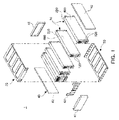
- FIG. 1 is a schematic exploded perspective view illustrating a battery module according to an exemplary embodiment in the present disclosure
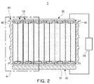
- FIG. 2 is a schematic cross-sectional view illustrating the battery module illustrated in FIG. 1
- FIG. 3 is an enlarged view illustrating region A of the battery module illustrated in FIG. 2 .
- a battery module 1 may include a plurality of sub-modules 10, a cooling unit 20, and a heating unit 30.
- the battery module 1 may further include a housing 40 supporting the plurality of sub-modules 10, the cooling unit 20, and the heating unit 30.
- Each of the plurality of sub-modules 10 may have substantially hexahedral structure, and may be arranged in a single direction.
- Each sub-module 10 may include a secondary lithium battery or a secondary nickel-hydride battery that may be charged or discharged.
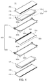
- FIGS. 4 and 5 schematically illustrate the sub-module 10.
- FIG. 4 is a schematic exploded perspective view illustrating the sub-module 10
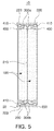
- FIG. 5 is a cross-sectional view of the sub-module 10.
- the sub-module 10 may include a pair of battery cells 100, a heat transfer member 200 interposed between the pair of battery cells 100, a frame member 300 supporting the pair of battery cells 100 and the heat transfer member 200, and a pair of pad members 400 fastened to the frame member 300 to cover the pair of battery cells 100.
- Each of the battery cells 100 may include a battery case 110 and an electrode tab 120 externally extending from the battery case 110 for connection of a power source.
- the electrode tab 120 may be connected to an electrode assembly (not illustrated) disposed inside the battery case 110.
- Each of the battery cells 100 may have, for example, a pouch structure, but is not limited thereto.
- each of the battery cells 100 may also have a quadrangle structure.
- the exemplary embodiment describes each of the battery cells 100 having a pouch structure.
- the battery case 110 may be formed by processing a surface of a metal layer including, for example, aluminum (Al) to be insulated.
- a modified polypropylene that is, a polymer resin, for example, cast polypropylene (CPP)
- CPP cast polypropylene
- PET polyethylene terephthalate
- the electrode tab 120 may include an anode tab 120a and a cathode tab 120b.
- the anode tab 120a and the cathode tab 120b may have a structure in which the anode tab 120a and the cathode tab 120b may protrude to both lateral surfaces of the battery case 110 opposing each other, respectively, to extend in different directions.
- the anode tab 120a and the cathode tab 120b may be formed of a thin plate-like metal.
- the anode tab 120a may be formed of an aluminum (Al) material
- the cathode tab 120b may be formed of a copper (Cu) material.
- the heat transfer member 200 may contact the battery cells 100 disposed on both sides thereof in a space between the battery cells 100.
- the heat transfer member 200 may have a quadrangular plate structure, and may include a body 210 disposed in the center of the frame member 300, and a pair of flanges 220 respectively connected to both ends of the body 210 to be respectively exposed to upper surfaces 300a and lower surfaces 300b of the frame member 300.
- FIGS. 6A and 6B schematically illustrate the heat transfer member 200.
- FIG. 6A is a schematic perspective view of the heat transfer member 200.
- FIG. 6B is a schematic cross-sectional view of the heat transfer member 200.
- the heat transfer member 200 may have a structure in which the body 210 may connect a pair of flanges 220, parallel to each other, to each other.
- the heat transfer member 200 may have a substantially I-beam structure formed by connecting central portions of surfaces of the flanges 220 opposing each other to both ends of the body 210 in a substantially vertical manner.
- Each of the flanges 220 may have a protrusion 221 protruding from a surface, and a receiving groove 222 recessed in another surface opposing the surface.
- the protrusion 221 and the receiving groove 222 may have shapes allowing for engagement with each other.
- the surface and the other surface of the flange 220 may correspond to, for example, both surfaces parallel to a length direction of the flange 220 having a rectangular shape.
- the protrusion 221 and the receiving groove 222 may extend to be parallel to each other in the length direction of the flange 220.
- the flange 220 may have a structure in which the flange 220 may sequentially engage with another flange 220 of another sub-module 10 adjacent to the sub-module 10.
- any one flange 220 may be fastened to another such that the protrusion 221 may engage with another receiving groove 222 of another flange 220 adjacent to the flange 220.
- the plurality of sub-modules 10 may have a structure in which the respective flanges 220 may be sequentially connected to each other.
- the flange 220 may have fastening grooves 223 recessed to a certain depth in the surface of the flange 220 connected to the body 210.
- the fastening grooves 223 may be symmetrical to each other based on the body 210 in the center of the surface of the flange 220.
- the fastening groove 223 may extend in the length direction of the flange 220.
- the heat transfer member 200 may be formed of a material having high thermal conductivity, for example, a metal material.
- the material of the heat transfer member 200 is not, however, limited thereto.
- the frame member 300 may include a first frame 310 and a second frame 320, and may have a structure in which the first frame 310 and the second frame 320 may be attached to both sides of the heat transfer member 200 with the heat transfer member 200 interposed therebetween.
- the frame member 300 may include a pair of lateral surfaces 300c respectively connecting both ends of each of the upper surfaces 300a to those of each of the lower surfaces 300b to have a hollow quadrangular ring shape.
- the frame member 300 may be configured to include four surfaces surrounding the outer peripheral portion of each of the battery cells 100.
- the frame member 300 may have the body 210 of the heat transfer member 200 disposed in the center thereof to extend across a space between the upper surfaces 300a and the lower surfaces 300b.
- the upper and lower surfaces 300a and 300b of the frame member 300 may have the flanges 220 respectively disposed thereon to be exposed externally from the upper and lower surfaces 300a and 300b.
- the pair of the pad members 400 may be respectively fastened to both sides of the frame member 300 to cover the battery cells 100.
- the pad member 400 may come in surface contact with the battery cell 100 to uniformly distribute external pressure to the surface of the battery cell 100.
- the pad member 400 may function as a buffer member that may protect the battery cell 100 and reduce an external impact thereon.
- the pad member 400 may have stop protrusions 410 formed on both ends thereof contacting the flanges 220.
- the stop protrusion 410 may extend in the length direction of the pad member 400.
- the stop protrusions 410 may be inserted into the fastening grooves 223 of the flanges 220, respectively, when fastened to the frame member 300.
- the pair of pad members 400 may be formed of a robust material to protect the pair of battery cells 100 disposed on the inside of the pad members 400.
- the cooling unit 20 and the heating unit 30 may have a structure in which the cooling unit 20 and the heating unit 30 may oppose each other with the plurality of sub-modules 10 interposed therebetween.
- the cooling unit 20 may contact one sides of the plurality of sub-modules 10, for example, upper sides, to cool the plurality of sub-modules 10.
- the cooling unit 20 may contact a portion of the flanges 220 upwardly exposed from the plurality of sub-modules 10 while the plurality of sub-modules 10 are arranged.
- the cooling unit 20 may include, for example, an indirect cooling device that may cool the plurality of sub-modules 10 through a circulating refrigerant.
- a circulating refrigerant For example, water, air, Freon, ammonia, a sulfur dioxide, or a methyl chloride may be used as a refrigerant.
- the cooling unit 20 and the plurality of sub-modules 10 may have a further heat sink pad (not illustrated) interposed therebetween, if necessary.
- the heating unit 30 may contact other sides, for example, lower sides, opposing the one sides of the plurality of sub-modules 10 to heat the plurality of sub-modules 10.
- the heating unit 30 may contact portions of the flanges 220 downwardly exposed from the plurality of sub-modules 10 while the plurality of sub-modules 10 are arranged.
- the heating unit 30 may include, for example, a heater jacket having an internal heating coil.
- the heating unit 30 and the plurality of sub-modules 10 may have a thermal conductivity pad 31 interposed therebetween for a uniform distribution of heat.
- the thermal conductivity pad 31 may be selectively interposed therebetween, and may also be removed according to an exemplary embodiment.
- the cooling unit 20 and the heating unit 30 may be connected to a control unit 50 to selectively operate, if necessary. For example, an operator may selectively operate any one of the cooling unit 20 and the heating unit 30 through the control unit 50 to cool or heat the plurality of sub-modules 10.
- the operator may drive the heating unit 30 to heat the plurality of sub-modules 10, raising the temperature of the battery module 1 to the appropriate temperature.
- the operator may drive the cooling unit 20 to cool the plurality of sub-modules 10, lowering the temperature of the battery module 1 to the appropriate temperature.
- the housing 40 may support the plurality of sub-modules 10, the cooling unit 20, and the heating unit 30.
- the housing 40 may include a pair of end plates 41 and a pair of covers 42.
- the pair of end plates 41 may be respectively disposed on both ends of the plurality of sub-modules 10, arranged in a single direction, that is, a width direction.
- the pair of covers 42 may be respectively disposed on both ends of the plurality of sub-modules 10 in a length direction of the sub-modules 10.
- the plurality of sub-modules 10 may be surrounded by the pair of end plates 41 and the pair of covers 42 to be supported thereby.
- the plurality of sub-modules 10 may be electrically connected to each other through a bus bar 43.
- the bus bar 43 may be interposed between the plurality of sub-modules 10 and the covers 42.
- the bus bar 43 may be connected to the electrode tabs 120 of the plurality of sub-modules 10.
- the battery module 1 may have a structure in which both ends of the heat transfer member 200 having the I-beam shape and passing through the sub-modules 10 in a vertical direction may be connected to the cooling unit 20 and the heating unit 30, respectively.
- the battery module 1 may thus be cooled or heated through selective driving of the cooling unit 20 or the heating unit 30.
- a battery module that may maintain an appropriate temperature thereof through selective cooling or heating of the battery module, if necessary, may be provided.
Landscapes
- Chemical & Material Sciences (AREA)
- Chemical Kinetics & Catalysis (AREA)
- Electrochemistry (AREA)
- General Chemical & Material Sciences (AREA)
- Engineering & Computer Science (AREA)
- Manufacturing & Machinery (AREA)
- Secondary Cells (AREA)
- Battery Mounting, Suspending (AREA)
Abstract
Description
- This application claims benefit of priority to Korean Patent Application No.
10-2015-0127366 filed on September 9, 2015 - The present disclosure relates to a battery module.
- Recently, high-output battery modules using a non-aqueous electrolyte solution having a high-energy density have been developed. Such high-output battery modules have been implemented to have high levels of capacity by connecting a plurality of battery cells to each other in series or parallel to be used as a power source for a device that requires high power, such as an electric or hybrid vehicle.
- The efficiency and performance of the battery modules depend on temperatures thereof. For example, when a battery module is discharged at high temperatures, the lifespan thereof is significantly reduced. Further, the charging and discharging performance of a battery module are reduced at low temperatures until the temperature of the battery module reaches a required temperature.
- An aspect of the present disclosure may provide a method of maintaining a battery module at an appropriate temperature by selectively cooling or heating the battery module, if necessary.
- According to an aspect of the present disclosure, a battery module may include: a plurality of sub-modules arranged in a single direction; a cooling unit contacting one sides of the plurality of sub-modules to cool the plurality of sub-modules; and a heating unit contacting other sides opposing the one sides of the plurality of sub-modules to heat the plurality of sub-modules.
- Each of the plurality of sub-modules may include a pair of battery cells, a heat transfer member interposed between the pair of battery cells, a frame member supporting the pair of battery cells and the heat transfer member, and a pair of pad members fastened to the frame member to cover the pair of battery cells.
- The heat transfer member may include a body disposed in the center of the frame member, and flanges respectively connected to both ends of the body to be respectively exposed to upper and lower surfaces of the frame member.
- The heat transfer member may have an I-beam structure formed by connecting central portions of surfaces of the flanges opposing each other to both ends of the body in a substantially vertical manner.
- The frame member may have a ring shape including a pair of lateral surfaces respectively connecting both ends of each of the upper and lower surfaces to each other, and the body of the heat transfer member may extend across a space between the upper and lower surfaces in the center of the frame member.
- Each of the flanges may have a protrusion protruding from a surface and a receiving groove recessed in another surface, and the protrusion and the receiving groove may have shapes allowing for engagement with each other.
- The protrusion and the receiving groove may extend in a length direction of each of the flanges.
- Each of the flanges may have fastening grooves recessed in a surface connected to the body.
- The fastening grooves may be symmetrical to each other based on the body, and may extend in a length direction of each of the flanges.
- The battery module may further include a housing supporting the plurality of sub-modules, the cooling unit, and the heating unit.
- The above and other aspects, features, and advantages of the present disclosure will be more clearly understood from the following detailed description taken in conjunction with the accompanying drawings, in which:
-
FIG. 1 is a schematic exploded perspective view illustrating a battery module according to an exemplary embodiment in the present disclosure; -
FIG. 2 is a schematic cross-sectional view illustrating the battery module illustrated inFIG. 1 ; -
FIG. 3 is an enlarged cross-sectional view illustrating region A of the battery module illustrated inFIG. 2 ; -
FIG. 4 is a schematic exploded perspective view illustrating a sub-module of the battery module according to the exemplary embodiment in the present disclosure; -
FIG. 5 is a schematic cross-sectional view illustrating the sub-module illustrated inFIG. 4 ; -
FIG. 6A is a schematic perspective view illustrating a heat transfer member included in the sub-module according to the exemplary embodiment in the present disclosure; and -
FIG. 6B is a schematic cross-sectional view illustrating the heat transfer member included in the sub-module according to the exemplary embodiment. - Hereinafter, embodiments of the present disclosure will be described as follows with reference to the attached drawings.
- The present disclosure may, however, be exemplified in many different forms and should not be construed as being limited to the specific embodiments set forth herein. Rather, these embodiments are provided so that this disclosure will be thorough and complete, and will fully convey the scope of the disclosure to those skilled in the art.
- Throughout the specification, it will be understood that when an element, such as a layer, region or wafer (substrate), is referred to as being "on," "connected to," or "coupled to" another element, it can be directly "on," "connected to," or "coupled to" the other element or other elements intervening therebetween may be present. In contrast, when an element is referred to as being "directly on," "directly connected to," or "directly coupled to" another element, there may be no elements or layers intervening therebetween. Like numerals refer to like elements throughout. As used herein, the term "and/or" includes any and all combinations of one or more of the associated listed items.
- It will be apparent that though the terms first, second, third, etc. may be used herein to describe various members, components, regions, layers and/or sections, these members, components, regions, layers and/or sections should not be limited by these terms. These terms are only used to distinguish one member, component, region, layer or section from another region, layer or section. Thus, a first member, component, region, layer or section discussed below could be termed a second member, component, region, layer or section without departing from the teachings of the exemplary embodiments.
- Spatially relative terms, such as "above," "upper," "below," and "lower" and the like, may be used herein for ease of description to describe one element's relationship to another element(s) as shown in the figures. It will be understood that the spatially relative terms are intended to encompass different orientations of the device in use or operation in addition to the orientation depicted in the figures. For example, if the device in the figures is turned over, elements described as "above," or "upper" other elements would then be oriented "below," or "lower" the other elements or features. Thus, the term "above" can encompass both the above and below orientations depending on a particular direction of the figures. The device may be otherwise oriented (rotated 90 degrees or at other orientations) and the spatially relative descriptors used herein may be interpreted accordingly.
- The terminology used herein describes particular embodiments only, and the present disclosure is not limited thereby. As used herein, the singular forms "a," "an," and "the" are intended to include the plural forms as well, unless the context clearly indicates otherwise. It will be further understood that the terms "comprises," and/or "comprising" when used in this specification, specify the presence of stated features, integers, steps, operations, members, elements, and/or groups thereof, but do not preclude the presence or addition of one or more other features, integers, steps, operations, members, elements, and/or groups thereof.
- Hereinafter, embodiments of the present disclosure will be described with reference to schematic views illustrating embodiments of the present disclosure. In the drawings, for example, due to manufacturing techniques and/or tolerances, modifications of the shape shown may be estimated. Thus, embodiments of the present disclosure should not be construed as being limited to the particular shapes of regions shown herein, for example, and may include changes in shapes resulting from manufacturing errors. The following embodiments may also be constituted by one or a combination thereof.
- The contents of the present disclosure described below may have a variety of configurations and only a required configuration is proposed herein, but the present disclosure is not limited thereto.
- Referring to
FIGS. 1 through 3 , a battery module according to an exemplary embodiment in the present disclosure will be described.FIG. 1 is a schematic exploded perspective view illustrating a battery module according to an exemplary embodiment in the present disclosure;FIG. 2 is a schematic cross-sectional view illustrating the battery module illustrated inFIG. 1 ; andFIG. 3 is an enlarged view illustrating region A of the battery module illustrated inFIG. 2 . - Referring to
FIGS. 1 through 3 , abattery module 1 according to an exemplary embodiment in the present disclosure may include a plurality ofsub-modules 10, acooling unit 20, and aheating unit 30. Thebattery module 1 may further include ahousing 40 supporting the plurality ofsub-modules 10, thecooling unit 20, and theheating unit 30. - Each of the plurality of
sub-modules 10 may have substantially hexahedral structure, and may be arranged in a single direction. Eachsub-module 10 may include a secondary lithium battery or a secondary nickel-hydride battery that may be charged or discharged. -
FIGS. 4 and5 schematically illustrate the sub-module 10.FIG. 4 is a schematic exploded perspective view illustrating the sub-module 10, andFIG. 5 is a cross-sectional view of the sub-module 10. - Referring to
FIGS. 4 and5 , the sub-module 10 may include a pair ofbattery cells 100, aheat transfer member 200 interposed between the pair ofbattery cells 100, aframe member 300 supporting the pair ofbattery cells 100 and theheat transfer member 200, and a pair ofpad members 400 fastened to theframe member 300 to cover the pair ofbattery cells 100. - Each of the
battery cells 100 may include abattery case 110 and anelectrode tab 120 externally extending from thebattery case 110 for connection of a power source. Theelectrode tab 120 may be connected to an electrode assembly (not illustrated) disposed inside thebattery case 110. - Each of the
battery cells 100 may have, for example, a pouch structure, but is not limited thereto. For example, each of thebattery cells 100 may also have a quadrangle structure. The exemplary embodiment describes each of thebattery cells 100 having a pouch structure. - The
battery case 110 may be formed by processing a surface of a metal layer including, for example, aluminum (Al) to be insulated. For the insulation processing, a modified polypropylene, that is, a polymer resin, for example, cast polypropylene (CPP), may be coated to form a thermal bonding layer, and a resin material such as a nylon or a polyethylene terephthalate (PET) may be formed on an outer surface of the modified polypropylene. - The
electrode tab 120 may include ananode tab 120a and acathode tab 120b. Theanode tab 120a and thecathode tab 120b may have a structure in which theanode tab 120a and thecathode tab 120b may protrude to both lateral surfaces of thebattery case 110 opposing each other, respectively, to extend in different directions. - The
anode tab 120a and thecathode tab 120b may be formed of a thin plate-like metal. For example, theanode tab 120a may be formed of an aluminum (Al) material, and thecathode tab 120b may be formed of a copper (Cu) material. - The
heat transfer member 200 may contact thebattery cells 100 disposed on both sides thereof in a space between thebattery cells 100. - The
heat transfer member 200 may have a quadrangular plate structure, and may include abody 210 disposed in the center of theframe member 300, and a pair offlanges 220 respectively connected to both ends of thebody 210 to be respectively exposed toupper surfaces 300a andlower surfaces 300b of theframe member 300. -
FIGS. 6A and 6B schematically illustrate theheat transfer member 200.FIG. 6A is a schematic perspective view of theheat transfer member 200.FIG. 6B is a schematic cross-sectional view of theheat transfer member 200. - Referring to
FIGS. 6A and 6B , theheat transfer member 200 may have a structure in which thebody 210 may connect a pair offlanges 220, parallel to each other, to each other. For example, theheat transfer member 200 may have a substantially I-beam structure formed by connecting central portions of surfaces of theflanges 220 opposing each other to both ends of thebody 210 in a substantially vertical manner. - Each of the
flanges 220 may have aprotrusion 221 protruding from a surface, and a receivinggroove 222 recessed in another surface opposing the surface. Theprotrusion 221 and the receivinggroove 222 may have shapes allowing for engagement with each other. Here, the surface and the other surface of theflange 220 may correspond to, for example, both surfaces parallel to a length direction of theflange 220 having a rectangular shape. Thus, theprotrusion 221 and the receivinggroove 222 may extend to be parallel to each other in the length direction of theflange 220. - Referring to
FIGS. 3 and6B , theflange 220 may have a structure in which theflange 220 may sequentially engage with anotherflange 220 of another sub-module 10 adjacent to the sub-module 10. In detail, any oneflange 220 may be fastened to another such that theprotrusion 221 may engage with another receivinggroove 222 of anotherflange 220 adjacent to theflange 220. In such a manner, the plurality ofsub-modules 10 may have a structure in which therespective flanges 220 may be sequentially connected to each other. - The
flange 220 may havefastening grooves 223 recessed to a certain depth in the surface of theflange 220 connected to thebody 210. Thefastening grooves 223 may be symmetrical to each other based on thebody 210 in the center of the surface of theflange 220. Thefastening groove 223 may extend in the length direction of theflange 220. - The
heat transfer member 200 may be formed of a material having high thermal conductivity, for example, a metal material. The material of theheat transfer member 200 is not, however, limited thereto. - The
frame member 300 may include afirst frame 310 and asecond frame 320, and may have a structure in which thefirst frame 310 and thesecond frame 320 may be attached to both sides of theheat transfer member 200 with theheat transfer member 200 interposed therebetween. - The
frame member 300 may include a pair oflateral surfaces 300c respectively connecting both ends of each of theupper surfaces 300a to those of each of thelower surfaces 300b to have a hollow quadrangular ring shape. For example, theframe member 300 may be configured to include four surfaces surrounding the outer peripheral portion of each of thebattery cells 100. - The
frame member 300 may have thebody 210 of theheat transfer member 200 disposed in the center thereof to extend across a space between theupper surfaces 300a and thelower surfaces 300b. The upper andlower surfaces frame member 300 may have theflanges 220 respectively disposed thereon to be exposed externally from the upper andlower surfaces - The pair of the
pad members 400 may be respectively fastened to both sides of theframe member 300 to cover thebattery cells 100. - The
pad member 400 may come in surface contact with thebattery cell 100 to uniformly distribute external pressure to the surface of thebattery cell 100. For example, thepad member 400 may function as a buffer member that may protect thebattery cell 100 and reduce an external impact thereon. - The
pad member 400 may have stopprotrusions 410 formed on both ends thereof contacting theflanges 220. Thestop protrusion 410 may extend in the length direction of thepad member 400. - Referring to
FIG. 5 , thestop protrusions 410 may be inserted into thefastening grooves 223 of theflanges 220, respectively, when fastened to theframe member 300. - The pair of
pad members 400 may be formed of a robust material to protect the pair ofbattery cells 100 disposed on the inside of thepad members 400. - Referring again to
FIGS. 1 and2 , the coolingunit 20 and theheating unit 30 may have a structure in which thecooling unit 20 and theheating unit 30 may oppose each other with the plurality ofsub-modules 10 interposed therebetween. - The cooling
unit 20 may contact one sides of the plurality ofsub-modules 10, for example, upper sides, to cool the plurality ofsub-modules 10. - As illustrated in the drawings, the cooling
unit 20 may contact a portion of theflanges 220 upwardly exposed from the plurality ofsub-modules 10 while the plurality ofsub-modules 10 are arranged. - The cooling
unit 20 may include, for example, an indirect cooling device that may cool the plurality ofsub-modules 10 through a circulating refrigerant. For example, water, air, Freon, ammonia, a sulfur dioxide, or a methyl chloride may be used as a refrigerant. - The cooling
unit 20 and the plurality ofsub-modules 10 may have a further heat sink pad (not illustrated) interposed therebetween, if necessary. - The
heating unit 30 may contact other sides, for example, lower sides, opposing the one sides of the plurality ofsub-modules 10 to heat the plurality ofsub-modules 10. - As illustrated in the drawings, the
heating unit 30 may contact portions of theflanges 220 downwardly exposed from the plurality ofsub-modules 10 while the plurality ofsub-modules 10 are arranged. - The
heating unit 30 may include, for example, a heater jacket having an internal heating coil. - The
heating unit 30 and the plurality ofsub-modules 10 may have athermal conductivity pad 31 interposed therebetween for a uniform distribution of heat. Thethermal conductivity pad 31 may be selectively interposed therebetween, and may also be removed according to an exemplary embodiment. - The cooling
unit 20 and theheating unit 30 may be connected to acontrol unit 50 to selectively operate, if necessary. For example, an operator may selectively operate any one of the coolingunit 20 and theheating unit 30 through thecontrol unit 50 to cool or heat the plurality ofsub-modules 10. - For example, when low temperatures in wintertime cause a temperature of the
battery module 1 to be decreased below an appropriate temperature, the operator may drive theheating unit 30 to heat the plurality ofsub-modules 10, raising the temperature of thebattery module 1 to the appropriate temperature. Further, when high temperatures in summertime cause the temperature of thebattery module 1 to be excessively high, the operator may drive the coolingunit 20 to cool the plurality ofsub-modules 10, lowering the temperature of thebattery module 1 to the appropriate temperature. - The
housing 40 may support the plurality ofsub-modules 10, the coolingunit 20, and theheating unit 30. Thehousing 40 may include a pair ofend plates 41 and a pair ofcovers 42. - The pair of
end plates 41 may be respectively disposed on both ends of the plurality ofsub-modules 10, arranged in a single direction, that is, a width direction. The pair ofcovers 42 may be respectively disposed on both ends of the plurality ofsub-modules 10 in a length direction of the sub-modules 10. Thus, the plurality ofsub-modules 10 may be surrounded by the pair ofend plates 41 and the pair ofcovers 42 to be supported thereby. - The plurality of
sub-modules 10 may be electrically connected to each other through abus bar 43. Thebus bar 43 may be interposed between the plurality ofsub-modules 10 and thecovers 42. Thebus bar 43 may be connected to theelectrode tabs 120 of the plurality ofsub-modules 10. - As such, the
battery module 1 according to the exemplary embodiment may have a structure in which both ends of theheat transfer member 200 having the I-beam shape and passing through the sub-modules 10 in a vertical direction may be connected to thecooling unit 20 and theheating unit 30, respectively. Thebattery module 1 may thus be cooled or heated through selective driving of the coolingunit 20 or theheating unit 30. - As set forth above, according to exemplary embodiments in the present disclosure, a battery module that may maintain an appropriate temperature thereof through selective cooling or heating of the battery module, if necessary, may be provided.
- While embodiments have been shown and described above, it will be apparent to those skilled in the art that modifications and variations could be made without departing from the scope of the present disclosure as defined by the appended claims.
Claims (10)
- A battery module comprising:a plurality of sub-modules arranged in a direction;a cooling unit contacting one sides of the plurality of sub-modules to cool the plurality of sub-modules; anda heating unit contacting other sides opposing the one sides of the plurality of sub-modules to heat the plurality of sub-modules.
- The battery module of claim 1, wherein each of the plurality of sub-modules includes a pair of battery cells, a heat transfer member interposed between the pair of battery cells, a frame member supporting the pair of battery cells and the heat transfer member, and a pair of pad members fastened to the frame member to cover the pair of battery cells.
- The battery module of claim 2, wherein the heat transfer member includes a body disposed in the center of the frame member, and flanges respectively connected to both ends of the body to be respectively exposed to upper and lower surfaces of the frame member.
- The battery module of claim 3, wherein the heat transfer member has an I-beam structure formed by connecting central portions of surfaces of the flanges opposing each other to both ends of the body in a substantially vertical manner.
- The battery module of claim 3, wherein the frame member has a ring shape including a pair of lateral surfaces respectively connecting both ends of each of the upper and lower surfaces to each other, and the body of the heat transfer member extends across a space between the upper and lower surfaces in the center of the frame member.
- The battery module of claim 3, wherein each of the flanges has a protrusion protruding from a surface and a receiving groove recessed in another surface, and the protrusion and the receiving groove have shapes allowing for engagement with each other.
- The battery module of claim 6, wherein the protrusion and the receiving groove extend in a length direction of each of the flanges.
- The battery module of claim 3, wherein each of the flanges has fastening grooves recessed in a surface connected to the body.
- The battery module of claim 8, wherein the fastening grooves are symmetrical to each other based on the body, and extend in a length direction of each of the flanges.
- The battery module of claim 1, further comprising a housing supporting the plurality of sub-modules, the cooling unit, and the heating unit.
Applications Claiming Priority (1)
| Application Number | Priority Date | Filing Date | Title |
|---|---|---|---|
| KR1020150127366A KR102284339B1 (en) | 2015-09-09 | 2015-09-09 | Battery module |
Publications (2)
| Publication Number | Publication Date |
|---|---|
| EP3142184A1 true EP3142184A1 (en) | 2017-03-15 |
| EP3142184B1 EP3142184B1 (en) | 2024-06-26 |
Family
ID=56801449
Family Applications (1)
| Application Number | Title | Priority Date | Filing Date |
|---|---|---|---|
| EP16185758.6A Active EP3142184B1 (en) | 2015-09-09 | 2016-08-25 | Battery module |
Country Status (5)
| Country | Link |
|---|---|
| US (2) | US10886510B2 (en) |
| EP (1) | EP3142184B1 (en) |
| JP (1) | JP2017054807A (en) |
| KR (1) | KR102284339B1 (en) |
| CN (1) | CN106972216B (en) |
Cited By (1)
| Publication number | Priority date | Publication date | Assignee | Title |
|---|---|---|---|---|
| EP4109629A4 (en) * | 2020-10-22 | 2024-03-06 | Envision AESC Japan Ltd. | Battery module, battery device, and method for manufacturing battery module |
Families Citing this family (13)
| Publication number | Priority date | Publication date | Assignee | Title |
|---|---|---|---|---|
| KR102284339B1 (en) * | 2015-09-09 | 2021-08-04 | 에스케이이노베이션 주식회사 | Battery module |
| KR102389469B1 (en) * | 2017-07-26 | 2022-04-22 | 주식회사 엘지에너지솔루션 | Battery pack |
| WO2019039116A1 (en) * | 2017-08-22 | 2019-02-28 | 日立オートモティブシステムズ株式会社 | Battery pack |
| KR102397774B1 (en) * | 2017-11-14 | 2022-05-13 | 주식회사 엘지에너지솔루션 | Battery module and battery pack having the same |
| DE102018133391A1 (en) * | 2017-12-26 | 2019-06-27 | Sk Innovation Co., Ltd. | Battery module and manufacturing method thereof |
| US20190198952A1 (en) * | 2017-12-26 | 2019-06-27 | Sk Innovation Co., Ltd. | Battery module and manufacturing method thereof |
| KR102655349B1 (en) * | 2018-06-28 | 2024-04-05 | 에스케이온 주식회사 | Battery pack having cooling device |
| KR102373774B1 (en) * | 2018-08-21 | 2022-03-14 | 에스케이온 주식회사 | Battery Module and Battery Pack including the same |
| US11894532B2 (en) * | 2018-08-21 | 2024-02-06 | Sk On Co., Ltd. | Battery module and manufacturing method thereof |
| CN210006793U (en) * | 2019-07-04 | 2020-01-31 | 江苏时代新能源科技有限公司 | Battery module |
| KR20210037885A (en) * | 2019-09-30 | 2021-04-07 | 에스케이이노베이션 주식회사 | Battery Module |
| KR20210133417A (en) * | 2020-04-29 | 2021-11-08 | 에너테크인터내셔널 주식회사 | battery pack for electric vehicle including electric heater |
| KR102586730B1 (en) * | 2021-05-27 | 2023-10-10 | 주식회사 현대케피코 | Vehicle high voltage battery module heating device |
Citations (4)
| Publication number | Priority date | Publication date | Assignee | Title |
|---|---|---|---|---|
| JP2008035581A (en) * | 2006-07-26 | 2008-02-14 | Toyota Motor Corp | Power supply device of vehicle |
| FR2988918A3 (en) * | 2012-03-27 | 2013-10-04 | Renault Sa | Integral module for cooling and heating traction battery of e.g. electric car, has heat pipe comprising internal section extending inside from plate and in contact with alignment and external section in contact with fluid outside of module |
| US20150079443A1 (en) * | 2007-11-07 | 2015-03-19 | Enerdel, Inc. | Battery assembly with temperature control device |
| CN204464348U (en) * | 2014-04-03 | 2015-07-08 | 株式会社Lg化学 | Battery pack and battery operating system |
Family Cites Families (15)
| Publication number | Priority date | Publication date | Assignee | Title |
|---|---|---|---|---|
| KR20100095457A (en) * | 2007-12-05 | 2010-08-30 | 에네르델, 인코포레이티드 | Battery assembly with temperature control device |
| WO2011073424A1 (en) * | 2009-12-18 | 2011-06-23 | Magna E-Car Systems Gmbh & Co Og | Cooling/heating element for an accumulator |
| KR101903492B1 (en) * | 2010-08-12 | 2018-10-02 | 후루카와 덴끼고교 가부시키가이샤 | Battery temperature regulation system and battery temperature regulation unit |
| DE102012101141A1 (en) * | 2012-02-14 | 2013-08-14 | Elringklinger Ag | Cooling fin module for lithium ion battery that is utilized for driving motor car, has cooling fin metal plate comprising heat-collection and release regions that are integrally connected with one another at bent section |
| JP2013242979A (en) * | 2012-05-18 | 2013-12-05 | Hitachi Ltd | Power storage module and manufacturing method therefor |
| KR20140007080A (en) | 2012-06-27 | 2014-01-17 | 현대자동차주식회사 | High voltage battery pack for vehicle |
| JP6043555B2 (en) * | 2012-09-12 | 2016-12-14 | 昭和電工株式会社 | Battery cooling structure |
| KR101619422B1 (en) * | 2012-10-12 | 2016-05-10 | 주식회사 엘지화학 | Electrode Assembly with Improved Safety, and Battery Cell, Battery Pack and Device Comprising the Same |
| KR101730961B1 (en) | 2013-01-04 | 2017-04-27 | 삼성에스디아이 주식회사 | Battery module having heat insulating member |
| US9525195B2 (en) * | 2013-07-30 | 2016-12-20 | Johnson Controls Technology Corporation | Remanufacturing methods for battery module |
| US9379365B2 (en) | 2013-09-12 | 2016-06-28 | GM Global Technology Operations LLC | Cell frame for EREV GEN2 battery module (liquid fin concept) with heat exchanger (HEX) insertion features |
| KR101658589B1 (en) | 2013-09-30 | 2016-09-30 | 주식회사 엘지화학 | Battery Module Having Metal Printed Circuit Board |
| KR101544548B1 (en) * | 2013-10-24 | 2015-08-13 | 엘지전자 주식회사 | Cell Module Assembly |
| US9666843B2 (en) * | 2014-07-30 | 2017-05-30 | Ford Global Technologies, Llc | Array frame design for electrified vehicle battery arrays |
| KR102284339B1 (en) * | 2015-09-09 | 2021-08-04 | 에스케이이노베이션 주식회사 | Battery module |
-
2015
- 2015-09-09 KR KR1020150127366A patent/KR102284339B1/en active IP Right Grant
-
2016
- 2016-08-19 JP JP2016161396A patent/JP2017054807A/en active Pending
- 2016-08-25 EP EP16185758.6A patent/EP3142184B1/en active Active
- 2016-08-26 US US15/249,171 patent/US10886510B2/en active Active
- 2016-09-08 CN CN201610811620.2A patent/CN106972216B/en active Active
-
2020
- 2020-12-30 US US17/138,328 patent/US11462797B2/en active Active
Patent Citations (4)
| Publication number | Priority date | Publication date | Assignee | Title |
|---|---|---|---|---|
| JP2008035581A (en) * | 2006-07-26 | 2008-02-14 | Toyota Motor Corp | Power supply device of vehicle |
| US20150079443A1 (en) * | 2007-11-07 | 2015-03-19 | Enerdel, Inc. | Battery assembly with temperature control device |
| FR2988918A3 (en) * | 2012-03-27 | 2013-10-04 | Renault Sa | Integral module for cooling and heating traction battery of e.g. electric car, has heat pipe comprising internal section extending inside from plate and in contact with alignment and external section in contact with fluid outside of module |
| CN204464348U (en) * | 2014-04-03 | 2015-07-08 | 株式会社Lg化学 | Battery pack and battery operating system |
Cited By (1)
| Publication number | Priority date | Publication date | Assignee | Title |
|---|---|---|---|---|
| EP4109629A4 (en) * | 2020-10-22 | 2024-03-06 | Envision AESC Japan Ltd. | Battery module, battery device, and method for manufacturing battery module |
Also Published As
| Publication number | Publication date |
|---|---|
| CN106972216B (en) | 2021-07-06 |
| US20210119293A1 (en) | 2021-04-22 |
| KR20170030667A (en) | 2017-03-20 |
| KR102284339B1 (en) | 2021-08-04 |
| CN106972216A (en) | 2017-07-21 |
| US20170069887A1 (en) | 2017-03-09 |
| EP3142184B1 (en) | 2024-06-26 |
| JP2017054807A (en) | 2017-03-16 |
| US11462797B2 (en) | 2022-10-04 |
| US10886510B2 (en) | 2021-01-05 |
Similar Documents
| Publication | Publication Date | Title |
|---|---|---|
| US11462797B2 (en) | Battery module with selective temperature control | |
| US9219261B2 (en) | Battery pack | |
| KR102081396B1 (en) | Battery module, battery pack comprising the battery module and vehicle comprising the battery pack | |
| US11495849B2 (en) | Battery module including a housing floor with integrated cooling | |
| US9196938B2 (en) | Battery module | |
| US10950905B2 (en) | Battery module, and battery pack and vehicle comprising the same | |
| KR102067710B1 (en) | Battery module, battery pack comprising the battery module and vehicle comprising the battery pack | |
| US10027002B2 (en) | Vehicle battery pack with improved cooling efficiency | |
| JP2006278330A (en) | Secondary battery module | |
| US20140234691A1 (en) | Battery module with novel structure | |
| US20150194714A1 (en) | Battery module assembly | |
| KR100696694B1 (en) | Secondary battery module | |
| US10804578B2 (en) | Battery module, battery pack and vehicle having same | |
| WO2011092773A1 (en) | Cell module | |
| US20120129030A1 (en) | Battery Pack | |
| JP2004362879A (en) | Collective battery | |
| US20170110773A1 (en) | Battery module including a cooling plate with embedded cooling tubes | |
| JP6124512B2 (en) | Battery module | |
| KR101496523B1 (en) | Radiant heat plate for battery cell | |
| EP3067962B1 (en) | Battery pack | |
| EP2631986B1 (en) | Battery module | |
| KR20120048262A (en) | Battery module | |
| KR102061292B1 (en) | Battery module, battery pack comprising the battery module and vehicle comprising the battery pack | |
| JP5904109B2 (en) | Power storage module and temperature control structure of power storage module | |
| JP2016181408A (en) | Battery module |
Legal Events
| Date | Code | Title | Description |
|---|---|---|---|
| PUAI | Public reference made under article 153(3) epc to a published international application that has entered the european phase |
Free format text: ORIGINAL CODE: 0009012 |
|
| STAA | Information on the status of an ep patent application or granted ep patent |
Free format text: STATUS: THE APPLICATION HAS BEEN PUBLISHED |
|
| AK | Designated contracting states |
Kind code of ref document: A1 Designated state(s): AL AT BE BG CH CY CZ DE DK EE ES FI FR GB GR HR HU IE IS IT LI LT LU LV MC MK MT NL NO PL PT RO RS SE SI SK SM TR |
|
| AX | Request for extension of the european patent |
Extension state: BA ME |
|
| STAA | Information on the status of an ep patent application or granted ep patent |
Free format text: STATUS: REQUEST FOR EXAMINATION WAS MADE |
|
| 17P | Request for examination filed |
Effective date: 20170831 |
|
| RBV | Designated contracting states (corrected) |
Designated state(s): AL AT BE BG CH CY CZ DE DK EE ES FI FR GB GR HR HU IE IS IT LI LT LU LV MC MK MT NL NO PL PT RO RS SE SI SK SM TR |
|
| STAA | Information on the status of an ep patent application or granted ep patent |
Free format text: STATUS: EXAMINATION IS IN PROGRESS |
|
| 17Q | First examination report despatched |
Effective date: 20180813 |
|
| STAA | Information on the status of an ep patent application or granted ep patent |
Free format text: STATUS: EXAMINATION IS IN PROGRESS |
|
| STAA | Information on the status of an ep patent application or granted ep patent |
Free format text: STATUS: EXAMINATION IS IN PROGRESS |
|
| RAP1 | Party data changed (applicant data changed or rights of an application transferred) |
Owner name: SK ON CO., LTD. |
|
| P01 | Opt-out of the competence of the unified patent court (upc) registered |
Effective date: 20230602 |
|
| RIC1 | Information provided on ipc code assigned before grant |
Ipc: H01M 10/6556 20140101ALN20231220BHEP Ipc: H01M 50/211 20210101ALI20231220BHEP Ipc: H01M 10/613 20140101ALI20231220BHEP Ipc: H01M 10/615 20140101ALI20231220BHEP Ipc: H01M 10/647 20140101ALI20231220BHEP Ipc: H01M 10/6555 20140101AFI20231220BHEP |
|
| GRAP | Despatch of communication of intention to grant a patent |
Free format text: ORIGINAL CODE: EPIDOSNIGR1 |
|
| STAA | Information on the status of an ep patent application or granted ep patent |
Free format text: STATUS: GRANT OF PATENT IS INTENDED |
|
| RIC1 | Information provided on ipc code assigned before grant |
Ipc: H01M 10/6556 20140101ALN20240122BHEP Ipc: H01M 50/211 20210101ALI20240122BHEP Ipc: H01M 10/613 20140101ALI20240122BHEP Ipc: H01M 10/615 20140101ALI20240122BHEP Ipc: H01M 10/647 20140101ALI20240122BHEP Ipc: H01M 10/6555 20140101AFI20240122BHEP |
|
| INTG | Intention to grant announced |
Effective date: 20240227 |
|
| GRAS | Grant fee paid |
Free format text: ORIGINAL CODE: EPIDOSNIGR3 |
|
| GRAA | (expected) grant |
Free format text: ORIGINAL CODE: 0009210 |
|
| STAA | Information on the status of an ep patent application or granted ep patent |
Free format text: STATUS: THE PATENT HAS BEEN GRANTED |
|
| AK | Designated contracting states |
Kind code of ref document: B1 Designated state(s): AL AT BE BG CH CY CZ DE DK EE ES FI FR GB GR HR HU IE IS IT LI LT LU LV MC MK MT NL NO PL PT RO RS SE SI SK SM TR |
|
| REG | Reference to a national code |
Ref country code: GB Ref legal event code: FG4D |
|
| REG | Reference to a national code |
Ref country code: CH Ref legal event code: EP |
|
| REG | Reference to a national code |
Ref country code: DE Ref legal event code: R096 Ref document number: 602016088100 Country of ref document: DE |