EP3141982A1 - Elektronische vorrichtung zur messung von eingangsdruck und verfahren zum betreiben der elektronischen vorrichtung - Google Patents
Elektronische vorrichtung zur messung von eingangsdruck und verfahren zum betreiben der elektronischen vorrichtung Download PDFInfo
- Publication number
- EP3141982A1 EP3141982A1 EP16188171.9A EP16188171A EP3141982A1 EP 3141982 A1 EP3141982 A1 EP 3141982A1 EP 16188171 A EP16188171 A EP 16188171A EP 3141982 A1 EP3141982 A1 EP 3141982A1
- Authority
- EP
- European Patent Office
- Prior art keywords
- input
- electronic device
- pressure
- display
- image
- Prior art date
- Legal status (The legal status is an assumption and is not a legal conclusion. Google has not performed a legal analysis and makes no representation as to the accuracy of the status listed.)
- Granted
Links
- 238000000034 method Methods 0.000 title claims abstract description 31
- 230000006870 function Effects 0.000 claims description 94
- 238000004891 communication Methods 0.000 description 26
- 238000012545 processing Methods 0.000 description 9
- 230000001413 cellular effect Effects 0.000 description 8
- 230000008569 process Effects 0.000 description 7
- 238000010586 diagram Methods 0.000 description 6
- 125000006850 spacer group Chemical group 0.000 description 4
- 230000000694 effects Effects 0.000 description 3
- 238000005516 engineering process Methods 0.000 description 3
- 230000036541 health Effects 0.000 description 3
- 230000003287 optical effect Effects 0.000 description 3
- WQZGKKKJIJFFOK-GASJEMHNSA-N Glucose Natural products OC[C@H]1OC(O)[C@H](O)[C@@H](O)[C@@H]1O WQZGKKKJIJFFOK-GASJEMHNSA-N 0.000 description 2
- 239000002390 adhesive tape Substances 0.000 description 2
- 230000008859 change Effects 0.000 description 2
- 238000002591 computed tomography Methods 0.000 description 2
- 230000007423 decrease Effects 0.000 description 2
- 238000001514 detection method Methods 0.000 description 2
- 238000011161 development Methods 0.000 description 2
- 230000005611 electricity Effects 0.000 description 2
- 239000008103 glucose Substances 0.000 description 2
- 230000003068 static effect Effects 0.000 description 2
- 239000000758 substrate Substances 0.000 description 2
- XLYOFNOQVPJJNP-UHFFFAOYSA-N water Substances O XLYOFNOQVPJJNP-UHFFFAOYSA-N 0.000 description 2
- RYGMFSIKBFXOCR-UHFFFAOYSA-N Copper Chemical compound [Cu] RYGMFSIKBFXOCR-UHFFFAOYSA-N 0.000 description 1
- 238000002583 angiography Methods 0.000 description 1
- 210000003423 ankle Anatomy 0.000 description 1
- 238000013473 artificial intelligence Methods 0.000 description 1
- 239000008280 blood Substances 0.000 description 1
- 210000004369 blood Anatomy 0.000 description 1
- 230000036772 blood pressure Effects 0.000 description 1
- 230000036760 body temperature Effects 0.000 description 1
- 230000010267 cellular communication Effects 0.000 description 1
- 230000006835 compression Effects 0.000 description 1
- 238000007906 compression Methods 0.000 description 1
- 238000010276 construction Methods 0.000 description 1
- 229910052802 copper Inorganic materials 0.000 description 1
- 239000010949 copper Substances 0.000 description 1
- 230000006837 decompression Effects 0.000 description 1
- -1 electricity Substances 0.000 description 1
- 239000004744 fabric Substances 0.000 description 1
- 239000000446 fuel Substances 0.000 description 1
- 230000014509 gene expression Effects 0.000 description 1
- 239000011521 glass Substances 0.000 description 1
- 238000005286 illumination Methods 0.000 description 1
- 238000003384 imaging method Methods 0.000 description 1
- 230000006698 induction Effects 0.000 description 1
- 238000009434 installation Methods 0.000 description 1
- 238000009413 insulation Methods 0.000 description 1
- 239000004973 liquid crystal related substance Substances 0.000 description 1
- 230000007774 longterm Effects 0.000 description 1
- 238000002595 magnetic resonance imaging Methods 0.000 description 1
- 238000005259 measurement Methods 0.000 description 1
- 201000002266 mite infestation Diseases 0.000 description 1
- 238000010295 mobile communication Methods 0.000 description 1
- 238000012986 modification Methods 0.000 description 1
- 230000004048 modification Effects 0.000 description 1
- 230000003252 repetitive effect Effects 0.000 description 1
- 229910052710 silicon Inorganic materials 0.000 description 1
- 239000010703 silicon Substances 0.000 description 1
- 239000007787 solid Substances 0.000 description 1
- 230000001360 synchronised effect Effects 0.000 description 1
- 229910052724 xenon Inorganic materials 0.000 description 1
- FHNFHKCVQCLJFQ-UHFFFAOYSA-N xenon atom Chemical compound [Xe] FHNFHKCVQCLJFQ-UHFFFAOYSA-N 0.000 description 1
Images


Classifications
-
- G—PHYSICS
- G06—COMPUTING; CALCULATING OR COUNTING
- G06F—ELECTRIC DIGITAL DATA PROCESSING
- G06F3/00—Input arrangements for transferring data to be processed into a form capable of being handled by the computer; Output arrangements for transferring data from processing unit to output unit, e.g. interface arrangements
- G06F3/01—Input arrangements or combined input and output arrangements for interaction between user and computer
- G06F3/048—Interaction techniques based on graphical user interfaces [GUI]
- G06F3/0487—Interaction techniques based on graphical user interfaces [GUI] using specific features provided by the input device, e.g. functions controlled by the rotation of a mouse with dual sensing arrangements, or of the nature of the input device, e.g. tap gestures based on pressure sensed by a digitiser
- G06F3/0488—Interaction techniques based on graphical user interfaces [GUI] using specific features provided by the input device, e.g. functions controlled by the rotation of a mouse with dual sensing arrangements, or of the nature of the input device, e.g. tap gestures based on pressure sensed by a digitiser using a touch-screen or digitiser, e.g. input of commands through traced gestures
-
- G—PHYSICS
- G06—COMPUTING; CALCULATING OR COUNTING
- G06F—ELECTRIC DIGITAL DATA PROCESSING
- G06F3/00—Input arrangements for transferring data to be processed into a form capable of being handled by the computer; Output arrangements for transferring data from processing unit to output unit, e.g. interface arrangements
- G06F3/01—Input arrangements or combined input and output arrangements for interaction between user and computer
- G06F3/03—Arrangements for converting the position or the displacement of a member into a coded form
- G06F3/041—Digitisers, e.g. for touch screens or touch pads, characterised by the transducing means
- G06F3/0416—Control or interface arrangements specially adapted for digitisers
-
- G—PHYSICS
- G06—COMPUTING; CALCULATING OR COUNTING
- G06F—ELECTRIC DIGITAL DATA PROCESSING
- G06F1/00—Details not covered by groups G06F3/00 - G06F13/00 and G06F21/00
- G06F1/16—Constructional details or arrangements
- G06F1/1613—Constructional details or arrangements for portable computers
- G06F1/1633—Constructional details or arrangements of portable computers not specific to the type of enclosures covered by groups G06F1/1615 - G06F1/1626
- G06F1/1637—Details related to the display arrangement, including those related to the mounting of the display in the housing
- G06F1/1641—Details related to the display arrangement, including those related to the mounting of the display in the housing the display being formed by a plurality of foldable display components
-
- G—PHYSICS
- G06—COMPUTING; CALCULATING OR COUNTING
- G06F—ELECTRIC DIGITAL DATA PROCESSING
- G06F1/00—Details not covered by groups G06F3/00 - G06F13/00 and G06F21/00
- G06F1/16—Constructional details or arrangements
- G06F1/1613—Constructional details or arrangements for portable computers
- G06F1/1633—Constructional details or arrangements of portable computers not specific to the type of enclosures covered by groups G06F1/1615 - G06F1/1626
- G06F1/1637—Details related to the display arrangement, including those related to the mounting of the display in the housing
- G06F1/1647—Details related to the display arrangement, including those related to the mounting of the display in the housing including at least an additional display
-
- G—PHYSICS
- G06—COMPUTING; CALCULATING OR COUNTING
- G06F—ELECTRIC DIGITAL DATA PROCESSING
- G06F3/00—Input arrangements for transferring data to be processed into a form capable of being handled by the computer; Output arrangements for transferring data from processing unit to output unit, e.g. interface arrangements
- G06F3/01—Input arrangements or combined input and output arrangements for interaction between user and computer
- G06F3/03—Arrangements for converting the position or the displacement of a member into a coded form
- G06F3/041—Digitisers, e.g. for touch screens or touch pads, characterised by the transducing means
- G06F3/0414—Digitisers, e.g. for touch screens or touch pads, characterised by the transducing means using force sensing means to determine a position
-
- G—PHYSICS
- G06—COMPUTING; CALCULATING OR COUNTING
- G06F—ELECTRIC DIGITAL DATA PROCESSING
- G06F3/00—Input arrangements for transferring data to be processed into a form capable of being handled by the computer; Output arrangements for transferring data from processing unit to output unit, e.g. interface arrangements
- G06F3/01—Input arrangements or combined input and output arrangements for interaction between user and computer
- G06F3/03—Arrangements for converting the position or the displacement of a member into a coded form
- G06F3/041—Digitisers, e.g. for touch screens or touch pads, characterised by the transducing means
- G06F3/044—Digitisers, e.g. for touch screens or touch pads, characterised by the transducing means by capacitive means
-
- G—PHYSICS
- G06—COMPUTING; CALCULATING OR COUNTING
- G06F—ELECTRIC DIGITAL DATA PROCESSING
- G06F3/00—Input arrangements for transferring data to be processed into a form capable of being handled by the computer; Output arrangements for transferring data from processing unit to output unit, e.g. interface arrangements
- G06F3/01—Input arrangements or combined input and output arrangements for interaction between user and computer
- G06F3/048—Interaction techniques based on graphical user interfaces [GUI]
- G06F3/0487—Interaction techniques based on graphical user interfaces [GUI] using specific features provided by the input device, e.g. functions controlled by the rotation of a mouse with dual sensing arrangements, or of the nature of the input device, e.g. tap gestures based on pressure sensed by a digitiser
- G06F3/0488—Interaction techniques based on graphical user interfaces [GUI] using specific features provided by the input device, e.g. functions controlled by the rotation of a mouse with dual sensing arrangements, or of the nature of the input device, e.g. tap gestures based on pressure sensed by a digitiser using a touch-screen or digitiser, e.g. input of commands through traced gestures
- G06F3/04883—Interaction techniques based on graphical user interfaces [GUI] using specific features provided by the input device, e.g. functions controlled by the rotation of a mouse with dual sensing arrangements, or of the nature of the input device, e.g. tap gestures based on pressure sensed by a digitiser using a touch-screen or digitiser, e.g. input of commands through traced gestures for inputting data by handwriting, e.g. gesture or text
-
- G—PHYSICS
- G06—COMPUTING; CALCULATING OR COUNTING
- G06F—ELECTRIC DIGITAL DATA PROCESSING
- G06F3/00—Input arrangements for transferring data to be processed into a form capable of being handled by the computer; Output arrangements for transferring data from processing unit to output unit, e.g. interface arrangements
- G06F3/14—Digital output to display device ; Cooperation and interconnection of the display device with other functional units
- G06F3/1423—Digital output to display device ; Cooperation and interconnection of the display device with other functional units controlling a plurality of local displays, e.g. CRT and flat panel display
-
- G—PHYSICS
- G06—COMPUTING; CALCULATING OR COUNTING
- G06F—ELECTRIC DIGITAL DATA PROCESSING
- G06F2203/00—Indexing scheme relating to G06F3/00 - G06F3/048
- G06F2203/041—Indexing scheme relating to G06F3/041 - G06F3/045
- G06F2203/04102—Flexible digitiser, i.e. constructional details for allowing the whole digitising part of a device to be flexed or rolled like a sheet of paper
-
- G—PHYSICS
- G06—COMPUTING; CALCULATING OR COUNTING
- G06F—ELECTRIC DIGITAL DATA PROCESSING
- G06F2203/00—Indexing scheme relating to G06F3/00 - G06F3/048
- G06F2203/041—Indexing scheme relating to G06F3/041 - G06F3/045
- G06F2203/04104—Multi-touch detection in digitiser, i.e. details about the simultaneous detection of a plurality of touching locations, e.g. multiple fingers or pen and finger
-
- G—PHYSICS
- G06—COMPUTING; CALCULATING OR COUNTING
- G06F—ELECTRIC DIGITAL DATA PROCESSING
- G06F2203/00—Indexing scheme relating to G06F3/00 - G06F3/048
- G06F2203/041—Indexing scheme relating to G06F3/041 - G06F3/045
- G06F2203/04105—Pressure sensors for measuring the pressure or force exerted on the touch surface without providing the touch position
-
- G—PHYSICS
- G06—COMPUTING; CALCULATING OR COUNTING
- G06F—ELECTRIC DIGITAL DATA PROCESSING
- G06F3/00—Input arrangements for transferring data to be processed into a form capable of being handled by the computer; Output arrangements for transferring data from processing unit to output unit, e.g. interface arrangements
- G06F3/01—Input arrangements or combined input and output arrangements for interaction between user and computer
- G06F3/048—Interaction techniques based on graphical user interfaces [GUI]
- G06F3/0484—Interaction techniques based on graphical user interfaces [GUI] for the control of specific functions or operations, e.g. selecting or manipulating an object, an image or a displayed text element, setting a parameter value or selecting a range
- G06F3/0486—Drag-and-drop
Definitions
- the present disclosure relates to an electronic device and a method for operating the electronic device. More particularly, the present disclosure relates to an electronic device for sensing the pressure of an input and performing an operation corresponding to the sensed pressure, and a method for operating the electronic device.
- the electronic devices may receive inputs in various input schemes such as physical key input, touch input, and voice recognition.
- various input schemes such as physical key input, touch input, and voice recognition.
- the touch input scheme is widely used.
- an input is applied to a screen displayed on a display of an electronic device by means of various objects including a user's hand or a pen (e.g., digital pen or digital stylus). Since the touch input scheme allows a user to directly manipulate the screen displayed on the display of the electronic device, it is very intuitive and convenient.
- an aspect of the present disclosure is to provide an electronic device for detecting a pressure level of an input and performing an operation corresponding to the sensed pressure level.
- Another aspect of the present disclosure is to provide an electronic device for sensing various inputs by detecting pressure levels of the inputs.
- a method for operating an electronic device having a plurality of displays includes sensing pressure of an input to at least one of the plurality of displays, executing a first function in correspondence with the input, if the sensed pressure is equal to or greater than a threshold, and executing a second function different from the first function in correspondence with the input, if the sensed pressure is less than the threshold.
- an electronic device in accordance with another aspect of the present disclosure, includes a plurality of displays, a pressure sensor configured to sense pressure of an input to at least one of the plurality of displays, a memory, and a processor electrically connected to the memory.
- the memory stores instructions configured to be executed by the processor.
- the processor is configured to control for sensing pressure of an input to at least one of the plurality of displays.
- the processor is further configured to control for, if the sensed pressure is equal to or greater than a threshold, executing a first function in correspondence with the input, and, if the sensed pressure is less than the threshold, executing a second function different from the first function in correspondence with the input.
- the term 'have', 'may have', 'include', or 'may include' signifies the presence of a specific feature (for example, number, function, operation, or component such as part), not excluding the presence of one or more other features.
- the term 'A or B', 'at least one of A or/and B', or 'one or more of A or/and B' may cover all possible combinations of enumerated items.
- 'A or B', 'at least one of A and B', or 'at least one of A or B' may represent all of the cases of (1) inclusion of at least one A, (2) inclusion of at least one B, and (3) inclusion of at least one A and at least one B.
- 'first' or 'second' may modify the names of various components irrespective of sequence and/or importance, not limiting the components.
- a first user equipment (UE) and a second UE may indicate different UEs irrespective of sequence or importance.
- UE user equipment
- a first component may be referred to as a second component and vice versa without departing the scope of the present disclosure.
- a component for example, a first component
- a component for example, a second component
- the one component is connected to the other component directly or through any other component (for example, a third component).
- a component for example, a first component
- a component for example, a second component
- there is no other component for example, a third component
- the term 'configured to' as used herein may be replaced with, for example, the term 'suitable for' 'having the capacity to', 'designed to', 'adapted to', 'made to', or 'capable of' under circumstances.
- the term 'configured to' may not necessarily mean 'specifically designed to' in hardware. Instead, the term 'configured to' may mean that a device may mean 'capable of' with another device or part.
- 'a processor configured to execute A, B, and C' may mean a dedicated processor (for example, an embedded processor) for performing the corresponding operations or a generic-purpose processor (for example, a central processing unit (CPU) or an application processor (AP)) for performing the operations.
- a dedicated processor for example, an embedded processor
- a generic-purpose processor for example, a central processing unit (CPU) or an application processor (AP)
- An electronic device may be at least one of, for example, a smartphone, a tablet personal computer (PC), a mobile phone, a video phone, an e-book reader, a desktop PC, a laptop PC, a netbook computer, a workstation, a server, a personal digital assistant (PDA), a portable multimedia player (PMP), a Moving Picture Experts
- the wearable device may be at least one of an accessory type (for example, a watch, a ring, a bracelet, an ankle bracelet, a necklace, glasses, contact lenses, or a head-mounted device (HMD)), a fabric or clothes type (for example, electronic clothes), a body-attached type (for example, a skin pad or a tattoo), or an implantable type (for example, an implantable circuit).
- an accessory type for example, a watch, a ring, a bracelet, an ankle bracelet, a necklace, glasses, contact lenses, or a head-mounted device (HMD)
- a fabric or clothes type for example, electronic clothes
- a body-attached type for example, a skin pad or a tattoo
- an implantable type for example, an implantable circuit
- an electronic device may be a home appliance.
- the home appliance may be at least one of, for example, a television (TV), a digital versatile disc (DVD) player, an audio player, a refrigerator, an air conditioner, a vacuum cleaner, an oven, a microwave oven, a washer, an air purifier, a set-top box, a home automation control panel, a security control panel, a TV box (for example, Samsung HomeSyncTM, Apple TVTM, Google TVTM, or the like), a game console (for example, XboxTM, PlayStationTM, or the like), an electronic dictionary, an electronic key, a camcorder, or an electronic picture frame.
- TV television
- DVD digital versatile disc
- an electronic device may be at least one of a medical device (for example, a portable medical meter such as a blood glucose meter, a heart rate meter, a blood pressure meter, or a body temperature meter, a magnetic resonance angiography (MRA) device, a magnetic resonance imaging (MRI) device, a computed tomography (CT) device, an imaging device, an ultrasonic device, or the like), a navigation device, a global navigation satellite system (GNSS), an event data recorder (EDR), a flight data recorder (FDR), an automotive infotainment device, a naval electronic device (for example, a naval navigation device, a gyrocompass, or the like), an avionic electronic device, a security device, an in-vehicle head unit, an industrial or consumer robot, an automatic teller machine (ATM) in a financial facility, a point of sales (POS) device in a shop, or an Internet of things (IoT) device (
- a medical device for example,
- an electronic device may be at least one of furniture, part of a building/structure, an electronic board, an electronic signature receiving device, a projector, and various measuring devices (for example, water, electricity, gas or electro-magnetic wave measuring devices).
- an electronic device may be one or a combination of two or more of the foregoing devices.
- an electronic device may be a flexible electronic device.
- an electronic device according to an embodiment of the present disclosure is not limited to the foregoing devices and covers a new electronic device produced along with technology development.
- the term 'user' may refer to a person or device (for example, artificial intelligence electronic device) that uses an electronic device.
- FIG. 1 is a block diagram illustrating an electronic device and a network according to various embodiments of the present disclosure.
- the electronic device 101 may include a bus 110, a processor 120, a memory 130, an input/output (I/O) interface 150, a display 160, and a communication module 170.
- I/O input/output
- the components may be omitted in the electronic device 101 or a component may be added to the electronic device 101.
- the bus 110 may include a circuit that interconnects, for example, the foregoing components 120, 130, 150, 160, and 170 and allows communication (for example, control messages and/or data) between the foregoing components.
- the processor 120 may include one or more of a CPU, an AP, or a communication processor (CP).
- the processor 120 may, for example, execute computation or data processing related to control and/or communication of at least one other component of the electronic device 101.
- the memory 130 may include a volatile memory and/or a non-volatile memory.
- the memory 130 may, for example, store instructions or data related to at least one other component.
- the memory 130 may store software and/or programs 140.
- the programs 140 may include, for example, a kernel 141, middleware 143, an application programming interface (API) 145, and/or application programs (or applications) 147.
- At least a part of the kernel 141, the middleware 143, and the API 145 may be called an operating system (OS).
- OS operating system
- the kernel 141 may control or manage system resources (for example, the bus 110, the processor 120, or the memory 130) that are used in executing operations or functions implemented in other programs such as the middleware 143, the API 145, or the application programs 147. Also, the kernel 141 may provide an interface for allowing the middleware 143, the API 145, or the application programs 147 to access individual components of the electronic device 101 and control or manage system resources.
- system resources for example, the bus 110, the processor 120, or the memory 130
- the kernel 141 may provide an interface for allowing the middleware 143, the API 145, or the application programs 147 to access individual components of the electronic device 101 and control or manage system resources.
- the middleware 143 may serve as a medium through which the kernel 141 may communicate with, for example, the API 145 or the application programs 147 to transmit and receive data.
- the middleware 143 may process one or more task requests received from the application programs 147 according to their priority levels. For example, the middleware 143 may assign priority levels for using system resources (the bus 110, the processor 120, or the memory 130) of the electronic device 101 to at least one of the application programs 147. For example, the middleware 143 may perform scheduling or load balancing for the one or more task requests by processing the one or more task requests according to the priority levels assigned to the at least one application program 147.
- the API 145 is an interface that may control functions that the application programs 147 provide at the kernel 141 or the middleware 143.
- the API 145 may include at least one interface or function (for example, a command) for file control, window control, video processing, or text control.
- the I/O interface 150 may, for example, act as an interface that provides a command or data received from a user or an external device to the other component(s) of the electronic device 101. Further, the I/O interface 150 may output a command or data received from the other component(s) of the electronic device 101 to the user or the external device.
- the display 160 may include, for example, a liquid crystal display (LCD), a light emitting diode (LED) display, an organic LED (OLED) display, a microelectromechanical systems (MEMS) display, or an electronic paper display.
- the display 160 may display, for example, various types of content (for example, text, an image, a video, an icon, or a symbol) to the user.
- the display 160 may include a touch screen and receive, for example, a touch input, a gesture input, a proximity input, or a hovering input through an electronic pen or a user's body part.
- the communication module 170 may establish communication, for example, between the electronic device 101 and an external device (for example, a first external electronic device 102, a second external electronic device 104, or a server 106).
- the communication module 170 may be connected to a network 162 by wireless communication or wired communication and communicate with the external device (for example, the second external electronic device 104 or the server 106) over the network 162.
- the wireless communication may be conducted using, for example, at least one of long term evolution (LTE), LTE-advanced (LTE-A), code division multiple access (CDMA), wideband CDMA (WCDMA), universal mobile telecommunication system (UMTS), wireless broadband (WiBro), or global system for mobile communications (GSM), as a cellular communication protocol.
- LTE long term evolution
- LTE-A LTE-advanced
- CDMA code division multiple access
- WCDMA wideband CDMA
- UMTS universal mobile telecommunication system
- WiBro wireless broadband
- GSM global system for mobile communications
- the wireless communication may include, for example, short-range communication 164.
- the short-range communication 164 may be conducted by, for example, at least one of wireless fidelity (WiFi), Bluetooth (BT), near field communication (NFC), or GNSS.
- WiFi wireless fidelity
- BT Bluetooth
- NFC near field communication
- GNSS GNSS
- GNSS may include, for example, at least one of global positioning system (GPS), global navigation satellite system (Glonass), Beidou navigation satellite system (hereinafter, referred to as 'Beidou'), or Galileo, the European global satellite-based navigation system, according to a region using the GNSS or a used bandwidth.
- GPS global positioning system
- Glonass global navigation satellite system
- 'Beidou' Beidou navigation satellite system
- Galileo the European global satellite-based navigation system
- the network 162 may be a communication network, for example, at least one of a computer network (for example, local area network (LAN) or wide area network (WAN)), the Internet, or a telephone network.
- a computer network for example, local area network (LAN) or wide area network (WAN)
- WAN wide area network
- eachof the first and second external electronic devices 102 and 104 may be of the same type as or a different type from the electronic device 101.
- the server 106 may include a group of one or more servers.
- all or a part of operations performed in the electronic device 101 may be performed in one or more other electronic devices (for example, the electronic devices 102 and 104) or the server 106.
- the electronic device 101 may request at least a part of functions related to the function or the service to another device (for example, the electronic device 102 or 104 or the server 106), instead of performing the function or the service autonomously, or additionally.
- the other electronic device (for example, the electronic device 102 or 104 or the server 106) may execute the requested function or an additional function and provide a result of the function execution to the electronic device 101.
- the electronic device 101 may provide the requested function or service based on the received result or by additionally processing the received result.
- cloud computing, distributed computing, or client-server computing may be used.
- FIG. 2 is a block diagram of an electronic device 201 according to various embodiments of the present disclosure.
- the electronic device 201 may include, for example, the whole or part of the electronic device 101 illustrated in FIG. 1 .
- the electronic device 201 may include at least one processor (for example, AP) 310, a communication module 220, a subscriber identification module (SIM) 224, a memory 230, a sensor module 240, an input device 250, a display 260, an interface 270, an audio module 280, a camera module 291, a power management module 295, a battery 296, an indicator 297, and a motor 298.
- processor for example, AP
- SIM subscriber identification module
- the processor 310 may, for example, control a plurality of hardware or software components that are connected to the processor 310 by executing an OS or an application program and may perform processing or computation of various types of data.
- the processor 310 may be implemented, for example, as a system on chip (SoC).
- SoC system on chip
- the processor 310 may further include a graphics processing unit (GPU) and/or an image signal processor (ISP).
- the processor 310 may include at least a part (for example, a cellular module 221) of the components illustrated in FIG. 2 .
- the processor 310 may load a command or data received from at least one of other components (for example, a non-volatile memory), process the loaded command or data, and store various types of data in the non-volatile memory.
- the communication module 220 may have the same configuration as or a similar configuration to the communication module 170 illustrated in FIG. 1 .
- the communication module 220 may include, for example, the cellular module 221, a WiFi module 223, a BT module 225, a GNSS module 227 (for example, a GPS module, a Glonass module, a Beidou module, or a Galileo module), an NFC module 228, and a radio frequency (RF) module 229.
- RF radio frequency
- the cellular module 221 may provide services such as voice call, video call, text service, or the Internet service, for example, through a communication network.
- the cellular module 221 may identify and authenticate the electronic device 201 within a communication network, using the SIM (for example, a SIM card) 224.
- the cellular module 221 may perform at least a part of the functionalities of the processor 210.
- the cellular module 221 may include a communication processor (CP).
- Each of the WiFi module 223, the BT module 225, the GNSS module 227, and the NFC module 228 may include, for example, a processor that may process data received or transmitted by the module. According to an embodiment of the present disclosure, at least a part (for example, two or more) of the cellular module 221, the Wi-Fi module 223, the BT module 225, the GNSS module 227, or the NFC module 228 may be included in a single integrated chip (IC) or IC package.
- IC integrated chip
- the RF module 229 may transmit and receive, for example, communication signals (for example, RF signals).
- the RF module 229 may include at least one of, for example, a transceiver, a power amplifier module (PAM), a frequency filter, a low noise amplifier (LNA), an antenna, or the like.
- PAM power amplifier module
- LNA low noise amplifier
- at least one of the cellular module 221, the WiFi module 223, the BT module 225, the GNSS module 227, or the NFC module 228 may transmit and receive RF signals via a separate RF module.
- the SIM 224 may include, for example, a card including the SIM and/or an embedded SIM.
- the SIM 224 may include a unique identifier (for example, integrated circuit card identifier (ICCID)) or subscriber information (for example, international mobile subscriber identity (IMSI)).
- ICCID integrated circuit card identifier
- IMSI international mobile subscriber identity
- the memory 230 may include, for example, an internal memory 232 or an external memory 234.
- the internal memory 232 may be at least one of, for example, a volatile memory (for example, dynamic random access memory (DRAM), static RAM (SRAM), or synchronous dynamic RAM (SDRAM)), and a non-volatile memory (for example, one time programmable read only memory (OTPROM), programmable ROM (PROM), erasable and programmable ROM (EPROM), electrically erasable and programmable ROM (EEPROM), mask ROM, flash ROM, flash memory (for example, NAND flash memory, or NOR flash memory), a hard drive, and a solid state driver (SSD).
- a volatile memory for example, dynamic random access memory (DRAM), static RAM (SRAM), or synchronous dynamic RAM (SDRAM)
- a non-volatile memory for example, one time programmable read only memory (OTPROM), programmable ROM (PROM), erasable and programmable ROM (EP
- the external memory 234 may further include a flash drive such as a compact flash (CF) drive, a secure digital (SD), a micro-SD, a mini-SD, an extreme digital (xD), a multi-media card (MMC), or a memory stick.
- CF compact flash
- SD secure digital
- xD extreme digital
- MMC multi-media card
- the external memory 234 may be operatively and/or physically coupled to the electronic device 201 via various interfaces.
- the sensor module 240 may, for example, measure physical quantities or detect operational states of the electronic device 201, and convert the measured or detected information into electric signals.
- the sensor module 240 may include at least one of, for example, a gesture sensor 240A, a gyro sensor 240B, an atmospheric pressure sensor 240C, a magnetic sensor 240D, an accelerometer sensor 240E, a grip sensor 240F, a proximity sensor 240G, a color sensor (for example, a red, green, blue (RGB) sensor) 240H, a biometric sensor 240I, a temperature/humidity sensor 240J, an illumination sensor 240K, or an ultraviolet (UV) sensor 240M.
- a gesture sensor 240A for example, a gyro sensor 240B, an atmospheric pressure sensor 240C, a magnetic sensor 240D, an accelerometer sensor 240E, a grip sensor 240F, a proximity sensor 240G, a color sensor (for example, a red, green
- the sensor module 240 may include other sensors (not shown), for example, an electrical-nose (E-nose) sensor, an electromyogram (EMG) sensor, an electroencephalogram (EEG) sensor, an electrocardiogram (ECG) sensor, an infrared (IR) sensor, an iris sensor, and/or a finger print sensor.
- the sensor module 240 may further include a control circuit for controlling one or more sensors included therein.
- the electronic device 201 may further include a processor configured to control the sensor module 240, as a part of or separately from the processor 210. Thus, while the processor 310 is in a sleep state, the control circuit may control the sensor module 240.
- the sensor module 240 may further include a pressure sensor.
- the pressure sensor may sense pressure applied to the electronic device (for example, the electronic device 101 or 201).
- the pressure sensor may sense the pressure of an input to the display 260 of the electronic device 201.
- the pressure sensor will be described later.
- the input device 250 may include, for example, a touch panel 252, a digital stylus or (digital) pen sensor 254, a key 256, or an ultrasonic input device 258.
- the touch panel 252 may operate in at least one of, for example, capacitive, resistive, infrared, and ultrasonic schemes.
- the touch panel 252 may further include a control circuit.
- the touch panel 252 may further include a tactile layer to thereby provide haptic feedback to the user.
- the digital stylus or (digital) pen sensor 254 may include, for example, a detection sheet which is a part of the touch panel or separately configured from the touch panel.
- the key 256 may include, for example, a physical button, an optical key, or a keypad.
- the ultrasonic input device 258 may sense ultrasonic signals generated by an input tool using a microphone (for example, a microphone 288), and identify data corresponding to the sensed ultrasonic signals.
- the display 260 may include a panel 262, a hologram device 264, or a projector 266.
- the panel 262 may have the same configuration as or a similar configuration to the display 160 illustrated in FIG. 1 .
- the panel 262 may be configured to be, for example, flexible, transparent, or wearable.
- the panel 262 and the touch panel 252 may be implemented as a single module.
- the hologram device 264 may utilize the interference of light waves to provide a three-dimensional image in empty space.
- the projector 266 may display an image by projecting light on a screen.
- the screen may be positioned, for example, inside or outside the electronic device 201.
- the display 260 may further include a control circuit for controlling the panel 262, the hologram device 264, or the projector 266.
- the display 260 may include a plurality of displays, which will be described later.
- the interface 270 may include, for example, an HDMI 272, a USB 274, an optical interface 276, or a D-subminiature (D-sub) 278.
- the interface 270 may be included, for example, in the communication module 170 illustrated in FIG. 1 .
- the interface 270 may include, for example, a mobile high-definition link (MHL) interface, an SD/MMC interface, or an infrared data association (IrDA) interface.
- the audio module 280 may, for example, convert a sound to an electrical signal, and vice versa. At least a part of the components of the audio module 280 may be included, for example, in the I/O interface 150 illustrated in FIG. 1 .
- the audio module 280 may process sound information input into, or output from, for example, a speaker 282, a receiver 284, an earphone 286, or the microphone 288.
- the camera module 291 may capture, for example, still images and a video.
- the camera module 291 may include one or more image sensors (for example, a front sensor or a rear sensor), a lens, an ISP, or a flash (for example, an LED or a xenon lamp).
- the power management module 295 may manage power of, for example, the electronic device 201.
- the power management module 295 may include a power management integrated circuit (PMIC), a charger IC, or a battery or fuel gauge.
- the PMIC may adopt wired and/or wireless charging.
- the wireless charging may be performed, for example, in a magnetic resonance scheme, a magnetic induction scheme, or an electromagnetic wave scheme, and may further include an additional circuit for wireless charging, for example, a coil loop, a resonance circuit, or a rectifier.
- the battery gauge may measure, for example, a charge level, a voltage while charging, current, or temperature of the battery 296.
- the battery 296 may include, for example, a rechargeable battery and/or a solar battery.
- the indicator 297 may indicate specific states of the electronic device 201 or a part of the electronic device 201 (for example, the processor 210), for example, boot status, message status, or charge status.
- the motor 298 may convert an electrical signal into a mechanical vibration and generate vibrations or a haptic effect.
- the electronic device 201 may include a processing device for supporting mobile TV (for example, a GPU).
- the processing device for supporting mobile TV may process media data compliant with, for example, digital multimedia broadcasting (DMB), digital video broadcasting (DVB), or MediaFLOTM.
- DMB digital multimedia broadcasting
- DVD digital video broadcasting
- MediaFLOTM MediaFLOTM
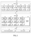
- FIG. 3 is a block diagram of a programming module according to various embodiments of the present disclosure.
- a programming module 310 may include an operating system (OS) that controls resources related to an electronic device (for example, the electronic device 101) and/or various applications executed on the OS (for example, the application programs 147).
- OS operating system
- the OS may be Android®, iOS®, Windows®, Symbian®, Tizen®, Bada®, or the like.
- the programming module 310 may include a kernel 320, middleware 330, an Application Programming Interface (API) 360, and/or applications 370. At least a part of the programming module 310 may be preloaded on the electronic device or downloaded from an external electronic device (for example, the electronic device 102 or 104, or the server 106).
- API Application Programming Interface
- the kernel 320 may include, for example, a system resource manager 321 and/or a device driver 323.
- the system resource manager 321 may control, allocate, or deallocate system resources.
- the system resource manager 321 may include at least one of a process manager, a memory manager, or a file system manager.
- the device driver 323 may include, for example, a display driver, a camera driver, a BT driver, a shared memory driver, a USB driver, a keypad driver, a WiFi driver, an audio driver, or an inter-process communication (IPC) driver.
- IPC inter-process communication
- the middleware 330 may, for example, provide a function required commonly for the applications 370 or provide various functionalities to the applications 370 through the API 360 so that the applications 370 may efficiently use limited system resources available within the electronic device.
- the middleware 330 (for example, the middleware 143) may include at least one of a runtime library 335, an application manager 341, a window manager 342, a multimedia manager 343, a resource manager 344, a power manager 345, a database manager 346, a package manager 347, a connectivity manager 348, a notification manager 349, a location manager 350, a graphic manager 351, or a security manager 352.
- the runtime library 335 may include, for example, a library module that a complier uses to add a new function in a programming language during execution of an application 370.
- the runtime library 335 may perform I/Omanagement, memory management, a function related to arithmetic function, or the like.
- the application manager 341 may manage, for example, the life cycle of at least one of the applications 370.
- the window manager 342 may manage graphical user interface (GUI) resources used for a screen.
- the multimedia manager 343 may determine formats required to play back various media files and may encode or decode a media file using a compression/decompression (CODEC) suitable for the format of the media file.
- the resource manager 344 may manage resources such as a source code of at least one of the applications 370, a memory, or storage space.
- the power manager 345 may, for example, manage a battery or a power source by operating in conjunction with a basic input/output system (BIOS) and may provide power information required for an operation of the electronic device.
- the database manager 346 may generate, search, or modify a database for at least one of the applications 370.
- the package manager 347 may manage installation or update of an application distributed as a package file.
- the connectivity manager 348 may manage, for example, wireless connectivity of WiFi, BT, or the like.
- the notification manager 349 may indicate or notify an event such as message arrival, a schedule, a proximity alarm, or the like in a manner that does not bother a user.
- the location manager 350 may mange position information about the electronic device.
- the graphic manager 351 may manage graphical effects to be provided to the user or related user interfaces.
- the security manager 352 may provide an overall security function required for system security, user authentication, or the like.
- the middleware 330 may further include a telephony manager to manage a voice or video call function of the electronic device.
- a new middleware module may be created and used by combining various functions of the above-described component modules in the middleware 330.
- the middleware 330 may provide a customized module for each OS type in order to provide differentiated functions.
- the middleware 330 may dynamically delete a part of the existing components or add a new component.
- the API 360 (for example, the API 145 shown in FIG. 1 ) is, for example, a set of API programming functions, which may be configured differently according to an OS. For example, in the case of Android or iOS, one API set may be provided per platform, whereas in the case of Tizen, two or more API sets may be provided per platform.
- the applications 370 may include, for example, one or more applications capable of providing functions such as home 371, dialer 372, short message service (SMS)/multimedia messaging service (MMS) 373, instant message (IM) 374, browser 375, camera 376, alarm 377, contacts 378, voice dial 379, e-mail 380, calendar 381, media player 382, album 383, or clock 384, health care (for example, measurement of an exercise amount or a glucose level), or providing of environment information (for example, information about atmospheric pressure, humidity, or temperature).
- SMS short message service
- MMS multimedia messaging service
- IM instant message
- the applications 370 may include an application (for the convenience of description, referred to as 'information exchange application') supporting information exchange between the electronic device (for example, the electronic device 101 shown in FIG. 1 ) and an external electronic device (the electronic device 102 or 104).
- the information exchange application may include, for example, a notification relay application for transmitting specific information to the external electronic device or a device management application for managing the external electronic device.
- the notification relay application may include a function of transmitting notification information generated from another application (for example, an SMS/MMS application, an email application, a health care application, or an environment information application) to the external electronic device (for example, the electronic device 102 or 104). Also, the notification relay application may, for example, receive notification information from the external electronic device and transmit the received notification information to a user.
- another application for example, an SMS/MMS application, an email application, a health care application, or an environment information application
- the notification relay application may, for example, receive notification information from the external electronic device and transmit the received notification information to a user.
- the device management application may, for example, manage (for example, install, delete, or update) at least a part of functions of the external electronic device (for example, the electronic device 102 or 104 shown in FIG. 1 ) communicating with the electronic device (for example, turn-on/turn-off of the external electronic device (or a part of its components) or control of the brightness (or resolution) of the display), an application executed in the external electronic device, or a service (for example, a call service or a message service) provided by the external electronic device.
- manage for example, install, delete, or update
- the external electronic device for example, the electronic device 102 or 104 shown in FIG. 1
- the electronic device for example, turn-on/turn-off of the external electronic device (or a part of its components) or control of the brightness (or resolution) of the display
- a service for example, a call service or a message service
- the applications 370 may include an application (for example, a health care application of a mobile medical equipment) designated according to a property of the external electronic device (for example, the electronic device 102 or 104).
- the applications 370 may include an application received from an external electronic device (for example, the server 106 or the electronic device 102 or 104).
- the applications 370 may include a preloaded application or a third party application downloadable from a server.
- the names of components of the programming module 310 according to the embodiment of the present disclosure may vary according to the type of an OS.
- At least a part of the programming module 310 may be implemented in software, firmware, hardware, or a combination of at least two of them. At least a part of the programming module 310 may be implemented (for example, executed) by the processor (for example, the processor 210). At least a part of the programming module 310 may include, for example, a module, a program, a routine, a set of instructions, or a process to execute one or more functions.
- At least a part of apparatuses (for example, modules or their functions) or methods (for example, operations) according to various embodiments of the present disclosure may be implemented as commands stored in a computer-readable storage medium, in the form of a programming module.
- a processor for example, the processor 120
- one or more processors may execute functions corresponding to the commands.
- the computer-readable storage medium may be, for example, the memory 130.
- FIG. 4 is a view illustrating an electronic device having a plurality of displays according to various embodiments of the present disclosure.
- the electronic device 101 may include a plurality of displays which are a first display 461 and a second display 462.
- Each of the first and second displays 461 and 462 may include a touch screen. Therefore, the electronic device 101 may receive a touch input, a gesture input, a proximity input, or a hovering input applied to at least one of the first and second displays 461 and 462 by an electronic pen or a part of a user's body.
- the first and second displays 461 and 462 may be folded or unfolded at a predetermined angle around a central shaft 430.
- a hinge or a part of a flexible display may be used to connect the first and second displays 461 and 462 with each other at the central shaft 430.
- the electronic device 101 may include at least one flexible or stretchable display.
- the at least one flexible or stretchable display included in the electronic device 101 may be modified so as to have a plurality of separate areas like a plurality of displays.
- the electronic device may sense the pressure of an input to the display 160 provided in the electronic device.
- FIG. 5 is a partial sectional view illustrating a pressure sensing structure in an electronic device according to various embodiments of the present disclosure.
- a partial structure of the electronic device 101 may include a display panel 510, a first fixing member 521, a stacked plate 531, a spacer 540, a pressure sensor 550, a printed circuit board (PCB) 533, a second fixing member 523, and a bracket 560 in this order.
- PCB printed circuit board
- the display panel 510 may be the afore-described display 160 (shown in FIG. 1 ) or touch panel 262 (shown in FIG. 2 ). Also, the display panel 510 and the touch panel 252 may be incorporated into a single module.
- the first fixing member 521 may fix the display panel 510 and the stacked plate 531 together.
- the first fixing member 521 may be a double-sided adhesive tape.
- the stacked plate 531 may be a substrate capable of providing a ground GND as an electrical reference.
- the stacked plate 531 may be a copper clad laminate.
- the spacer 540 may keep the stacked plate 531 and the pressure sensor 550 apart from each other by a predetermined gap, and change the gap between the stacked plate 531 and the pressure sensor 550 in correspondence with the pressure of an input to the display panel 510.
- the spacer 540 may be formed of silicon.
- the pressure sensor 550 may induce static charge between the pressure sensor 550 and the stacked plate 531, and sense capacitance between the pressure sensor 550 and the stacked plate 531. Further, the pressure sensor 550 may sense a variation ⁇ C of the capacitance between the pressure sensor 550 and the stacked plate 531.
- the PCB 533 may electrically interconnect components of the electronic device 101.
- the PCB 533 may be a flexible PCB (FPCB) for which a flexible insulation substrate is used.
- FPCB flexible PCB
- the second fixing member 523 may fix the PCB 533 to the bracket 560.
- the second fixing member 523 may be a double-sided adhesive tape.
- the bracket 560 may be a fixing member for fixing the afore-described components of the electronic device 101 inside the electronic device 101.
- the thickness of the spacer 540 corresponding to the gap between the stacked plate 531 and the pressure sensor 550 may be changed according to the pressure of an input to the touch panel 510.
- the pressure sensor 550 may sense a variation ⁇ C of the capacitance between the pressure sensor 550 and the stacked plate 531, caused by a change of the distance between the stacked plate 531 and the pressure sensor 550 with the space 540 in between according to the pressure of an input to the touch panel 510.
- the pressure sensor 550 may sense the pressure of the input to the touch panel 510 based on the variation ⁇ C of the capacitance.
- the processor 120 may receive information about the sensed capacitance from the pressure sensor 550, and calculate the pressure of the input to the touch panel 510 based on the capacitance variation sensed by the pressure sensor 550.
- the pressure sensor 550 may sense the pressure of a plurality of individual inputs.
- the pressure sensor 550 may sense a capacitance variation ⁇ C at each of a plurality of points, and sense the pressure of each of a plurality of inputs based on the capacitance variations ⁇ C of the plurality of points.
- the electronic device 101 may detect the position and pressure of an input.
- the electronic device 101 may detect the position of an input sensed through the touch panel 252 and detect the pressure of the input sensed through the pressure sensor 550.
- the electronic device 101 may detect the position and pressure of the input.
- the electronic device may sense the pressure of an input to a display in various manners.
- FIG. 6 is a flowchart illustrating an operation of an electronic device according to various embodiments of the present disclosure.
- the electronic device 101 receives an input to at least one of a plurality of displays included in the electronic device 101.
- the electronic device 101 may include the plurality of displays which are the first and second displays 461 and 462, and receive an input to at least one of the first and second displays 461 and 462.
- An input may be applied to a display by means of at least one touch made by an electronic pen or a user's body part.
- one or more of the first and second displays 461 and 462 may be in a turn-on state or a turn-off state.
- the electronic device 101 senses the pressure of the received input.
- the electronic device 101 may sense the pressure of an input to at least one of the plurality of displays through the pressure sensor 550 included in the electronic device 101.
- the electronic device 101 executes a first function in correspondence with the input.
- the electronic device 101 may execute the first function in correspondence with the input. For example, the electronic device 101 may enter an image adjust mode, as the first function, in order to adjust at least one of the size and position of at least one image displayed on the plurality of displays. In another example, the electronic device 101 may execute a function corresponding to the sensed pressure, as the first function. Various functions may be set as the function corresponding to the sensed pressure, as the first function. For example, as the first function, the electronic device 101 may execute a specific application, or display an image at a specific ratio on the display 160, in correspondence with the sensed pressure, which will be described below in greater detail.
- the electronic device 101 executes a second function in correspondence with the input.
- the electronic device 101 may execute the second function in correspondence with the input. For example, the electronic device 101 may execute a function corresponding to the sensed input, as the second function. Specifically, the electronic device 101 may execute a function corresponding to one or more of the position and pattern of the sensed input. Therefore, the electronic device 101 may execute a function corresponding to a general input to a display, as the second function.
- FIG. 7 is a view illustrating an input according to various embodiments of the present disclosure.
- the electronic device 101 may include the plurality of displays which are the first and second displays 461 and 462.
- the first display 461 may display a first image
- the second display 462 may display a second image.
- the first image may be an image corresponding to an SMS/MMS application 373
- the second image may be an image corresponding to a browser application 375.
- a description of the first and second images displayed on the first and second displays 461 and 462 are exemplary, and many other images may be displayed on the first and second displays 461 and 462.
- At least one of the first and second displays 461 and 462 may be in the turn-off state.
- the electronic device 101 may recognize a touch input 700 to a partial area of the first display 461.
- the pressure of the input 700 may be a first level equal to or greater than a threshold.
- the electronic device 101 may determine whether the pressure of the input 700 is equal to or greater than the predetermined threshold. If the pressure of the input 700 is equal to or greater than the threshold, the electronic device 101 may enter an image adjust mode, as the first function.
- the image adjust mode may refer to a mode in which at least one of the position and size of at least one image displayed on at least one display.
- the electronic device 101 when the electronic device 101 enters the image adjust mode, the electronic device 101 may reduce the size of an image being displayed on at least one display or shake the image as if the image were vibrating, in order to indicate that the image displayed on the at least one display is adjustable.
- the electronic device 101 may display an image unchanged on the display 160 before and after the image mode adjust mode.
- FIG. 8 is a view illustrating an electronic device placed in the image adjust mode according to various embodiments of the present disclosure.
- the electronic device 101 may display a first image layer 810 and a second image layer 820 which have been scaled down at a predetermined ratio from the first and second images displayed on the first and second displays 461 and 462, respectively. Also, the electronic device 101 may display the first and second image layers 810 and 820 on the first and second displays 461 and 462, three-dimensionally. Besides, once the electronic device 101 enters the image adjust mode, the electronic device 101 may display images on the first and second displays 461 and 462 in a different manner before and after the image adjust mode.
- the electronic device 101 may recognize an adjustment input for adjusting one or more of the position and size of at least one image displayed on at least one display 160 in the image adjust mode.
- the electronic device 101 may adjust one or more of the position and size of the at least one image displayed on the at least one display 160 in correspondence with the recognized adjustment input, and display the adjusted image.
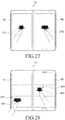
- FIGS. 9A and 9B are views illustrating image shifting according to various embodiments of the present disclosure.
- the electronic device 101 may receive a drag-and-drop input 900 that drags a partial area of the first image layer 810 displayed on the first display 461 to the right and drops the partial area of the first image layer 810. Therefore, as illustrated in FIG. 9B , the electronic device 101 may display a part 811 of the first image layer 810 on the first display 461 and the other part 813 of the first image layer 810 on the second display 462, in correspondence with the drag-and-drop input 900. The electronic device 101 may display the other part 813 of the first image layer 810, overlapped with the second image layer 820. In this manner, the electronic device 101 may adjust the position of at least one image displayed on the plurality of displays 160 in correspondence with an input in the image adjust mode.
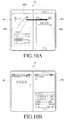
- FIGS. 10A and 10B are views illustrating image shifting according to various embodiments of the present disclosure.
- the electronic device 101 may receive a drag-and-drop input 1000 that drags an upper end area of the first image layer 810 to an upper end area of the second image layer 820 and drops the upper end area of the first image layer 810.
- the electronic device 101 may display the image corresponding to the SMS/MMS application 373 being the first image which has been displayed on the first display 461, on the second display 462, and an image corresponding to the browser application 375 being the second image which has been displayed on the second display 462, on the first display 461. In this manner, the electronic device 101 may exchange displayed images between a plurality of displays in correspondence with an input in the image adjust mode.
- FIGS. 11A and 11B are views illustrating adjustment of an image size according to various embodiments of the present disclosure.
- the electronic device 101 may receive a drag-and-drop input 1100 that drags a left boundary area of the second image layer 820 displayed on the second display 462 to the first display 461 and drops the left boundary area of the second image layer 820, as an input for adjusting the size of the image corresponding to the browser application 375 being the second image displayed on the second display 462. Therefore, as illustrated in FIG 11B , the electronic device 101 may display the image corresponding to the browser application 375 being the second image across a partial area of the first display 461 and the second display 462.
- the electronic device 101 may receive a double-tap touch input applied to a partial area of an image displayed on at least one of a plurality of displays, or a drag-and-drop input applied to the partial area to or beyond a predetermined reference, as an input for displaying an image corresponding to the input on all of the plurality of displays, in the image adjust mode.
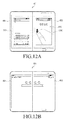
- FIGS. 12A and 12B are views illustrating adjustment of an image size according to various embodiments of the present disclosure.
- the electronic device 101 may receive a double-tap input 1200 applied to a left boundary area of the second image layer 820 displayed on the second display 462 as an input for displaying the image corresponding to the browser application 375, that is, the second image across the entire first and second displays 461 and 462.
- the electronic device 101 may display the image corresponding to the browser application 375, that is, the second image across the first and second displays 461 and 462.
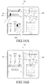
- FIGS. 13A and 13B are views illustrating adjustment of an image size according to various embodiments of the present disclosure.
- the electronic device 101 may receive a drag-and-drop input 1300 that drags a left boundary area of the second image layer 820 displayed on the second display 462 to the first display 461 and drops the left boundary area of the second image layer 820 in the image adjust mode. If the drag-and-drop input 1300 to the left boundary area of the second image layer 820 crosses a first reference line 820, the electronic device 101 may display an image corresponding to the input, that is, the second image across the entire first and second displays 461 and 462. Therefore, as illustrated in FIG. 13B , the electronic device 101 may display the image corresponding to the browser application 375, that is, the second image across the first and second displays 461 and 462. The electronic device 101 may or may not display the first reference line 1350 on the first display 461.
- the electronic device 101 may display information about a ratio, size, and the like of an image to be adjusted in correspondence with an input for adjusting an image size on a display in the image adjust mode, which will be descried below with reference to FIG. 14 .
- FIG. 14 is a view illustrating display of information about image size adjustment according to various embodiments of the present disclosure.
- the electronic device 101 may display an information window 1420 indicating a ratio of the second image to be displayed in correspondence with the input 1400. For example, if the ratio of the second image to be enlarged in correspondence with the input 1400 is 4:3, the electronic device 101 may display [4:3] in the information window 1420. Further, the electronic device 101 may display a virtual line 1430 matching the left edge of the second image to be enlarged in correspondence with the input 140. According to various embodiments of the present disclosure, the electronic device 101 may display information about at least one of the size, ratio, and the like of an image to be adjusted in correspondence with an image adjustment input in this manner.
- the electronic device 101 may receive an image adjustment input in the state where an image is displayed on the display 160 in the same manner as before the image adjust mode, adjust at least one of the size, ratio, and the like of at least one image in correspondence with the image adjustment input, and display the adjusted image on the display 160 according to various embodiments of the present disclosure.
- the electronic device 101 may execute a specific function in correspondence with the pressure of a received input according to various embodiments of the present disclosure.
- the electronic device 101 may display an image at a specific ratio or in a specific direction in correspondence with the pressure of a received input.
- the electronic device 101 may execute a specific application or a specific function in correspondence with the pressure of a received input.
- FIGS. 15A and 15B 16A and 16B , 17A and 17B , 18A and 18B , 19A and 19B , 20A and 20B , 21A and 21B , 22A and 22B , 23A and 23B , 24A and 24B , 25A and 25B ,and 26A and 26B .
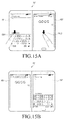
- FIGS. 15A and 15B are views illustrating display of exchanged imagesaccording to various embodiments of the present disclosure.
- the electronic device 101 may display the image corresponding to the SMS/MMS application 373 (shown in FIG. 3 ) as the first image on the first display 461, and the image corresponding to the browser application 375 (shown in FIG. 3 ) as the second image on the second display 462.
- the electronic device 101 may receive a first input 1501 being a touch on a partial area of the first display 461 and a second input 1502 being a touch on a partial area of the second display 462.
- the pressures of the first and second inputs 1501 and 1502 may be a second level equal to or greater than a threshold, or any other level.
- the electronic device 101 may exchange the plurality of images between the first and second displays 461 and 462 in correspondence with the first and second inputs 1501 and 1502 applied respectively to the first and second displays 461 and 462, and display the exchanged images on the first and second displays 461 and 462. For example, as illustrated in FIG. 15B , upon receipt of the first and second inputs 1501 and 1502, the electronic device 101 may display the first image, which has been displayed on the first display 461, on the second display 462, and the second image, which has been displayed on the second display 462, on the first display 461. According to various embodiments of the present disclosure, the electronic device 101 may exchange images between a plurality of displays and display the exchanged images on the displays, in correspondence with the pressure of an input without entering the image adjust mode.
- the electronic device 101 of the present disclosure may exchange a plurality of images displayed in different areas of the same display and display the exchanged images on the display, in correspondence with the pressures of inputs to the plurality of images. This operation will be described below with reference to FIGS. 16A and 16B .
- FIGS. 16A and 16B are views illustrating screen exchange according to various embodiments of the present disclosure.
- the electronic device 101 may display the image corresponding to the browser application 375 as a first image and an image corresponding to a weather application as a second image on the first display 461, and display an image corresponding to a map application as a third image and an image corresponding to a calendar application 381 as a fourth application on the second display 462.
- the electronic device 101 may receive a first input 1601 being a touch on a partial area corresponding to the first image in the first display 461, and a second input 1602 being a touch on another partial area corresponding to the second image in the first display 461.
- the pressures of the first and second inputs 1601 and 1602 may be the second level equal to or greater than the threshold.
- the electronic device 101 may exchange the first image and the second image displayed on the first display 461 with each other in correspondence with the first and second inputs 1601 and 1602 applied to the first display 461. For example, as illustrated in
- the electronic device 101 may display the first image, which has been displayed in an upper part of the first display 461, in a lower part of the first display 461, and the second image, which has been displayed in the lower part of the first display 461, in the upper part of the first display 461.
- the electronic device 101 may exchange the displayed positions of a plurality of images displayed on one display and display the images at the exchanged positions, in correspondence with the pressure of a received input.
- the electronic device 101 of the present disclosure may display an image corresponding to an input on all of a plurality of displays in correspondence with the pressure of the input.
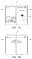
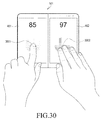
- FIGS. 17A and 17B are views illustrating full image display according to various embodiments of the present disclosure.
- the electronic device 101 may display the image corresponding to the SMS/MMS application 373 as the first image on the first display 461, and the image corresponding to the browser application 375 as the second image on the second display 462.
- the electronic device 101 may receive an input 1700 being a touch on a partial area of the second display 462.
- the pressure of the input 1700 may be a third level equal to or greater than the threshold, or any other level.
- the electronic device 101 may display the second image, which has been displayed on the second display 462, across the first and second displays 461 and 462.
- the electronic device 101 may display an image displayed on one of a plurality of displays across the plurality of displays in correspondence with the pressure of a received input without entering the image adjust mode.
- the electronic device 101 of the present disclosure may display an image in a size corresponding to the pressure of an input in a direction corresponding to the position of the input, in correspondence with the pressure and position of the input.
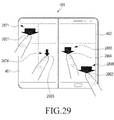
- FIGS. 18A and 18B are views illustrating adjustment of an image in correspondence with the position and pressure of an input according to various embodiments of the present disclosure.
- the electronic device 101 may display the image corresponding to the SMS/MMS application 373 (shown in FIG. 3 ) as the first image on the first display 461, and the image corresponding to the browser application 375 as the second image on the second display 462.
- the electronic device 101 may receive an input 1800 being a touch on a partial upper area of the first display 461.
- the pressure of the input 1800 may be the second level equal to or greater than the threshold, or any other level.
- the electronic device 101 may adjust at least one of the size and ratio of the first image in correspondence with the input 1800 to the first display 461.
- the electronic device 101 may display the image corresponding to the SMS/MMS application 373 as the first image in a horizontal direction in upper parts of the first and second displays 461 and 462. Also, the electronic device 101 may display the image corresponding to the browser application 375 as the second image in the horizontal direction in lower parts of the first and second displays 461 and 462.
- FIGS. 19A and 19B are views illustrating image adjustment corresponding to the position and pressure of an input according to various embodiments of the present disclosure.
- the electronic device 101 may display the image corresponding to the SMS/MMS application 373 (shown in FIG. 3 ) as the first image on the first display 461, and the image corresponding to the browser application 375 as the second image on the second display 462.
- the electronic device 101 may receive an input 1900 being a touch on a partial lower area of the first display 461.
- the pressure of the input 1900 may be the second level equal to or greater than the threshold, or any other level.
- the electronic device 101 may adjust at least one of the size and ratio of the first image in correspondence with the input 1900 to the first display 461.
- the electronic device 101 may display the image corresponding to the SMS/MMS application 373 as the first image in the horizontal direction in lower parts of the first and second displays 461 and 462. Also, the electronic device 101 may display the image corresponding to the browser application 375 as the second image in the horizontal direction in upper parts of the first and second displays 461 and 462.
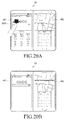
- FIGS. 20A and 20B are views illustrating image adjustment corresponding to the position and pressure of an input according to various embodiments of the present disclosure.
- the electronic device 101 may display the image corresponding to the SMS/MMS application 373 (shown in FIG. 3 ) as the first image and the image corresponding to the browser application 375 (shown in FIG. 3 ) as the second image on the first display 461, and display the image corresponding to the map application as the third image and the image corresponding to the calendar application 381 (shown in FIG. 3 ) as the fourth image on the second display 462.
- the electronic device 101 may receive an input 2000 being a touch on a partial area corresponding to the first image in the first display 461.
- the pressure of the input 2000 may be the second level equal to or greater than the threshold, or any other level.
- the electronic device 101 may adjust at least one of the size and ratio of the first image in correspondence with the input 2000 to the first display 461. For example, as illustrated in FIG. 20B , the electronic device 101 may display the first image, which has been displayed in an upper part of the first display 461, in full screen on the first display 461. In addition, the electronic device 101 may display the third and fourth images on the second display 462 in the same manner as before receiving the input 2000, or may display the second, third, and fourth images on the second display 462.
- the electronic device 101 may display an image corresponding to an input to a size corresponding to the pressure of the input in a direction corresponding to the position of the input, in correspondence with the pressure and position of the received input without entering the image adjust mode.
- the electronic device 101 according to various embodiments of the present disclosure may adjust and display an image in correspondence with the pressure and direction of an input applied to the image.
- FIGS. 21A and 21B are views illustrating image adjustment corresponding to the pressure and direction of an input according to various embodiments of the present disclosure.
- the electronic device 101 may display the image corresponding to the browser application 375 (shown in FIG. 3 ) as the first image and the image corresponding to the weather application as the second image on the first display 461, and display the image corresponding to the map application as the third image and the image corresponding to the calendar application as the fourth image on the second display 462.
- the electronic device 101 may receive an input 2100 being a downward swipe of a partial area corresponding to the first image in the first display 461.
- the pressure of the input 2100 may be the second level equal to or greater than the threshold or any other level.
- the pressure of the input 2100 may be maintained at the second level during the swipe, or may be the second level only at the start of the swipe.
- the electronic device 101 may adjust at least one of the size and ratio of the first image displayed on the first display 461 and display the adjusted image, in correspondence with the input 2100 to the first display 461. For example, as illustrated in FIG. 21B , the electronic device 101 may display the first image, which has been displayed in an upper part of the first display 461, in full screen on the first display 461. In addition, the electronic device 101 may display the third and fourth images on the second display 462 in the same manner as before receiving the input 2100, or may display the second, third, and fourth images on the second display 462.
- FIGS. 22A and 22B are views illustrating image adjustment corresponding to the pressure and direction of an input according to various embodiments of the present disclosure.
- the electronic device 101 may display the image corresponding to the browser application 375 (shown in FIG. 3 ) as the first image and the image corresponding to the weather application as the second image on the first display 461, and display the image corresponding to the map application as the third image and the image corresponding to the calendar application 381 (shown in FIG. 3 ) as the fourth image on the second display 462.
- the electronic device 101 may receive an input 2200 being a right swipe of a partial area corresponding to the first image in the first display 461.
- the pressure of the input 2200 may be the second level equal to or greater than the threshold or any other level.
- the pressure of the input 2200 may be maintained at the second level during the swipe, or may be the second level only at the start of the swipe.
- the electronic device 101 may adjust at least one of the size and ratio of the first image displayed on the first display 461 and display the adjusted image, in correspondence with the input 2200 to the first display 461. For example, as illustrated in FIG. 22B , the electronic device 101 may display the first image, which has been displayed in an upper part of the first display 461, across upper parts of the first and second displays 461 and 462. Also, the electronic device 101 may display the second image in a lower part of the first display 461, and the fourth image in a lower part of the second display 462. Or the electronic device 101 may display the second, third, and fourth images in the lower parts of the first and second displays 461 and 462.
- the electronic device 101 may execute a predetermined function in correspondence with the pressure of an input to at least one of a plurality of displays.
- FIGS. 23A and 23B are views illustrating execution of an application corresponding to the pressure of an input according to various embodiments of the present disclosure.
- the electronic device 101 may receive a first input 2301 being a touch on a partial area of the first display 461, and a second input 2302 being a touch on a partial area of the second display 462.
- the first and second displays 461 and 462 are in the turn-on or turn-off state.
- the pressure of the first input 2301 may be a fourth level and the pressure of the second input 2302 may be a fifth level.
- the pressure of each of the first and second inputs 2301 and 2302 may be equal to or greater than, or equal to or less than the threshold.
- the electronic device 101 may execute an application in correspondence with the pressures of the first and second inputs 2301 and 2302. For example, as illustrated in FIG.
- the electronic device 101 may execute the browser application 375 (shown in FIG. 3 ) being an application corresponding to the pressure of the first input 2301, that is, the fourth level and the pressure of the second input 2302, that is, the fifth level. Accordingly, the electronic device 101 may display the image corresponding to the browser application 375 (shown in FIG. 3 ) across the first and second display 461 and 462.
- FIGS. 24A and 24B are views illustrating execution of a function corresponding to the pressure of an input according to various embodiments of the present disclosure.
- the electronic device 101 may receive a first input 2401 being a touch on a partial area of the first display 461, and a second input 2402 being a touch on a partial area of the second display 462.
- the first and second displays 461 and 462 are in the turn-on or turn-off state.
- the pressure of the first input 2401 may be the fifth level and the pressure of the second input 2402 may be the fourth level.
- the pressure of each of the first and second inputs 2401 and 2402 may be equal to or greater than, or equal to or less than the threshold.
- the electronic device 101 may execute a function in correspondence with the pressures of the first and second inputs 2301 and 2302. For example, as illustrated in FIG. 24B , the electronic device 101 may switch to a silent mode as a function corresponding to the pressure of the first input 2401, that is, the fifth level and the pressure of the second input 2402, that is, the fourth level. Accordingly, the electronic device 101 may neither output a sound nor generate vibrations or a haptic effect. Also, the electronic device 101 may display an information window 2420 indicating switching to the silent mode.
- the above description of execution of a function corresponding to the pressure of an input is purely exemplary and thus should not be construed as limiting the present disclosure. Therefore, it is to be understood that the electronic device 101 according to various embodiments of the present disclosure may execute various functions corresponding to the pressure of an input according to selection of a user or a designer.
- FIGS. 25A and 25B are views illustrating screen division corresponding to the pressure of an input according to various embodiments of the present disclosure.
- the electronic device 101 may display the image corresponding to the browser application 375 (shown in FIG. 3 ) as the first image and the image corresponding to the weather application as the second image on the first display 461, and display the image corresponding to the map application as the third image and the image corresponding to the calendar application 381 (shown in FIG. 3 ) as the fourth image on the second display 462.
- the electronic device 101 may receive a first input 2501 being a touch on a partial area of the first display 461, and a second input 2502 being a touch on a partial area of the second display 462.
- the pressure of the first input 2501 may be the fourth level and the pressure of the second input 2502 may be a sixth level.
- the pressure of each of the first and second inputs 2501 and 2502 may be equal to or greater than, or equal to or less than the threshold.
- the electronic device 101 may execute a function in correspondence with the pressures of the first and second inputs 2501 and 2502. For example, as illustrated in FIG. 25B , the electronic device 101 may display a screen divided at a ratio corresponding to the pressure of the first input 2301, that is, the fourth level and the pressure of the second input 2302, that is, the sixth level on at least one of the first and second displays 461 and 462.
- the electronic device 101 may display the first image in full screen on the first display 461, and display the third image in an upper part of the second display 462 and the fourth image in a lower part of the second display 462, on a screen divided at the ratio corresponding to the pressure of the first input 2501, that is, the fourth level and the pressure of the second input 2502, that is, the sixth level.
- FIGS. 26A and 26B are views illustrating screen division corresponding to the pressure of an input according to various embodiments of the present disclosure.
- the electronic device 101 may display the image corresponding to the browser application 375 (shown in FIG. 3 ) as the first image and the image corresponding to the weather application as the second image on the first display 461, and display the image corresponding to the map application as the third image and the image corresponding to the calendar application 381 (shown in FIG. 3 ) as the fourth image on the second display 462.
- the electronic device 101 may receive a first input 2601 being a touch on a partial area of the first display 461, and a second input 2602 being a touch on a partial area of the second display 462.
- the pressure of the first input 2601 may be the fifth level and the pressure of the second input 2602 may be the fourth level.
- the pressure of each of the first and second inputs 2601 and 2602 may be equal to or greater than, or equal to or less than the threshold.
- the electronic device 101 may execute a function corresponding to the pressures of the first and second inputs 2601 and 2602. For example, as illustrated in FIG. 26B , the electronic device 101 may display a screen divided at a ratio corresponding to the pressure of the first input 2601, that is, the fifth level and the pressure of the second input 2602, that is, the fourth level on at least one of the first and second displays 461 and 462.
- the electronic device 101 may display the first image across upper parts of the first and second displays 461 and 462, with the second image in a lower part of the first display 461 and the fourth image in a lower part of the second display 462 on a screen divided at the ratio corresponding to the pressure of the first input 2601, that is, the fifth level and the pressure of the second input 2602, that is, the fourth level.
- the electronic device 101 may display a screen divided at a ratio corresponding to the pressure of a received input.
- the above description of screen division corresponding to the pressure of an input is exemplary and thus should not be construed as limiting the present disclosure. Therefore, it is to be understood that the electronic device 101 according to various embodiments of the present disclosure may display screens divided at various ratios corresponding to the pressures of inputs according to selection of a user or a designer.
- the electronic device 101 may provide a hotkey for executing a specific function corresponding to the pressure of at least one input.
- the electronic device 101 may recognize the pressure of an input to at least one display as a password pattern.
- the electronic device 101 may recognize, as a password pattern, one or more of the pressure of at least one input to at least one display and the difference between the pressures of a plurality of inputs to the at least one display.
- the electronic device 101 may recognize the pressures and positions of a plurality of inputs to at least one display as a password pattern.
- FIG. 27 is a view illustrating input of a password corresponding to the pressure of an input according to various embodiments of the present disclosure.
- the electronic device 101 may receive a first input 2701 being a touch on a partial area of the first display 461 and a second input 2702 being a touch on a partial area of the second display 462.
- the first and second displays 461 and 462 may be in the turn-on or turn-off state. If the first and second displays 461 and 462 are in the turn-on state, a lock screen or a password input screen may be displayed.
- the pressure of the first input 2701 may be the second level and the pressure of the second input 2702 may be the fourth level.
- the pressure of each of the first and second inputs 2701 and 2702 may be equal to or greater than, or equal to or less than the threshold. If the pressure of each of the first and second inputs 2701 and 2702 is equal to a predetermined pressure for a password, the electronic device 101 may determine that a required password has been received. In an embodiment, if the pressure of each of the first and second inputs 2701 and 2702 is equal to the predetermined pressure for the password, the electronic device 101 may release the displayed lock screen.
- the electronic device 101 may display a default screen on the first and second displays 461 and 462.
- the default screen may be a home screen.
- FIG. 28 is a view illustrating input of a password corresponding to the pressure of an input according to various embodiments of the present disclosure.
- each of the first and second displays 461 and 462 of the electronic device 101 may be divided into a plurality of areas. Lines that define the plurality of areas may or may not be drawn on each of the first and second displays 461 and 462.
- the electronic device 101 may receive an input to at least one of the plurality of divided areas in each of the first and second displays 461 and 462, and recognize the pressure of the input and the area corresponding to the input as a password pattern.
- the electronic device 101 may receive a first input 2801 being a touch on a fifth area 2875 among the plurality of areas of the first display 461, and a second input 2802 being a touch on a third area 2883 among the plurality of areas of the second display 462.
- the first and second displays 461 and 462 may be in the turn-on or turn-off state. If the first and second displays 461 and 462 are in the turn-on state, a lock screen or a password input screen may be displayed.
- the pressure of the first input 2801 may be the fourth level and the pressure of the second input 2802 may be the third level.
- the pressure of each of the first and second inputs 2801 and 2802 may be equal to or greater than, or equal to or less than the threshold. If the pressure and area of each of the first and second inputs 2801 and 2802 match a predetermined pressure and area for a password, the electronic device 101 may determine that a required password has been received. In an embodiment, if the pressure and area of each of the first and second inputs 2801 and 2802 match the predetermined pressure and area for the password, the electronic device 101 may release the displayed lock screen.
- the electronic device 101 may display a default screen on the first and second displays 461 and 462.
- the default screen may be a home screen.
- FIG. 29 is a view illustrating input of a password corresponding to the pressure of an input according to various embodiments of the present disclosure.
- each of the first and second displays 461 and 462 of the electronic device 101 may be divided into a plurality of areas. Lines that define the plurality of areas may or may not be drawn on each of the first and second displays 461 and 462.
- the electronic device 101 may receive a plurality of inputs to the plurality of divided areas in each of the first and second displays 461 and 462, and recognize the input order, pressures, and areas of the plurality of inputs as a password pattern.
- the electronic device 101 may receive a first input 2901 being a touch on a first area 2871 at the fourth pressure level among the plurality of areas of the first display 461, a second input 2902 being a touch on a sixth area 2886 at the fourth pressure level among the plurality of areas of the second display 462, a third input 2903 being a touch on a fourth area 2874 at the first pressure level among the plurality of areas of the first display 461, and a fourth input 2904 being a touch on a third area 2883 at the third pressure level among the plurality of areas of the second display 462.
- the first and second displays 461 and 462 may be in the turn-on or turn-off state. If the first and second displays 461 and 462 may be in the turn-on state, a lock screen or a password input screen may be displayed.
- the pressure of each of the first to fourth inputs 2901 to 2904 may be equal to or greater than, or equal to or less than the threshold. If the input order, pressures, and areas of the first to fourth inputs 2901 to 2904 match a predetermined input order, predetermined pressures, and predetermined areas for a password, the electronic device 101 may determine that a required password has been received.
- the electronic device 101 may release the displayed lock screen. In another embodiment, if the input order, pressures, and areas of the first to fourth inputs 2901 to 2904 match the predetermined input order, predetermined pressures, and predetermined areas for the password, the electronic device 101 may display a default screen on the first and second displays 461 and 462. The default screen may be a home screen.
- the electronic device 101 may receive a plurality of inputs to at least one display, and recognize the difference between the pressures of the inputs as a password pattern.
- the electronic device 101 may receive a first input applied to the first display 461 at the first pressure level, and a second input applied to the second display 462 at the third pressure level, and recognize the difference between the pressures of the first and second inputs as a password. Accordingly, if the difference between the pressures of the first and second inputs is equal to a predetermined pressure difference for a password, the electronic device 101 may determine that a required password has been received.
- a password pattern based on the pressure of an input is exemplary and thus should not be construed as limiting the present disclosure. Therefore, it is to be understood that the electronic device 101 according to various embodiments of the present disclosure may use a password pattern based on the pressure of an input in various manners according to selection of a user or a designer.
- the electronic device 101 may use one or more of the pressure of at least one input and the difference between the pressures of a plurality of inputs for a game application.
- FIG. 30 is a view illustrating a game using the pressure of an input according to various embodiments of the present disclosure.
- the electronic device 101 may receive a first input 3001 to the first display 461 and a second input 3002 to the second display 462.
- the first and second inputs 3001 and 3002 may be inputs from the same or different users.
- the electronic device 101 may display the level of the pressure of the first input 3001 on the first display 461 and the level of the pressure of the second input 3002 on the second display 462.
- the electronic device 101 may use the pressure of each of the first and second inputs 3001 and 3002 as an input to the game application.
- the electronic device 101 may use the difference between the pressures of the first and second inputs 3001 and 3002 as an input to the game application.
- the electronic device 101 when displaying content occupying a plurality of pages on the display 160, the electronic device 101 according to various embodiments of the present disclosure may turn a page based on the pressure of an input to the displayed content.
- FIG. 31 is a view illustrating page turning according to various embodiments of the present disclosure.
- the electronic device 101 may display e-book content on the first and second displays 461 and 462.
- the electronic device 101 may receive a right swipe 3100 on a partial right area of the second display 462.
- the pressure of the input 3100 may be a seventh level equal to or greater than the threshold.
- the electronic device 101 may turn the pages of the e-book content displayed on the first and second displays 461 and 462 in correspondence with the pressure of the input 3100. If the pressure of the input 3100 increases, the electronic device 101 may increase the number of pages turned during a predetermined time. If the pressure of the input 3100 decreases, the electronic device 101 may decrease the number of pages turned during a predetermined time.
- the electronic device 101 may turn pages in correspondence with the pressure of an input in various manners according to selection of a user or a designer. For example, the electronic device 101 may jump from the pages of a plurality of images displayed on the display 160 to a page in correspondence with the pressure of an input.
- an electronic device is also applicable to an electronic device equipped with a single display. Accordingly, the electronic device with a single display may sense the pressure of an input and execute a function in correspondence with the sensed pressure.
- the electronic device may sense the pressure of a pen input to a display of the electronic device, and execute a function corresponding to the sensed pressure.
- an electronic device for sensing the pressure of an input and a method for operating the electronic device can be provided.
- the electronic device according to various embodiments of the present disclosure can sense the pressure of an input as well as the position and pattern of the input, and execute a function corresponding to the sensed pressure. Further, if the sensed pressure of the input is less than a threshold, the electronic device according to various embodiments of the present disclosure can execute a function corresponding to the input. On the other hand, if the sensed pressure of the input is equal to or greater than the threshold, the electronic device according to various embodiments of the present disclosure can execute a function corresponding to the pressure of the input. Therefore, a new input pattern can be added to existing input patterns allocated to inputs. Consequently, a user can apply various inputs in combination, for various functions of the electronic device.
- Each of the components of the above-described electronic device may include one or more parts, and the name of each component may be changed according to the type of the electronic device.
- the electronic device may be configured to include at least one of the afore-described components. A part of the components may be omitted or a new component may be added to the components. Also, a part of the components of the electronic device according to various embodiments of the present disclosure may be combined into a single entity which still executes the same functions as executed by the components prior to the combining.
- the term 'module' as used herein may include its ordinary meaning including, for example, a unit of one, or a combination of two or more of hardware, software, and firmware.
- the term 'module' may be used interchangeably with terms such as, for example, unit, logic, logical block, component or circuit.
- a 'module' may be the smallest unit of an integrated part or a portion thereof.
- a 'module' may be the smallest unit for performing one or more functions, or a portion thereof.
- a 'module' may be implemented mechanically, or electronically.
- a 'module' may include at least one of a known, or to-be-developed, application-specific integrated circuit (ASIC) chip, field-programmable gate array (FPGA) or programmable logic device that perform certain operations.
- ASIC application-specific integrated circuit
- FPGA field-programmable gate array
- At least a part of apparatuses (for example, modules or their functions) or methods (for example, operations) according to various embodiments of the present disclosure may be implemented as commands stored in a computer-readable storage medium, in the form of a programming module.
- a processor for example, the processor 120
- one or more processors may execute functions corresponding to the commands.
- the computer-readable storage medium may be, for example, the memory 130.
- the computer-readable medium may include hard disk, floppy disk, magnetic media (for example, magnetic tape), optical media (for example, compact disc (CD)-ROM), DVD, magneto-optical media (for example, floptical disk), hardware devices (for example, ROM, RAM or flash memory), and the like.
- Program instructions may include machine language code that are produced by a compiler or high-level language code that may be executed by a computer using an interpreter.
- the functionalities of hardware discussed above may be implemented as one or more software modules, and vice versa in order to perform an operation according to various embodiments of the present disclosure.
- a module or a programming module according to various embodiments of the present disclosure may include one or more of the above-described components, may omit a portion thereof, or may include additional components. Operations that are performed by a module, a programming module or other components according to the present disclosure may be processed in a serial, parallel, repetitive or heuristic manner. Also, some operations may be performed in a different order or omitted, or additional operations may be added.
Applications Claiming Priority (1)
| Application Number | Priority Date | Filing Date | Title |
|---|---|---|---|
| KR1020150127830A KR102398503B1 (ko) | 2015-09-09 | 2015-09-09 | 입력의 압력을 감지하는 전자 장치 및 그 동작 방법 |
Publications (2)
| Publication Number | Publication Date |
|---|---|
| EP3141982A1 true EP3141982A1 (de) | 2017-03-15 |
| EP3141982B1 EP3141982B1 (de) | 2020-07-22 |
Family
ID=56920553
Family Applications (1)
| Application Number | Title | Priority Date | Filing Date |
|---|---|---|---|
| EP16188171.9A Active EP3141982B1 (de) | 2015-09-09 | 2016-09-09 | Elektronische vorrichtung zur messung von eingangsdruck und verfahren zum betreiben der elektronischen vorrichtung |
Country Status (4)
| Country | Link |
|---|---|
| US (1) | US10254883B2 (de) |
| EP (1) | EP3141982B1 (de) |
| KR (1) | KR102398503B1 (de) |
| CN (1) | CN107037966B (de) |
Families Citing this family (10)
| Publication number | Priority date | Publication date | Assignee | Title |
|---|---|---|---|---|
| JP6676959B2 (ja) * | 2015-12-24 | 2020-04-08 | ブラザー工業株式会社 | シンボル入力装置及びシステム |
| US20170277503A1 (en) * | 2016-03-22 | 2017-09-28 | Panasonic Automotive Systems Company Of America, Division Of Panasonic Corporation Of North America | Moving display images from one screen to another screen by hand gesturing |
| KR20180080484A (ko) * | 2017-01-04 | 2018-07-12 | 엘지전자 주식회사 | 이동 단말기 |
| KR102364420B1 (ko) * | 2017-04-26 | 2022-02-17 | 삼성전자 주식회사 | 전자 장치 및 터치 입력에 기초하여 상기 전자 장치를 제어하는 방법 |
| CN109471575A (zh) * | 2017-09-07 | 2019-03-15 | 中兴通讯股份有限公司 | 双屏移动终端的操作方法、装置及双屏移动终端 |
| KR102414477B1 (ko) * | 2017-11-23 | 2022-06-30 | 삼성전자 주식회사 | 압력 센서의 성능 저하를 방지하기 위한 탄성 부재를 포함하는 전자 장치 및 방법 |
| US11354030B2 (en) * | 2018-02-22 | 2022-06-07 | Kyocera Corporation | Electronic device, control method, and program |
| KR20220091570A (ko) * | 2019-11-06 | 2022-06-30 | 엘지전자 주식회사 | 키보드 인터페이스를 출력하는 전자 장치 및 그 제어 방법 |
| CN110989774A (zh) * | 2019-11-29 | 2020-04-10 | 维沃移动通信有限公司 | 可穿戴设备及其控制方法、控制装置 |
| US11693558B2 (en) * | 2021-06-08 | 2023-07-04 | Samsung Electronics Co., Ltd. | Method and apparatus for displaying content on display |
Citations (2)
| Publication number | Priority date | Publication date | Assignee | Title |
|---|---|---|---|---|
| WO2013169875A2 (en) * | 2012-05-09 | 2013-11-14 | Yknots Industries Llc | Device, method, and graphical user interface for displaying content associated with a corresponding affordance |
| EP2674834A2 (de) * | 2011-02-10 | 2013-12-18 | Samsung Electronics Co., Ltd. | Tragbare vorrichtung mit einer touchscreen-anzeige und steuerungsverfahren dafür |
Family Cites Families (21)
| Publication number | Priority date | Publication date | Assignee | Title |
|---|---|---|---|---|
| KR20090036191A (ko) | 2007-10-09 | 2009-04-14 | 삼성전자주식회사 | 듀얼디스플레이장치 및 이를 채용한 멀티디스플레이장치 |
| US20100050075A1 (en) * | 2008-08-22 | 2010-02-25 | Lennox Manufacturing, Inc., A Corporation Of Delaware | Display apparatus and method for a control unit for an environmental control system |
| CN101727280B (zh) * | 2009-12-25 | 2014-04-09 | 宇龙计算机通信科技(深圳)有限公司 | 一种缩放图片的方法、系统及移动终端 |
| KR20110092826A (ko) | 2010-02-10 | 2011-08-18 | 삼성전자주식회사 | 복수의 터치스크린을 구비하는 휴대 단말기의 화면 제어 방법 및 장치 |
| EP2564598A4 (de) * | 2010-04-28 | 2017-04-26 | LG Electronics Inc. | Bildanzeigevorrichtung und verfahren zu deren betrieb |
| JP5625612B2 (ja) * | 2010-08-19 | 2014-11-19 | 株式会社リコー | 操作表示装置および操作表示方法 |
| KR20120023339A (ko) * | 2010-09-03 | 2012-03-13 | 에스케이플래닛 주식회사 | 터치신호를 이용한 기능 실행 방법 및 장치 |
| KR101688942B1 (ko) * | 2010-09-03 | 2016-12-22 | 엘지전자 주식회사 | 다중 디스플레이에 기반한 사용자 인터페이스 제공 방법 및 이를 이용하는 이동 단말기 |
| US9223445B2 (en) * | 2010-12-02 | 2015-12-29 | Atmel Corporation | Position-sensing and force detection panel |
| KR101769818B1 (ko) * | 2010-12-23 | 2017-08-21 | 엘지전자 주식회사 | 휴대 단말기 및 그 동작 제어방법 |
| US9140433B2 (en) * | 2011-05-16 | 2015-09-22 | Sharp Kabushiki Kaisha | Multi display system, and display device |
| US8508494B2 (en) | 2011-06-01 | 2013-08-13 | Motorola Mobility Llc | Using pressure differences with a touch-sensitive display screen |
| CN102999099B (zh) * | 2011-09-16 | 2015-09-23 | 英业达股份有限公司 | 可携式电子装置 |
| CN103019427B (zh) * | 2011-09-28 | 2017-06-27 | 联想(北京)有限公司 | 控制方法及电子设备 |
| KR20140001265A (ko) * | 2012-06-22 | 2014-01-07 | 삼성전자주식회사 | 단말장치의 이미지 처리 장치 및 방법 |
| KR101948665B1 (ko) * | 2012-08-23 | 2019-02-18 | 삼성전자주식회사 | 플렉서블 장치 및 그 제어 방법 |
| KR102065596B1 (ko) * | 2013-02-08 | 2020-01-13 | 엘지전자 주식회사 | 사용자 인터페이스 장치 및 제어방법 |
| US9652060B2 (en) * | 2013-06-28 | 2017-05-16 | Synaptics Incorporated | Low-latency touch feedback |
| CN103473027B (zh) * | 2013-09-16 | 2017-01-04 | 张智锋 | 一种通讯终端分屏多任务交互方法及通讯终端 |
| KR102144339B1 (ko) * | 2014-02-11 | 2020-08-13 | 엘지전자 주식회사 | 전자 기기 및 전자 기기의 제어 방법 |
| CN103823592B (zh) * | 2014-02-26 | 2017-04-26 | 汕头超声显示器技术有限公司 | 一种带有力学感应功能的显示装置 |
-
2015
- 2015-09-09 KR KR1020150127830A patent/KR102398503B1/ko active IP Right Grant
-
2016
- 2016-09-01 US US15/254,204 patent/US10254883B2/en active Active
- 2016-09-09 CN CN201610812573.3A patent/CN107037966B/zh active Active
- 2016-09-09 EP EP16188171.9A patent/EP3141982B1/de active Active
Patent Citations (2)
| Publication number | Priority date | Publication date | Assignee | Title |
|---|---|---|---|---|
| EP2674834A2 (de) * | 2011-02-10 | 2013-12-18 | Samsung Electronics Co., Ltd. | Tragbare vorrichtung mit einer touchscreen-anzeige und steuerungsverfahren dafür |
| WO2013169875A2 (en) * | 2012-05-09 | 2013-11-14 | Yknots Industries Llc | Device, method, and graphical user interface for displaying content associated with a corresponding affordance |
Also Published As
| Publication number | Publication date |
|---|---|
| US10254883B2 (en) | 2019-04-09 |
| KR102398503B1 (ko) | 2022-05-17 |
| EP3141982B1 (de) | 2020-07-22 |
| KR20170030349A (ko) | 2017-03-17 |
| CN107037966A (zh) | 2017-08-11 |
| CN107037966B (zh) | 2021-10-26 |
| US20170068381A1 (en) | 2017-03-09 |
Similar Documents
| Publication | Publication Date | Title |
|---|---|---|
| US10403241B2 (en) | Electronic device and method for running function according to transformation of display of electronic device | |
| US10468903B2 (en) | Device for performing wireless charging and method thereof | |
| US11036257B2 (en) | Electronic device and method for controlling display | |
| EP3023862B1 (de) | Leistungssteuerungsverfahren und vorrichtung zur verringerung des stromverbrauchs | |
| EP3141982B1 (de) | Elektronische vorrichtung zur messung von eingangsdruck und verfahren zum betreiben der elektronischen vorrichtung | |
| KR102426070B1 (ko) | 전자 장치 및 전자 장치의 디스플레이 설정 방법 | |
| EP3118730B1 (de) | Verfahren zum betrieb einer elektronischen vorrichtung sowie elektronische vorrichtung | |
| KR102503937B1 (ko) | 전자 장치의 사용자 인터페이스 제공 방법 및 장치 | |
| US11093049B2 (en) | Electronic device and method for controlling display in electronic device | |
| KR102547115B1 (ko) | 어플리케이션을 전환하기 위한 방법 및 그 전자 장치 | |
| EP3089019B1 (de) | Verfahren zur anzeige einer benutzerschnittstelle und elektronische vorrichtung dafür | |
| KR20170116883A (ko) | 플렉서블 디바이스 및 그 동작 방법 | |
| EP3107087B1 (de) | Vorrichtung zur unabhängigen steuerung mehrerer bereiche einer anzeige und verfahren dafür | |
| US10042600B2 (en) | Method for controlling display and electronic device thereof | |
| US10719209B2 (en) | Method for outputting screen and electronic device supporting the same | |
| US10387096B2 (en) | Electronic device having multiple displays and method for operating same | |
| US20180129409A1 (en) | Method for controlling execution of application on electronic device using touchscreen and electronic device for the same | |
| KR20180014446A (ko) | 전자 장치 및 전자 장치의 터치 스크린 디스플레이 제어 방법 | |
| KR102557935B1 (ko) | 전자 장치 및 전자 장치의 디스플레이 제어 방법 | |
| US10402036B2 (en) | Electronic device and operation method thereof | |
| KR20210087417A (ko) | 디스플레이 제어 방법 및 그 전자 장치 | |
| KR20180014614A (ko) | 전자 장치 및 전자 장치의 터치 이벤트 처리 방법 | |
| KR102467434B1 (ko) | 디스플레이 밝기를 조절하는 전자 장치 및 방법 | |
| KR20170054072A (ko) | 액세서리 장치를 감지하는 전자장치 및 그의 동작 방법 | |
| KR102589496B1 (ko) | 화면 표시 방법 및 이를 지원하는 전자 장치 |
Legal Events
| Date | Code | Title | Description |
|---|---|---|---|
| PUAI | Public reference made under article 153(3) epc to a published international application that has entered the european phase |
Free format text: ORIGINAL CODE: 0009012 |
|
| STAA | Information on the status of an ep patent application or granted ep patent |
Free format text: STATUS: THE APPLICATION HAS BEEN PUBLISHED |
|
| AK | Designated contracting states |
Kind code of ref document: A1 Designated state(s): AL AT BE BG CH CY CZ DE DK EE ES FI FR GB GR HR HU IE IS IT LI LT LU LV MC MK MT NL NO PL PT RO RS SE SI SK SM TR |
|
| AX | Request for extension of the european patent |
Extension state: BA ME |
|
| STAA | Information on the status of an ep patent application or granted ep patent |
Free format text: STATUS: REQUEST FOR EXAMINATION WAS MADE |
|
| 17P | Request for examination filed |
Effective date: 20170418 |
|
| RBV | Designated contracting states (corrected) |
Designated state(s): AL AT BE BG CH CY CZ DE DK EE ES FI FR GB GR HR HU IE IS IT LI LT LU LV MC MK MT NL NO PL PT RO RS SE SI SK SM TR |
|
| RIC1 | Information provided on ipc code assigned before grant |
Ipc: G06F 1/16 20060101AFI20191219BHEP Ipc: G06F 3/0488 20130101ALI20191219BHEP |
|
| GRAP | Despatch of communication of intention to grant a patent |
Free format text: ORIGINAL CODE: EPIDOSNIGR1 |
|
| STAA | Information on the status of an ep patent application or granted ep patent |
Free format text: STATUS: GRANT OF PATENT IS INTENDED |
|
| INTG | Intention to grant announced |
Effective date: 20200217 |
|
| GRAS | Grant fee paid |
Free format text: ORIGINAL CODE: EPIDOSNIGR3 |
|
| GRAA | (expected) grant |
Free format text: ORIGINAL CODE: 0009210 |
|
| STAA | Information on the status of an ep patent application or granted ep patent |
Free format text: STATUS: THE PATENT HAS BEEN GRANTED |
|
| AK | Designated contracting states |
Kind code of ref document: B1 Designated state(s): AL AT BE BG CH CY CZ DE DK EE ES FI FR GB GR HR HU IE IS IT LI LT LU LV MC MK MT NL NO PL PT RO RS SE SI SK SM TR |
|
| REG | Reference to a national code |
Ref country code: GB Ref legal event code: FG4D |
|
| REG | Reference to a national code |
Ref country code: CH Ref legal event code: EP |
|
| REG | Reference to a national code |
Ref country code: DE Ref legal event code: R096 Ref document number: 602016040293 Country of ref document: DE |
|
| REG | Reference to a national code |
Ref country code: AT Ref legal event code: REF Ref document number: 1294004 Country of ref document: AT Kind code of ref document: T Effective date: 20200815 |
|
| REG | Reference to a national code |
Ref country code: IE Ref legal event code: FG4D |
|
| PGFP | Annual fee paid to national office [announced via postgrant information from national office to epo] |
Ref country code: GB Payment date: 20200923 Year of fee payment: 5 |
|
| REG | Reference to a national code |
Ref country code: LT Ref legal event code: MG4D |
|
| REG | Reference to a national code |
Ref country code: AT Ref legal event code: MK05 Ref document number: 1294004 Country of ref document: AT Kind code of ref document: T Effective date: 20200722 |
|
| PG25 | Lapsed in a contracting state [announced via postgrant information from national office to epo] |
Ref country code: FI Free format text: LAPSE BECAUSE OF FAILURE TO SUBMIT A TRANSLATION OF THE DESCRIPTION OR TO PAY THE FEE WITHIN THE PRESCRIBED TIME-LIMIT Effective date: 20200722 Ref country code: PT Free format text: LAPSE BECAUSE OF FAILURE TO SUBMIT A TRANSLATION OF THE DESCRIPTION OR TO PAY THE FEE WITHIN THE PRESCRIBED TIME-LIMIT Effective date: 20201123 Ref country code: HR Free format text: LAPSE BECAUSE OF FAILURE TO SUBMIT A TRANSLATION OF THE DESCRIPTION OR TO PAY THE FEE WITHIN THE PRESCRIBED TIME-LIMIT Effective date: 20200722 Ref country code: LT Free format text: LAPSE BECAUSE OF FAILURE TO SUBMIT A TRANSLATION OF THE DESCRIPTION OR TO PAY THE FEE WITHIN THE PRESCRIBED TIME-LIMIT Effective date: 20200722 Ref country code: ES Free format text: LAPSE BECAUSE OF FAILURE TO SUBMIT A TRANSLATION OF THE DESCRIPTION OR TO PAY THE FEE WITHIN THE PRESCRIBED TIME-LIMIT Effective date: 20200722 Ref country code: BG Free format text: LAPSE BECAUSE OF FAILURE TO SUBMIT A TRANSLATION OF THE DESCRIPTION OR TO PAY THE FEE WITHIN THE PRESCRIBED TIME-LIMIT Effective date: 20201022 Ref country code: SE Free format text: LAPSE BECAUSE OF FAILURE TO SUBMIT A TRANSLATION OF THE DESCRIPTION OR TO PAY THE FEE WITHIN THE PRESCRIBED TIME-LIMIT Effective date: 20200722 Ref country code: AT Free format text: LAPSE BECAUSE OF FAILURE TO SUBMIT A TRANSLATION OF THE DESCRIPTION OR TO PAY THE FEE WITHIN THE PRESCRIBED TIME-LIMIT Effective date: 20200722 Ref country code: GR Free format text: LAPSE BECAUSE OF FAILURE TO SUBMIT A TRANSLATION OF THE DESCRIPTION OR TO PAY THE FEE WITHIN THE PRESCRIBED TIME-LIMIT Effective date: 20201023 Ref country code: NO Free format text: LAPSE BECAUSE OF FAILURE TO SUBMIT A TRANSLATION OF THE DESCRIPTION OR TO PAY THE FEE WITHIN THE PRESCRIBED TIME-LIMIT Effective date: 20201022 |
|
| PG25 | Lapsed in a contracting state [announced via postgrant information from national office to epo] |
Ref country code: RS Free format text: LAPSE BECAUSE OF FAILURE TO SUBMIT A TRANSLATION OF THE DESCRIPTION OR TO PAY THE FEE WITHIN THE PRESCRIBED TIME-LIMIT Effective date: 20200722 Ref country code: LV Free format text: LAPSE BECAUSE OF FAILURE TO SUBMIT A TRANSLATION OF THE DESCRIPTION OR TO PAY THE FEE WITHIN THE PRESCRIBED TIME-LIMIT Effective date: 20200722 Ref country code: PL Free format text: LAPSE BECAUSE OF FAILURE TO SUBMIT A TRANSLATION OF THE DESCRIPTION OR TO PAY THE FEE WITHIN THE PRESCRIBED TIME-LIMIT Effective date: 20200722 Ref country code: IS Free format text: LAPSE BECAUSE OF FAILURE TO SUBMIT A TRANSLATION OF THE DESCRIPTION OR TO PAY THE FEE WITHIN THE PRESCRIBED TIME-LIMIT Effective date: 20201122 |
|
| PG25 | Lapsed in a contracting state [announced via postgrant information from national office to epo] |
Ref country code: NL Free format text: LAPSE BECAUSE OF FAILURE TO SUBMIT A TRANSLATION OF THE DESCRIPTION OR TO PAY THE FEE WITHIN THE PRESCRIBED TIME-LIMIT Effective date: 20200722 |
|
| REG | Reference to a national code |
Ref country code: DE Ref legal event code: R097 Ref document number: 602016040293 Country of ref document: DE |
|
| PG25 | Lapsed in a contracting state [announced via postgrant information from national office to epo] |
Ref country code: MC Free format text: LAPSE BECAUSE OF FAILURE TO SUBMIT A TRANSLATION OF THE DESCRIPTION OR TO PAY THE FEE WITHIN THE PRESCRIBED TIME-LIMIT Effective date: 20200722 Ref country code: RO Free format text: LAPSE BECAUSE OF FAILURE TO SUBMIT A TRANSLATION OF THE DESCRIPTION OR TO PAY THE FEE WITHIN THE PRESCRIBED TIME-LIMIT Effective date: 20200722 Ref country code: SM Free format text: LAPSE BECAUSE OF FAILURE TO SUBMIT A TRANSLATION OF THE DESCRIPTION OR TO PAY THE FEE WITHIN THE PRESCRIBED TIME-LIMIT Effective date: 20200722 Ref country code: CZ Free format text: LAPSE BECAUSE OF FAILURE TO SUBMIT A TRANSLATION OF THE DESCRIPTION OR TO PAY THE FEE WITHIN THE PRESCRIBED TIME-LIMIT Effective date: 20200722 Ref country code: DK Free format text: LAPSE BECAUSE OF FAILURE TO SUBMIT A TRANSLATION OF THE DESCRIPTION OR TO PAY THE FEE WITHIN THE PRESCRIBED TIME-LIMIT Effective date: 20200722 Ref country code: EE Free format text: LAPSE BECAUSE OF FAILURE TO SUBMIT A TRANSLATION OF THE DESCRIPTION OR TO PAY THE FEE WITHIN THE PRESCRIBED TIME-LIMIT Effective date: 20200722 Ref country code: IT Free format text: LAPSE BECAUSE OF FAILURE TO SUBMIT A TRANSLATION OF THE DESCRIPTION OR TO PAY THE FEE WITHIN THE PRESCRIBED TIME-LIMIT Effective date: 20200722 |
|
| REG | Reference to a national code |
Ref country code: CH Ref legal event code: PL |
|
| PLBE | No opposition filed within time limit |
Free format text: ORIGINAL CODE: 0009261 |
|
| STAA | Information on the status of an ep patent application or granted ep patent |
Free format text: STATUS: NO OPPOSITION FILED WITHIN TIME LIMIT |
|
| PG25 | Lapsed in a contracting state [announced via postgrant information from national office to epo] |
Ref country code: AL Free format text: LAPSE BECAUSE OF FAILURE TO SUBMIT A TRANSLATION OF THE DESCRIPTION OR TO PAY THE FEE WITHIN THE PRESCRIBED TIME-LIMIT Effective date: 20200722 |
|
| REG | Reference to a national code |
Ref country code: BE Ref legal event code: MM Effective date: 20200930 |
|
| 26N | No opposition filed |
Effective date: 20210423 |
|
| PG25 | Lapsed in a contracting state [announced via postgrant information from national office to epo] |
Ref country code: LU Free format text: LAPSE BECAUSE OF NON-PAYMENT OF DUE FEES Effective date: 20200909 Ref country code: SK Free format text: LAPSE BECAUSE OF FAILURE TO SUBMIT A TRANSLATION OF THE DESCRIPTION OR TO PAY THE FEE WITHIN THE PRESCRIBED TIME-LIMIT Effective date: 20200722 |
|
| PG25 | Lapsed in a contracting state [announced via postgrant information from national office to epo] |
Ref country code: FR Free format text: LAPSE BECAUSE OF NON-PAYMENT OF DUE FEES Effective date: 20200922 |
|
| PG25 | Lapsed in a contracting state [announced via postgrant information from national office to epo] |
Ref country code: SI Free format text: LAPSE BECAUSE OF FAILURE TO SUBMIT A TRANSLATION OF THE DESCRIPTION OR TO PAY THE FEE WITHIN THE PRESCRIBED TIME-LIMIT Effective date: 20200722 Ref country code: LI Free format text: LAPSE BECAUSE OF NON-PAYMENT OF DUE FEES Effective date: 20200930 Ref country code: IE Free format text: LAPSE BECAUSE OF NON-PAYMENT OF DUE FEES Effective date: 20200909 Ref country code: CH Free format text: LAPSE BECAUSE OF NON-PAYMENT OF DUE FEES Effective date: 20200930 Ref country code: BE Free format text: LAPSE BECAUSE OF NON-PAYMENT OF DUE FEES Effective date: 20200930 |
|
| REG | Reference to a national code |
Ref country code: NL Ref legal event code: MP Effective date: 20200722 |
|
| GBPC | Gb: european patent ceased through non-payment of renewal fee |
Effective date: 20210909 |
|
| PG25 | Lapsed in a contracting state [announced via postgrant information from national office to epo] |
Ref country code: TR Free format text: LAPSE BECAUSE OF FAILURE TO SUBMIT A TRANSLATION OF THE DESCRIPTION OR TO PAY THE FEE WITHIN THE PRESCRIBED TIME-LIMIT Effective date: 20200722 Ref country code: MT Free format text: LAPSE BECAUSE OF FAILURE TO SUBMIT A TRANSLATION OF THE DESCRIPTION OR TO PAY THE FEE WITHIN THE PRESCRIBED TIME-LIMIT Effective date: 20200722 Ref country code: CY Free format text: LAPSE BECAUSE OF FAILURE TO SUBMIT A TRANSLATION OF THE DESCRIPTION OR TO PAY THE FEE WITHIN THE PRESCRIBED TIME-LIMIT Effective date: 20200722 |
|
| PG25 | Lapsed in a contracting state [announced via postgrant information from national office to epo] |
Ref country code: MK Free format text: LAPSE BECAUSE OF FAILURE TO SUBMIT A TRANSLATION OF THE DESCRIPTION OR TO PAY THE FEE WITHIN THE PRESCRIBED TIME-LIMIT Effective date: 20200722 |
|
| PG25 | Lapsed in a contracting state [announced via postgrant information from national office to epo] |
Ref country code: GB Free format text: LAPSE BECAUSE OF NON-PAYMENT OF DUE FEES Effective date: 20210909 |
|
| PGFP | Annual fee paid to national office [announced via postgrant information from national office to epo] |
Ref country code: DE Payment date: 20230822 Year of fee payment: 8 |