EP3141740B1 - Independent power generating method using water pressure and vapor, and generating device thereof - Google Patents
Independent power generating method using water pressure and vapor, and generating device thereof Download PDFInfo
- Publication number
- EP3141740B1 EP3141740B1 EP15789436.1A EP15789436A EP3141740B1 EP 3141740 B1 EP3141740 B1 EP 3141740B1 EP 15789436 A EP15789436 A EP 15789436A EP 3141740 B1 EP3141740 B1 EP 3141740B1
- Authority
- EP
- European Patent Office
- Prior art keywords
- water
- vapor
- wheel
- tank
- condensing
- Prior art date
- Legal status (The legal status is an assumption and is not a legal conclusion. Google has not performed a legal analysis and makes no representation as to the accuracy of the status listed.)
- Active
Links
- XLYOFNOQVPJJNP-UHFFFAOYSA-N water Substances O XLYOFNOQVPJJNP-UHFFFAOYSA-N 0.000 title claims description 130
- 238000000034 method Methods 0.000 title claims description 12
- 238000010248 power generation Methods 0.000 claims description 25
- 238000010438 heat treatment Methods 0.000 claims description 15
- 238000005381 potential energy Methods 0.000 claims description 10
- 239000008400 supply water Substances 0.000 claims description 2
- 239000004020 conductor Substances 0.000 description 5
- 238000006243 chemical reaction Methods 0.000 description 3
- 238000007789 sealing Methods 0.000 description 3
- CURLTUGMZLYLDI-UHFFFAOYSA-N Carbon dioxide Chemical compound O=C=O CURLTUGMZLYLDI-UHFFFAOYSA-N 0.000 description 2
- 239000003245 coal Substances 0.000 description 2
- 238000002485 combustion reaction Methods 0.000 description 2
- 238000009833 condensation Methods 0.000 description 2
- 230000005494 condensation Effects 0.000 description 2
- 230000008878 coupling Effects 0.000 description 2
- 238000010168 coupling process Methods 0.000 description 2
- 238000005859 coupling reaction Methods 0.000 description 2
- 230000000694 effects Effects 0.000 description 2
- 230000004907 flux Effects 0.000 description 2
- 229910052770 Uranium Inorganic materials 0.000 description 1
- 229910002092 carbon dioxide Inorganic materials 0.000 description 1
- 239000001569 carbon dioxide Substances 0.000 description 1
- 239000002803 fossil fuel Substances 0.000 description 1
- 239000000446 fuel Substances 0.000 description 1
- ZZUFCTLCJUWOSV-UHFFFAOYSA-N furosemide Chemical compound C1=C(Cl)C(S(=O)(=O)N)=CC(C(O)=O)=C1NCC1=CC=CO1 ZZUFCTLCJUWOSV-UHFFFAOYSA-N 0.000 description 1
- 230000005484 gravity Effects 0.000 description 1
- 239000008236 heating water Substances 0.000 description 1
- 230000001939 inductive effect Effects 0.000 description 1
- 239000003208 petroleum Substances 0.000 description 1
- JFALSRSLKYAFGM-UHFFFAOYSA-N uranium(0) Chemical compound [U] JFALSRSLKYAFGM-UHFFFAOYSA-N 0.000 description 1
- 238000010792 warming Methods 0.000 description 1
- 239000002699 waste material Substances 0.000 description 1
Images

Classifications
-
- F—MECHANICAL ENGINEERING; LIGHTING; HEATING; WEAPONS; BLASTING
- F03—MACHINES OR ENGINES FOR LIQUIDS; WIND, SPRING, OR WEIGHT MOTORS; PRODUCING MECHANICAL POWER OR A REACTIVE PROPULSIVE THRUST, NOT OTHERWISE PROVIDED FOR
- F03B—MACHINES OR ENGINES FOR LIQUIDS
- F03B17/00—Other machines or engines
- F03B17/005—Installations wherein the liquid circulates in a closed loop ; Alleged perpetua mobilia of this or similar kind
-
- F—MECHANICAL ENGINEERING; LIGHTING; HEATING; WEAPONS; BLASTING
- F03—MACHINES OR ENGINES FOR LIQUIDS; WIND, SPRING, OR WEIGHT MOTORS; PRODUCING MECHANICAL POWER OR A REACTIVE PROPULSIVE THRUST, NOT OTHERWISE PROVIDED FOR
- F03B—MACHINES OR ENGINES FOR LIQUIDS
- F03B13/00—Adaptations of machines or engines for special use; Combinations of machines or engines with driving or driven apparatus; Power stations or aggregates
- F03B13/06—Stations or aggregates of water-storage type, e.g. comprising a turbine and a pump
-
- F—MECHANICAL ENGINEERING; LIGHTING; HEATING; WEAPONS; BLASTING
- F03—MACHINES OR ENGINES FOR LIQUIDS; WIND, SPRING, OR WEIGHT MOTORS; PRODUCING MECHANICAL POWER OR A REACTIVE PROPULSIVE THRUST, NOT OTHERWISE PROVIDED FOR
- F03B—MACHINES OR ENGINES FOR LIQUIDS
- F03B13/00—Adaptations of machines or engines for special use; Combinations of machines or engines with driving or driven apparatus; Power stations or aggregates
-
- F—MECHANICAL ENGINEERING; LIGHTING; HEATING; WEAPONS; BLASTING
- F22—STEAM GENERATION
- F22B—METHODS OF STEAM GENERATION; STEAM BOILERS
- F22B31/00—Modifications of boiler construction, or of tube systems, dependent on installation of combustion apparatus; Arrangements of dispositions of combustion apparatus
-
- F—MECHANICAL ENGINEERING; LIGHTING; HEATING; WEAPONS; BLASTING
- F22—STEAM GENERATION
- F22B—METHODS OF STEAM GENERATION; STEAM BOILERS
- F22B33/00—Steam-generation plants, e.g. comprising steam boilers of different types in mutual association
- F22B33/18—Combinations of steam boilers with other apparatus
-
- H—ELECTRICITY
- H02—GENERATION; CONVERSION OR DISTRIBUTION OF ELECTRIC POWER
- H02K—DYNAMO-ELECTRIC MACHINES
- H02K7/00—Arrangements for handling mechanical energy structurally associated with dynamo-electric machines, e.g. structural association with mechanical driving motors or auxiliary dynamo-electric machines
- H02K7/18—Structural association of electric generators with mechanical driving motors, e.g. with turbines
- H02K7/1807—Rotary generators
- H02K7/1823—Rotary generators structurally associated with turbines or similar engines
-
- F—MECHANICAL ENGINEERING; LIGHTING; HEATING; WEAPONS; BLASTING
- F05—INDEXING SCHEMES RELATING TO ENGINES OR PUMPS IN VARIOUS SUBCLASSES OF CLASSES F01-F04
- F05B—INDEXING SCHEME RELATING TO WIND, SPRING, WEIGHT, INERTIA OR LIKE MOTORS, TO MACHINES OR ENGINES FOR LIQUIDS COVERED BY SUBCLASSES F03B, F03D AND F03G
- F05B2220/00—Application
- F05B2220/70—Application in combination with
- F05B2220/702—Application in combination with the other apparatus being a steam turbine
-
- Y—GENERAL TAGGING OF NEW TECHNOLOGICAL DEVELOPMENTS; GENERAL TAGGING OF CROSS-SECTIONAL TECHNOLOGIES SPANNING OVER SEVERAL SECTIONS OF THE IPC; TECHNICAL SUBJECTS COVERED BY FORMER USPC CROSS-REFERENCE ART COLLECTIONS [XRACs] AND DIGESTS
- Y02—TECHNOLOGIES OR APPLICATIONS FOR MITIGATION OR ADAPTATION AGAINST CLIMATE CHANGE
- Y02E—REDUCTION OF GREENHOUSE GAS [GHG] EMISSIONS, RELATED TO ENERGY GENERATION, TRANSMISSION OR DISTRIBUTION
- Y02E10/00—Energy generation through renewable energy sources
- Y02E10/20—Hydro energy
-
- Y—GENERAL TAGGING OF NEW TECHNOLOGICAL DEVELOPMENTS; GENERAL TAGGING OF CROSS-SECTIONAL TECHNOLOGIES SPANNING OVER SEVERAL SECTIONS OF THE IPC; TECHNICAL SUBJECTS COVERED BY FORMER USPC CROSS-REFERENCE ART COLLECTIONS [XRACs] AND DIGESTS
- Y02—TECHNOLOGIES OR APPLICATIONS FOR MITIGATION OR ADAPTATION AGAINST CLIMATE CHANGE
- Y02E—REDUCTION OF GREENHOUSE GAS [GHG] EMISSIONS, RELATED TO ENERGY GENERATION, TRANSMISSION OR DISTRIBUTION
- Y02E60/00—Enabling technologies; Technologies with a potential or indirect contribution to GHG emissions mitigation
- Y02E60/16—Mechanical energy storage, e.g. flywheels or pressurised fluids
-
- Y—GENERAL TAGGING OF NEW TECHNOLOGICAL DEVELOPMENTS; GENERAL TAGGING OF CROSS-SECTIONAL TECHNOLOGIES SPANNING OVER SEVERAL SECTIONS OF THE IPC; TECHNICAL SUBJECTS COVERED BY FORMER USPC CROSS-REFERENCE ART COLLECTIONS [XRACs] AND DIGESTS
- Y02—TECHNOLOGIES OR APPLICATIONS FOR MITIGATION OR ADAPTATION AGAINST CLIMATE CHANGE
- Y02P—CLIMATE CHANGE MITIGATION TECHNOLOGIES IN THE PRODUCTION OR PROCESSING OF GOODS
- Y02P80/00—Climate change mitigation technologies for sector-wide applications
- Y02P80/10—Efficient use of energy, e.g. using compressed air or pressurized fluid as energy carrier
- Y02P80/15—On-site combined power, heat or cool generation or distribution, e.g. combined heat and power [CHP] supply
-
- Y—GENERAL TAGGING OF NEW TECHNOLOGICAL DEVELOPMENTS; GENERAL TAGGING OF CROSS-SECTIONAL TECHNOLOGIES SPANNING OVER SEVERAL SECTIONS OF THE IPC; TECHNICAL SUBJECTS COVERED BY FORMER USPC CROSS-REFERENCE ART COLLECTIONS [XRACs] AND DIGESTS
- Y02—TECHNOLOGIES OR APPLICATIONS FOR MITIGATION OR ADAPTATION AGAINST CLIMATE CHANGE
- Y02P—CLIMATE CHANGE MITIGATION TECHNOLOGIES IN THE PRODUCTION OR PROCESSING OF GOODS
- Y02P90/00—Enabling technologies with a potential contribution to greenhouse gas [GHG] emissions mitigation
- Y02P90/50—Energy storage in industry with an added climate change mitigation effect
Definitions
- the present invention relates to an independent power generating method using water pressure and vapor, a generating device thereof, and more particularly, to an independent power generating method and a generating device thereof, which enables an electric generator to perform power generation by rotating a water wheel using water pressure and vapor, to thereby produce electric power (see for example DE 4035870 A1 ).
- an electric generator serves to convert mechanical energy transferred from an external power source into electrical energy
- an example of the external power source may include a turbine, a water wheel, an electric motor, an engine, etc.
- a method of generating electrical energy using this external power source may be performed by hydroelectric power generation using potential energy difference of water, power generation directly using a natural force such as wind-power generation using a wind force, and artificial power generation such as thermal power generation and nuclear power generation using a natural source including petroleum, coal, or uranium.
- such a generating principle of the electric generator using the external power source is based on a relative relationship between a magnetic force and electrons in a conductor.
- a voltage is induced between opposite ends of the conductor, and a current flows by the induced voltage.
- a magnitude of the induced voltage E is related to a magnetic flux density B, a length I of the conductor in the magnetic field, and a movement speed V of the conductor. Accordingly, external power is required for a power-generating operation of the electric generator, and it is necessary to continuously supply mechanical energy from the external power source.
- Patent Application Publication No. 2012-86004 was disclosed as one of the conventional arts.
- the present invention are directed to provide an independent power generating method and a generating device thereof using water pressure and vapor, having advantages of being capable of producing power by power generation of an electric generator by efficiently rotating a water wheel connected with the electric generator through circulation of water that can be continuously used as an external power source of the electric generator.
- An exemplary embodiment of the present invention provides an independent power generating device as recited in claim 1 and an independent power generating method as recited in claim 2.
- the independent power generating method and the generating device thereof thereby having an effect of producing power by effectively rotating the water wheel connected with the electric generator through water circulation.
- the first water wheel is rotated by water pressure depending on potential energy of the flowing water, and thus first power is generated by the electric generator connected with a rotating shaft of the first water wheel;
- the water that completes first power generation is heated in the heating boiler to generate high-pressure vapor which rotates the vapor wheel, and thus-generated torque is applied to the electric generator connected with the rotating shaft of the vapor wheel to generate second power;
- the vapor that completes second power generation is exhausted into the condensing tank, condensate water obtained by condensing the vapor is allowed to vertically downwardly flow, thus-generated torque is applied to the electric generator connected with the rotating shaft of the second water wheel to generate third power;
- the water that completes third power generation is allowed to flow in the water tank to perform a continuous power generation circulating operation.
- an independent power generating device using water pressure and vapor is configured to include a water tank 110 disposed at a predetermined height so as to have potential energy; a first water wheel 120 disposed at an exhaust side of the water tank 110 to vertically face the water tank 110 and to rotate by head drop of water, an electric generator 121 being coupled to a rotating shaft thereof; a heating boiler 130 disposed to communicate with a lower portion of the first water wheel 120 to generate vapor by heating inlet water; a vapor wheel 140 disposed to rotate by high-pressure vapor ejected by communicating with a vapor exhausting end of the heating boiler 130, an electric generator 141 being coupled to a rotating shaft thereof; a condensing tank 150 mounted at an upper side of the vapor wheel 140 to have a first side communicating with the vapor wheel 140 so as to condense vapor and to allow condensate water to flow toward a second side to exhaust it; and a second water wheel 160 disposed to downwardly communicate with an exhaust side of the conden
- the water tank 110 is mounted at a predetermined height to store a predetermined amount of water, and is disposed at a lower side of the second water wheel 160 to continuously receive water from the second water wheel 160. Further, a control valve 111 is coupled to the water tank 110 at a lower side thereof to supply the stored water to the lower side at a predetermined supply rate.
- the first water wheel 120 is mounted at the lower side of the water tank 110 to communicate with each other to rotate by potential energy of the water that is downwardly supplied from the water tank 110 and to couple the electric generator 121 to the rotating shaft thereof so as to generate power by a toque of the first water wheel 120.
- a casing may be disposed to surround the first water wheel 120 while closing and sealing an external surface of the first water wheel 120.
- the heating boiler 130 includes a vapor generator 131 which communicates with the first water wheel 120 to rotate the first water wheel 120, and then receives and heats the water that drops to the lower side to generate high-pressure vapor and ejects it through an exhaust pipe that communicates with the vapor wheel 140.
- the heating boiler 130 may be formed at a side of the first water wheel 120 to be lower than the first water wheel 120 such that the exhaust pipe is slantly formed to naturally receive water from the first water wheel 120.
- the vapor wheel 140 communicates with the vapor generator 131 of the heating boiler 130 to rotate by receiving the high-pressure vapor ejected through the exhaust pipe and couples the electric generator 141 to the rotating shaft thereof so as to produce power.
- a casing may be disposed to surround the vapor wheel 140 which closing and sealing an external surface thereof, and a typical nozzle and the like may be disposed at an ejection end of the exhaust pipe to exhaust the high-pressure vapor.
- the vapor wheel 140 upwardly communicates with a first side of the condensing tank 150 to exhaust the vapor that is used for rotating the vapor wheel 140.
- the condensing tank 150 communicates with an upper side of the vapor wheel 140 at a first side thereof such that a check valve 152 is formed in the connection pipe to facilitate introduction of the vapor that comes up after the vapor wheel 140 is rotated, into the condensing tank 150 and to prevent the vapor introduced into the condensing tank 150 from flowing backward.
- the vapor introduced into the condensing tank 150 is condensed to flow therein toward a second side thereof so as to downwardly supply water at a predetermined supply rate by allowing a lower portion of a second side of the condensing tank 150 to communicate with an upper portion of the second water wheel 160 with a connection pipe and coupling a control valve 151 to the connection pipe.
- a typical condensing fan, condensing piece, or condensing net for inducing easy condensation of the vapor may be provided in various complex ways in the condensing tank 150.
- the second water wheel 160 communicates with the lower portion of the second side of the condensing tank 150 to rotate by potential energy of the condensate supplied from the condensing tank 150, and generates power by coupling the electric generator 161 to the rotating shaft of the second water wheel 160.
- a casing may be disposed to surround the second water wheel 160 while closing and sealing an external surface of the second water wheel 160.
- the water tank 110 is disposed at a lower side of the second water wheel 160 to communicate with the second water wheel 160 to supply the water that downwardly drops after the second water wheel 160 is rotated, to the water tank 110.
- the independent power generating method using water pressure and vapor includes a first power generating operation includes, when water is filled in the water tank 110 and a predetermined amount of water is allowed to vertically downwardly flow, water pressure depending on potential energy of the flowing water is applied to the first water wheel 120 to rotate the first water wheel 120, and thus-generated toque is applied to the electric generator 121 connected with a rotating shaft of the first water wheel 120 to generate first power; a high-pressure vapor supplying operation in which water that completes first power generation in the first power generating operation is allowed to flow in the heating boiler 130, the water introduced into the heating boiler 130 is heated to generate high-pressure vapor by using the vapor generator 131 and to supply it to the vapor wheel 140; a second power generating operation in which a pressure of the vapor ejected in the high-pressure vapor supplying operation is applied to the vapor wheel 140 to rotate the vapor wheel 140, and thus-generated torque is applied to the electric generator 141 connected with a rotating shaft of the vapor wheel 140 to generate second power;
- the independent power generating device 100 may be installed in an external wall of a factory or a building, and the condensing tank may be largely formed in a rooftop thereof to perform sufficient condensation.
- water resource is hardly dissipated since power is generated by using natural head drop of water caused by water gravity and vapor and the vapor is re-used by naturally arising and condensing it.
Description
- The present invention relates to an independent power generating method using water pressure and vapor, a generating device thereof, and more particularly, to an independent power generating method and a generating device thereof, which enables an electric generator to perform power generation by rotating a water wheel using water pressure and vapor, to thereby produce electric power (see for example
DE 4035870 A1 ). - In general, an electric generator serves to convert mechanical energy transferred from an external power source into electrical energy, and an example of the external power source may include a turbine, a water wheel, an electric motor, an engine, etc.
- A method of generating electrical energy using this external power source may be performed by hydroelectric power generation using potential energy difference of water, power generation directly using a natural force such as wind-power generation using a wind force, and artificial power generation such as thermal power generation and nuclear power generation using a natural source including petroleum, coal, or uranium.
- As well known, such a generating principle of the electric generator using the external power source is based on a relative relationship between a magnetic force and electrons in a conductor. When magnetic flux is disconnected by the conductor, a voltage is induced between opposite ends of the conductor, and a current flows by the induced voltage. In this case, a magnitude of the induced voltage E is related to a magnetic flux density B, a length I of the conductor in the magnetic field, and a movement speed V of the conductor. Accordingly, external power is required for a power-generating operation of the electric generator, and it is necessary to continuously supply mechanical energy from the external power source.
- However, in the case of the thermal power generation or the nuclear power generation, an electric generator is driven by using thermal energy generated by combustion or a nuclear reaction of a natural resource. Accordingly, a conversion efficiency into electrical energy is deteriorated due to a loss of thermal energy and many environment-related problems associated with the development such as global warming caused by carbon dioxide generated by fuel combustion and reflective power leakage of nuclear reactions or processing problems of nuclear waste have emerged.
- In addition, among typical fossil fuel, reserves of a natural resource such as coal or oil have a specific limit, and thus its available energy is expected to be depleted, which causes a high-price trend in which oil price continuously increases. As a result, serious problems that a new alternative energy needs to be developed has been raised, and the use of natural energy using hydro, wind or solar power, etc. is restricted in relation to the environment.
- A Patent Application Publication No.
2012-86004 - The present invention are directed to provide an independent power generating method and a generating device thereof using water pressure and vapor, having advantages of being capable of producing power by power generation of an electric generator by efficiently rotating a water wheel connected with the electric generator through circulation of water that can be continuously used as an external power source of the electric generator.
- An exemplary embodiment of the present invention provides an independent power generating device as recited in claim 1 and an independent power generating method as recited in claim 2.
- Accordingly, the independent power generating method and the generating device thereof the present invention, thereby having an effect of producing power by effectively rotating the water wheel connected with the electric generator through water circulation. Specifically, when an amount of water is allowed to vertically downwardly flow from the water tank, the first water wheel is rotated by water pressure depending on potential energy of the flowing water, and thus first power is generated by the electric generator connected with a rotating shaft of the first water wheel; the water that completes first power generation is heated in the heating boiler to generate high-pressure vapor which rotates the vapor wheel, and thus-generated torque is applied to the electric generator connected with the rotating shaft of the vapor wheel to generate second power; the vapor that completes second power generation is exhausted into the condensing tank, condensate water obtained by condensing the vapor is allowed to vertically downwardly flow, thus-generated torque is applied to the electric generator connected with the rotating shaft of the second water wheel to generate third power; and the water that completes third power generation is allowed to flow in the water tank to perform a continuous power generation circulating operation.
-
-
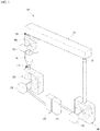
FIG. 1 is a perspective view illustrating an independent power generating method and a generating device thereof using water pressure and vapor according to the present invention. -
FIG. 2 is a front view illustrating an independent power generating method and a generating device thereof using water pressure and vapor according to the present invention. - Hereinafter, an exemplary embodiment of the present invention will be described with reference to the accompanying drawings.
- As shown in
FIGS. 1 to 2 , an independent power generating device using water pressure and vapor is configured to include awater tank 110 disposed at a predetermined height so as to have potential energy; afirst water wheel 120 disposed at an exhaust side of thewater tank 110 to vertically face thewater tank 110 and to rotate by head drop of water, anelectric generator 121 being coupled to a rotating shaft thereof; aheating boiler 130 disposed to communicate with a lower portion of thefirst water wheel 120 to generate vapor by heating inlet water; avapor wheel 140 disposed to rotate by high-pressure vapor ejected by communicating with a vapor exhausting end of theheating boiler 130, anelectric generator 141 being coupled to a rotating shaft thereof; acondensing tank 150 mounted at an upper side of thevapor wheel 140 to have a first side communicating with thevapor wheel 140 so as to condense vapor and to allow condensate water to flow toward a second side to exhaust it; and asecond water wheel 160 disposed to downwardly communicate with an exhaust side of thecondensing tank 150, to rotate by head drop of the condensate water, theelectric generator 121 being coupled to a rotating shaft, and to downwardly communicate with thewater tank 110. - The
water tank 110 is mounted at a predetermined height to store a predetermined amount of water, and is disposed at a lower side of thesecond water wheel 160 to continuously receive water from thesecond water wheel 160. Further, acontrol valve 111 is coupled to thewater tank 110 at a lower side thereof to supply the stored water to the lower side at a predetermined supply rate. - The
first water wheel 120 is mounted at the lower side of thewater tank 110 to communicate with each other to rotate by potential energy of the water that is downwardly supplied from thewater tank 110 and to couple theelectric generator 121 to the rotating shaft thereof so as to generate power by a toque of thefirst water wheel 120. - Herein, a casing may be disposed to surround the
first water wheel 120 while closing and sealing an external surface of thefirst water wheel 120. - The
heating boiler 130 includes avapor generator 131 which communicates with thefirst water wheel 120 to rotate thefirst water wheel 120, and then receives and heats the water that drops to the lower side to generate high-pressure vapor and ejects it through an exhaust pipe that communicates with thevapor wheel 140. - Further, the
heating boiler 130 may be formed at a side of thefirst water wheel 120 to be lower than thefirst water wheel 120 such that the exhaust pipe is slantly formed to naturally receive water from thefirst water wheel 120. - The
vapor wheel 140 communicates with thevapor generator 131 of theheating boiler 130 to rotate by receiving the high-pressure vapor ejected through the exhaust pipe and couples theelectric generator 141 to the rotating shaft thereof so as to produce power. - Herein, a casing may be disposed to surround the
vapor wheel 140 which closing and sealing an external surface thereof, and a typical nozzle and the like may be disposed at an ejection end of the exhaust pipe to exhaust the high-pressure vapor. - In addition, the
vapor wheel 140 upwardly communicates with a first side of thecondensing tank 150 to exhaust the vapor that is used for rotating thevapor wheel 140. - The
condensing tank 150 communicates with an upper side of thevapor wheel 140 at a first side thereof such that acheck valve 152 is formed in the connection pipe to facilitate introduction of the vapor that comes up after thevapor wheel 140 is rotated, into thecondensing tank 150 and to prevent the vapor introduced into thecondensing tank 150 from flowing backward. - Furthermore, the vapor introduced into the
condensing tank 150 is condensed to flow therein toward a second side thereof so as to downwardly supply water at a predetermined supply rate by allowing a lower portion of a second side of thecondensing tank 150 to communicate with an upper portion of thesecond water wheel 160 with a connection pipe and coupling acontrol valve 151 to the connection pipe. - In addition, a typical condensing fan, condensing piece, or condensing net for inducing easy condensation of the vapor may be provided in various complex ways in the
condensing tank 150. - The
second water wheel 160 communicates with the lower portion of the second side of thecondensing tank 150 to rotate by potential energy of the condensate supplied from thecondensing tank 150, and generates power by coupling theelectric generator 161 to the rotating shaft of thesecond water wheel 160. - Herein, a casing may be disposed to surround the
second water wheel 160 while closing and sealing an external surface of thesecond water wheel 160. - Further, the
water tank 110 is disposed at a lower side of thesecond water wheel 160 to communicate with thesecond water wheel 160 to supply the water that downwardly drops after thesecond water wheel 160 is rotated, to thewater tank 110. - Hereinafter, an independent power generating method using water pressure and vapor according to the present invention will be described.
- The independent power generating method using water pressure and vapor includes a first power generating operation includes, when water is filled in the
water tank 110 and a predetermined amount of water is allowed to vertically downwardly flow, water pressure depending on potential energy of the flowing water is applied to thefirst water wheel 120 to rotate thefirst water wheel 120, and thus-generated toque is applied to theelectric generator 121 connected with a rotating shaft of thefirst water wheel 120 to generate first power; a high-pressure vapor supplying operation in which water that completes first power generation in the first power generating operation is allowed to flow in theheating boiler 130, the water introduced into theheating boiler 130 is heated to generate high-pressure vapor by using thevapor generator 131 and to supply it to thevapor wheel 140; a second power generating operation in which a pressure of the vapor ejected in the high-pressure vapor supplying operation is applied to thevapor wheel 140 to rotate thevapor wheel 140, and thus-generated torque is applied to theelectric generator 141 connected with a rotating shaft of thevapor wheel 140 to generate second power; a vapor condensing operation in which water that completes second power generation in the second power generating operation is exhausted to thecondensing tank 150, and the vapor introduced into thecondensing tank 150 is condensed; a third power generating operation in which condensate water obtained by condensing the vapor in the vapor condensing operation is allowed to vertically downwardly flow, water pressure depending on potential energy of the flowing water is applied to thesecond water wheel 160 to rotate thesecond water wheel 160, and thus-generated toque is applied to theelectric generator 161 connected with a rotating shaft of thesecond water wheel 160 to generate the third power; and the third power generation circulating operation in which water that completes third power generation in the third power generating operation is allowed to flow in thewater tank 110 to perform a continuous power generation circulating operation on the water. - Meanwhile, the independent
power generating device 100 according to the present invention may be installed in an external wall of a factory or a building, and the condensing tank may be largely formed in a rooftop thereof to perform sufficient condensation. - Furthermore, in which power is continuously generated by sequentially circulating water through water head drop and high-pressure vapor, it is possible to continuously perform independent power generation by using minimum energy obtained by heating water in the
heating boiler 130 to generate vapor - Particularly, water resource is hardly dissipated since power is generated by using natural head drop of water caused by water gravity and vapor and the vapor is re-used by naturally arising and condensing it.
Claims (2)
- An independent power generating device using water pressure and vapor, comprising:a water tank (110) disposed at a predetermined height to have potential energy;a first water wheel (120) disposed at an exhaust side of the water tank (110) to vertically face the water tank (110) and to rotate by head drop of water, an electric generator (121) being coupled to a rotating shaft of the first water wheel (120);a heating boiler (130) disposed to communicate with a lower portion of the first water wheel (120) to generate vapor by heating inlet water;a vapor wheel (140) disposed to rotate by high-pressure vapor ejected by communicating with a vapor exhausting end of the heating boiler (130), an electric generator (141) being coupled to a rotating shaft of the vapor wheel (140);a condensing tank (150) mounted at an upper side of the vapor wheel (140) to have a first side communicating with the vapor wheel (140) so as to condense vapor and to allow condensate water to flow toward an another side to exhaust it; anda second water wheel (160) disposed to downwardly communicate with an exhaust side of the condensing tank (150), to rotate by head drop of the condensate, an electric generator (161) being coupled to a rotating shaft of the second water wheel (160), and to downwardly communicate with the water tank (110);wherein a check valve (152) is formed in the connection pipe to facilitate introduction of the vapor that comes up after the vapor wheel (140) is rotated, into the condensing tank (150) and to prevent the vapor introduced into the condensing tank (150) from flowing backward, andwherein a portion of a second side of the condensing tank (150) communicates with an upper portion of the second water wheel (160) with the connection pipe and a control valve (151) is coupled to the connection pipe to downwardly supply water at a predetermined supply rate.
- An independent power generating method using water pressure and vapor, comprising:a first power generating operation in which, when water is filled in a water tank (110) and a predetermined amount of water is allowed to vertically downwardly flow, water pressure depending on potential energy of the flowing water is applied to a first water wheel (120) to rotate the first water wheel (120), and thus-generated toque is applied to an electric generator (121) connected with a rotating shaft of the first water wheel (120) to generate first power;a high-pressure vapor supplying operation in which water that completes first power generation in the first power generating operation is allowed to flow in a heating boiler (130), the water introduced into the heating boiler (130) is heated to generate high-pressure vapor by using a vapor generator (131) and to supply it to a vapor wheel (140);a second power generating operation in which a pressure of the vapor ejected in the high-pressure vapor supplying operation is applied to the vapor wheel (140) to rotate the vapor wheel (140), and thus-generated torque is applied to an electric generator (141) connected with a rotating shaft of the vapor wheel (140) to generate second power;a vapor condensing operation in which water that completes second power generation in the second power generating operation is exhausted to a condensing tank (150), and the vapor introduced into the condensing tank (150) is condensed;a third power generating operation in which condensate water obtained by condensing the vapor in the vapor condensing operation is allowed to vertically downwardly flow, water pressure depending on potential energy of the flowing water is applied to a second water wheel (160) to rotate the second water wheel (160), and thus-generated toque is applied to an electric generator (161) connected with a rotating shaft of the second water wheel (160) to generate third power; anda power generation circulating operation in which water that completes third power generation in the third power generating operation is allowed to flow in the water tank (110) to perform a continuous power generation circulating operation on the water;wherein in the vapor condensing operation a check valve (152) is controlled to prevent the vapor introduced into the condensing tank (150) from flowing backward.
Applications Claiming Priority (2)
| Application Number | Priority Date | Filing Date | Title |
|---|---|---|---|
| KR20140054272A KR101495566B1 (en) | 2014-05-07 | 2014-05-07 | Independent electric power method and device using steam and liquid pressure |
| PCT/KR2015/003359 WO2015170830A1 (en) | 2014-05-07 | 2015-04-03 | Independent power generating method using water pressure and vapor, and generating device thereof |
Publications (3)
| Publication Number | Publication Date |
|---|---|
| EP3141740A1 EP3141740A1 (en) | 2017-03-15 |
| EP3141740A4 EP3141740A4 (en) | 2018-01-10 |
| EP3141740B1 true EP3141740B1 (en) | 2019-06-12 |
Family
ID=52594342
Family Applications (1)
| Application Number | Title | Priority Date | Filing Date |
|---|---|---|---|
| EP15789436.1A Active EP3141740B1 (en) | 2014-05-07 | 2015-04-03 | Independent power generating method using water pressure and vapor, and generating device thereof |
Country Status (6)
| Country | Link |
|---|---|
| US (1) | US10247167B2 (en) |
| EP (1) | EP3141740B1 (en) |
| JP (1) | JP6622288B2 (en) |
| KR (1) | KR101495566B1 (en) |
| CN (1) | CN106460774A (en) |
| WO (1) | WO2015170830A1 (en) |
Families Citing this family (6)
| Publication number | Priority date | Publication date | Assignee | Title |
|---|---|---|---|---|
| KR101495566B1 (en) | 2014-05-07 | 2015-02-25 | 허상채 | Independent electric power method and device using steam and liquid pressure |
| DE202016106400U1 (en) * | 2016-11-15 | 2017-01-30 | Markus Fürstenberg | Energy-storing, hydraulic device |
| KR101945929B1 (en) * | 2017-07-03 | 2019-02-08 | 진동열 | Buoyancy power generation system using waste heat |
| CN111356836A (en) * | 2017-11-07 | 2020-06-30 | 崔祉年 | High-pressure water-spraying electric power generation system |
| CN110739882B (en) * | 2019-09-27 | 2022-12-02 | 上海电力大学 | Jet flow power generation device and method based on semiconductor temperature difference power generation |
| CN112459856B (en) * | 2019-11-29 | 2024-02-27 | 钟学斌 | Prime mover, acting method and water turbine set |
Family Cites Families (49)
| Publication number | Priority date | Publication date | Assignee | Title |
|---|---|---|---|---|
| US4116005A (en) * | 1977-06-06 | 1978-09-26 | General Electric Company | Combined cycle power plant with atmospheric fluidized bed combustor |
| US4306416A (en) * | 1979-05-15 | 1981-12-22 | Joseph Iozzi | Closed cycle, hydraulic-turbine heat engine |
| US4739620A (en) * | 1980-09-04 | 1988-04-26 | Pierce John E | Solar energy power system |
| US4341490A (en) * | 1980-10-15 | 1982-07-27 | Keeling Walter W | Self-sustaining land irrigating and hydroelectric power generating system |
| US4408960A (en) * | 1981-09-11 | 1983-10-11 | Logic Devices, Inc. | Pneumatic method and apparatus for circulating liquids |
| BE891942A (en) * | 1982-01-29 | 1982-05-17 | Ceulemans Andre E S | DRIVE BY EVAPORATION AND CONDENSATION |
| US4443707A (en) * | 1982-11-19 | 1984-04-17 | Frank Scieri | Hydro electric generating system |
| US4627241A (en) * | 1983-08-04 | 1986-12-09 | Johnston Barry W | Closed loop solar collector system powering a self-starting uniflow steam engine |
| US4698973A (en) * | 1983-08-04 | 1987-10-13 | Johnston Barry W | Closed loop solar collector system powering a self-starting uniflow engine |
| EP0199902A1 (en) * | 1985-04-29 | 1986-11-05 | GebràDer Sulzer Aktiengesellschaft | Combined hot air and steam plant |
| US4805410A (en) * | 1988-01-28 | 1989-02-21 | Barry Johnston | Closed loop recirculation system for a working fluid with regeneration |
| DE4035870A1 (en) * | 1990-11-12 | 1992-05-14 | Priebe Klaus Peter | Work process and equipment - uses thermal energy from heat sources evaporating easily boiled medium in heat exchanger |
| JPH05256108A (en) * | 1992-03-12 | 1993-10-05 | Kosaburo Sato | Snow power generating system |
| US5431016A (en) * | 1993-08-16 | 1995-07-11 | Loral Vought Systems Corp. | High efficiency power generation |
| US5461858A (en) * | 1994-04-04 | 1995-10-31 | Energy Conversation Partnership, Ltd. | Method of producing hydroelectric power |
| US5713202A (en) * | 1994-04-04 | 1998-02-03 | Energy Conservation Partnership, Ltd. | Methods for producing hydro-electric power |
| AUPM859994A0 (en) * | 1994-10-04 | 1994-10-27 | Thermal Energy Accumulator Products Pty Ltd | Apparatus and method relating to a thermovolumetric motor |
| US5865086A (en) * | 1995-11-02 | 1999-02-02 | Petichakis P.; Haris | Thermo-hydro-dynamic system |
| US5603218A (en) * | 1996-04-24 | 1997-02-18 | Hooper; Frank C. | Conversion of waste heat to power |
| US6182615B1 (en) * | 1999-03-19 | 2001-02-06 | Charles H. Kershaw | Combustion-driven hydroelectric generating system |
| US6073445A (en) * | 1999-03-30 | 2000-06-13 | Johnson; Arthur | Methods for producing hydro-electric power |
| US6397600B1 (en) * | 2001-10-09 | 2002-06-04 | Pat Romanelli | Closed loop fluorocarbon circuit for efficient power generation |
| US6594997B2 (en) * | 2001-10-09 | 2003-07-22 | Pat Romanelli | Vapor engines utilizing closed loop fluorocarbon circuit for power generation |
| JP3092704U (en) * | 2002-09-10 | 2003-03-28 | 有限会社西電機 | Private hydroelectric generator |
| US6739131B1 (en) * | 2002-12-19 | 2004-05-25 | Charles H. Kershaw | Combustion-driven hydroelectric generating system with closed loop control |
| US7021900B2 (en) * | 2003-10-08 | 2006-04-04 | Prueitt Melvin L | Vapor-powered kinetic pump |
| CN1626989A (en) * | 2003-12-10 | 2005-06-15 | 张志学 | Waterpower method using heat energy from earth mantle |
| KR20050062843A (en) * | 2003-12-18 | 2005-06-28 | 홍선표 | System for electric-power production using cooling water of power plant |
| US20060150625A1 (en) * | 2005-01-12 | 2006-07-13 | Behrens Clifford H | Natural forces power system |
| KR20100003189U (en) | 2008-09-11 | 2010-03-19 | (주)스카이테크 | generator system using a waste heat |
| US8276383B2 (en) * | 2008-11-25 | 2012-10-02 | Acme Energy, Inc. | Power generator using an organic rankine cycle drive with refrigerant mixtures and low waste heat exhaust as a heat source |
| CN101526060A (en) * | 2009-03-27 | 2009-09-09 | 周俊 | Regenerative method of exhaust steam in thermal power station |
| KR20100119294A (en) * | 2009-04-30 | 2010-11-09 | 최영구 | Water-power generating apparatus |
| US20110266804A1 (en) * | 2010-05-03 | 2011-11-03 | Joseph Dolcimascolo | Ancient hydroelectric company |
| US9453411B2 (en) * | 2010-09-23 | 2016-09-27 | Michael W. Courson | Rotary cam radial steam engine |
| CN201818423U (en) * | 2010-10-24 | 2011-05-04 | 石福军 | Steam turbine and water turbine combined power generation system |
| CN102635481A (en) * | 2011-02-10 | 2012-08-15 | 林献铭 | Kinetic energy generating device |
| US8127542B1 (en) * | 2011-04-13 | 2012-03-06 | Joseph Dolcimascolo | Portable hydroelectric generating system |
| WO2012145406A2 (en) * | 2011-04-18 | 2012-10-26 | Holtec International, Inc. | Autonomous self-powered system for removing thermal energy from pools of liquid heated by radioactive materials, and methods of the same |
| KR20120136994A (en) | 2011-06-10 | 2012-12-20 | 김영호 | Water-power.generating apparatus |
| US20130043681A1 (en) * | 2011-08-18 | 2013-02-21 | Luis Manuel Rivera | Methods and systems forhydroelectric power generation |
| KR20120042788A (en) | 2012-03-08 | 2012-05-03 | 박춘근 | Power generating system using water circulation |
| US9322299B2 (en) * | 2012-08-29 | 2016-04-26 | Ronald David Conry | Heat engine shuttle pump system and method |
| CN202732203U (en) * | 2012-09-13 | 2013-02-13 | 陈阿萍 | Novel hydropower station |
| US8736097B1 (en) * | 2013-05-17 | 2014-05-27 | Clarence W. Schrader | Hydrokinetic generator system |
| US9234437B1 (en) * | 2014-01-10 | 2016-01-12 | Ibrahim Hanna | Hydrodynamic energy generation system with neutralized pressure pump |
| US9441606B2 (en) * | 2014-01-10 | 2016-09-13 | Ibrahim Hanna | Synergic method for hydrodynamic energy generation with neutralized head pressure pump |
| KR101495566B1 (en) | 2014-05-07 | 2015-02-25 | 허상채 | Independent electric power method and device using steam and liquid pressure |
| TWI624589B (en) * | 2016-07-21 | 2018-05-21 | Lai Rong Yi | Low head large flow channel turbine |
-
2014
- 2014-05-07 KR KR20140054272A patent/KR101495566B1/en active IP Right Grant
-
2015
- 2015-04-03 WO PCT/KR2015/003359 patent/WO2015170830A1/en active Application Filing
- 2015-04-03 JP JP2017511124A patent/JP6622288B2/en not_active Expired - Fee Related
- 2015-04-03 US US15/309,309 patent/US10247167B2/en active Active
- 2015-04-03 CN CN201580023981.4A patent/CN106460774A/en active Pending
- 2015-04-03 EP EP15789436.1A patent/EP3141740B1/en active Active
Non-Patent Citations (1)
| Title |
|---|
| None * |
Also Published As
| Publication number | Publication date |
|---|---|
| US20170074229A1 (en) | 2017-03-16 |
| WO2015170830A1 (en) | 2015-11-12 |
| US10247167B2 (en) | 2019-04-02 |
| JP6622288B2 (en) | 2019-12-18 |
| EP3141740A4 (en) | 2018-01-10 |
| KR101495566B1 (en) | 2015-02-25 |
| JP2017515052A (en) | 2017-06-08 |
| EP3141740A1 (en) | 2017-03-15 |
| CN106460774A (en) | 2017-02-22 |
Similar Documents
| Publication | Publication Date | Title |
|---|---|---|
| EP3141740B1 (en) | Independent power generating method using water pressure and vapor, and generating device thereof | |
| EP2841689B1 (en) | Hydropower and geothermal energy system and methods | |
| JP6298072B2 (en) | Centralized thermodynamic solar power plant or conventional thermal power plant | |
| WO2013013582A1 (en) | Device and method for drawing high-temperature geothermal heat to generate power | |
| EP3002423B1 (en) | Combined cycle power plant with a thermal storage unit and method for generating electricity by using the combined cycle power plant | |
| JP2007046485A (en) | Rotary steam engine | |
| EP3289216B1 (en) | A system for generating electrical power from low temperature steam | |
| CN103147941A (en) | Geothermal energy generating set | |
| US20140075946A1 (en) | Hydroelectric Power Generation Device | |
| KR20100018916A (en) | Do electricity occurrence chapter of feed tank | |
| JP2011220539A (en) | Self-generating type electric boiler | |
| KR20150001248A (en) | Power generation system for waste heat recovery | |
| CN203925900U (en) | Supplementary heat-energy utilizes the cooling electricity generating device of physical environment temperature | |
| JP2014033597A (en) | Electric energy power generation technology using electricity for power source | |
| CN103388498A (en) | Multi-container type medium-low temperature power generation method | |
| JP5538458B2 (en) | Steam supply plant and solar heat insulation device | |
| CN113518890A (en) | Device for storing energy | |
| EP4356042A1 (en) | Systems and methods for steam production | |
| CN203925902U (en) | A kind of solar light-heat power-generation system | |
| JP2016226136A (en) | Thermal power plant | |
| CN103742205A (en) | Air power generating unit | |
| WO2014079054A1 (en) | High temperature geothermal power generation device based on heat pipe | |
| TH66795A (en) | Solar thermal power generation system with hydroelectric power | |
| KR20100022150A (en) | Apparatus for increasing torque for generator usingwind |
Legal Events
| Date | Code | Title | Description |
|---|---|---|---|
| STAA | Information on the status of an ep patent application or granted ep patent |
Free format text: STATUS: THE INTERNATIONAL PUBLICATION HAS BEEN MADE |
|
| PUAI | Public reference made under article 153(3) epc to a published international application that has entered the european phase |
Free format text: ORIGINAL CODE: 0009012 |
|
| STAA | Information on the status of an ep patent application or granted ep patent |
Free format text: STATUS: REQUEST FOR EXAMINATION WAS MADE |
|
| 17P | Request for examination filed |
Effective date: 20161111 |
|
| AK | Designated contracting states |
Kind code of ref document: A1 Designated state(s): AL AT BE BG CH CY CZ DE DK EE ES FI FR GB GR HR HU IE IS IT LI LT LU LV MC MK MT NL NO PL PT RO RS SE SI SK SM TR |
|
| AX | Request for extension of the european patent |
Extension state: BA ME |
|
| DAV | Request for validation of the european patent (deleted) | ||
| DAX | Request for extension of the european patent (deleted) | ||
| A4 | Supplementary search report drawn up and despatched |
Effective date: 20171213 |
|
| RIC1 | Information provided on ipc code assigned before grant |
Ipc: F22B 31/00 20060101ALI20171207BHEP Ipc: F03B 17/00 20060101ALI20171207BHEP Ipc: F22B 33/18 20060101ALI20171207BHEP Ipc: F03B 13/00 20060101AFI20171207BHEP Ipc: F03B 13/06 20060101ALI20171207BHEP |
|
| GRAP | Despatch of communication of intention to grant a patent |
Free format text: ORIGINAL CODE: EPIDOSNIGR1 |
|
| STAA | Information on the status of an ep patent application or granted ep patent |
Free format text: STATUS: GRANT OF PATENT IS INTENDED |
|
| INTG | Intention to grant announced |
Effective date: 20190108 |
|
| GRAS | Grant fee paid |
Free format text: ORIGINAL CODE: EPIDOSNIGR3 |
|
| GRAA | (expected) grant |
Free format text: ORIGINAL CODE: 0009210 |
|
| STAA | Information on the status of an ep patent application or granted ep patent |
Free format text: STATUS: THE PATENT HAS BEEN GRANTED |
|
| AK | Designated contracting states |
Kind code of ref document: B1 Designated state(s): AL AT BE BG CH CY CZ DE DK EE ES FI FR GB GR HR HU IE IS IT LI LT LU LV MC MK MT NL NO PL PT RO RS SE SI SK SM TR |
|
| REG | Reference to a national code |
Ref country code: GB Ref legal event code: FG4D |
|
| REG | Reference to a national code |
Ref country code: CH Ref legal event code: EP |
|
| REG | Reference to a national code |
Ref country code: AT Ref legal event code: REF Ref document number: 1142879 Country of ref document: AT Kind code of ref document: T Effective date: 20190615 |
|
| REG | Reference to a national code |
Ref country code: DE Ref legal event code: R096 Ref document number: 602015031922 Country of ref document: DE |
|
| REG | Reference to a national code |
Ref country code: IE Ref legal event code: FG4D |
|
| REG | Reference to a national code |
Ref country code: NL Ref legal event code: MP Effective date: 20190612 |
|
| REG | Reference to a national code |
Ref country code: LT Ref legal event code: MG4D |
|
| PG25 | Lapsed in a contracting state [announced via postgrant information from national office to epo] |
Ref country code: NO Free format text: LAPSE BECAUSE OF FAILURE TO SUBMIT A TRANSLATION OF THE DESCRIPTION OR TO PAY THE FEE WITHIN THE PRESCRIBED TIME-LIMIT Effective date: 20190912 Ref country code: LT Free format text: LAPSE BECAUSE OF FAILURE TO SUBMIT A TRANSLATION OF THE DESCRIPTION OR TO PAY THE FEE WITHIN THE PRESCRIBED TIME-LIMIT Effective date: 20190612 Ref country code: FI Free format text: LAPSE BECAUSE OF FAILURE TO SUBMIT A TRANSLATION OF THE DESCRIPTION OR TO PAY THE FEE WITHIN THE PRESCRIBED TIME-LIMIT Effective date: 20190612 Ref country code: SE Free format text: LAPSE BECAUSE OF FAILURE TO SUBMIT A TRANSLATION OF THE DESCRIPTION OR TO PAY THE FEE WITHIN THE PRESCRIBED TIME-LIMIT Effective date: 20190612 Ref country code: HR Free format text: LAPSE BECAUSE OF FAILURE TO SUBMIT A TRANSLATION OF THE DESCRIPTION OR TO PAY THE FEE WITHIN THE PRESCRIBED TIME-LIMIT Effective date: 20190612 Ref country code: AL Free format text: LAPSE BECAUSE OF FAILURE TO SUBMIT A TRANSLATION OF THE DESCRIPTION OR TO PAY THE FEE WITHIN THE PRESCRIBED TIME-LIMIT Effective date: 20190612 |
|
| PG25 | Lapsed in a contracting state [announced via postgrant information from national office to epo] |
Ref country code: BG Free format text: LAPSE BECAUSE OF FAILURE TO SUBMIT A TRANSLATION OF THE DESCRIPTION OR TO PAY THE FEE WITHIN THE PRESCRIBED TIME-LIMIT Effective date: 20190912 Ref country code: RS Free format text: LAPSE BECAUSE OF FAILURE TO SUBMIT A TRANSLATION OF THE DESCRIPTION OR TO PAY THE FEE WITHIN THE PRESCRIBED TIME-LIMIT Effective date: 20190612 Ref country code: LV Free format text: LAPSE BECAUSE OF FAILURE TO SUBMIT A TRANSLATION OF THE DESCRIPTION OR TO PAY THE FEE WITHIN THE PRESCRIBED TIME-LIMIT Effective date: 20190612 Ref country code: GR Free format text: LAPSE BECAUSE OF FAILURE TO SUBMIT A TRANSLATION OF THE DESCRIPTION OR TO PAY THE FEE WITHIN THE PRESCRIBED TIME-LIMIT Effective date: 20190913 |
|
| REG | Reference to a national code |
Ref country code: AT Ref legal event code: MK05 Ref document number: 1142879 Country of ref document: AT Kind code of ref document: T Effective date: 20190612 |
|
| PG25 | Lapsed in a contracting state [announced via postgrant information from national office to epo] |
Ref country code: SK Free format text: LAPSE BECAUSE OF FAILURE TO SUBMIT A TRANSLATION OF THE DESCRIPTION OR TO PAY THE FEE WITHIN THE PRESCRIBED TIME-LIMIT Effective date: 20190612 Ref country code: EE Free format text: LAPSE BECAUSE OF FAILURE TO SUBMIT A TRANSLATION OF THE DESCRIPTION OR TO PAY THE FEE WITHIN THE PRESCRIBED TIME-LIMIT Effective date: 20190612 Ref country code: AT Free format text: LAPSE BECAUSE OF FAILURE TO SUBMIT A TRANSLATION OF THE DESCRIPTION OR TO PAY THE FEE WITHIN THE PRESCRIBED TIME-LIMIT Effective date: 20190612 Ref country code: PT Free format text: LAPSE BECAUSE OF FAILURE TO SUBMIT A TRANSLATION OF THE DESCRIPTION OR TO PAY THE FEE WITHIN THE PRESCRIBED TIME-LIMIT Effective date: 20191014 Ref country code: RO Free format text: LAPSE BECAUSE OF FAILURE TO SUBMIT A TRANSLATION OF THE DESCRIPTION OR TO PAY THE FEE WITHIN THE PRESCRIBED TIME-LIMIT Effective date: 20190612 Ref country code: NL Free format text: LAPSE BECAUSE OF FAILURE TO SUBMIT A TRANSLATION OF THE DESCRIPTION OR TO PAY THE FEE WITHIN THE PRESCRIBED TIME-LIMIT Effective date: 20190612 Ref country code: CZ Free format text: LAPSE BECAUSE OF FAILURE TO SUBMIT A TRANSLATION OF THE DESCRIPTION OR TO PAY THE FEE WITHIN THE PRESCRIBED TIME-LIMIT Effective date: 20190612 |
|
| PG25 | Lapsed in a contracting state [announced via postgrant information from national office to epo] |
Ref country code: ES Free format text: LAPSE BECAUSE OF FAILURE TO SUBMIT A TRANSLATION OF THE DESCRIPTION OR TO PAY THE FEE WITHIN THE PRESCRIBED TIME-LIMIT Effective date: 20190612 Ref country code: IS Free format text: LAPSE BECAUSE OF FAILURE TO SUBMIT A TRANSLATION OF THE DESCRIPTION OR TO PAY THE FEE WITHIN THE PRESCRIBED TIME-LIMIT Effective date: 20191012 Ref country code: SM Free format text: LAPSE BECAUSE OF FAILURE TO SUBMIT A TRANSLATION OF THE DESCRIPTION OR TO PAY THE FEE WITHIN THE PRESCRIBED TIME-LIMIT Effective date: 20190612 Ref country code: IT Free format text: LAPSE BECAUSE OF FAILURE TO SUBMIT A TRANSLATION OF THE DESCRIPTION OR TO PAY THE FEE WITHIN THE PRESCRIBED TIME-LIMIT Effective date: 20190612 |
|
| REG | Reference to a national code |
Ref country code: DE Ref legal event code: R097 Ref document number: 602015031922 Country of ref document: DE |
|
| PG25 | Lapsed in a contracting state [announced via postgrant information from national office to epo] |
Ref country code: TR Free format text: LAPSE BECAUSE OF FAILURE TO SUBMIT A TRANSLATION OF THE DESCRIPTION OR TO PAY THE FEE WITHIN THE PRESCRIBED TIME-LIMIT Effective date: 20190612 |
|
| PLBE | No opposition filed within time limit |
Free format text: ORIGINAL CODE: 0009261 |
|
| STAA | Information on the status of an ep patent application or granted ep patent |
Free format text: STATUS: NO OPPOSITION FILED WITHIN TIME LIMIT |
|
| PG25 | Lapsed in a contracting state [announced via postgrant information from national office to epo] |
Ref country code: DK Free format text: LAPSE BECAUSE OF FAILURE TO SUBMIT A TRANSLATION OF THE DESCRIPTION OR TO PAY THE FEE WITHIN THE PRESCRIBED TIME-LIMIT Effective date: 20190612 Ref country code: PL Free format text: LAPSE BECAUSE OF FAILURE TO SUBMIT A TRANSLATION OF THE DESCRIPTION OR TO PAY THE FEE WITHIN THE PRESCRIBED TIME-LIMIT Effective date: 20190612 |
|
| 26N | No opposition filed |
Effective date: 20200313 |
|
| PG25 | Lapsed in a contracting state [announced via postgrant information from national office to epo] |
Ref country code: IS Free format text: LAPSE BECAUSE OF FAILURE TO SUBMIT A TRANSLATION OF THE DESCRIPTION OR TO PAY THE FEE WITHIN THE PRESCRIBED TIME-LIMIT Effective date: 20200224 Ref country code: SI Free format text: LAPSE BECAUSE OF FAILURE TO SUBMIT A TRANSLATION OF THE DESCRIPTION OR TO PAY THE FEE WITHIN THE PRESCRIBED TIME-LIMIT Effective date: 20190612 |
|
| PG2D | Information on lapse in contracting state deleted |
Ref country code: IS |
|
| PG25 | Lapsed in a contracting state [announced via postgrant information from national office to epo] |
Ref country code: MC Free format text: LAPSE BECAUSE OF FAILURE TO SUBMIT A TRANSLATION OF THE DESCRIPTION OR TO PAY THE FEE WITHIN THE PRESCRIBED TIME-LIMIT Effective date: 20190612 |
|
| REG | Reference to a national code |
Ref country code: CH Ref legal event code: PL |
|
| PG25 | Lapsed in a contracting state [announced via postgrant information from national office to epo] |
Ref country code: LI Free format text: LAPSE BECAUSE OF NON-PAYMENT OF DUE FEES Effective date: 20200430 Ref country code: LU Free format text: LAPSE BECAUSE OF NON-PAYMENT OF DUE FEES Effective date: 20200403 Ref country code: CH Free format text: LAPSE BECAUSE OF NON-PAYMENT OF DUE FEES Effective date: 20200430 |
|
| REG | Reference to a national code |
Ref country code: BE Ref legal event code: MM Effective date: 20200430 |
|
| PG25 | Lapsed in a contracting state [announced via postgrant information from national office to epo] |
Ref country code: BE Free format text: LAPSE BECAUSE OF NON-PAYMENT OF DUE FEES Effective date: 20200430 |
|
| PG25 | Lapsed in a contracting state [announced via postgrant information from national office to epo] |
Ref country code: IE Free format text: LAPSE BECAUSE OF NON-PAYMENT OF DUE FEES Effective date: 20200403 |
|
| PG25 | Lapsed in a contracting state [announced via postgrant information from national office to epo] |
Ref country code: MT Free format text: LAPSE BECAUSE OF FAILURE TO SUBMIT A TRANSLATION OF THE DESCRIPTION OR TO PAY THE FEE WITHIN THE PRESCRIBED TIME-LIMIT Effective date: 20190612 Ref country code: CY Free format text: LAPSE BECAUSE OF FAILURE TO SUBMIT A TRANSLATION OF THE DESCRIPTION OR TO PAY THE FEE WITHIN THE PRESCRIBED TIME-LIMIT Effective date: 20190612 |
|
| PG25 | Lapsed in a contracting state [announced via postgrant information from national office to epo] |
Ref country code: MK Free format text: LAPSE BECAUSE OF FAILURE TO SUBMIT A TRANSLATION OF THE DESCRIPTION OR TO PAY THE FEE WITHIN THE PRESCRIBED TIME-LIMIT Effective date: 20190612 |
|
| PGFP | Annual fee paid to national office [announced via postgrant information from national office to epo] |
Ref country code: GB Payment date: 20220425 Year of fee payment: 8 Ref country code: FR Payment date: 20220420 Year of fee payment: 8 Ref country code: DE Payment date: 20220525 Year of fee payment: 8 |
|
| REG | Reference to a national code |
Ref country code: DE Ref legal event code: R119 Ref document number: 602015031922 Country of ref document: DE |
|
| GBPC | Gb: european patent ceased through non-payment of renewal fee |
Effective date: 20230403 |
|
| PG25 | Lapsed in a contracting state [announced via postgrant information from national office to epo] |
Ref country code: GB Free format text: LAPSE BECAUSE OF NON-PAYMENT OF DUE FEES Effective date: 20230403 |
|
| PG25 | Lapsed in a contracting state [announced via postgrant information from national office to epo] |
Ref country code: GB Free format text: LAPSE BECAUSE OF NON-PAYMENT OF DUE FEES Effective date: 20230403 Ref country code: FR Free format text: LAPSE BECAUSE OF NON-PAYMENT OF DUE FEES Effective date: 20230430 Ref country code: DE Free format text: LAPSE BECAUSE OF NON-PAYMENT OF DUE FEES Effective date: 20231103 |