EP3141739B2 - Hydraulic installation and method for operating the same - Google Patents
Hydraulic installation and method for operating the same Download PDFInfo
- Publication number
- EP3141739B2 EP3141739B2 EP15290230.0A EP15290230A EP3141739B2 EP 3141739 B2 EP3141739 B2 EP 3141739B2 EP 15290230 A EP15290230 A EP 15290230A EP 3141739 B2 EP3141739 B2 EP 3141739B2
- Authority
- EP
- European Patent Office
- Prior art keywords
- connecting element
- runner
- hydraulic
- hydraulic installation
- wicket gates
- Prior art date
- Legal status (The legal status is an assumption and is not a legal conclusion. Google has not performed a legal analysis and makes no representation as to the accuracy of the status listed.)
- Active
Links
Images


Classifications
-
- F—MECHANICAL ENGINEERING; LIGHTING; HEATING; WEAPONS; BLASTING
- F03—MACHINES OR ENGINES FOR LIQUIDS; WIND, SPRING, OR WEIGHT MOTORS; PRODUCING MECHANICAL POWER OR A REACTIVE PROPULSIVE THRUST, NOT OTHERWISE PROVIDED FOR
- F03B—MACHINES OR ENGINES FOR LIQUIDS
- F03B3/00—Machines or engines of reaction type; Parts or details peculiar thereto
- F03B3/10—Machines or engines of reaction type; Parts or details peculiar thereto characterised by having means for functioning alternatively as pumps or turbines
- F03B3/106—Machines or engines of reaction type; Parts or details peculiar thereto characterised by having means for functioning alternatively as pumps or turbines the turbine wheel and the pumps wheel being mounted in adjacent positions on the same shaft in a single casing
-
- F—MECHANICAL ENGINEERING; LIGHTING; HEATING; WEAPONS; BLASTING
- F03—MACHINES OR ENGINES FOR LIQUIDS; WIND, SPRING, OR WEIGHT MOTORS; PRODUCING MECHANICAL POWER OR A REACTIVE PROPULSIVE THRUST, NOT OTHERWISE PROVIDED FOR
- F03B—MACHINES OR ENGINES FOR LIQUIDS
- F03B11/00—Parts or details not provided for in, or of interest apart from, the preceding groups, e.g. wear-protection couplings, between turbine and generator
- F03B11/002—Injecting air or other fluid
-
- F—MECHANICAL ENGINEERING; LIGHTING; HEATING; WEAPONS; BLASTING
- F03—MACHINES OR ENGINES FOR LIQUIDS; WIND, SPRING, OR WEIGHT MOTORS; PRODUCING MECHANICAL POWER OR A REACTIVE PROPULSIVE THRUST, NOT OTHERWISE PROVIDED FOR
- F03B—MACHINES OR ENGINES FOR LIQUIDS
- F03B11/00—Parts or details not provided for in, or of interest apart from, the preceding groups, e.g. wear-protection couplings, between turbine and generator
- F03B11/02—Casings
-
- F—MECHANICAL ENGINEERING; LIGHTING; HEATING; WEAPONS; BLASTING
- F03—MACHINES OR ENGINES FOR LIQUIDS; WIND, SPRING, OR WEIGHT MOTORS; PRODUCING MECHANICAL POWER OR A REACTIVE PROPULSIVE THRUST, NOT OTHERWISE PROVIDED FOR
- F03B—MACHINES OR ENGINES FOR LIQUIDS
- F03B3/00—Machines or engines of reaction type; Parts or details peculiar thereto
- F03B3/02—Machines or engines of reaction type; Parts or details peculiar thereto with radial flow at high-pressure side and axial flow at low-pressure side of rotors, e.g. Francis turbines
-
- F—MECHANICAL ENGINEERING; LIGHTING; HEATING; WEAPONS; BLASTING
- F03—MACHINES OR ENGINES FOR LIQUIDS; WIND, SPRING, OR WEIGHT MOTORS; PRODUCING MECHANICAL POWER OR A REACTIVE PROPULSIVE THRUST, NOT OTHERWISE PROVIDED FOR
- F03B—MACHINES OR ENGINES FOR LIQUIDS
- F03B3/00—Machines or engines of reaction type; Parts or details peculiar thereto
- F03B3/16—Stators
- F03B3/18—Stator blades; Guide conduits or vanes, e.g. adjustable
- F03B3/183—Adjustable vanes, e.g. wicket gates
-
- F—MECHANICAL ENGINEERING; LIGHTING; HEATING; WEAPONS; BLASTING
- F05—INDEXING SCHEMES RELATING TO ENGINES OR PUMPS IN VARIOUS SUBCLASSES OF CLASSES F01-F04
- F05B—INDEXING SCHEME RELATING TO WIND, SPRING, WEIGHT, INERTIA OR LIKE MOTORS, TO MACHINES OR ENGINES FOR LIQUIDS COVERED BY SUBCLASSES F03B, F03D AND F03G
- F05B2270/00—Control
- F05B2270/30—Control parameters, e.g. input parameters
- F05B2270/301—Pressure
-
- Y—GENERAL TAGGING OF NEW TECHNOLOGICAL DEVELOPMENTS; GENERAL TAGGING OF CROSS-SECTIONAL TECHNOLOGIES SPANNING OVER SEVERAL SECTIONS OF THE IPC; TECHNICAL SUBJECTS COVERED BY FORMER USPC CROSS-REFERENCE ART COLLECTIONS [XRACs] AND DIGESTS
- Y02—TECHNOLOGIES OR APPLICATIONS FOR MITIGATION OR ADAPTATION AGAINST CLIMATE CHANGE
- Y02E—REDUCTION OF GREENHOUSE GAS [GHG] EMISSIONS, RELATED TO ENERGY GENERATION, TRANSMISSION OR DISTRIBUTION
- Y02E10/00—Energy generation through renewable energy sources
- Y02E10/20—Hydro energy
Definitions
- the present invention generally relates to hydraulic installations, such as hydraulic turbines. More specifically, the invention is directed to optimising power consumption when the turbine is used in condenser mode.
- such condenser operation mode is achieved by closing the wicket gates and then admitting pressurised air into the runner housing.
- a technical problem which arises from such operational mode is that the pressure of the water inside the spiral case usually tends to reach high levels, which could affect the power consumption of the turbine.
- a water passageway is usually provided between the summit of the spiral case and the underlying draft tube. This way, a flow of water naturally moves from the spiral case to the draft tube in the direction of a negative pressure gradient.
- JPS58106180 discloses a draining method in time of condenser operation on a reversible pump turbine.
- the first connecting element intercepts the hydraulic circuit in correspondence of the spiral casing.
- the first connecting element intercepts the hydraulic circuit in correspondence of a gap of the runner chamber, the gap being located between the wicket gates and the runner.
- the second connecting element intercepts the hydraulic circuit in correspondence of the spiral casing.
- the second connecting element intercepts the hydraulic circuit in correspondence of a gap of the runner chamber, the gap being located between the wicket gates and the runner.
- the hydraulic installation comprises a first control unit configured to receive an input signal correspondent to a pressure value from the pressure sensors and elaborate an output control signal directed to the pump.
- the wicket gates in the annular passage have an adjustable pitch such to be moved between an open position, allowing water passage to the runner, and a closed position where the water passage is interrupted.
- the hydraulic installation further comprises a third control unit configured to receive an input signal correspondent to a pressure value from the pressure sensors and elaborate an output control signal directed to adjust the pitch of the wicket gates.
- the first connecting element or the second connecting element intercepts the spiral casing at a summit thereof.
- the runner is located radially in the annular passage.
- FIG 1 it is shown a hydraulic installation in front-sectional view, in particular a Francis or a reversible Francis-type turbine 100, according to the prior art.
- Francis or reversible Francis turbine 100 comprises a hydraulic circuit, generally indicated in the figure with a dashed box having numeral reference 11, which comprises a spiral casing 2 which defines a spiral passage where the water flows, and a plurality of wicket gates 3 uniformly distributed there along. Radially located in the annular passage is a runner 4 which is put in rotation by the flow of water and located into a runner chamber 41.
- the wicket gates provided in the annular passage have an adjustable pitch such to be moved between an open position, allowing passage of water, and a closed position where the flow of water is interrupted.
- Runner 4 is in turn integral to a shaft 40 for the supply of electric power.
- a draft tube 5 is positioned below the runner, serving as a conduit which connects the exit of the runner to a tail race where the water is finally discharged.
- dewatering of runner 4 is achieved by positioning the wicket gates in a closed configuration, such not to allow the passage of water.
- draft tube 5 is dewatered with the aid of a source of pressurised air 7 in fluid communication with the draft tube.
- a duct 66 is arranged between the spiral case 2 and the draft tube 5, and intercepts the spiral casing 2 at a summit thereof.
- duct 66 water flows along a direction of a negative pressure gradient from the spiral case to the draft tube. This way the pressure in the spiral case 2 is reduced.
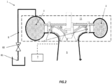
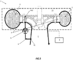
- FIG. 2 and 3 it is shown a front sectional view of a hydraulic installation 1, in particular a Francis turbine, according to a first embodiment of the present invention.
- the Francis turbine 1 differs from a known installation in that it comprises a first connecting element 8 fluidly connected to the hydraulic circuit, in particular to the spiral case 2, which has an end 81 discharging in the atmosphere.
- This first connecting element 8 with the exhaust at atmospheric pressure may be placed in addition or in alternative to the duct arranged between the spiral case and the draft tube (not shown) and it facilitates the process of reducing the pressure inside the spiral case 2.
- the spiral case 2 is provided with pressure sensors (not shown) arranged therein to monitor the pressure value during the condenser mode operational state.
- the first connecting element 8 may also be provided with an opening/closure valve 82 to control/adjust the discharge of water in atmosphere.
- the hydraulic installation 1 may comprise a second connecting element 6 arranged between the hydraulic circuit, and in particular the spiral case 2, and the draft tube 5.
- the second connecting element 6 comprises a pump 9 located along its path. This way, the flow of water from the spiral case 2 to the draft tube 5 is adjusted/regulated by means of the pump 9.
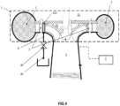
- the first connecting element 8 intercepts the hydraulic circuit in correspondence of a gap 411 located into the runner chamber 41, particularly between the wicket gates 3 and the runner 4.
- the second connecting element 6 intercepts the hydraulic circuit in correspondence of the gap 411 and has an end 61 discharging into the draft tube.
- the hydraulic installation comprises a first control unit 11, which is configured to receive an input signal correspondent to a pressure value from the pressure sensors 111 and elaborate an output control signal directed to the pump 9.
- the arrangement is such that the action of the pump to dewater the spiral case and thus reduce the pressure is regulated based on the pressure values measured in the spiral case during the condenser mode operation.
- hydraulic installation may comprise a second control unit 12 configured to receive an input signal correspondent to a pressure value from the pressure sensors 111 and elaborate an output control signal directed to the opening/closing valve 82.
- opening/closing valve 82 might have a mechanism such to allow partial closing/opening of the same, to further regulate the exhaust of water for dewatering the spiral case and hence gradually reducing its internal pressure.
- hydraulic installation may comprise a third control unit 13 configured to receive an input signal correspondent to a pressure value from the pressure sensors 111 and elaborate an output control signal directed to adjust the pitch of the wicket gates, which are indicated in the block with numeral reference 3. In this way, pressure inside the spiral case may also be regulated allowing the passage of the water flow into the runner.
- the method includes the step of connecting the first connecting element 8 to the hydraulic circuit, wherein the first connecting element has an end discharging in atmosphere.
- the first connecting element 8 may also be provided with an opening/closure valves 82 to further improve the process of dewatering the spiral case 2.
- the method may include the step of connecting a second connecting element 6 to the runner chamber, and in particular to the gap 411, located between the wicket gates and the runner, and providing a pump 9 along its path.
- the hydraulic installation comprises, with reference to figures 2-5 , a hydraulic circuit including a spiral casing 2 which defines an annular passage and a plurality of wicket gates distributed there along, wherein the wicked gates are provided with an adjustable pitch such to be moved between a totally open position, allowing water passage, and a closed position where the water passage is interrupted.
- the hydraulic installation further comprises a runner chamber in fluid communication with said spiral casing and located downstream of the wicket gates; a runner rotatable in the runner chamber; a draft tube arranged below the runner; a source of pressurised air in fluid communication with the draft tube 5; wherein the hydraulic installation comprises a first connecting element 6 arranged between the spiral casing 2 and having an end 81 discharging in atmosphere, the second duct 8 comprising an opening/closure valve 82; or a second connecting element 8 arranged between the hydraulic circuit 11 and the draft tube 5, the second connecting element 8 comprising a pump 9;
- the method for operating the hydraulic installation includes the step of measuring the pressure inside the spiral casing 2 and elaborating a control output signal, based on the pressure measurement, directed to adjust the pitch of the wicket gates or, in alternative, to control the opening/closure of the valve 82 or, in alternative, to regulate the pump 9.
Landscapes
- Engineering & Computer Science (AREA)
- Chemical & Material Sciences (AREA)
- Combustion & Propulsion (AREA)
- Mechanical Engineering (AREA)
- General Engineering & Computer Science (AREA)
- Hydraulic Turbines (AREA)
- Control Of Water Turbines (AREA)
- Control Of Turbines (AREA)
Description
- The present invention generally relates to hydraulic installations, such as hydraulic turbines. More specifically, the invention is directed to optimising power consumption when the turbine is used in condenser mode.
- As well known, it is common practise for Francis turbine to evacuate water from the runner when the generator is disconnected and thus electricity is not produced. This state of operation is generally referred to as "condenser mode", wherein the electrical output is not in the form of electric power. Nevertheless, the turbine is advantageously kept at a synchronous speed so that it can be quickly brought back to the normal operation mode, where the runner is connected to the generator and electric power is delivered.
- To this purpose, such condenser operation mode is achieved by closing the wicket gates and then admitting pressurised air into the runner housing.
- A technical problem which arises from such operational mode is that the pressure of the water inside the spiral case usually tends to reach high levels, which could affect the power consumption of the turbine. To this regard, a water passageway is usually provided between the summit of the spiral case and the underlying draft tube. This way, a flow of water naturally moves from the spiral case to the draft tube in the direction of a negative pressure gradient.
- However, such technical expedient does not provide a satisfying solution to the aforesaid technical problem, as it is proven that power consumption for state-of-the-art installations is still not optimal.
- JPS58106180 discloses a draining method in time of condenser operation on a reversible pump turbine.
- It is an object of the present invention to solve the aforementioned technical problems by providing a hydraulic installation as defined according to
independent claim 1. - It is a further object of the present invention to provide a method for operating a hydraulic installation as defined in independent claim 10.
- According to a preferred aspect of the invention, the first connecting element intercepts the hydraulic circuit in correspondence of the spiral casing.
- According to a preferred aspect of the invention, the first connecting element intercepts the hydraulic circuit in correspondence of a gap of the runner chamber, the gap being located between the wicket gates and the runner.
- According to a preferred aspect of the invention, the second connecting element intercepts the hydraulic circuit in correspondence of the spiral casing.
- According to a preferred aspect of the invention, the second connecting element intercepts the hydraulic circuit in correspondence of a gap of the runner chamber, the gap being located between the wicket gates and the runner.
- According to a preferred aspect of the invention, the hydraulic installation comprises a first control unit configured to receive an input signal correspondent to a pressure value from the pressure sensors and elaborate an output control signal directed to the pump.
- According to a preferred aspect of the invention, the wicket gates in the annular passage have an adjustable pitch such to be moved between an open position, allowing water passage to the runner, and a closed position where the water passage is interrupted.
- According to a preferred aspect of the invention, the hydraulic installation further comprises a third control unit configured to receive an input signal correspondent to a pressure value from the pressure sensors and elaborate an output control signal directed to adjust the pitch of the wicket gates.
- According to a preferred aspect of the invention, the first connecting element or the second connecting element intercepts the spiral casing at a summit thereof.
- According to a preferred aspect of the invention, the runner is located radially in the annular passage.
- The objects, advantages and other features of the present invention will become more apparent upon reading of the following non-restrictive description of preferred embodiments thereof, given for the purpose of exemplification only, with reference to the accompany drawing, through which similar reference numerals may be used to refer to similar elements, and in which:
-
Figure 1 shows a front sectional view of a hydraulic installation according to the prior art; -
Figures 2 - 5 show front sectional views of a hydraulic installation according to different embodiments of the present invention; -
Figures 6a - 6c show simplified block diagrams illustrating modes of operating the hydraulic installation according to the present invention. - An exemplary preferred embodiment will be now described with reference to the aforementioned drawings.
- With reference to
figure 1 , it is shown a hydraulic installation in front-sectional view, in particular a Francis or a reversible Francis-type turbine 100, according to the prior art. - In particular, Francis or reversible Francis
turbine 100 comprises a hydraulic circuit, generally indicated in the figure with a dashed box havingnumeral reference 11, which comprises aspiral casing 2 which defines a spiral passage where the water flows, and a plurality ofwicket gates 3 uniformly distributed there along. Radially located in the annular passage is arunner 4 which is put in rotation by the flow of water and located into arunner chamber 41. - The wicket gates provided in the annular passage have an adjustable pitch such to be moved between an open position, allowing passage of water, and a closed position where the flow of water is interrupted. Runner 4 is in turn integral to a
shaft 40 for the supply of electric power. - A
draft tube 5 is positioned below the runner, serving as a conduit which connects the exit of the runner to a tail race where the water is finally discharged. - When the Francis
turbine 100 is used in the so-called "condenser mode", dewatering ofrunner 4 is achieved by positioning the wicket gates in a closed configuration, such not to allow the passage of water. - Additionally, the
draft tube 5 is dewatered with the aid of a source of pressurisedair 7 in fluid communication with the draft tube. - During this mode of operation, where the
runner 4 is kept at synchronous speed, the pressure in thespiral case 2 may rise to levels which could cause an unwanted passage of water through the wicket gates. To this purpose, a duct 66 is arranged between thespiral case 2 and thedraft tube 5, and intercepts thespiral casing 2 at a summit thereof. By means of duct 66, water flows along a direction of a negative pressure gradient from the spiral case to the draft tube. This way the pressure in thespiral case 2 is reduced. However, it has proven that such solution does not solve in a satisfactory manner such technical problem because residual water rises in the space betweenrunner 4 and the wicket gate. The residual water is responsible on the main part of the total installation active power consumption. - With reference to
figure 2 and3 , it is shown a front sectional view of ahydraulic installation 1, in particular a Francis turbine, according to a first embodiment of the present invention. - The Francis
turbine 1 according to the invention differs from a known installation in that it comprises a first connectingelement 8 fluidly connected to the hydraulic circuit, in particular to thespiral case 2, which has anend 81 discharging in the atmosphere. This first connectingelement 8 with the exhaust at atmospheric pressure may be placed in addition or in alternative to the duct arranged between the spiral case and the draft tube (not shown) and it facilitates the process of reducing the pressure inside thespiral case 2. Thespiral case 2 is provided with pressure sensors (not shown) arranged therein to monitor the pressure value during the condenser mode operational state. - The first connecting
element 8 may also be provided with an opening/closure valve 82 to control/adjust the discharge of water in atmosphere. - In alternative, with reference to
figure 3 thehydraulic installation 1 may comprise a second connectingelement 6 arranged between the hydraulic circuit, and in particular thespiral case 2, and thedraft tube 5. The second connectingelement 6 comprises apump 9 located along its path. This way, the flow of water from thespiral case 2 to thedraft tube 5 is adjusted/regulated by means of thepump 9. - With reference to following
figures 4 and5 , it is shown a hydraulic installation according to a second embodiment of the present invention. - More in particular, with reference to
figure 4 , the first connectingelement 8 intercepts the hydraulic circuit in correspondence of agap 411 located into therunner chamber 41, particularly between thewicket gates 3 and therunner 4. Turning to nextfigure 5 , the second connectingelement 6 intercepts the hydraulic circuit in correspondence of thegap 411 and has anend 61 discharging into the draft tube. - Making now reference to next
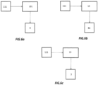
figures 6a-6c , it is shown in a simplified block diagram an exemplary control logic adopted to monitor and regulate/adjust the pressure in the spiral case particularly during condenser mode operation of the Francis turbine. - According to
figure 6a , the hydraulic installation comprises afirst control unit 11, which is configured to receive an input signal correspondent to a pressure value from thepressure sensors 111 and elaborate an output control signal directed to thepump 9. The arrangement is such that the action of the pump to dewater the spiral case and thus reduce the pressure is regulated based on the pressure values measured in the spiral case during the condenser mode operation. - In alternative, with reference to
figure 6b , hydraulic installation may comprise asecond control unit 12 configured to receive an input signal correspondent to a pressure value from thepressure sensors 111 and elaborate an output control signal directed to the opening/closing valve 82. In particular, opening/closing valve 82 might have a mechanism such to allow partial closing/opening of the same, to further regulate the exhaust of water for dewatering the spiral case and hence gradually reducing its internal pressure. Alternatively or additionally, hydraulic installation may comprise athird control unit 13 configured to receive an input signal correspondent to a pressure value from thepressure sensors 111 and elaborate an output control signal directed to adjust the pitch of the wicket gates, which are indicated in the block withnumeral reference 3. In this way, pressure inside the spiral case may also be regulated allowing the passage of the water flow into the runner. - It is a further object of the description, not covered by the claims, to provide a method for retrofitting an existing hydraulic installation according to the state of the art, as the one described with reference to
figure 1 . - In particular, the method includes the step of connecting the first connecting
element 8 to the hydraulic circuit, wherein the first connecting element has an end discharging in atmosphere. The first connectingelement 8 may also be provided with an opening/closure valves 82 to further improve the process of dewatering thespiral case 2. - Alternatively, the method may include the step of connecting a second connecting
element 6 to the runner chamber, and in particular to thegap 411, located between the wicket gates and the runner, and providing apump 9 along its path. - As a further object of the present invention, it is provided method for operating a hydraulic installation, whereby the hydraulic installation comprises, with reference to
figures 2-5 , a hydraulic circuit including aspiral casing 2 which defines an annular passage and a plurality of wicket gates distributed there along, wherein the wicked gates are provided with an adjustable pitch such to be moved between a totally open position, allowing water passage, and a closed position where the water passage is interrupted. The hydraulic installation further comprises a runner chamber in fluid communication with said spiral casing and located downstream of the wicket gates; a runner rotatable in the runner chamber; a draft tube arranged below the runner; a source of pressurised air in fluid communication with thedraft tube 5; wherein the hydraulic installation comprises a first connectingelement 6 arranged between thespiral casing 2 and having anend 81 discharging in atmosphere, thesecond duct 8 comprising an opening/closure valve 82; or a second connectingelement 8 arranged between thehydraulic circuit 11 and thedraft tube 5, the second connectingelement 8 comprising apump 9; - The method for operating the hydraulic installation includes the step of measuring the pressure inside the
spiral casing 2 and elaborating a control output signal, based on the pressure measurement, directed to adjust the pitch of the wicket gates or, in alternative, to control the opening/closure of thevalve 82 or, in alternative, to regulate thepump 9.
Claims (10)
- A hydraulic installation (1), comprising:- a hydraulic circuit (11) comprising: a spiral casing (2) which defines an annular passage (10) including a plurality of wicket gates (3) distributed there along;- a runner chamber (41) in fluid communication with said spiral casing (2) and located downstream of said wicket gates (3);- a runner (4) rotatable in said runner chamber (41);- a draft tube (5) arranged below said runner (4);- a source of pressurised air (7) in fluid communication with said draft tube (5);the hydraulic installation comprising a first connecting element (8) fluidly connected to said hydraulic circuit (11), said first connecting element (8) comprising an opening/closure valve (82) and having an end (81) discharging in atmosphere or, in alternative to said first connecting element (8), a second connecting element (6) fluidly connected to said hydraulic circuit (11) and having an end (61) discharging in said draft tube (5), wherein said second connecting element comprises a pump (9)characterised in that the hydraulic installation further comprises one or more pressure sensors (111) arranged within said spiral case (2) andif the hydraulic installation comprises said first connecting element (8): a first control unit (12) configured to receive an input signal correspondent to a pressure value from said pressure sensors (111) and elaborate an output control signal directed to said opening/closure valve (82).
- The hydraulic installation (1) according to the preceding claim, wherein said first connecting element (8) intercepts said hydraulic circuit (11) in correspondence of said spiral casing (2).
- The hydraulic installation (1) according to claim 1, wherein said first connecting element (8) intercepts said hydraulic circuit (11) in correspondence of a gap (411) of said runner chamber (41), the gap being located between said wicket gates (3) and said runner (4).
- The hydraulic installation (1) according to claim 1, wherein said second connecting element (6) intercepts said hydraulic circuit (11) in correspondence of said spiral casing (2).
- The hydraulic installation (1) according to claim 1, wherein said second connecting element (6) intercepts said hydraulic circuit (11) in correspondence of a gap (411) of said runner chamber (41), the gap (411) being located between said wicket gates (3) and said runner (4).
- The hydraulic installation (1) according to any of the preceding claims, further comprising a second control unit (101) configured to receive an input signal correspondent to a pressure value from said pressure sensors (111) and elaborate an output control signal directed to said pump (9).
- The hydraulic installation (1) according to any of the preceding claims, wherein said wicket gates (3) in said annular passage (10) have an adjustable pitch such to be moved between a totally open position, allowing water passage to said runner (4), and a closed position where the water passage is interrupted.
- The hydraulic installation (1) according to claims 1 and 7, further comprising a third control unit (13) configured to receive an input signal correspondent to a pressure value from said pressure sensors (111) and elaborate an output control signal directed to adjust the pitch of said wicket gates (3).
- The hydraulic installation (1) according to the preceding claim, wherein said first or second connecting element (6) intercepts said hydraulic circuit (11) in correspondence of a summit (21) of said spiral casing (2).
- Method for operating a hydraulic installation, the hydraulic installation comprising:- a hydraulic circuit (11) comprising: a spiral casing (2) which defines an annular passage (10) including a plurality of wicket gates (3) distributed there along, the wicket gates (3) having an adjustable pitch;- a runner chamber (41) in fluid communication with said spiral casing (2) and located downstream of said wicket gates (3);- a runner (4) rotatable in said runner chamber (41);- a draft tube (5) arranged below said runner (4);- a source of pressurised air (7) in fluid communication with said draft tube (5);wherein the hydraulic installation (1) comprises:- a first connecting element (8) arranged between said spiral casing (2) and having an end (81) discharging in atmosphere, said first connecting element (8) comprising an opening/closure valve (82); or- a second connecting element (6) arranged between said hydraulic circuit (11) and said draft tube (5), said second connecting element (6) comprising a pump (9);wherein said method includes the step of measuring the pressure with one or more pressure sensors (111) inside said spiral casing (2) and elaborate a control output signal, based on said pressure measurement, directed to adjust the pitch of said wicket gates (3) or to control the opening/closure of said valve (82) or to regulate said pump (9).
Priority Applications (6)
| Application Number | Priority Date | Filing Date | Title |
|---|---|---|---|
| EP15290230.0A EP3141739B2 (en) | 2015-09-14 | 2015-09-14 | Hydraulic installation and method for operating the same |
| CA2998441A CA2998441C (en) | 2015-09-14 | 2016-09-09 | Hydraulic installation and method for operating the same |
| CN201680053294.1A CN108026891B (en) | 2015-09-14 | 2016-09-09 | Hydraulic equipment and method for operating hydraulic equipment |
| BR112018004465-2A BR112018004465B1 (en) | 2015-09-14 | 2016-09-09 | HYDRAULIC INSTALLATION, METHOD FOR READAPTING A HYDRAULIC INSTALLATION AND METHOD FOR OPERATING A HYDRAULIC INSTALLATION |
| PCT/EP2016/071315 WO2017046012A1 (en) | 2015-09-14 | 2016-09-09 | Hydraulic installation and method for operating the same |
| US15/759,885 US10907608B2 (en) | 2015-09-14 | 2016-09-09 | Hydraulic installation and method for operating the same |
Applications Claiming Priority (1)
| Application Number | Priority Date | Filing Date | Title |
|---|---|---|---|
| EP15290230.0A EP3141739B2 (en) | 2015-09-14 | 2015-09-14 | Hydraulic installation and method for operating the same |
Publications (3)
| Publication Number | Publication Date |
|---|---|
| EP3141739A1 EP3141739A1 (en) | 2017-03-15 |
| EP3141739B1 EP3141739B1 (en) | 2020-01-22 |
| EP3141739B2 true EP3141739B2 (en) | 2023-03-15 |
Family
ID=54291205
Family Applications (1)
| Application Number | Title | Priority Date | Filing Date |
|---|---|---|---|
| EP15290230.0A Active EP3141739B2 (en) | 2015-09-14 | 2015-09-14 | Hydraulic installation and method for operating the same |
Country Status (6)
| Country | Link |
|---|---|
| US (1) | US10907608B2 (en) |
| EP (1) | EP3141739B2 (en) |
| CN (1) | CN108026891B (en) |
| BR (1) | BR112018004465B1 (en) |
| CA (1) | CA2998441C (en) |
| WO (1) | WO2017046012A1 (en) |
Citations (2)
| Publication number | Priority date | Publication date | Assignee | Title |
|---|---|---|---|---|
| US3658436A (en) † | 1969-03-10 | 1972-04-25 | Hitachi Ltd | Water turbine operation method and system |
| JPS5372942A (en) † | 1976-12-10 | 1978-06-28 | Hitachi Ltd | Hydraulic machine operation |
Family Cites Families (24)
| Publication number | Priority date | Publication date | Assignee | Title |
|---|---|---|---|---|
| US3174719A (en) * | 1962-06-12 | 1965-03-23 | Dominion Eng Works Ltd | Francis turbines and centrifugal pumps |
| GB1047014A (en) * | 1962-07-03 | 1966-11-02 | English Electric Co Ltd | Improvements in or relating to hydraulic pumps, turbines or reversible pump turbines |
| GB1060395A (en) * | 1962-10-02 | 1967-03-01 | Hitachi Ltd | Methods and apparatus for reducing water hammer in the tailrace or suction line of a water turbine, pump turbine, or pump |
| US3307828A (en) * | 1966-06-29 | 1967-03-07 | Baldwin Lima Hamilton Corp | Torque reducing means |
| JPS4910206B1 (en) | 1969-09-12 | 1974-03-08 | ||
| JPS5058441A (en) * | 1973-09-26 | 1975-05-21 | ||
| JPS5146504A (en) | 1974-10-21 | 1976-04-21 | Komatsu Mfg Co Ltd | JIBANKUTSUSAKUSOCHI |
| JPS5346533A (en) * | 1976-10-08 | 1978-04-26 | Hitachi Ltd | Operating method of hydraulic machinery |
| JPS5395447A (en) * | 1977-01-31 | 1978-08-21 | Toshiba Corp | Operation of reversible pump-turbine |
| JPS6054515B2 (en) * | 1978-06-30 | 1985-11-30 | 株式会社東芝 | hydraulic machinery |
| JPS56107972A (en) | 1980-01-30 | 1981-08-27 | Toshiba Corp | Operation control device for hydraulic machinery |
| JPS57181974A (en) * | 1981-04-30 | 1982-11-09 | Toshiba Corp | Idle running device of water turbine or pump-turbine |
| JPS58106180A (en) * | 1981-12-18 | 1983-06-24 | Mitsubishi Heavy Ind Ltd | Draining method in time of condenser operation on reversible pump-turbine |
| JPH0830462B2 (en) | 1987-05-08 | 1996-03-27 | 株式会社東芝 | How to start pumping a variable speed pump turbine or pump |
| JP3917292B2 (en) * | 1998-05-08 | 2007-05-23 | 株式会社東芝 | Operation method of hydraulic machine |
| JP2001165024A (en) * | 1999-12-14 | 2001-06-19 | Toshiba Corp | Francis type hydraulic machine |
| CA2549749C (en) * | 2006-06-09 | 2015-05-19 | General Electric Company | Control jet for hydraulic turbine |
| FR2923553A1 (en) * | 2007-11-14 | 2009-05-15 | Alstom Power Hydraulique Sa | HYDRAULIC ENERGY CONVERSION INSTALLATION AND METHOD OF CONTROLLING SUCH INSTALLATION |
| FR2942274B1 (en) * | 2009-02-18 | 2014-04-18 | Alstom Hydro France | HYDRAULIC ENERGY CONVERSION INSTALLATION AND METHOD OF CONTROLLING SUCH INSTALLATION |
| NO20092663A (en) * | 2009-07-14 | 2010-11-22 | Dynavec As | Method and device for counteracting wear around a guide vane |
| NO20092682A (en) * | 2009-07-15 | 2010-11-22 | Dynavec As | Method and device for counteracting wear from particulate drift water in an impeller |
| JP5956885B2 (en) * | 2012-09-19 | 2016-07-27 | 株式会社東芝 | Hydraulic machine and operation method thereof |
| EP2976522B1 (en) * | 2013-03-19 | 2018-05-16 | GE Renewable Technologies | Hydraulic turbine, and power conversion facility including such a turbine |
| JP2016173075A (en) * | 2015-03-17 | 2016-09-29 | 株式会社東芝 | Hydraulic machinery and operation method of the same |
-
2015
- 2015-09-14 EP EP15290230.0A patent/EP3141739B2/en active Active
-
2016
- 2016-09-09 CN CN201680053294.1A patent/CN108026891B/en active Active
- 2016-09-09 BR BR112018004465-2A patent/BR112018004465B1/en active IP Right Grant
- 2016-09-09 CA CA2998441A patent/CA2998441C/en active Active
- 2016-09-09 WO PCT/EP2016/071315 patent/WO2017046012A1/en not_active Ceased
- 2016-09-09 US US15/759,885 patent/US10907608B2/en active Active
Patent Citations (2)
| Publication number | Priority date | Publication date | Assignee | Title |
|---|---|---|---|---|
| US3658436A (en) † | 1969-03-10 | 1972-04-25 | Hitachi Ltd | Water turbine operation method and system |
| JPS5372942A (en) † | 1976-12-10 | 1978-06-28 | Hitachi Ltd | Hydraulic machine operation |
Non-Patent Citations (1)
| Title |
|---|
| D KLEMM: "Untersuchung der Vorgänge beim Ausblasen und Füllen einer Pumpturbine", VOITH, vol. 27, no. 2, 1 January 1980 (1980-01-01), pages 2.2 - 2.7 † |
Also Published As
| Publication number | Publication date |
|---|---|
| EP3141739B1 (en) | 2020-01-22 |
| US20180252198A1 (en) | 2018-09-06 |
| BR112018004465B1 (en) | 2023-01-10 |
| WO2017046012A1 (en) | 2017-03-23 |
| CA2998441A1 (en) | 2017-03-23 |
| EP3141739A1 (en) | 2017-03-15 |
| US10907608B2 (en) | 2021-02-02 |
| CN108026891A (en) | 2018-05-11 |
| CA2998441C (en) | 2023-10-17 |
| CN108026891B (en) | 2020-11-03 |
| BR112018004465A2 (en) | 2018-09-25 |
Similar Documents
| Publication | Publication Date | Title |
|---|---|---|
| US20100290889A1 (en) | Turbine wheelspace temperature control | |
| US3658436A (en) | Water turbine operation method and system | |
| KR101666318B1 (en) | Pumpgate system having small hydropower generating | |
| JP2014518349A (en) | Pump turbine equipment | |
| CN105143606B (en) | For balancing method, turbine and the turbogenerator of thrust | |
| EP3141739B2 (en) | Hydraulic installation and method for operating the same | |
| RU2658721C2 (en) | Power machine with fluid medium with “tandem” type double dry gas seal | |
| WO2014155656A1 (en) | Sustained-flow-rate power generation control system, sustained-flow-rate power generation control method, sustained-flow-rate power generation control program, and sustained-flow-rate power generation facility | |
| US10494947B2 (en) | Operation method for steam turbine, and steam turbine | |
| JP6884683B2 (en) | Hydraulic machinery thrust control system and hydraulic machinery | |
| CN203516128U (en) | Diving gate pump | |
| EP2599964B1 (en) | Steam turbine arrangement of a three casing steam turbine | |
| US4431370A (en) | Multistage hydraulic machines having air exhausting devices | |
| CA3048394C (en) | Power generation plant having a kaplan, bulb, diagonal flow or propeller turbine | |
| KR101908867B1 (en) | Small Hydro Power Device using waterworks | |
| JP6433269B2 (en) | Pump reverse turbine type power generator | |
| CN115681191B (en) | Sealed fan control method, device, storage medium and electronic equipment | |
| JP2007120459A (en) | Guide vane closing control device for power generation hydraulic machine and control method therefor | |
| JP2007255315A (en) | Francis turbine for hydropower | |
| CN209742977U (en) | Gland sealing pressure control device of condensing steam turbine | |
| JP2010150943A (en) | Hydroelectric system | |
| JP2008248787A (en) | How to drive a water wheel | |
| PH12018000172A1 (en) | Extraction control method for steam turbine generator | |
| JPS5911750B2 (en) | Idle torque adjustment method and device for hydraulic machinery | |
| JPH05248337A (en) | Guide vane of hydraulic turbine and controller of pressure regulator |
Legal Events
| Date | Code | Title | Description |
|---|---|---|---|
| PUAI | Public reference made under article 153(3) epc to a published international application that has entered the european phase |
Free format text: ORIGINAL CODE: 0009012 |
|
| STAA | Information on the status of an ep patent application or granted ep patent |
Free format text: STATUS: THE APPLICATION HAS BEEN PUBLISHED |
|
| AK | Designated contracting states |
Kind code of ref document: A1 Designated state(s): AL AT BE BG CH CY CZ DE DK EE ES FI FR GB GR HR HU IE IS IT LI LT LU LV MC MK MT NL NO PL PT RO RS SE SI SK SM TR |
|
| AX | Request for extension of the european patent |
Extension state: BA ME |
|
| RAP1 | Party data changed (applicant data changed or rights of an application transferred) |
Owner name: GE RENEWABLE TECHNOLOGIES |
|
| STAA | Information on the status of an ep patent application or granted ep patent |
Free format text: STATUS: REQUEST FOR EXAMINATION WAS MADE |
|
| 17P | Request for examination filed |
Effective date: 20170915 |
|
| RBV | Designated contracting states (corrected) |
Designated state(s): AL AT BE BG CH CY CZ DE DK EE ES FI FR GB GR HR HU IE IS IT LI LT LU LV MC MK MT NL NO PL PT RO RS SE SI SK SM TR |
|
| STAA | Information on the status of an ep patent application or granted ep patent |
Free format text: STATUS: EXAMINATION IS IN PROGRESS |
|
| 17Q | First examination report despatched |
Effective date: 20180516 |
|
| GRAP | Despatch of communication of intention to grant a patent |
Free format text: ORIGINAL CODE: EPIDOSNIGR1 |
|
| STAA | Information on the status of an ep patent application or granted ep patent |
Free format text: STATUS: GRANT OF PATENT IS INTENDED |
|
| INTG | Intention to grant announced |
Effective date: 20190703 |
|
| GRAS | Grant fee paid |
Free format text: ORIGINAL CODE: EPIDOSNIGR3 |
|
| GRAJ | Information related to disapproval of communication of intention to grant by the applicant or resumption of examination proceedings by the epo deleted |
Free format text: ORIGINAL CODE: EPIDOSDIGR1 |
|
| GRAL | Information related to payment of fee for publishing/printing deleted |
Free format text: ORIGINAL CODE: EPIDOSDIGR3 |
|
| STAA | Information on the status of an ep patent application or granted ep patent |
Free format text: STATUS: EXAMINATION IS IN PROGRESS |
|
| GRAR | Information related to intention to grant a patent recorded |
Free format text: ORIGINAL CODE: EPIDOSNIGR71 |
|
| STAA | Information on the status of an ep patent application or granted ep patent |
Free format text: STATUS: GRANT OF PATENT IS INTENDED |
|
| INTC | Intention to grant announced (deleted) | ||
| GRAA | (expected) grant |
Free format text: ORIGINAL CODE: 0009210 |
|
| STAA | Information on the status of an ep patent application or granted ep patent |
Free format text: STATUS: THE PATENT HAS BEEN GRANTED |
|
| INTG | Intention to grant announced |
Effective date: 20191206 |
|
| AK | Designated contracting states |
Kind code of ref document: B1 Designated state(s): AL AT BE BG CH CY CZ DE DK EE ES FI FR GB GR HR HU IE IS IT LI LT LU LV MC MK MT NL NO PL PT RO RS SE SI SK SM TR |
|
| REG | Reference to a national code |
Ref country code: GB Ref legal event code: FG4D |
|
| REG | Reference to a national code |
Ref country code: CH Ref legal event code: EP |
|
| REG | Reference to a national code |
Ref country code: DE Ref legal event code: R096 Ref document number: 602015045940 Country of ref document: DE |
|
| REG | Reference to a national code |
Ref country code: AT Ref legal event code: REF Ref document number: 1227062 Country of ref document: AT Kind code of ref document: T Effective date: 20200215 |
|
| REG | Reference to a national code |
Ref country code: IE Ref legal event code: FG4D |
|
| REG | Reference to a national code |
Ref country code: NL Ref legal event code: MP Effective date: 20200122 |
|
| REG | Reference to a national code |
Ref country code: LT Ref legal event code: MG4D |
|
| PG25 | Lapsed in a contracting state [announced via postgrant information from national office to epo] |
Ref country code: NO Free format text: LAPSE BECAUSE OF FAILURE TO SUBMIT A TRANSLATION OF THE DESCRIPTION OR TO PAY THE FEE WITHIN THE PRESCRIBED TIME-LIMIT Effective date: 20200422 Ref country code: RS Free format text: LAPSE BECAUSE OF FAILURE TO SUBMIT A TRANSLATION OF THE DESCRIPTION OR TO PAY THE FEE WITHIN THE PRESCRIBED TIME-LIMIT Effective date: 20200122 Ref country code: FI Free format text: LAPSE BECAUSE OF FAILURE TO SUBMIT A TRANSLATION OF THE DESCRIPTION OR TO PAY THE FEE WITHIN THE PRESCRIBED TIME-LIMIT Effective date: 20200122 Ref country code: NL Free format text: LAPSE BECAUSE OF FAILURE TO SUBMIT A TRANSLATION OF THE DESCRIPTION OR TO PAY THE FEE WITHIN THE PRESCRIBED TIME-LIMIT Effective date: 20200122 Ref country code: PT Free format text: LAPSE BECAUSE OF FAILURE TO SUBMIT A TRANSLATION OF THE DESCRIPTION OR TO PAY THE FEE WITHIN THE PRESCRIBED TIME-LIMIT Effective date: 20200614 |
|
| PG25 | Lapsed in a contracting state [announced via postgrant information from national office to epo] |
Ref country code: LV Free format text: LAPSE BECAUSE OF FAILURE TO SUBMIT A TRANSLATION OF THE DESCRIPTION OR TO PAY THE FEE WITHIN THE PRESCRIBED TIME-LIMIT Effective date: 20200122 Ref country code: IS Free format text: LAPSE BECAUSE OF FAILURE TO SUBMIT A TRANSLATION OF THE DESCRIPTION OR TO PAY THE FEE WITHIN THE PRESCRIBED TIME-LIMIT Effective date: 20200522 Ref country code: SE Free format text: LAPSE BECAUSE OF FAILURE TO SUBMIT A TRANSLATION OF THE DESCRIPTION OR TO PAY THE FEE WITHIN THE PRESCRIBED TIME-LIMIT Effective date: 20200122 Ref country code: GR Free format text: LAPSE BECAUSE OF FAILURE TO SUBMIT A TRANSLATION OF THE DESCRIPTION OR TO PAY THE FEE WITHIN THE PRESCRIBED TIME-LIMIT Effective date: 20200423 Ref country code: HR Free format text: LAPSE BECAUSE OF FAILURE TO SUBMIT A TRANSLATION OF THE DESCRIPTION OR TO PAY THE FEE WITHIN THE PRESCRIBED TIME-LIMIT Effective date: 20200122 Ref country code: BG Free format text: LAPSE BECAUSE OF FAILURE TO SUBMIT A TRANSLATION OF THE DESCRIPTION OR TO PAY THE FEE WITHIN THE PRESCRIBED TIME-LIMIT Effective date: 20200422 |
|
| REG | Reference to a national code |
Ref country code: DE Ref legal event code: R026 Ref document number: 602015045940 Country of ref document: DE |
|
| PLBI | Opposition filed |
Free format text: ORIGINAL CODE: 0009260 |
|
| PG25 | Lapsed in a contracting state [announced via postgrant information from national office to epo] |
Ref country code: EE Free format text: LAPSE BECAUSE OF FAILURE TO SUBMIT A TRANSLATION OF THE DESCRIPTION OR TO PAY THE FEE WITHIN THE PRESCRIBED TIME-LIMIT Effective date: 20200122 Ref country code: ES Free format text: LAPSE BECAUSE OF FAILURE TO SUBMIT A TRANSLATION OF THE DESCRIPTION OR TO PAY THE FEE WITHIN THE PRESCRIBED TIME-LIMIT Effective date: 20200122 Ref country code: LT Free format text: LAPSE BECAUSE OF FAILURE TO SUBMIT A TRANSLATION OF THE DESCRIPTION OR TO PAY THE FEE WITHIN THE PRESCRIBED TIME-LIMIT Effective date: 20200122 Ref country code: CZ Free format text: LAPSE BECAUSE OF FAILURE TO SUBMIT A TRANSLATION OF THE DESCRIPTION OR TO PAY THE FEE WITHIN THE PRESCRIBED TIME-LIMIT Effective date: 20200122 Ref country code: RO Free format text: LAPSE BECAUSE OF FAILURE TO SUBMIT A TRANSLATION OF THE DESCRIPTION OR TO PAY THE FEE WITHIN THE PRESCRIBED TIME-LIMIT Effective date: 20200122 Ref country code: SK Free format text: LAPSE BECAUSE OF FAILURE TO SUBMIT A TRANSLATION OF THE DESCRIPTION OR TO PAY THE FEE WITHIN THE PRESCRIBED TIME-LIMIT Effective date: 20200122 Ref country code: SM Free format text: LAPSE BECAUSE OF FAILURE TO SUBMIT A TRANSLATION OF THE DESCRIPTION OR TO PAY THE FEE WITHIN THE PRESCRIBED TIME-LIMIT Effective date: 20200122 Ref country code: DK Free format text: LAPSE BECAUSE OF FAILURE TO SUBMIT A TRANSLATION OF THE DESCRIPTION OR TO PAY THE FEE WITHIN THE PRESCRIBED TIME-LIMIT Effective date: 20200122 |
|
| 26 | Opposition filed |
Opponent name: VOITH PATENT GMBH Effective date: 20201006 |
|
| PLAX | Notice of opposition and request to file observation + time limit sent |
Free format text: ORIGINAL CODE: EPIDOSNOBS2 |
|
| PG25 | Lapsed in a contracting state [announced via postgrant information from national office to epo] |
Ref country code: IT Free format text: LAPSE BECAUSE OF FAILURE TO SUBMIT A TRANSLATION OF THE DESCRIPTION OR TO PAY THE FEE WITHIN THE PRESCRIBED TIME-LIMIT Effective date: 20200122 |
|
| PG25 | Lapsed in a contracting state [announced via postgrant information from national office to epo] |
Ref country code: SI Free format text: LAPSE BECAUSE OF FAILURE TO SUBMIT A TRANSLATION OF THE DESCRIPTION OR TO PAY THE FEE WITHIN THE PRESCRIBED TIME-LIMIT Effective date: 20200122 Ref country code: PL Free format text: LAPSE BECAUSE OF FAILURE TO SUBMIT A TRANSLATION OF THE DESCRIPTION OR TO PAY THE FEE WITHIN THE PRESCRIBED TIME-LIMIT Effective date: 20200122 |
|
| PLBB | Reply of patent proprietor to notice(s) of opposition received |
Free format text: ORIGINAL CODE: EPIDOSNOBS3 |
|
| PG25 | Lapsed in a contracting state [announced via postgrant information from national office to epo] |
Ref country code: MC Free format text: LAPSE BECAUSE OF FAILURE TO SUBMIT A TRANSLATION OF THE DESCRIPTION OR TO PAY THE FEE WITHIN THE PRESCRIBED TIME-LIMIT Effective date: 20200122 |
|
| GBPC | Gb: european patent ceased through non-payment of renewal fee |
Effective date: 20200914 |
|
| REG | Reference to a national code |
Ref country code: BE Ref legal event code: MM Effective date: 20200930 |
|
| PG25 | Lapsed in a contracting state [announced via postgrant information from national office to epo] |
Ref country code: LU Free format text: LAPSE BECAUSE OF NON-PAYMENT OF DUE FEES Effective date: 20200914 |
|
| PG25 | Lapsed in a contracting state [announced via postgrant information from national office to epo] |
Ref country code: BE Free format text: LAPSE BECAUSE OF NON-PAYMENT OF DUE FEES Effective date: 20200930 Ref country code: GB Free format text: LAPSE BECAUSE OF NON-PAYMENT OF DUE FEES Effective date: 20200914 Ref country code: IE Free format text: LAPSE BECAUSE OF NON-PAYMENT OF DUE FEES Effective date: 20200914 |
|
| PG25 | Lapsed in a contracting state [announced via postgrant information from national office to epo] |
Ref country code: TR Free format text: LAPSE BECAUSE OF FAILURE TO SUBMIT A TRANSLATION OF THE DESCRIPTION OR TO PAY THE FEE WITHIN THE PRESCRIBED TIME-LIMIT Effective date: 20200122 Ref country code: MT Free format text: LAPSE BECAUSE OF FAILURE TO SUBMIT A TRANSLATION OF THE DESCRIPTION OR TO PAY THE FEE WITHIN THE PRESCRIBED TIME-LIMIT Effective date: 20200122 Ref country code: CY Free format text: LAPSE BECAUSE OF FAILURE TO SUBMIT A TRANSLATION OF THE DESCRIPTION OR TO PAY THE FEE WITHIN THE PRESCRIBED TIME-LIMIT Effective date: 20200122 |
|
| PG25 | Lapsed in a contracting state [announced via postgrant information from national office to epo] |
Ref country code: MK Free format text: LAPSE BECAUSE OF FAILURE TO SUBMIT A TRANSLATION OF THE DESCRIPTION OR TO PAY THE FEE WITHIN THE PRESCRIBED TIME-LIMIT Effective date: 20200122 Ref country code: AL Free format text: LAPSE BECAUSE OF FAILURE TO SUBMIT A TRANSLATION OF THE DESCRIPTION OR TO PAY THE FEE WITHIN THE PRESCRIBED TIME-LIMIT Effective date: 20200122 |
|
| APAH | Appeal reference modified |
Free format text: ORIGINAL CODE: EPIDOSCREFNO |
|
| APBM | Appeal reference recorded |
Free format text: ORIGINAL CODE: EPIDOSNREFNO |
|
| APBP | Date of receipt of notice of appeal recorded |
Free format text: ORIGINAL CODE: EPIDOSNNOA2O |
|
| APBU | Appeal procedure closed |
Free format text: ORIGINAL CODE: EPIDOSNNOA9O |
|
| REG | Reference to a national code |
Ref country code: AT Ref legal event code: UEP Ref document number: 1227062 Country of ref document: AT Kind code of ref document: T Effective date: 20200122 |
|
| PUAH | Patent maintained in amended form |
Free format text: ORIGINAL CODE: 0009272 |
|
| STAA | Information on the status of an ep patent application or granted ep patent |
Free format text: STATUS: PATENT MAINTAINED AS AMENDED |
|
| 27A | Patent maintained in amended form |
Effective date: 20230315 |
|
| AK | Designated contracting states |
Kind code of ref document: B2 Designated state(s): AL AT BE BG CH CY CZ DE DK EE ES FI FR GB GR HR HU IE IS IT LI LT LU LV MC MK MT NL NO PL PT RO RS SE SI SK SM TR |
|
| REG | Reference to a national code |
Ref country code: DE Ref legal event code: R102 Ref document number: 602015045940 Country of ref document: DE |
|
| P01 | Opt-out of the competence of the unified patent court (upc) registered |
Effective date: 20230522 |
|
| REG | Reference to a national code |
Ref country code: CH Ref legal event code: U11 Free format text: ST27 STATUS EVENT CODE: U-0-0-U10-U11 (AS PROVIDED BY THE NATIONAL OFFICE) Effective date: 20251001 |
|
| PGFP | Annual fee paid to national office [announced via postgrant information from national office to epo] |
Ref country code: DE Payment date: 20250820 Year of fee payment: 11 |
|
| PGFP | Annual fee paid to national office [announced via postgrant information from national office to epo] |
Ref country code: FR Payment date: 20250820 Year of fee payment: 11 Ref country code: AT Payment date: 20250822 Year of fee payment: 11 |
|
| PGFP | Annual fee paid to national office [announced via postgrant information from national office to epo] |
Ref country code: CH Payment date: 20251001 Year of fee payment: 11 |