EP3141383A1 - Tire-trimming device and method - Google Patents
Tire-trimming device and method Download PDFInfo
- Publication number
- EP3141383A1 EP3141383A1 EP15788705.0A EP15788705A EP3141383A1 EP 3141383 A1 EP3141383 A1 EP 3141383A1 EP 15788705 A EP15788705 A EP 15788705A EP 3141383 A1 EP3141383 A1 EP 3141383A1
- Authority
- EP
- European Patent Office
- Prior art keywords
- tire
- trimming
- trimming tool
- profile
- rubber components
- Prior art date
- Legal status (The legal status is an assumption and is not a legal conclusion. Google has not performed a legal analysis and makes no representation as to the accuracy of the status listed.)
- Withdrawn
Links
- 238000009966 trimming Methods 0.000 title claims abstract description 130
- 238000000034 method Methods 0.000 title claims abstract description 36
- 238000001514 detection method Methods 0.000 claims description 15
- 230000002093 peripheral effect Effects 0.000 claims description 13
- 239000006061 abrasive grain Substances 0.000 description 3
- 239000004677 Nylon Substances 0.000 description 2
- 229920001778 nylon Polymers 0.000 description 2
- 230000003287 optical effect Effects 0.000 description 2
- 238000005452 bending Methods 0.000 description 1
- 238000007796 conventional method Methods 0.000 description 1
- 239000013256 coordination polymer Substances 0.000 description 1
- 230000000694 effects Effects 0.000 description 1
- 239000000835 fiber Substances 0.000 description 1
- 238000005259 measurement Methods 0.000 description 1
- TWNQGVIAIRXVLR-UHFFFAOYSA-N oxo(oxoalumanyloxy)alumane Chemical compound O=[Al]O[Al]=O TWNQGVIAIRXVLR-UHFFFAOYSA-N 0.000 description 1
- HBMJWWWQQXIZIP-UHFFFAOYSA-N silicon carbide Chemical compound [Si+]#[C-] HBMJWWWQQXIZIP-UHFFFAOYSA-N 0.000 description 1
- 229910010271 silicon carbide Inorganic materials 0.000 description 1
- 230000002195 synergetic effect Effects 0.000 description 1
Images



Classifications
-
- B—PERFORMING OPERATIONS; TRANSPORTING
- B29—WORKING OF PLASTICS; WORKING OF SUBSTANCES IN A PLASTIC STATE IN GENERAL
- B29D—PRODUCING PARTICULAR ARTICLES FROM PLASTICS OR FROM SUBSTANCES IN A PLASTIC STATE
- B29D30/00—Producing pneumatic or solid tyres or parts thereof
- B29D30/06—Pneumatic tyres or parts thereof (e.g. produced by casting, moulding, compression moulding, injection moulding, centrifugal casting)
- B29D30/52—Unvulcanised treads, e.g. on used tyres; Retreading
- B29D30/68—Cutting profiles into the treads of tyres
-
- B—PERFORMING OPERATIONS; TRANSPORTING
- B29—WORKING OF PLASTICS; WORKING OF SUBSTANCES IN A PLASTIC STATE IN GENERAL
- B29C—SHAPING OR JOINING OF PLASTICS; SHAPING OF MATERIAL IN A PLASTIC STATE, NOT OTHERWISE PROVIDED FOR; AFTER-TREATMENT OF THE SHAPED PRODUCTS, e.g. REPAIRING
- B29C37/00—Component parts, details, accessories or auxiliary operations, not covered by group B29C33/00 or B29C35/00
- B29C37/02—Deburring or deflashing
-
- B—PERFORMING OPERATIONS; TRANSPORTING
- B29—WORKING OF PLASTICS; WORKING OF SUBSTANCES IN A PLASTIC STATE IN GENERAL
- B29D—PRODUCING PARTICULAR ARTICLES FROM PLASTICS OR FROM SUBSTANCES IN A PLASTIC STATE
- B29D30/00—Producing pneumatic or solid tyres or parts thereof
- B29D30/06—Pneumatic tyres or parts thereof (e.g. produced by casting, moulding, compression moulding, injection moulding, centrifugal casting)
- B29D30/0601—Vulcanising tyres; Vulcanising presses for tyres
- B29D30/0633—After-treatment specially adapted for vulcanising tyres
-
- G—PHYSICS
- G01—MEASURING; TESTING
- G01B—MEASURING LENGTH, THICKNESS OR SIMILAR LINEAR DIMENSIONS; MEASURING ANGLES; MEASURING AREAS; MEASURING IRREGULARITIES OF SURFACES OR CONTOURS
- G01B21/00—Measuring arrangements or details thereof, where the measuring technique is not covered by the other groups of this subclass, unspecified or not relevant
- G01B21/20—Measuring arrangements or details thereof, where the measuring technique is not covered by the other groups of this subclass, unspecified or not relevant for measuring contours or curvatures, e.g. determining profile
Definitions
- the present invention relates to a tire-trimming device and method, and more specifically, relates to a tire-trimming device and method which make it possible to more efficiently and cleanly remove unnecessary rubber components formed on a tire surface when vulcanizing the tire, without performing a complicated control procedure.
- a trimming method disclosed in Patent Document 1 an image including a profile of a tread portion of the tire is captured from a tread side, and image data of the tire is acquired.
- the spew on the tire is identified on the basis of this image data, a blade tip of a spew cutter is positioned along a base of the spew, and the spew is cut off.
- this trimming method substantially only targets and cuts off spew formed on a land portion of the tread, and uses one type of spew cutter for the trimming.
- a form (the thickness, length, tilt, and shape) of the spew formed on the vulcanized tire is not uniform and differs depending on a portion of the tire surface.
- a specification of an optimal cutter used to cut off the respective types of spew differs, it is difficult to cleanly cut off all of the spew with the one type of cutter.
- a thin rubber film formed on a portion corresponding to a joint of a mold cannot be removed using the cutter used to cut off the spew formed on the land portion.
- Patent Document 1 Japanese Unexamined Patent Application Publication No. H10-296877A
- An object of the present invention is to provide a tire-trimming device and method capable of efficiently and cleanly removing unnecessary rubber components formed on a tire surface when vulcanizing the tire, without performing a complicated control procedure.
- a tire-trimming device of the present invention is provided with a rotation mechanism to rotate a tire and a trimming tool positioned on a tire outer surface of the tire.
- the tire-trimming device removes unnecessary rubber components formed on the tire outer surface when vulcanizing the tire, using the trimming tool while the tire is being rotated by the rotation mechanism, and includes: a plurality of different types of the trimming tool; a profile sensor detecting, while the tire is being rotated by the rotation mechanism, a profile of a tire width direction cross section of the tire outer surface and a position thereof; a control unit into which detection data detected by the profile sensor is input; and a movement mechanism causing the trimming tool and the tire to move relative to one another.
- the type of the trimming tool to be used according to a portion of the tire outer surface is set in advance in the control unit and when the unnecessary rubber components are removed, the type of the trimming tool set in advance for use on the portion on which the unnecessary rubber components are formed is selected, and, by a movement of the movement mechanism being controlled by the control unit on the basis of the detection data, a tip end section of the selected trimming tool is positioned along the profile detected by the profile sensor and removes the unnecessary rubber components.
- a tire-trimming method of the present invention removes unnecessary rubber components formed on a tire outer surface when vulcanizing the tire, using a trimming tool while rotating the tire.
- the tire-trimming method includes the steps of: detecting, using a profile sensor, a profile of a tire width direction cross section of a tire outer surface and a position thereof, while the tire is being rotated; inputting data detected by the profile sensor into a control unit; setting in advance, in the control unit, a type of the trimming tool to be used according to a portion of the tire outer surface; selecting, from among a plurality of different types of the trimming tool, the trimming tool set in advance to be used on the portion on which the unnecessary rubber components are formed, when removing the unnecessary rubber components; controlling a movement of a movement mechanism, using the control unit, on the basis of detection data detected by the profile sensor; moving the selected trimming tool and the tire relative to one another; positioning a tip end section of the selected trimming tool along the profile detected by the profile sensor; and removing the unnecessary rubber components.
- a profile of a tire width direction cross section of a tire outer surface and a position thereof are detected using a profile sensor while rotating the tire, the trimming tool and the tire are moved relative to one another on the basis of data detected by the profile sensor, and a tip end section of the trimming tool is positioned along the profile detected by the profile sensor.
- a type of the trimming tool to be used according to a portion of the tire outer surface is set in advance in a control unit, and, when removing the unnecessary rubber components, the type of the trimming tool set in advance for use on the portion on which the unnecessary rubber components are formed is selected from among a plurality of the different types of the trimming tools, and is used.
- the optimum trimming tool for removing those unnecessary rubber components is used. This is thus even more advantageous for cleanly removing the respective unnecessary rubber components.
- the profile and the position thereof are detected by the profile sensor while rotating the tire, the profile alone is easily detected, without detecting the unnecessary rubber components formed on the tire outer surface. Then, without identifying the location or the like of the unnecessary rubber components, the tip end section of the selected trimming tool is positioned along the detected profile, and the tire is rotated. As a result, the unnecessary rubber components can be cleanly removed without performing a complicated control procedure. In this way, as a result of achieving synergistic effects by combining all the above-described configurations, the present invention makes it possible to more efficiently and cleanly remove the unnecessary rubber components without performing a complicated control procedure, which is required conventionally.
- a tire-trimming device 1 of the present invention illustrated in FIG. 1 removes unnecessary rubber components formed on a tire outer surface when vulcanizing the tire.
- the unnecessary rubber components that are targeted for removal are spew 15 formed on a land portion 13, and a thin rubber film 16 formed on a groove portion 14.
- the tire-trimming device 1 is provided with a rotating shaft 3 that is a rotation mechanism causing a tire 12 to rotate, a trimming tool 6 positioned on the tire outer surface of the tire 12, a profile sensor 4, a control unit 11 into which detection data detected by the profile sensor 4 is input, and a movement mechanism 9 that moves the trimming tool 6 and the tire 12 relative to one another.
- the movement mechanism 9 is formed by a trimming tool arm 9 that moves freely in three dimensions.
- an arm of an industrial robot can be used as the movement mechanism 9. Movement of the trimming tool arm 9 is controlled by the control unit 11.
- the rotating shaft 3 extends in the horizontal direction from a support body 2 provided standing on the ground.
- the tire 12 is, for example, assembled on a rim, and is attached to the rotating shaft 3 by this rim being fixed to the rotating shaft 3.
- the rotating shaft 3 is configured such that it can be adjusted to a given rotation speed by the control unit 11.
- the rotation speed is, for example, a peripheral speed of the outer circumferential surface of the tire 12 that is 30 mm/sec or greater and 4,000 mm/sec or less.
- the profile sensor 4 detects a profile of a tire width direction cross section of the tire outer surface, and a position thereof.
- An optical sensor used for optical cutting measurement or image processing is used as the profile sensor 4, for example.
- the profile sensor 4 is attached to a second end of a sensor arm 5, whose first end is rotatably attached to the support body 2.
- a holding portion 9a, which holds the trimming tool 6, is provided on a tip end section of the trimming tool arm 9. Further, a pressure sensor 10 is provided on the trimming tool arm 9. The pressure sensor 10 successively detects a pressure with which the trimming tool 6 presses the tire outer surface. Data detected by the pressure sensor 10 is input into the control unit 11.
- the trimming device 1 has a plurality of different types of the trimming tool 6.
- the trimming device 1 has two types of the trimming tool 6, namely, a cutter 7 and a rotating brush 8.
- the trimming tool 6 is not limited to the two types and can be three types or more. Further, a plurality of types of the trimming tool 6 can be created by causing the blade length and the blade bending rigidity of the cutter 7 to be different. Of the plurality of types of the trimming tool 6, one trimming tool 6 is selected and held by the holding portion 9a of the trimming tool arm 9.
- the type of the trimming tool 6 to be used in accordance with a portion of the tire outer surface is input and set in the control unit 11 in advance.
- the cutter 7 adopted as the trimming tool 6 used for the land portion 13 of the tire outer surface, and the rotating brush 8 adopted as the trimming tool 6 used for the groove portion 14 are each set in the control unit 11 in advance.
- the profile of the tire 12 to be trimmed is ascertained.
- the profile of the tire width direction cross section of the tire outer surface and the position thereof are detected by the profile sensor 4.
- the profile sensor 4 is moved in the tire width direction along the outer surface of the rotating tire 12, by a constant radius R around a center CP as the center of rotation of the tire 12.
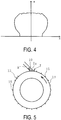
- a calculation is performed to convert the data illustrated in FIG. 3 to a tire outer surface position (coordinates at which an actual tire T is placed).
- data (X - Y coordinate data) illustrated in FIG. 4 is obtained.
- the trimming tool arm 9 (the trimming tool 6) is moved on the basis of the data illustrated in FIG. 4 .
- the unnecessary rubber components 15 and 16 are removed using the selected trimming tool 6 while the tire 12 is being rotated.
- the movement of the trimming tool arm 9 is controlled by the control unit 11 on the basis of the detection data detected by the profile sensor 4, and the selected trimming tool 6 and the tire 12 are moved relative to one another.
- the rotating tire 12 is fixed in a certain position, and thus, the trimming tool 6 is caused to move and the tip end section of the trimming tool 6 is positioned along the profile detected by the profile sensor 4.
- the cutter 7 when removing the spew 15 formed on the land portion 13, the cutter 7 is selected and held by the holding portion 9a, as illustrated in FIG. 5 .
- the thickness of the spew 15 has an outer diameter of 1 mm or greater and 2 mm or less, and a length of 5 mm or greater and 10 mm or less.
- the movement of the trimming tool arm 9 is controlled by the control unit 11 on the basis of the detection data detected by the profile sensor 4 (the data illustrated in FIG. 4 ).
- a cutter tip end section 7a of the selected cutter 7 is positioned along the profile (the shape illustrated in FIG. 4 ) detected by the profile sensor 4.
- the cutter tip end section 7a is positioned so as to extend along the direction of a tangent line of the tire outer surface, in a tire side view.
- the spew 15 is removed by the cutter 7.
- the cutter 7 being moved by the trimming tool arm 9 in the tire width direction along the profile detected by the profile sensor 4, all of the spew 15 formed on the land portion 13 is removed.
- the cutter 7 is moved by the trimming tool arm 9 on the basis of pressure data detected by the pressure sensor 10, and the pressure detected by the pressure sensor 10 is maintained within an allowable pressure range. Specifically, if this pressure is excessively large, unnecessary damage may be caused to the tire outer surface by the cutter 7. On the other hand, if this pressure is excessively small, insufficient removal may occur in which the spew 15 cannot be removed from the base. Further, the detection data detected by the profile sensor 4 (the data illustrated in FIG. 3 and FIG. 4 ) is average value data of the whole circumference in the tire circumferential direction. Thus, in the actual tire 12, due to the position in the tire circumferential direction, slight variations occur in the profile and the position thereof with respect to this detection data. Thus, the allowable pressure range is determined in advance, and the cutter 7 is moved so as to maintain this range.
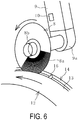
- the rotating brush 8 When removing the thin rubber film 16 formed on the groove portion 14, the rotating brush 8 is selected and held by the holding portion 9a, as illustrated in FIG. 6 .
- the thickness of the rubber film 16 is 1 mm or less (approximately 0.2 mm or greater and 0.8 mm or less), for example.
- the rotating brush 8 is configured by many non-metallic fiber-shaped bodies 8a detachably attached to a rotating spindle via a core 8b.
- the fiber-shaped bodies 8a extend radially from the core 8b in the radial direction, and the diameter thereof is set to less than 1 mm (0.3 mm or greater and 0.8 mm or less), for example. 6-6 nylon or 6-12 nylon based fibers are used as the fiber-shaped bodies 8a, for example. Note that, in FIG. 6 , the illustration omits some of the fiber-shaped bodies 8a.
- the movement of the trimming tool arm 9 is controlled by the control unit 11 on the basis of the detection data detected by the profile sensor 4 (the data illustrated in FIG. 4 ).
- the profile sensor 4 the data illustrated in FIG. 4
- tip end sections of the fiber-shaped bodies 8a of the selected rotating brush 8 are positioned along the profile (the shape illustrated in FIG. 4 ) detected by the profile sensor 4.
- the tip end sections of the fiber-shaped bodies 8a are positioned so as to come into contact with a bottom surface of the groove portion 14.
- the tip end sections of the plurality of fiber-shaped bodies 8a of the rotating brush 8 that is rotating come into contact with the whole section of the rubber film 16, and the rubber film 16 is instantly separated from both side surfaces and the bottom surface of the groove portion 14, and is cleanly removed.
- the rotation direction of the tire 12 and the rotation direction of the rotating brush 8 are set to be the same direction.
- a rate of rotation of the rotating brush 8 is approximately 10,000 rpm (8,000 rpm or greater and 12,000 rpm or less), for example.
- the rotating brush 8 may be moved on the basis of the pressure data detected by the pressure sensor 10, and the pressure detected by the pressure sensor 10 may be maintained within the allowable pressure range.
- Abrasive grains can also be mixed in with the fiber-shaped bodies 8a in advance.
- Aluminum oxide, silicon carbide and the like are used as the abrasive grains, for example, and the content by weight thereof is approximately 20% or greater and 40% or less. By mixing in the abrasive grains, the rubber film 16 is likely to be even more efficiently and cleanly removed.
- the profile of the tire width direction cross section of the tire outer surface and the position thereof are ascertained, and therefore, there is no need to prepare in advance profile data of the tire 12 to be trimmed and no need to perform an operation in advance to teach a control device the range over which trimming is to be performed.
- man-hours required for the trimming operation is reduced.
- this is advantageous to cleanly remove the unnecessary rubber components 15 and 16.
- the spew 15 and the rubber film 16 can each be cleanly removed.
- the profile and the position thereof are detected by the profile sensor 4 while rotating the tire 12, the profile alone is easily detected, without detecting the spew 15 and the rubber film 16 that are formed intermittently in the circumferential direction on the tire outer surface.
- the peripheral speed of the outer circumferential surface of the tire 12 at the time of the detection may be set to be a higher speed than the peripheral speed of the outer circumferential surface of the tire 12 when the unnecessary rubber components 15 and 16 are removed by the trimming tool 6.
- the peripheral speed of the outer circumferential surface of the tire 12 when detecting the profile is 200 mm/sec or greater and 4,000 mm/sec or less, for example, and the peripheral speed of the outer circumferential surface of the tire 12 when removing the unnecessary rubber components 15 and 16 is 30 mm/sec or greater and 2,000 mm/sec or less, for example.
- the spew 15 and the rubber film 16 can be cleanly removed without performing a complicated control procedure. According to the present invention, in this manner, in comparison to conventional techniques, the spew 15 and the rubber film 16 can be more efficiently and cleanly removed, without performing a complicated control procedure.
- the configuration is adopted in which the tire 12 is fixed in a predetermined position (the support body 2) and rotates, and at the same time, the trimming tool 6 is moved in the tire width direction and removes the spew 15 and the thin rubber film 16.
- the tire 12 and the trimming tool 6 move relative to one another.
- a configuration can be adopted in which the trimming tool 6 is fixed in a predetermined position, and the tire 12 is moved in the tire width direction while being rotated, thereby removing the spew 15 and the thin rubber film 16.
- the trimming tool 6 is fixed in the predetermined position of the support body 2, and the rotating shaft 3 to which the tire 12 is attached can be moved by the movement mechanism 9.
- the profile sensor 4 can also check whether the unnecessary rubber components 15 and 16 have been cleanly removed.
- the profile of the tire width direction cross section of the outer surface of the tire 12 after the removal process is detected while making the peripheral speed slower than the peripheral speed of the outer circumferential surface of the tire 12 when the profile is detected by the profile sensor 4 before the removal of the unnecessary rubber components 15 and 16.
- the peripheral speed of the outer circumferential surface of the tire 12 is slowed to a level at which the unnecessary rubber components 15 and 16 can be detected. Then, by comparing this detected data with the profile data (the data illustrated in FIG. 3 or FIG. 4 ) before the removal process, a state of removal of the unnecessary rubber components 15 and 16 can be verified.
Landscapes
- Engineering & Computer Science (AREA)
- Mechanical Engineering (AREA)
- Physics & Mathematics (AREA)
- Thermal Sciences (AREA)
- General Physics & Mathematics (AREA)
- Tyre Moulding (AREA)
- Length Measuring Devices With Unspecified Measuring Means (AREA)
Abstract
Description
- The present invention relates to a tire-trimming device and method, and more specifically, relates to a tire-trimming device and method which make it possible to more efficiently and cleanly remove unnecessary rubber components formed on a tire surface when vulcanizing the tire, without performing a complicated control procedure.
- When a tire is vulcanized, there are cases in which spew that is formed by the curing of unvulcanized rubber that has entered into a vent hole of a mold, or a thin rubber film that is formed by the curing of unvulcanized rubber that has overflowed from a joint of the mold are present on the tire surface. Conventionally, various trimming devices and methods have been proposed for cutting away spew on the tire surface (see
Patent Document 1, for example). - In a trimming method disclosed in
Patent Document 1, an image including a profile of a tread portion of the tire is captured from a tread side, and image data of the tire is acquired. The spew on the tire is identified on the basis of this image data, a blade tip of a spew cutter is positioned along a base of the spew, and the spew is cut off. In actuality, this trimming method substantially only targets and cuts off spew formed on a land portion of the tread, and uses one type of spew cutter for the trimming. - However, a form (the thickness, length, tilt, and shape) of the spew formed on the vulcanized tire is not uniform and differs depending on a portion of the tire surface. As a result, since a specification of an optimal cutter used to cut off the respective types of spew differs, it is difficult to cleanly cut off all of the spew with the one type of cutter. Further, a thin rubber film formed on a portion corresponding to a joint of a mold cannot be removed using the cutter used to cut off the spew formed on the land portion.
- Patent Document 1:
Japanese Unexamined Patent Application Publication No. H10-296877A - An object of the present invention is to provide a tire-trimming device and method capable of efficiently and cleanly removing unnecessary rubber components formed on a tire surface when vulcanizing the tire, without performing a complicated control procedure.
- In order to achieve the above object, a tire-trimming device of the present invention is provided with a rotation mechanism to rotate a tire and a trimming tool positioned on a tire outer surface of the tire. The tire-trimming device removes unnecessary rubber components formed on the tire outer surface when vulcanizing the tire, using the trimming tool while the tire is being rotated by the rotation mechanism, and includes: a plurality of different types of the trimming tool; a profile sensor detecting, while the tire is being rotated by the rotation mechanism, a profile of a tire width direction cross section of the tire outer surface and a position thereof; a control unit into which detection data detected by the profile sensor is input; and a movement mechanism causing the trimming tool and the tire to move relative to one another. The type of the trimming tool to be used according to a portion of the tire outer surface is set in advance in the control unit and when the unnecessary rubber components are removed, the type of the trimming tool set in advance for use on the portion on which the unnecessary rubber components are formed is selected, and, by a movement of the movement mechanism being controlled by the control unit on the basis of the detection data, a tip end section of the selected trimming tool is positioned along the profile detected by the profile sensor and removes the unnecessary rubber components.
- A tire-trimming method of the present invention removes unnecessary rubber components formed on a tire outer surface when vulcanizing the tire, using a trimming tool while rotating the tire. The tire-trimming method includes the steps of: detecting, using a profile sensor, a profile of a tire width direction cross section of a tire outer surface and a position thereof, while the tire is being rotated; inputting data detected by the profile sensor into a control unit; setting in advance, in the control unit, a type of the trimming tool to be used according to a portion of the tire outer surface; selecting, from among a plurality of different types of the trimming tool, the trimming tool set in advance to be used on the portion on which the unnecessary rubber components are formed, when removing the unnecessary rubber components; controlling a movement of a movement mechanism, using the control unit, on the basis of detection data detected by the profile sensor; moving the selected trimming tool and the tire relative to one another; positioning a tip end section of the selected trimming tool along the profile detected by the profile sensor; and removing the unnecessary rubber components.
- According to the present invention, a profile of a tire width direction cross section of a tire outer surface and a position thereof are detected using a profile sensor while rotating the tire, the trimming tool and the tire are moved relative to one another on the basis of data detected by the profile sensor, and a tip end section of the trimming tool is positioned along the profile detected by the profile sensor. Specifically, when trimming the tire, the profile of the tire width direction cross section of the tire outer surface and the position thereof are ascertained, and therefore, there is no need to prepare in advance profile data of the tire to be trimmed and no need to perform an operation in advance to teach a control device a range over which trimming is to be performed. Thus, man-hours required for the trimming operation can be reduced. Further, because the profile of each tire differs slightly, even with a tire of the same specification, detecting the profile and the position thereof of the tire to be trimmed is advantageous for cleanly removing unnecessary rubber components.
- In addition, a type of the trimming tool to be used according to a portion of the tire outer surface is set in advance in a control unit, and, when removing the unnecessary rubber components, the type of the trimming tool set in advance for use on the portion on which the unnecessary rubber components are formed is selected from among a plurality of the different types of the trimming tools, and is used. Thus, the optimum trimming tool for removing those unnecessary rubber components is used. This is thus even more advantageous for cleanly removing the respective unnecessary rubber components.
- Furthermore, because the profile and the position thereof are detected by the profile sensor while rotating the tire, the profile alone is easily detected, without detecting the unnecessary rubber components formed on the tire outer surface. Then, without identifying the location or the like of the unnecessary rubber components, the tip end section of the selected trimming tool is positioned along the detected profile, and the tire is rotated. As a result, the unnecessary rubber components can be cleanly removed without performing a complicated control procedure. In this way, as a result of achieving synergistic effects by combining all the above-described configurations, the present invention makes it possible to more efficiently and cleanly remove the unnecessary rubber components without performing a complicated control procedure, which is required conventionally.
-
- FIG. 1
- is an explanatory view illustrating a tire-trimming device of the present invention.
- FIG. 2
- is an explanatory view illustrating, in a cross-section view, a process of detecting a profile of a tire outer surface in a tire width direction.
- FIG. 3
- is an explanatory view illustrating detected profile data.
- FIG. 4
- is an explanatory view illustrating data obtained by converting the data in
FIG. 3 to a tire outer surface position. - FIG. 5
- is an explanatory view illustrating, in a tire side view, a process of removing spew formed on a land portion of the tire outer surface.
- FIG. 6
- is an explanatory view illustrating, in a perspective view, a process of removing a thin rubber film formed on a groove portion of the tire outer surface.
- FIG. 7
- is an explanatory view illustrating, in an enlarged tire side view, the process in
FIG. 6 . - A tire-trimming device and method of the present invention will be described below with reference to an embodiment illustrated in the drawings.
- A tire-
trimming device 1 of the present invention illustrated inFIG. 1 removes unnecessary rubber components formed on a tire outer surface when vulcanizing the tire. The unnecessary rubber components that are targeted for removal arespew 15 formed on aland portion 13, and athin rubber film 16 formed on agroove portion 14. - The tire-
trimming device 1 is provided with a rotating shaft 3 that is a rotation mechanism causing atire 12 to rotate, a trimming tool 6 positioned on the tire outer surface of thetire 12, aprofile sensor 4, acontrol unit 11 into which detection data detected by theprofile sensor 4 is input, and amovement mechanism 9 that moves the trimming tool 6 and thetire 12 relative to one another. In the present embodiment, themovement mechanism 9 is formed by atrimming tool arm 9 that moves freely in three dimensions. For example, an arm of an industrial robot can be used as themovement mechanism 9. Movement of thetrimming tool arm 9 is controlled by thecontrol unit 11. - The rotating shaft 3 extends in the horizontal direction from a
support body 2 provided standing on the ground. Thetire 12 is, for example, assembled on a rim, and is attached to the rotating shaft 3 by this rim being fixed to the rotating shaft 3. The rotating shaft 3 is configured such that it can be adjusted to a given rotation speed by thecontrol unit 11. The rotation speed is, for example, a peripheral speed of the outer circumferential surface of thetire 12 that is 30 mm/sec or greater and 4,000 mm/sec or less. - The
profile sensor 4 detects a profile of a tire width direction cross section of the tire outer surface, and a position thereof. An optical sensor used for optical cutting measurement or image processing is used as theprofile sensor 4, for example. In the present embodiment, theprofile sensor 4 is attached to a second end of asensor arm 5, whose first end is rotatably attached to thesupport body 2. - A
holding portion 9a, which holds the trimming tool 6, is provided on a tip end section of thetrimming tool arm 9. Further, apressure sensor 10 is provided on thetrimming tool arm 9. Thepressure sensor 10 successively detects a pressure with which the trimming tool 6 presses the tire outer surface. Data detected by thepressure sensor 10 is input into thecontrol unit 11. - The
trimming device 1 has a plurality of different types of the trimming tool 6. In the present embodiment, thetrimming device 1 has two types of the trimming tool 6, namely, acutter 7 and arotating brush 8. The trimming tool 6 is not limited to the two types and can be three types or more. Further, a plurality of types of the trimming tool 6 can be created by causing the blade length and the blade bending rigidity of thecutter 7 to be different. Of the plurality of types of the trimming tool 6, one trimming tool 6 is selected and held by the holdingportion 9a of thetrimming tool arm 9. - The type of the trimming tool 6 to be used in accordance with a portion of the tire outer surface is input and set in the
control unit 11 in advance. For example, thecutter 7 adopted as the trimming tool 6 used for theland portion 13 of the tire outer surface, and therotating brush 8 adopted as the trimming tool 6 used for thegroove portion 14 are each set in thecontrol unit 11 in advance. - Next, an example will be described of a procedure of a tire-trimming method of the present invention.
- First, the profile of the
tire 12 to be trimmed is ascertained. Here, while rotating thetire 12 by driving the rotating shaft 3 to rotate, the profile of the tire width direction cross section of the tire outer surface and the position thereof are detected by theprofile sensor 4. Specifically, as illustrated inFIG. 2 , theprofile sensor 4 is moved in the tire width direction along the outer surface of therotating tire 12, by a constant radius R around a center CP as the center of rotation of thetire 12. - In this process, a rotation angle θ of the
profile sensor 4 that is caused to move and a distance α from theprofile sensor 4 to the tire outer surface are detected. As a result of this process, data illustrated inFIG. 3 (θ-α coordinate data) is acquired, and this detection data is input into thecontrol unit 11. - In the
control unit 11, a calculation is performed to convert the data illustrated inFIG. 3 to a tire outer surface position (coordinates at which an actual tire T is placed). As a result of this calculation, data (X - Y coordinate data) illustrated inFIG. 4 is obtained. When removing theunnecessary rubber components FIG. 4 . - The
unnecessary rubber components tire 12 is being rotated. The movement of thetrimming tool arm 9 is controlled by thecontrol unit 11 on the basis of the detection data detected by theprofile sensor 4, and the selected trimming tool 6 and thetire 12 are moved relative to one another. In the present embodiment, the rotatingtire 12 is fixed in a certain position, and thus, the trimming tool 6 is caused to move and the tip end section of the trimming tool 6 is positioned along the profile detected by theprofile sensor 4. - For example, when removing the spew 15 formed on the
land portion 13, thecutter 7 is selected and held by the holdingportion 9a, as illustrated inFIG. 5 . The thickness of the spew 15 has an outer diameter of 1 mm or greater and 2 mm or less, and a length of 5 mm or greater and 10 mm or less. Then, the movement of thetrimming tool arm 9 is controlled by thecontrol unit 11 on the basis of the detection data detected by the profile sensor 4 (the data illustrated inFIG. 4 ). In this way, a cutter tip end section 7a of the selectedcutter 7 is positioned along the profile (the shape illustrated inFIG. 4 ) detected by theprofile sensor 4. Specifically, the cutter tip end section 7a is positioned so as to extend along the direction of a tangent line of the tire outer surface, in a tire side view. - Since the
tire 12 is rotating, the spew 15 is removed by thecutter 7. As a result of thecutter 7 being moved by thetrimming tool arm 9 in the tire width direction along the profile detected by theprofile sensor 4, all of the spew 15 formed on theland portion 13 is removed. - In the present embodiment, the
cutter 7 is moved by thetrimming tool arm 9 on the basis of pressure data detected by thepressure sensor 10, and the pressure detected by thepressure sensor 10 is maintained within an allowable pressure range. Specifically, if this pressure is excessively large, unnecessary damage may be caused to the tire outer surface by thecutter 7. On the other hand, if this pressure is excessively small, insufficient removal may occur in which the spew 15 cannot be removed from the base. Further, the detection data detected by the profile sensor 4 (the data illustrated inFIG. 3 andFIG. 4 ) is average value data of the whole circumference in the tire circumferential direction. Thus, in theactual tire 12, due to the position in the tire circumferential direction, slight variations occur in the profile and the position thereof with respect to this detection data. Thus, the allowable pressure range is determined in advance, and thecutter 7 is moved so as to maintain this range. - When removing the
thin rubber film 16 formed on thegroove portion 14, the rotatingbrush 8 is selected and held by the holdingportion 9a, as illustrated inFIG. 6 . The thickness of therubber film 16 is 1 mm or less (approximately 0.2 mm or greater and 0.8 mm or less), for example. Therotating brush 8 is configured by many non-metallic fiber-shapedbodies 8a detachably attached to a rotating spindle via acore 8b. The fiber-shapedbodies 8a extend radially from thecore 8b in the radial direction, and the diameter thereof is set to less than 1 mm (0.3 mm or greater and 0.8 mm or less), for example. 6-6 nylon or 6-12 nylon based fibers are used as the fiber-shapedbodies 8a, for example. Note that, inFIG. 6 , the illustration omits some of the fiber-shapedbodies 8a. - Then, the movement of the
trimming tool arm 9 is controlled by thecontrol unit 11 on the basis of the detection data detected by the profile sensor 4 (the data illustrated inFIG. 4 ). In this way, tip end sections of the fiber-shapedbodies 8a of the selected rotatingbrush 8 are positioned along the profile (the shape illustrated inFIG. 4 ) detected by theprofile sensor 4. Specifically, as illustrated inFIG. 7 , the tip end sections of the fiber-shapedbodies 8a are positioned so as to come into contact with a bottom surface of thegroove portion 14. - In this way, in the
groove portion 14, the tip end sections of the plurality of fiber-shapedbodies 8a of therotating brush 8 that is rotating come into contact with the whole section of therubber film 16, and therubber film 16 is instantly separated from both side surfaces and the bottom surface of thegroove portion 14, and is cleanly removed. The rotation direction of thetire 12 and the rotation direction of therotating brush 8 are set to be the same direction. A rate of rotation of therotating brush 8 is approximately 10,000 rpm (8,000 rpm or greater and 12,000 rpm or less), for example. - Because the
tire 12 is rotating, therubber film 16 formed on thegroove portion 14 extending in the circumferential direction is successively removed in a similar manner. In this case also, the rotatingbrush 8 may be moved on the basis of the pressure data detected by thepressure sensor 10, and the pressure detected by thepressure sensor 10 may be maintained within the allowable pressure range. - Abrasive grains can also be mixed in with the fiber-shaped
bodies 8a in advance. Aluminum oxide, silicon carbide and the like are used as the abrasive grains, for example, and the content by weight thereof is approximately 20% or greater and 40% or less. By mixing in the abrasive grains, therubber film 16 is likely to be even more efficiently and cleanly removed. - According to the present invention, as described above, when trimming the
tire 12, the profile of the tire width direction cross section of the tire outer surface and the position thereof are ascertained, and therefore, there is no need to prepare in advance profile data of thetire 12 to be trimmed and no need to perform an operation in advance to teach a control device the range over which trimming is to be performed. Thus, man-hours required for the trimming operation is reduced. Further, because the unique profile and the position thereof of each tire to be trimmed are detected, this is advantageous to cleanly remove theunnecessary rubber components - In addition, because the type of the trimming tool 6 appropriate to be used for each portion of the tire outer surface is set in advance in the
control unit 11, the spew 15 and therubber film 16 can each be cleanly removed. - Furthermore, because the profile and the position thereof are detected by the
profile sensor 4 while rotating thetire 12, the profile alone is easily detected, without detecting the spew 15 and therubber film 16 that are formed intermittently in the circumferential direction on the tire outer surface. - When the
profile sensor 4 detects the profile of the tire width direction cross section of the tire outer surface and the position thereof, if the rotation speed (the peripheral speed of the outer circumferential surface) of thetire 12 is accelerated, theunnecessary rubber components unnecessary rubber components tire 12 at the time of the detection may be set to be a higher speed than the peripheral speed of the outer circumferential surface of thetire 12 when theunnecessary rubber components tire 12 when detecting the profile is 200 mm/sec or greater and 4,000 mm/sec or less, for example, and the peripheral speed of the outer circumferential surface of thetire 12 when removing theunnecessary rubber components - Further, because the
tire 12 is rotated while the tip end section of the selected trimming tool 6 is positioned along the detected profile, without identifying the locations at which the spew 15 and therubber film 16 exist and the like, the spew 15 and therubber film 16 can be cleanly removed without performing a complicated control procedure. According to the present invention, in this manner, in comparison to conventional techniques, the spew 15 and therubber film 16 can be more efficiently and cleanly removed, without performing a complicated control procedure. - In the above-described embodiment, the configuration is adopted in which the
tire 12 is fixed in a predetermined position (the support body 2) and rotates, and at the same time, the trimming tool 6 is moved in the tire width direction and removes the spew 15 and thethin rubber film 16. However, it is sufficient that thetire 12 and the trimming tool 6 move relative to one another. Specifically, a configuration can be adopted in which the trimming tool 6 is fixed in a predetermined position, and thetire 12 is moved in the tire width direction while being rotated, thereby removing the spew 15 and thethin rubber film 16. For example, the trimming tool 6 is fixed in the predetermined position of thesupport body 2, and the rotating shaft 3 to which thetire 12 is attached can be moved by themovement mechanism 9. - After the process to remove the
unnecessary rubber components profile sensor 4 can also check whether theunnecessary rubber components tire 12 after the removal process is detected while making the peripheral speed slower than the peripheral speed of the outer circumferential surface of thetire 12 when the profile is detected by theprofile sensor 4 before the removal of theunnecessary rubber components tire 12 is slowed to a level at which theunnecessary rubber components FIG. 3 orFIG. 4 ) before the removal process, a state of removal of theunnecessary rubber components -
- 1
- Trimming device
- 2
- Support body
- 3
- Rotating shaft
- 4
- Profile sensor
- 5
- Sensor arm
- 6
- Trimming tool
- 7
- Cutter
- 7a
- Cutter tip end section
- 8
- Rotating brush
- 8a
- Fiber-shaped bodies
- 9
- Trimming tool arm (movement mechanism)
- 9a
- Holding portion
- 10
- Pressure sensor
- 11
- Control unit
- 12
- Tire
- 13
- Land portion
- 14
- Groove portion
- 15
- Spew (unnecessary rubber component)
- 16
- Thin rubber film (unnecessary rubber component)
Claims (12)
- A tire-trimming device provided with a rotation mechanism to rotate a tire and a trimming tool positioned on a tire outer surface of the tire, for removing, using the trimming tool while the tire is being rotated by the rotation mechanism, unnecessary rubber components formed on the tire outer surface when vulcanizing the tire, the tire-trimming tool comprising:a plurality of different types of the trimming tool; a profile sensor detecting, while the tire is being rotated by the rotation mechanism, a profile of a tire width direction cross section of the tire outer surface and a position thereof; a control unit into which detection data detected by the profile sensor is input; and a movement mechanism causing the trimming tool and the tire to move relative to one another, wherein the type of the trimming tool to be used according to a portion of the tire outer surface is set in advance in the control unit and when the unnecessary rubber components are removed, the type of the trimming tool set in advance for use on the portion on which the unnecessary rubber components are formed is selected, and, by a movement of the movement mechanism being controlled by the control unit on the basis of the detection data, a tip end section of the selected trimming tool is positioned along the profile detected by the profile sensor and removes the unnecessary rubber components.
- The tire-trimming device according to claim 1, wherein
a cutter is set in advance as the trimming tool to be used on a land portion of the tire outer surface, and a rotating brush is set in advance as the trimming tool to be used on a groove portion of the tire outer surface. - The tire-trimming device according to claim 1 or 2, wherein
a peripheral speed of the tire outer surface when detecting the profile and the position thereof using the profile sensor is set to be a higher speed than a peripheral speed of the tire outer surface when removing the unnecessary rubber components using the selected trimming tool. - The tire-trimming device according to any one of claims 1 to 3, further comprising:a pressure sensor successively detecting a pressure with which the selected trimming tool presses the tire outer surface, wherein pressure data detected by the pressure sensor is input into the control unit, the selected trimming tool and the tire are caused to move relative to one another by the movement mechanism on the basis of the pressure data detected by the pressure sensor, and the pressure detected by the pressure sensor is maintained within an allowable pressure range.
- The tire-trimming device according to any one of claims 1 to 4, wherein
as well as the tire rotating while being fixed in a predetermined position, the selected trimming tool removes the unnecessary rubber components while being moved in a tire width direction. - The tire-trimming device according to any one of claims 1 to 4, wherein
as well as the selected trimming tool being fixed in a predetermined position, the tire is moved in a tire width direction while being rotated, and the unnecessary rubber components are removed. - A tire-trimming method for removing unnecessary rubber components formed on a tire outer surface when vulcanizing the tire, using a trimming tool while rotating the tire, the tire-trimming method comprising the steps of:detecting, using a profile sensor, a profile of a tire width direction cross section of the tire outer surface and a position thereof, while the tire is being rotated; inputting data detected by the profile sensor into a control unit; setting in advance, in the control unit, a type of the trimming tool to be used according to a portion of the tire outer surface; selecting, from among a plurality of different types of the trimming tool, the trimming tool set in advance to be used on the portion on which the unnecessary rubber components are formed, when removing the unnecessary rubber components; controlling a movement of a movement mechanism, using the control unit, on the basis of detection data detected by the profile sensor; moving the selected trimming tool and the tire relative to one another; positioning a tip end section of the selected trimming tool along the profile detected by the profile sensor; and removing the unnecessary rubber components.
- The tire-trimming method according to claim 7, wherein
a cutter is set in advance as the trimming tool to be used on a land portion of the tire outer surface, and a rotating brush is set in advance as the trimming tool to be used on a groove portion of the tire outer surface. - The tire-trimming method according to claim 7 or 8, wherein
a peripheral speed of the tire outer surface when detecting the profile and the position thereof using the profile sensor is set to be higher than a peripheral speed of the tire outer surface when removing the unnecessary rubber components using the selected trimming tool. - The tire-trimming method according to any one of claims 7 to 9, further comprising:successively detecting a pressure, using a pressure sensor, with which the selected trimming tool presses the tire outer surface, wherein the selected trimming tool and the tire are caused to move relative to one another by controlling the movement of the movement mechanism, using the control unit, on the basis of pressure data detected by the pressure sensor, and the pressure detected by the pressure sensor is maintained within an allowable pressure range.
- The tire-trimming method according to any one of claims 7 to 10, wherein as well as the tire being fixed in a predetermined position and being rotated, the selected trimming tool removes the unnecessary rubber components while being moved in a tire width direction.
- The tire-trimming method according to any one of claims 7 to 10, wherein as well as the selected trimming tool being fixed in a predetermined position, the tire is moved in a tire width direction while being rotated, and the unnecessary rubber components are removed.
Applications Claiming Priority (2)
| Application Number | Priority Date | Filing Date | Title |
|---|---|---|---|
| JP2014097994A JP5831592B2 (en) | 2014-05-09 | 2014-05-09 | Tire trimming apparatus and method |
| PCT/JP2015/063334 WO2015170749A1 (en) | 2014-05-09 | 2015-05-08 | Tire-trimming device and method |
Publications (2)
| Publication Number | Publication Date |
|---|---|
| EP3141383A1 true EP3141383A1 (en) | 2017-03-15 |
| EP3141383A4 EP3141383A4 (en) | 2018-01-10 |
Family
ID=54392597
Family Applications (1)
| Application Number | Title | Priority Date | Filing Date |
|---|---|---|---|
| EP15788705.0A Withdrawn EP3141383A4 (en) | 2014-05-09 | 2015-05-08 | Tire-trimming device and method |
Country Status (5)
| Country | Link |
|---|---|
| US (1) | US11878482B2 (en) |
| EP (1) | EP3141383A4 (en) |
| JP (1) | JP5831592B2 (en) |
| CN (1) | CN106457718B (en) |
| WO (1) | WO2015170749A1 (en) |
Families Citing this family (7)
| Publication number | Priority date | Publication date | Assignee | Title |
|---|---|---|---|---|
| US9833931B2 (en) * | 2016-02-10 | 2017-12-05 | Akron Special Machinery, Inc. | Method and apparatus for removing flash from a tire |
| CN109909674B (en) * | 2019-04-29 | 2023-11-07 | 中信戴卡股份有限公司 | Wheel rim finishing device and rim finishing method |
| CN110936532B (en) * | 2019-12-18 | 2024-12-31 | 杭州言志机械制造有限公司 | Automatic tire scraping device |
| CN115401835B (en) * | 2022-06-27 | 2025-04-25 | 大陆马牌轮胎(中国)有限公司 | A tire repair device with a driving device inside |
| CN115257038A (en) * | 2022-09-03 | 2022-11-01 | 平湖市创新高分子材料股份有限公司 | Child car tire forming equipment and process |
| DE102024205577A1 (en) * | 2024-06-17 | 2025-12-18 | Continental Reifen Deutschland Gmbh | Tire blank deburring device, preferably a robot for deburring a tire blank |
| CN120245285A (en) * | 2025-06-06 | 2025-07-04 | 山东诚汇金实业有限公司 | A production and processing device for polyester tires |
Family Cites Families (29)
| Publication number | Priority date | Publication date | Assignee | Title |
|---|---|---|---|---|
| GB663495A (en) * | 1948-11-06 | 1951-12-19 | Vaughn Rawls | Tyre lug buffer |
| US2707851A (en) * | 1953-10-01 | 1955-05-10 | Goodrich Co B F | Tire sidewall finishing machine and method |
| US2986849A (en) * | 1957-11-12 | 1961-06-06 | Goodyear Tire & Rubber | Tire sidewall finishing machine and method |
| US4059139A (en) * | 1975-04-04 | 1977-11-22 | Bridgestone Tire Company Limited | Tire finishing apparatus |
| US4759638A (en) * | 1987-02-25 | 1988-07-26 | Mclaughlin Hugh Rogers | Wheel with pivotable ground pads |
| JPH01163052A (en) * | 1987-12-19 | 1989-06-27 | Sumitomo Rubber Ind Ltd | Cutter support device of grooving apparatus |
| AU606487B2 (en) * | 1987-12-19 | 1991-02-07 | Sumitomo Rubber Industries, Ltd. | Method for correcting tyre deflection in tyre grooving and apparatus therefor |
| JPH0726908B2 (en) * | 1988-01-25 | 1995-03-29 | 三菱電機株式会社 | Coating film adhesion strength or shear strength measuring device |
| US5193600A (en) * | 1988-07-28 | 1993-03-16 | Sumitomo Rubber Industries, Ltd. | Tire grooving apparatus and method |
| JPH05215530A (en) * | 1992-02-06 | 1993-08-24 | Kobe Steel Ltd | Outer-shape measuring apparatus for body such as tire |
| JPH10296877A (en) | 1997-04-22 | 1998-11-10 | Sumitomo Rubber Ind Ltd | Tire trimming device and trimming method |
| JPH10315348A (en) * | 1997-05-19 | 1998-12-02 | Sumitomo Rubber Ind Ltd | Tire trimming device and trimming method |
| US5974643A (en) * | 1998-06-25 | 1999-11-02 | General Motors Corporation | Programmable vision-guided robotic turret-mounted tools |
| JP4194198B2 (en) * | 1999-11-29 | 2008-12-10 | 横浜ゴム株式会社 | Method and apparatus for automatically trimming tire spew |
| JP4726286B2 (en) * | 2000-09-07 | 2011-07-20 | 株式会社ブリヂストン | Raw tire excavation groove forming method and apparatus |
| JP3658685B2 (en) * | 2001-05-28 | 2005-06-08 | 株式会社アルティア橋本 | Subject distance measuring device |
| US20040074292A1 (en) * | 2002-10-03 | 2004-04-22 | Irwin Robert Dean | Cutter assembly for correcting tire nonuniformity |
| JP4205467B2 (en) * | 2003-03-31 | 2009-01-07 | 横浜ゴム株式会社 | Profile measuring apparatus and profile measuring method |
| JP4452691B2 (en) * | 2005-08-04 | 2010-04-21 | リンテック株式会社 | Sheet cutting device and cutting method |
| JP4571572B2 (en) * | 2005-10-18 | 2010-10-27 | 株式会社ブリヂストン | Tire grinding method and grinding apparatus |
| US8056202B2 (en) * | 2006-04-27 | 2011-11-15 | Bridgestone Americas Tire Operations, Llc | Tire replacement system for compact tractor |
| JP2008126479A (en) * | 2006-11-20 | 2008-06-05 | Bridgestone Corp | Method for removing buffing dust from tire casing |
| JP5046688B2 (en) | 2007-03-08 | 2012-10-10 | 株式会社神戸製鋼所 | Tire shape detection device and tire shape detection method |
| JP2010042536A (en) * | 2008-08-11 | 2010-02-25 | Bridgestone Corp | Method for manufacturing regenerated tire and grinder for used tire |
| US7779943B2 (en) * | 2008-10-08 | 2010-08-24 | Bosye, Llc | Hybrid-powered slow-speed vehicle, vehicle travel-range extension method, and method of hybrid-vehicle manufacture |
| US8585843B2 (en) * | 2010-03-08 | 2013-11-19 | Bridgestone Bandag, Llc | Tire tread buffing apparatus and method |
| JP5726045B2 (en) * | 2011-11-07 | 2015-05-27 | 株式会社神戸製鋼所 | Tire shape inspection method and tire shape inspection device |
| JP5632872B2 (en) * | 2012-04-02 | 2014-11-26 | 住友ゴム工業株式会社 | Ring tread buffing device for retreaded tires |
| FR2991234B1 (en) * | 2012-05-31 | 2015-04-03 | Michelin & Cie | METHOD FOR MANUFACTURING A FLEXIBLE WALL IN A PNEUMATIC BEARING TRAP |
-
2014
- 2014-05-09 JP JP2014097994A patent/JP5831592B2/en active Active
-
2015
- 2015-05-08 US US15/310,092 patent/US11878482B2/en active Active
- 2015-05-08 WO PCT/JP2015/063334 patent/WO2015170749A1/en not_active Ceased
- 2015-05-08 CN CN201580023899.1A patent/CN106457718B/en active Active
- 2015-05-08 EP EP15788705.0A patent/EP3141383A4/en not_active Withdrawn
Also Published As
| Publication number | Publication date |
|---|---|
| CN106457718B (en) | 2019-02-05 |
| EP3141383A4 (en) | 2018-01-10 |
| US20170266903A1 (en) | 2017-09-21 |
| US11878482B2 (en) | 2024-01-23 |
| CN106457718A (en) | 2017-02-22 |
| WO2015170749A1 (en) | 2015-11-12 |
| JP5831592B2 (en) | 2015-12-09 |
| JP2015214077A (en) | 2015-12-03 |
Similar Documents
| Publication | Publication Date | Title |
|---|---|---|
| US11878482B2 (en) | Tire-trimming device and method | |
| US10478935B2 (en) | Deburring apparatus | |
| US12325105B2 (en) | Systems and methods for conditioning blades | |
| JP5883016B2 (en) | Method for machining the casing of an aircraft turboshaft engine and scraper tool for carrying out said method | |
| ITMI20090505A1 (en) | PROCEDURE AND MACHINE FOR THE IDENTIFICATION AND PROCESSING OF DEFECTS ON USED TIRES. | |
| EP2777851B1 (en) | Aircraft skin surface planing apparatus and method | |
| EP2623261A3 (en) | Eyeglass lens processing apparatus | |
| JP2012076173A5 (en) | ||
| WO2012073374A1 (en) | Method for deburring end face of formed groove, and formed rotary cutting tool for chamfering | |
| CN101443155A (en) | Method and device for trimming a lens by cutting said lens | |
| JP2008128790A (en) | Damage detection method, tire regeneration method and tire regeneration device | |
| CA2583085A1 (en) | Aging apparatus for aging an artificial stone | |
| CN107949448A (en) | Method for manufacture machine component, the equipment for manufacture machine component, the method for processing rotationally symmetrical surf, recording medium and program | |
| EP3201363A1 (en) | Apparatus and method for sharpening the scraping edges of a scraper roller | |
| KR101610000B1 (en) | Method for processing eyeglass lens | |
| JP6237167B2 (en) | Apparatus and method for cutting rubber-coated fiber sheet member | |
| JP6034667B2 (en) | Tire trimming device | |
| JP4733791B2 (en) | Deburring device | |
| CN207577431U (en) | A kind of processing bearing race internal diameter and chamfering Integral molding device for insoles | |
| US10386812B2 (en) | Apparatus, methods, computer programs and non-transitory computer readable storage mediums for machining objects | |
| JP6615434B2 (en) | Unvulcanized rubber sheet punching apparatus and method | |
| JP2012201001A (en) | Tire trimming method and tire trimming device | |
| RU2311991C2 (en) | Method for high-accuracy free-rolling around working of spherical surface | |
| CN103878813A (en) | Device for peeling O-shaped rings from valve bodies | |
| WO2014193231A1 (en) | Profile cutting tool for non-round profiles |
Legal Events
| Date | Code | Title | Description |
|---|---|---|---|
| STAA | Information on the status of an ep patent application or granted ep patent |
Free format text: STATUS: THE INTERNATIONAL PUBLICATION HAS BEEN MADE |
|
| PUAI | Public reference made under article 153(3) epc to a published international application that has entered the european phase |
Free format text: ORIGINAL CODE: 0009012 |
|
| STAA | Information on the status of an ep patent application or granted ep patent |
Free format text: STATUS: REQUEST FOR EXAMINATION WAS MADE |
|
| 17P | Request for examination filed |
Effective date: 20161207 |
|
| AK | Designated contracting states |
Kind code of ref document: A1 Designated state(s): AL AT BE BG CH CY CZ DE DK EE ES FI FR GB GR HR HU IE IS IT LI LT LU LV MC MK MT NL NO PL PT RO RS SE SI SK SM TR |
|
| AX | Request for extension of the european patent |
Extension state: BA ME |
|
| DAV | Request for validation of the european patent (deleted) | ||
| DAX | Request for extension of the european patent (deleted) | ||
| A4 | Supplementary search report drawn up and despatched |
Effective date: 20171207 |
|
| RIC1 | Information provided on ipc code assigned before grant |
Ipc: B29C 37/02 20060101ALI20171201BHEP Ipc: B29D 30/68 20060101AFI20171201BHEP Ipc: G01B 21/20 20060101ALI20171201BHEP |
|
| STAA | Information on the status of an ep patent application or granted ep patent |
Free format text: STATUS: THE APPLICATION IS DEEMED TO BE WITHDRAWN |
|
| 18D | Application deemed to be withdrawn |
Effective date: 20180714 |