EP3141165A1 - Pack feeding/detaching mechanism for beverage brewing device - Google Patents
Pack feeding/detaching mechanism for beverage brewing device Download PDFInfo
- Publication number
- EP3141165A1 EP3141165A1 EP14891489.8A EP14891489A EP3141165A1 EP 3141165 A1 EP3141165 A1 EP 3141165A1 EP 14891489 A EP14891489 A EP 14891489A EP 3141165 A1 EP3141165 A1 EP 3141165A1
- Authority
- EP
- European Patent Office
- Prior art keywords
- frame
- capsule
- guiding
- jaw
- rear end
- Prior art date
- Legal status (The legal status is an assumption and is not a legal conclusion. Google has not performed a legal analysis and makes no representation as to the accuracy of the status listed.)
- Granted
Links
- 230000007246 mechanism Effects 0.000 title claims abstract description 59
- 235000013361 beverage Nutrition 0.000 title claims abstract description 16
- 239000002775 capsule Substances 0.000 claims abstract description 108
- 238000000605 extraction Methods 0.000 description 9
- 238000000034 method Methods 0.000 description 8
- 230000008569 process Effects 0.000 description 8
- 230000009471 action Effects 0.000 description 3
- 230000005484 gravity Effects 0.000 description 2
- 239000007788 liquid Substances 0.000 description 2
- 230000004888 barrier function Effects 0.000 description 1
- 238000010586 diagram Methods 0.000 description 1
- 238000004519 manufacturing process Methods 0.000 description 1
- 238000002360 preparation method Methods 0.000 description 1
Images


Classifications
-
- A—HUMAN NECESSITIES
- A47—FURNITURE; DOMESTIC ARTICLES OR APPLIANCES; COFFEE MILLS; SPICE MILLS; SUCTION CLEANERS IN GENERAL
- A47J—KITCHEN EQUIPMENT; COFFEE MILLS; SPICE MILLS; APPARATUS FOR MAKING BEVERAGES
- A47J31/00—Apparatus for making beverages
- A47J31/24—Coffee-making apparatus in which hot water is passed through the filter under pressure, i.e. in which the coffee grounds are extracted under pressure
- A47J31/34—Coffee-making apparatus in which hot water is passed through the filter under pressure, i.e. in which the coffee grounds are extracted under pressure with hot water under liquid pressure
- A47J31/36—Coffee-making apparatus in which hot water is passed through the filter under pressure, i.e. in which the coffee grounds are extracted under pressure with hot water under liquid pressure with mechanical pressure-producing means
- A47J31/3604—Coffee-making apparatus in which hot water is passed through the filter under pressure, i.e. in which the coffee grounds are extracted under pressure with hot water under liquid pressure with mechanical pressure-producing means with a mechanism arranged to move the brewing chamber between loading, infusing and ejecting stations
- A47J31/3623—Cartridges being employed
- A47J31/3638—Means to eject the cartridge after brewing
-
- A—HUMAN NECESSITIES
- A47—FURNITURE; DOMESTIC ARTICLES OR APPLIANCES; COFFEE MILLS; SPICE MILLS; SUCTION CLEANERS IN GENERAL
- A47J—KITCHEN EQUIPMENT; COFFEE MILLS; SPICE MILLS; APPARATUS FOR MAKING BEVERAGES
- A47J31/00—Apparatus for making beverages
- A47J31/24—Coffee-making apparatus in which hot water is passed through the filter under pressure, i.e. in which the coffee grounds are extracted under pressure
- A47J31/34—Coffee-making apparatus in which hot water is passed through the filter under pressure, i.e. in which the coffee grounds are extracted under pressure with hot water under liquid pressure
- A47J31/36—Coffee-making apparatus in which hot water is passed through the filter under pressure, i.e. in which the coffee grounds are extracted under pressure with hot water under liquid pressure with mechanical pressure-producing means
- A47J31/3604—Coffee-making apparatus in which hot water is passed through the filter under pressure, i.e. in which the coffee grounds are extracted under pressure with hot water under liquid pressure with mechanical pressure-producing means with a mechanism arranged to move the brewing chamber between loading, infusing and ejecting stations
- A47J31/3623—Cartridges being employed
- A47J31/3633—Means to perform transfer from a loading position to an infusing position
Definitions
- the present invention relates to a capsules delivery and rejection mechanism in a beverage extraction device, and the beverage extraction device mainly refers to a coffeemaker.
- the existing coffeemaker generally has a function of automatic capsule rejection for ease of operation.
- a Chinese Utility Model Patent CN201044719Y Patent No.: 200720110811.2
- titled “Capsule Automatically Rejecting Mechanism of Coffeemaker” disclosed a coffeemaker which has a simple and rational structure, is stable and convenient in operation and feels good in touching is invented.
- a spring is provided inside the chamber of the first frame. The forgoing coffeemaker structure is somewhat improved.
- a capsule dropping mechanism comprising: a housing; a first frame having a chamber for holding a capsule with a circular edge; a second frame; two jaws, characterized in that notches for receiving clamp portions are formed on left and right sides of a rear end surface of the first frame; two groups of guiding grooves for guiding a front shaft and a rear shaft of the jaws are provided on the housing; in a state in which the first frame and the second frame are totally closed, the clamp portions on the two jaws are located within the notch of the first frame; and in a state in which the second frame moves backward, the limiting portions on the two jaws move backward along with the second frame and come into contact with the circular edge of the capsule to drive the capsule to move backward and out of the chamber.
- the driving of the clamp portions can push the capsule from the chamber of the
- two groups guiding grooves for guiding the front shaft and the rear shaft of the jaws are provided on the housing, the jaws move forward along with the second frame during the whole capsule delivery process, and there is no idle stroke between the jaws and the second frame. Therefore, in order to completely deliver a capsule into the chamber and the guiding grooves can guide the jaws to open and close according to the requirement of capsule dropping, it is necessary to provide a large overall length for the guiding grooves.
- the guiding grooves include a straight rear groove, a straight front groove, a curved middle groove and a curved front groove, the straight front groove is in front of the straight rear groove and inclined outward, the curved middle groove is on the outer side of the straight rear groove, and the curved front groove and the straight front groove are separated by a second barrier. Accordingly, in the foregoing two patents, the overall length of the guiding grooves is large, and the working process of the coffeemaker is completed. Consequently, the length of the whole housing cannot be made small and the coffeemaker cannot be miniaturized.
- a technical problem to be solved by the present invention is to provide a novel capsule delivery and rejection mechanism for a beverage brewing device, which has a simpler and more rational structure and allows for reliable capsule delivery and rejection.
- the mechanism has a smaller overall size and is low in cost and easy to assemble.
- the capsule delivery and rejection mechanism for a beverage brewing device comprises: a housing having a front portion, a back portion, a loading port, and a dropping port; a first frame positioned inside the front portion of the housing, the first frame having a left side, a right side, a chamber for holding a capsule with a circular edge; a second frame having a left side and a right side, disposed inside the back portion of the housing and being movable forward and backward relative to the first frame; characterized in that, the capsule delivery and rejection mechanism further comprises: two jaws, each jaw having a front end and a rear end, the rear end of each jaw respectively rotatably connected to the left and right sides of the second frame, the front end of each jaw being a clamp portion extending to the front of the second frame, the clamp portion having a clamping opening capable of clamping the circular edge of the capsule; two guiding blocks, each guiding block being rotatably arranged at front of each jaw and are able to be deflected, each
- an elastic mechanism for enabling the jaws to keep an inward clamping trend is provided on the second frame.
- the elastic mechanism enables the jaws to keep a clamping trend so as to make the jaws clamp the beverage capsule better, or to make the jaws to return to the original positions during the backward movement process so as to drive the beverage capsule.
- the functions of the elastic mechanism can be realized by a similar guide structure.
- the elastic mechanism is a torsion spring provided on a spindle at the rear end of the jaws.
- the torsion spring is easy to assemble.
- other elastic members such as a spring, can also be used.
- the capsule delivery and rejection mechanism characterized in that, a recess for receiving each jaw is respectively provided on the left and right sidewalls of the second frame, and the rear end of each jaw is located inside the recess; a first end of the torsion spring is hooked through a small hole formed on one jaw, while a second end of the torsion spring resists against the inner wall of the recess of the jaw.
- the recess restrains the deflection of each jaw, and ensures that each jaw is deflected within a rational range.
- slots are provided at the front ends of the jaws; the guiding blocks are inserted into the slots and rotatably connected into the slots.
- Upper and lower walls of the slots restrain the guiding blocks in the up-down direction, so that the deflection stability of the guiding blocks is ensured; when in the original positions, the rear end surfaces of the guiding blocks are in contact with the bottom surfaces of the slots.
- the contact of the guiding blocks with the bottom surfaces of the slots ensures that the guiding surfaces of the guiding blocks are deflected in an opposite direction under the squeezing of the sidewalls of the first frame, so that the guiding blocks can drive the jaws more stably to expand outward.
- a shaft is provided protruding on the upper and lower surfaces of each guiding block, and each jaw has two through holes respectively locating at the upper and lower sides of each slot for two ends of each shaft to pass through; the upper and lower end surfaces of the shafts are slopes, and the upper and lower inner walls of each slot are also slopes.
- Such a structure is convenient to mount the guiding blocks into the slots.
- the resetting mechanism is a stopping part which is provided on a housing sidewall and in stopping fit to the sidewalls of the guiding blocks in the state where the guiding blocks are turned over, the sidewall of the second frame moved backward to the guiding blocks comes into contact with the stopping part and continues to move backward, and the stopping part exerts a forward thrust onto the sidewalls of the guiding blocks to impel the guiding blocks to reset.
- This resetting mechanism completes the interference to the sidewalls of the guiding blocks through the stopping part.
- the resetting mechanism can also be a torsion spring mechanism.
- each guiding surface is a slope.
- the slopes can decompose a force acting on the guiding blocks into a larger and positive thrust acting on the guiding blocks.
- the larger thrust allows for the better deflection of the guiding blocks, and the deflected torsion and the arrangement of the slopes can reduce the friction between the guiding blocks and the sidewalls of the second frame, so that it is easier to push the second frame.
- an opening which runs through in an axial direction and allows the circular edge of the capsule to insert therein is formed at an inner end of the clamp portion, and the bottom surface of this opening is a cambered surface which is bent inward.
- This opening restrains the circular edge of the beverage capsule, and the inward bent bottom surface of the opening supports the circular edge of the capsule.
- the present invention has the following advantages: in a state where the first frame and the second frame are completely opened, the elastic mechanisms of the two jaws can hold a capsule when they are closed; in a state where the second frame is moved forward so that the capsule is partially located inside the chamber, the guiding surfaces of the guiding blocks come into contact with the sidewalls of the first frame and then continues to move forward, and each sidewall of the first frame has an outward force onto each guiding surface so as to make the jaws to be opened, so that the capsule is further pushed into the chamber; the second frame is further moved forward, so the first frame and the second frame are completely closed to form an extraction chamber, and the circular edge of the capsule is externally exposed out from the periphery of the front end surface of the second frame, so that the capsule loading is completed, and the rear end surface of the guiding blocks are located in the rear of the stepped surface on the first frame; subsequently, the second frame is moved backward, the stepped surface exerts a forward thrust to the rear end surfaces of the
- the capsule delivery and rejection mechanism realizes the capsule delivery and rejection mainly by the mutual cooperation between the jaws, the guiding blocks and the first frame.
- the capsule delivery and rejection design is very skillful, and the primary complicated shaft-groove fitting structure is omitted in the whole structure, leading to simpler overall structure and manufacture process and low cost.
- the capsule delivery and rejection mechanism for a beverage brewing device comprises a housing 1 having a front portion, a back portion, a loading port 11, and a dropping port 12; a first frame 2 positioned inside the front portion of the housing 1, the first frame 2 having a left side, a right side, a chamber 21 for holding a capsule 4 with a circular edge 41, the first frame 2 further having a liquid discharge passage, the first frame 2 being integrated with the housing 1; a second frame 3 having a left side and a right side, disposed inside the back portion of the housing 1 and being movable forward and backward relative to the first frame 2 under the driving of a driving structure, the second frame 3 having a liquid intake passage; two jaws 5, each jaw 5 having a front end and a rear end, the rear end of each jaw respectively rotatably connected to the left and right sides of the second frame 3; two guiding blocks 6, sheet-shaped, each guiding block 6 being rotatably arranged at front of each jaw 5; and a resetting mechanism for resetting the
- a recess 31 for receiving each jaw 5 is respectively provided on the left and right sidewalls of the second frame 3, and the rear end of each jaw 5 is located inside the recess 31 and rotatably arranged at a rotating shaft 52 inside the recess 31, and an elastic mechanism for allowing the jaws 52 to keep an inward clamping trend is provided on the second frame 3.
- the elastic mechanism in this embodiment is a torsion spring 7 provided on the spindles 52 at the rear end of the jaws 5; a first end of the torsion spring 7 is hooked through a small hole 53 formed on one jaw 5, while a second end of the torsion spring 7 resists against the inner wall of the recess 31 of the jaw 5.
- each jaw 5 is a clamp portion 51 extending to the front of the second frame 3, the clamp portion 51 has a clamping opening capable of clamping the circular edge 41 of the capsule 4; an opening 512 which runs through in an axial direction and allows the circular edge 41 of the capsule 4 to insert therein is formed at an inner end of the clamp portion 51, and the bottom surface 513 of this opening 512 is a cambered surface which is bent inward.
- Each guiding block 6 has a rear end surface 62 and a guiding surface 61 at the inner side of each guiding block 6 which can be guided to open when the guiding surface 61 touching the sidewalls 22 of the first frame 2; each guiding surface 61 is a slope; the guiding blocks 6 can move forward with the jaws 5 from their original positions and touch the sidewalls 22 of the first frame 2, and then continue to move forward, at this time, each sidewall 22 of the first frame 2 has an outward force onto each guiding surface 61 so as to make the jaws 5 to be opened.
- Slots 54 are provided at the front ends of the jaws 5, the guiding blocks 6 are inserted into the slots 54 and rotatably connected into the slots 54; when in the original positions, the rear end faces of the guiding blocks 6 are in contact with the bottom surfaces of the slots 54.
- a shaft 63 is provided protruding on the upper and lower surfaces of each guiding block 6, and each jaw 5 has two through holes 55 respectively locating at the upper and lower sides of each slot 54 for two ends of each shaft 63 to pass through; the upper and lower end surfaces 631 of the shafts 63 are slopes, and the upper and lower inner walls 541 of each slot 54 are also slopes.
- An annual stepped surface 23 is provided on the periphery of the first frame 2, when the second frame 3 is closed with the first frame 2 and then move backward, the stepped surface 23 has a forward force onto the rear end surface 62 of each guiding block 6 to force each guiding block 6 to rotate outward.
- a stepped surface 23 is provided on an outer side of the first frame 2. In a state where the second frame 2 is closed and then moved backward, the stepped surface 23 exerts a forward thrust onto the rear end surfaces 62 of the guiding blocks 6 to force the guiding blocks 6 to rotate outward.
- each clamp portion 51 can touch with the circular edge 41 of the capsule 4, when each clamp portion 51 continues to move backward after touching with the circular edge 41 of the capsule; the rear end surface 511 of each clamp portion 51 will pull the circular edge 41 to carry the capsule 4 out from the chamber 21.
- the resetting mechanism is a stopping part 13 which is provided on a housing 1 sidewall and in stopping fit to the sidewalls 64 of the guiding blocks 6; in the state where the guiding blocks 6 are turned over, the sidewall 64 of the second frame 3 moved backward to the guiding blocks 6 comes into contact with the stopping part 13 and continues to move backward, and the stopping part 13 exerts a forward thrust onto the sidewalls 64 of the guiding blocks 6 to impel the guiding blocks 6 to reset.
- the operating process of the capsule delivery and rejection mechanism is as follows.
- Capsule loading As shown in Fig. 2 , the driving structure drives the second frame 3 to move backward to open, the two jaws 5 are closed and thus can hold the capsule 4, and the capsule 4 is loaded from the loading port 11 and placed between the two clamp portions, with the circular edge 41 of the capsule 4 being inserted from the slot 131 and supported on the bottom surface 132 of the slot 131.
- Capsule delivery As shown in Fig. 3 - Fig. 5 , the second frame 3 is moved forward, and since the capsule 4 is restrained between the clamp portions 51 at the front ends of the two jaws, the forward movement of the second frame 3 can drive the capsule and the jaws to move forward together; and in a state where the second frame 3 is moved forward so that the capsule 4 is partially located inside the chamber 21, the guiding surfaces 61 of the guiding blocks 6 come into contact with the sidewalls 22 of the first frame 2 and then continue to move forward, each sidewall 22 of the first frame 2 has an outward force onto each guiding surface 61 so as to make the jaws 5 to be opened, in order to ensure that the capsule 4 is further pushed into the chamber 21.
- the second frame 3 is further moved forward, the first frame 2 and the second frame 3 are completely closed to form an extraction chamber, and the circular edge 41 of the capsule 4 is externally exposed from the periphery of the front end surface of the second frame 3 to complete the capsule loading. Meanwhile, the rear end surfaces 62 of the guiding blocks 6 are located at the rear portion of the stepped surface 23 on the first frame 2 to complete the capsule loading. Then, extraction can be started.
- Capsule rejection As shown in Fig. 6 - Fig. 8 , at the end of extraction, the second frame 3 is moved backward, the stepped surface 23 exerts a forward thrust onto the rear end surfaces 62 of the guiding blocks 6 to impel the guiding blocks 6 to turn outward, and the clamp portions 51 slide along the outer wall of the first frame 2 until the rear end surfaces 511 of the clamp portions 51 come into contact with the circular edge 41 of the capsule 4.
- the second frame 3 drives the jaws 5 to continue to move backward, and the rear end surfaces 511 of the clamp portions 51 push the circular edge 41 and then carry the capsule 4 out from the chamber 21.
- the capsule 4 When the capsule 4 is substantially removed from the chamber 21, the capsule 4 drops from the dropping port 12 due to its gravity, and the guiding blocks 6 are restored to the original positions under the action of the resetting mechanism.
- the stopping part 13 exerts a forward thrust onto the sidewalls 64 of the guiding blocks 6 to impel the guiding blocks 6 to restore to wait for the next capsule delivery.
Abstract
Description
- The present invention relates to a capsules delivery and rejection mechanism in a beverage extraction device, and the beverage extraction device mainly refers to a coffeemaker.
- As one kind of beverage extraction devices, the existing coffeemaker generally has a function of automatic capsule rejection for ease of operation. A Chinese Utility Model Patent
CN201044719Y (Patent No.:200720110811.2 - Another Chinese Utility Model Patent
CN202619402U (Patent No.:ZL201220211428.7 - In the foregoing two improved patents, two groups guiding grooves for guiding the front shaft and the rear shaft of the jaws are provided on the housing, the jaws move forward along with the second frame during the whole capsule delivery process, and there is no idle stroke between the jaws and the second frame. Therefore, in order to completely deliver a capsule into the chamber and the guiding grooves can guide the jaws to open and close according to the requirement of capsule dropping, it is necessary to provide a large overall length for the guiding grooves. The guiding grooves include a straight rear groove, a straight front groove, a curved middle groove and a curved front groove, the straight front groove is in front of the straight rear groove and inclined outward, the curved middle groove is on the outer side of the straight rear groove, and the curved front groove and the straight front groove are separated by a second barrier. Accordingly, in the foregoing two patents, the overall length of the guiding grooves is large, and the working process of the coffeemaker is completed. Consequently, the length of the whole housing cannot be made small and the coffeemaker cannot be miniaturized.
- In view of the current situation of the prior art, a technical problem to be solved by the present invention is to provide a novel capsule delivery and rejection mechanism for a beverage brewing device, which has a simpler and more rational structure and allows for reliable capsule delivery and rejection. The mechanism has a smaller overall size and is low in cost and easy to assemble.
- To solve the technical problem, the capsule delivery and rejection mechanism for a beverage brewing device comprises: a housing having a front portion, a back portion, a loading port, and a dropping port;
a first frame positioned inside the front portion of the housing, the first frame having a left side, a right side, a chamber for holding a capsule with a circular edge;
a second frame having a left side and a right side, disposed inside the back portion of the housing and being movable forward and backward relative to the first frame;
characterized in that, the capsule delivery and rejection mechanism further comprises: two jaws, each jaw having a front end and a rear end, the rear end of each jaw respectively rotatably connected to the left and right sides of the second frame, the front end of each jaw being a clamp portion extending to the front of the second frame, the clamp portion having a clamping opening capable of clamping the circular edge of the capsule;
two guiding blocks, each guiding block being rotatably arranged at front of each jaw and are able to be deflected, each guiding block having a rear end surface and a guiding surface at the inner side of each guiding block which can be guided to open when the guiding surface touching the sidewalls of the first frame, the guiding blocks can move forward with the jaws from their original positions and touch the sidewalls of the first frame, and then continue to move forward, at this time, each sidewall of the first frame has an outward force onto each guiding surface so as to make the jaws to be opened;
an annual stepped surface is provided on the periphery of the first frame, when the second frame is closed with the first frame and then move backward, the stepped surface has a forward force onto the rear end surface of each guiding block to force each guiding block to rotate outward;
the rear end surface of each clamp portion can touch with the circular edge of the capsule, when each clamp portion continues to move backward after touching with the circular edge of the capsule; the rear end surface of each clamp portion will pull the circular edge to carry the capsule out from the chamber; and
a resetting mechanism for resetting the guiding blocks, the resetting mechanism being able to restore the guiding blocks to the original positions after the second frame is moved backward to carry the capsule out from the chamber; - Preferably, an elastic mechanism for enabling the jaws to keep an inward clamping trend is provided on the second frame. The elastic mechanism enables the jaws to keep a clamping trend so as to make the jaws clamp the beverage capsule better, or to make the jaws to return to the original positions during the backward movement process so as to drive the beverage capsule. Of course, the functions of the elastic mechanism can be realized by a similar guide structure.
- Preferably, the elastic mechanism is a torsion spring provided on a spindle at the rear end of the jaws. The torsion spring is easy to assemble. Of course, other elastic members, such as a spring, can also be used.
- Preferably, the capsule delivery and rejection mechanism according to
claim 3, characterized in that, a recess for receiving each jaw is respectively provided on the left and right sidewalls of the second frame, and the rear end of each jaw is located inside the recess; a first end of the torsion spring is hooked through a small hole formed on one jaw, while a second end of the torsion spring resists against the inner wall of the recess of the jaw. The recess restrains the deflection of each jaw, and ensures that each jaw is deflected within a rational range. - Preferably, slots are provided at the front ends of the jaws; the guiding blocks are inserted into the slots and rotatably connected into the slots. Upper and lower walls of the slots restrain the guiding blocks in the up-down direction, so that the deflection stability of the guiding blocks is ensured; when in the original positions, the rear end surfaces of the guiding blocks are in contact with the bottom surfaces of the slots. The contact of the guiding blocks with the bottom surfaces of the slots ensures that the guiding surfaces of the guiding blocks are deflected in an opposite direction under the squeezing of the sidewalls of the first frame, so that the guiding blocks can drive the jaws more stably to expand outward.
- Preferably, a shaft is provided protruding on the upper and lower surfaces of each guiding block, and each jaw has two through holes respectively locating at the upper and lower sides of each slot for two ends of each shaft to pass through; the upper and lower end surfaces of the shafts are slopes, and the upper and lower inner walls of each slot are also slopes. Such a structure is convenient to mount the guiding blocks into the slots. During mounting, it is only required to squeeze the shafts into the openings in the front portion of the slots, so that the slopes of the shafts are fitted to the slopes of the upper and lower walls of the slots; the shafts push the upper and lower walls of the slots outward to deform the upper and lower walls, and then the shafts are squeezed between the upper and lower walls until the shafts are located at slot positions on the upper and lower walls of the slots; the upper and lower walls of the slots are reset under the action of their own restoring force, and the shafts enter the slots, so that the rotatable mounting of the guiding blocks is finished.
- Preferably, the resetting mechanism is a stopping part which is provided on a housing sidewall and in stopping fit to the sidewalls of the guiding blocks in the state where the guiding blocks are turned over, the sidewall of the second frame moved backward to the guiding blocks comes into contact with the stopping part and continues to move backward, and the stopping part exerts a forward thrust onto the sidewalls of the guiding blocks to impel the guiding blocks to reset. This resetting mechanism completes the interference to the sidewalls of the guiding blocks through the stopping part. Of source, the resetting mechanism can also be a torsion spring mechanism.
- Preferably, each guiding surface is a slope. The slopes can decompose a force acting on the guiding blocks into a larger and positive thrust acting on the guiding blocks. The larger thrust allows for the better deflection of the guiding blocks, and the deflected torsion and the arrangement of the slopes can reduce the friction between the guiding blocks and the sidewalls of the second frame, so that it is easier to push the second frame.
- Preferably, an opening which runs through in an axial direction and allows the circular edge of the capsule to insert therein is formed at an inner end of the clamp portion, and the bottom surface of this opening is a cambered surface which is bent inward. This opening restrains the circular edge of the beverage capsule, and the inward bent bottom surface of the opening supports the circular edge of the capsule. Such a structure allows the capsule to be stably restrained within the clamping opening formed between the two clamp portions during the capsule delivery and rejection process, so that the stability of capsule delivery is ensured.
- Compared with the prior art, the present invention has the following advantages: in a state where the first frame and the second frame are completely opened, the elastic mechanisms of the two jaws can hold a capsule when they are closed; in a state where the second frame is moved forward so that the capsule is partially located inside the chamber, the guiding surfaces of the guiding blocks come into contact with the sidewalls of the first frame and then continues to move forward, and each sidewall of the first frame has an outward force onto each guiding surface so as to make the jaws to be opened, so that the capsule is further pushed into the chamber; the second frame is further moved forward, so the first frame and the second frame are completely closed to form an extraction chamber, and the circular edge of the capsule is externally exposed out from the periphery of the front end surface of the second frame, so that the capsule loading is completed, and the rear end surface of the guiding blocks are located in the rear of the stepped surface on the first frame; subsequently, the second frame is moved backward, the stepped surface exerts a forward thrust to the rear end surfaces of the guiding blocks to impel the guiding blocks to turn outward, and the clamp portions slide along the outer wall of the first frame until the rear end surfaces of the clamp portions come into contact with the circular edge of the capsule; the second frame drives the jaws to continue to move backward, and the rear end surfaces of the clamp portions push the circular edge so as to carry the capsule out from the chamber; after the capsule is substantially removed from the chamber, the capsule drops from the dropping port due to its gravity, and the guiding blocks are restored to the original positions under the action of the resetting mechanism for waiting for the next capsule delivery. Therefore, the capsule delivery and rejection mechanism realizes the capsule delivery and rejection mainly by the mutual cooperation between the jaws, the guiding blocks and the first frame. The capsule delivery and rejection design is very skillful, and the primary complicated shaft-groove fitting structure is omitted in the whole structure, leading to simpler overall structure and manufacture process and low cost.
-
-
Fig. 1 is a perspective view of a capsule delivery and rejection mechanism for a beverage brewing device according to an embodiment of the present invention; -
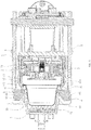
Fig. 2 is a sectional view of the mechanism according to the embodiment of the present invention (when the beverage brewing device is opened and the capsule is loaded); -
Fig.3 is a sectional view of the mechanism according to the embodiment of the present invention (when guiding surfaces of the guiding blocks come into contact with sidewalls of the first frame); -
Fig. 4 is a sectional view of the mechanism according to the embodiment of the present invention (when the guiding surfaces slide along the sidewalls of the first frame to impel the jaws to expand outward); -
Fig. 5 is a sectional view of the mechanism according to the embodiment of the present invention (when the two frames are closed for extraction); -
Fig. 6 is a sectional view of the mechanism according to the embodiment of the present invention (when the second frame is moved backward to come into contact with the stepped surface); -
Fig. 7 is a sectional view of the mechanism according to the embodiment of the present invention (when the second frame is moved backward to exert a thrust onto the rear end surfaces of the guiding blocks so as to impel the guiding blocks to turn outward, and the rear end surfaces of the clamp portions come into contact with the circular edge); -
Fig. 8 is a sectional view of the mechanism according to the embodiment of the present invention (when the second frame is moved backward to the rear end surfaces of the clamp portions to carry the capsule out, and the rear end surfaces of the guiding blocks come into contact with the clamp portions); -
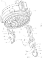
Fig. 9 is an assembly diagram of the guiding blocks, the jaws and the second frame according to the embodiment of the present invention; -
Fig. 10 is a perspective view of jaws according to the embodiment of the present invention; and -
Fig. 11 is a perspective view of guiding blocks according to the embodiment of the present invention. - To enable a further understanding of the present invention content of the invention herein, refer to the detailed description of the invention and the accompanying drawings below:
-
Fig. 1 - Fig. 11 show a preferred embodiment of a capsule delivery and rejection mechanism for a beverage brewing device. - The capsule delivery and rejection mechanism for a beverage brewing device comprises a
housing 1 having a front portion, a back portion, aloading port 11, and a dropping port 12;
afirst frame 2 positioned inside the front portion of thehousing 1, thefirst frame 2 having a left side, a right side, achamber 21 for holding acapsule 4 with acircular edge 41, thefirst frame 2 further having a liquid discharge passage, thefirst frame 2 being integrated with thehousing 1;
asecond frame 3 having a left side and a right side, disposed inside the back portion of thehousing 1 and being movable forward and backward relative to thefirst frame 2 under the driving of a driving structure, thesecond frame 3 having a liquid intake passage;
twojaws 5, eachjaw 5 having a front end and a rear end, the rear end of each jaw respectively rotatably connected to the left and right sides of thesecond frame 3;
two guidingblocks 6, sheet-shaped, each guidingblock 6 being rotatably arranged at front of eachjaw 5; and
a resetting mechanism for resetting the guiding blocks 6, the resetting mechanism being able to restore the guiding blocks 6 to the original positions after thesecond frame 2 is moved backward to carry thecapsule 4 out from thechamber 21. - Wherein, a
recess 31 for receiving eachjaw 5 is respectively provided on the left and right sidewalls of thesecond frame 3, and the rear end of eachjaw 5 is located inside therecess 31 and rotatably arranged at arotating shaft 52 inside therecess 31, and an elastic mechanism for allowing thejaws 52 to keep an inward clamping trend is provided on thesecond frame 3. The elastic mechanism in this embodiment is atorsion spring 7 provided on thespindles 52 at the rear end of thejaws 5; a first end of thetorsion spring 7 is hooked through asmall hole 53 formed on onejaw 5, while a second end of thetorsion spring 7 resists against the inner wall of therecess 31 of thejaw 5. - The front end of each
jaw 5 is aclamp portion 51 extending to the front of thesecond frame 3, theclamp portion 51 has a clamping opening capable of clamping thecircular edge 41 of thecapsule 4; anopening 512 which runs through in an axial direction and allows thecircular edge 41 of thecapsule 4 to insert therein is formed at an inner end of theclamp portion 51, and thebottom surface 513 of thisopening 512 is a cambered surface which is bent inward. - Each guiding
block 6 has arear end surface 62 and a guidingsurface 61 at the inner side of each guidingblock 6 which can be guided to open when the guidingsurface 61 touching thesidewalls 22 of thefirst frame 2; each guidingsurface 61 is a slope; the guiding blocks 6 can move forward with thejaws 5 from their original positions and touch thesidewalls 22 of thefirst frame 2, and then continue to move forward, at this time, eachsidewall 22 of thefirst frame 2 has an outward force onto each guidingsurface 61 so as to make thejaws 5 to be opened. -
Slots 54 are provided at the front ends of thejaws 5, the guiding blocks 6 are inserted into theslots 54 and rotatably connected into theslots 54; when in the original positions, the rear end faces of the guiding blocks 6 are in contact with the bottom surfaces of theslots 54. - A
shaft 63 is provided protruding on the upper and lower surfaces of each guidingblock 6, and eachjaw 5 has two throughholes 55 respectively locating at the upper and lower sides of eachslot 54 for two ends of eachshaft 63 to pass through; the upper and lower end surfaces 631 of theshafts 63 are slopes, and the upper and lowerinner walls 541 of eachslot 54 are also slopes. - An annual stepped
surface 23 is provided on the periphery of thefirst frame 2, when thesecond frame 3 is closed with thefirst frame 2 and then move backward, the steppedsurface 23 has a forward force onto therear end surface 62 of each guidingblock 6 to force each guidingblock 6 to rotate outward. - A stepped
surface 23 is provided on an outer side of thefirst frame 2. In a state where thesecond frame 2 is closed and then moved backward, the steppedsurface 23 exerts a forward thrust onto the rear end surfaces 62 of the guiding blocks 6 to force the guiding blocks 6 to rotate outward. - The
rear end surface 511 of eachclamp portion 51 can touch with thecircular edge 41 of thecapsule 4, when eachclamp portion 51 continues to move backward after touching with thecircular edge 41 of the capsule; therear end surface 511 of eachclamp portion 51 will pull thecircular edge 41 to carry thecapsule 4 out from thechamber 21. - In this embodiment, the resetting mechanism is a stopping
part 13 which is provided on ahousing 1 sidewall and in stopping fit to thesidewalls 64 of the guiding blocks 6; in the state where the guiding blocks 6 are turned over, thesidewall 64 of thesecond frame 3 moved backward to the guiding blocks 6 comes into contact with the stoppingpart 13 and continues to move backward, and the stoppingpart 13 exerts a forward thrust onto thesidewalls 64 of the guiding blocks 6 to impel the guiding blocks 6 to reset. - The operating process of the capsule delivery and rejection mechanism is as follows.
- Capsule loading: As shown in
Fig. 2 , the driving structure drives thesecond frame 3 to move backward to open, the twojaws 5 are closed and thus can hold thecapsule 4, and thecapsule 4 is loaded from theloading port 11 and placed between the two clamp portions, with thecircular edge 41 of thecapsule 4 being inserted from the slot 131 and supported on the bottom surface 132 of the slot 131. - Capsule delivery: As shown in
Fig. 3 - Fig. 5 , thesecond frame 3 is moved forward, and since thecapsule 4 is restrained between theclamp portions 51 at the front ends of the two jaws, the forward movement of thesecond frame 3 can drive the capsule and the jaws to move forward together; and in a state where thesecond frame 3 is moved forward so that thecapsule 4 is partially located inside thechamber 21, the guiding surfaces 61 of the guiding blocks 6 come into contact with thesidewalls 22 of thefirst frame 2 and then continue to move forward, eachsidewall 22 of thefirst frame 2 has an outward force onto each guidingsurface 61 so as to make thejaws 5 to be opened, in order to ensure that thecapsule 4 is further pushed into thechamber 21. Thesecond frame 3 is further moved forward, thefirst frame 2 and thesecond frame 3 are completely closed to form an extraction chamber, and thecircular edge 41 of thecapsule 4 is externally exposed from the periphery of the front end surface of thesecond frame 3 to complete the capsule loading. Meanwhile, the rear end surfaces 62 of the guiding blocks 6 are located at the rear portion of the steppedsurface 23 on thefirst frame 2 to complete the capsule loading. Then, extraction can be started. - Capsule rejection: As shown in
Fig. 6 - Fig. 8 , at the end of extraction, thesecond frame 3 is moved backward, the steppedsurface 23 exerts a forward thrust onto the rear end surfaces 62 of the guiding blocks 6 to impel the guiding blocks 6 to turn outward, and theclamp portions 51 slide along the outer wall of thefirst frame 2 until the rear end surfaces 511 of theclamp portions 51 come into contact with thecircular edge 41 of thecapsule 4. Thesecond frame 3 drives thejaws 5 to continue to move backward, and the rear end surfaces 511 of theclamp portions 51 push thecircular edge 41 and then carry thecapsule 4 out from thechamber 21. When thecapsule 4 is substantially removed from thechamber 21, thecapsule 4 drops from the dropping port 12 due to its gravity, and the guiding blocks 6 are restored to the original positions under the action of the resetting mechanism. In other words, in the backward movement process of thesecond frame 3, thejaws 5 and the guiding blocks 6, since the guiding blocks 6 are turned outward, and after the guiding blocks 6 are moved backward to thesidewalls 64 of the guiding blocks and the stoppingpart 13, the guiding blocks 6 are further moved backward. The stoppingpart 13 exerts a forward thrust onto thesidewalls 64 of the guiding blocks 6 to impel the guiding blocks 6 to restore to wait for the next capsule delivery.
Claims (9)
- A capsule delivery and rejection mechanism in a beverage brewing device, comprising:a housing (1) having a front portion, a back portion, a loading port (11), and a dropping port (12);a first frame (2) positioned inside the front portion of the housing (1), the first frame (2) having a left side, a right side, a chamber (21) for holding a capsule (4) with a circular edge (41);a second frame (3) having a left side and a right side, disposed inside the back portion of the housing (1) and being movable forward and backward relative to the first frame (2);characterized in that, the capsule delivery and rejection mechanism further comprises:two jaws (5), each jaw (5) having a front end and a rear end, the rear end of each jaw respectively rotatably connected to the left and right sides of the second frame (3), the front end of each jaw (5) being a clamp portion (51) extending to the front of the second frame (3), the clamp portion (51) having a clamping opening capable of clamping the circular edge (41) of the capsule (4);two guiding blocks (6), each guiding block (6) being rotatably arranged at front of each jaw (5), each guiding block (6) having a rear end surface (62) and a guiding surface (61) at the inner side of each guiding block (6) which can be guided to open when the guiding surface (61) touching the sidewalls (22) of the first frame (2), the guiding blocks (6) can move forward with the jaws (5) from their original positions and touch the sidewalls (22) of the first frame (2), and then continue to move forward, at this time, each sidewall (22) of the first frame (2) has an outward force onto each guiding surface (61) so as to make the jaws (5) to be opened;a resetting mechanism for resetting the guiding blocks (6), the resetting mechanism being able to restore the guiding blocks (6) to the original positions after the second frame (2) is moved backward to carry the capsule (4) out from the chamber (21);therein, an annual stepped surface (23) is provided on the periphery of the first frame (2), when the second frame (3) is closed with the first frame (2) and then move backward, the stepped surface (23) has a forward force onto the rear end surface (62) of each guiding block (6) to force each guiding block (6) to rotate outward; andthe rear end surface (511) of each clamp portion (51) can touch with the circular edge (41) of the capsule (4), when each clamp portion (51) continues to move backward after touching with the circular edge (41) of the capsule; the rear end surface (511) of each clamp portion (51) will pull the circular edge (41) to carry the capsule (4) out from the chamber (21).
- The capsule delivery and rejection mechanism according to claim 1, characterized in that, an elastic mechanism for enabling the jaws (5) to keep an inward clamping trend is provided on the second frame (3).
- The capsule delivery and rejection mechanism according to claim 2, characterized in that, the elastic mechanism is a torsion spring (7) provided on a spindle (52) at the rear end of the jaws (5).
- The capsule delivery and rejection mechanism according to claim 3, characterized in that, a recess (31) for receiving each jaw (5) is respectively provided on the left and right sidewalls of the second frame (3), and the rear end of each jaw (5) is located inside the recess (31); a first end of the torsion spring (7) is hooked through a small hole (53) formed on one jaw (5), while a second end of the torsion spring (7) resists against the inner wall of the recess (31) of the jaw (5).
- The capsule delivery and rejection mechanism according to claim 1, characterized in that, slots (54) are provided at the front ends of the jaws (5); the guiding blocks (6) are inserted into the slots (54) and rotatably connected into the slots (54); when in the original positions, the rear end faces of the guiding blocks (6) are in contact with the bottom surfaces of the slots (54).
- The capsule delivery and rejection mechanism according to claim 5, characterized in that, a shaft (63) is provided protruding on the upper and lower surfaces of each guiding block (6), and each jaw (5) has two through holes (55) respectively locating at the upper and lower sides of each slot (54) for two ends of each shaft (63) to pass through; the upper and lower end surfaces (631) of the shafts (63) are slopes, and the upper and lower inner walls (541) of each slot (54) are also slopes.
- The capsule delivery and rejection mechanism according to claim 1, characterized in that, the resetting mechanism is a stopping part (13) which is provided on a housing (1) sidewall and in stopping fit to the sidewalls 64 of the guiding blocks (6); in the state where the guiding blocks (6) are turned over, the sidewall (64) of the second frame (3) moved backward to the guiding blocks (6) comes into contact with the stopping part (13) and continues to move backward, and the stopping part (13) exerts a forward thrust onto the sidewalls (64) of the guiding blocks (6) to impel the guiding blocks (6) to reset.
- The capsule delivery and rejection mechanism according to claim 1, characterized in that, each guiding surface (61) is a slope.
- The capsule delivery and rejection mechanism according to claim 1, characterized in that, an opening (512) which runs through in an axial direction and allows the circular edge (41) of the capsule (4) to insert therein is formed at an inner end of the clamp portion (51), and the bottom surface (513) of this opening (512) is a cambered surface which is bent inward.
Applications Claiming Priority (2)
| Application Number | Priority Date | Filing Date | Title |
|---|---|---|---|
| CN201410195743.9A CN103989407B (en) | 2014-05-09 | 2014-05-09 | The package delivering and releasing mechanism of beverage brewing device |
| PCT/CN2014/000828 WO2015168824A1 (en) | 2014-05-09 | 2014-09-04 | Pack feeding/detaching mechanism for beverage brewing device |
Publications (3)
| Publication Number | Publication Date |
|---|---|
| EP3141165A1 true EP3141165A1 (en) | 2017-03-15 |
| EP3141165A4 EP3141165A4 (en) | 2017-07-19 |
| EP3141165B1 EP3141165B1 (en) | 2018-10-31 |
Family
ID=51303939
Family Applications (1)
| Application Number | Title | Priority Date | Filing Date |
|---|---|---|---|
| EP14891489.8A Active EP3141165B1 (en) | 2014-05-09 | 2014-09-04 | Pack feeding/detaching mechanism for beverage brewing device |
Country Status (3)
| Country | Link |
|---|---|
| EP (1) | EP3141165B1 (en) |
| CN (1) | CN103989407B (en) |
| WO (1) | WO2015168824A1 (en) |
Families Citing this family (10)
| Publication number | Priority date | Publication date | Assignee | Title |
|---|---|---|---|---|
| CN103989407B (en) * | 2014-05-09 | 2016-05-11 | 宁波全景电器技术有限公司 | The package delivering and releasing mechanism of beverage brewing device |
| EP2989943B1 (en) * | 2014-09-01 | 2020-07-08 | Eugster/Frismag AG | Brewing device for extracting a portion capsule |
| EP3143911A1 (en) * | 2015-09-17 | 2017-03-22 | Mocoffee AG | Apparatus for producing a beverage from a capsule |
| PT3143910T (en) * | 2015-09-17 | 2018-11-05 | Mocoffee Europe Unipessoal Lda | Apparatus for producing a beverage from a capsule |
| CN106136915B (en) * | 2016-08-19 | 2018-11-13 | 宁波全景电器技术有限公司 | The improved beverage extraction plant of structure is with sending de- turn-up mechanism |
| CN106264156B (en) * | 2016-09-13 | 2018-09-25 | 宁波全景电器技术有限公司 | Beverage extraction plant is with sending de- turn-up mechanism |
| CN106618217B (en) * | 2016-11-23 | 2022-11-25 | 宁波亚特电器有限公司 | Package conveying and removing mechanism in brewing set |
| KR101798840B1 (en) | 2017-05-17 | 2017-11-17 | 주식회사 레고켐 바이오사이언스 | Novel Compounds as Autotaxin Inhibitors and Pharmaceutical Compositions Comprising the Same |
| CN108078390B (en) * | 2018-01-19 | 2023-07-21 | 宁波锦宇电器有限公司 | Capsule coffee machine |
| WO2020132864A1 (en) * | 2018-12-25 | 2020-07-02 | 深圳市西啡科技有限公司 | Beverage preparation device and beverage preparation apparatus |
Family Cites Families (13)
| Publication number | Priority date | Publication date | Assignee | Title |
|---|---|---|---|---|
| ITMI20050854A1 (en) * | 2005-05-12 | 2006-11-13 | Perfect Steam Appliances Ltd | INFUSION GROUP FOR DRINK PREPARATION MACHINES |
| ITFI20060194A1 (en) * | 2006-08-04 | 2008-02-05 | Saeco Ipr Ltd | INFUSION DEVICE FOR THE PREPARATION OF DRINKS FROM SINGLE-DOSE CAPSULES |
| ITFI20070028A1 (en) * | 2007-02-07 | 2008-08-08 | Saeco Ipr Ltd | INFUSION DEVICE FOR THE PREPARATION OF DRINKS FROM SINGLE-DOSE CAPSULES WITH A CAPSULES CENTERING DEVICE. |
| ITFI20070120A1 (en) * | 2007-05-23 | 2008-11-24 | Mac Design S A S Di R Maccioni | POSITIONING AND EXTRACTION GROUP OF DISPOSABLE PODS FOR COFFEE MACHINES |
| CN101791196B (en) * | 2010-02-09 | 2011-07-27 | 宁波三A集团电器有限公司 | Packet sending and falling structure of beverage brewing device |
| CN201822642U (en) * | 2010-09-20 | 2011-05-11 | 宁波贝仕迪电器有限公司 | Rubber bag type coffee machine |
| CN201987327U (en) * | 2010-12-27 | 2011-09-28 | 苏州工业园区咖乐美电器有限公司 | Manual capsule coffee machine |
| CN102429584B (en) * | 2011-12-13 | 2013-09-25 | 宁波三A集团电器有限公司 | Bag feeding and discharging structure for beverage brewing device |
| CN202426301U (en) * | 2011-12-13 | 2012-09-12 | 宁波三A集团电器有限公司 | Package conveying and removing structure of beverage brewing device |
| AU2012371223A1 (en) * | 2012-02-28 | 2014-09-18 | Nestec S.A. | Capsule-controlled motorized brewing unit |
| CN103519693A (en) * | 2013-08-01 | 2014-01-22 | 广东顺德高达科菲电器制造有限公司 | Beverage package automatic falling-off mechanism of beverage brewing machine |
| CN203861028U (en) * | 2014-05-09 | 2014-10-08 | 宁波全景电器技术有限公司 | Bag conveying and bag unpacking mechanism for beverage brewing device |
| CN103989407B (en) * | 2014-05-09 | 2016-05-11 | 宁波全景电器技术有限公司 | The package delivering and releasing mechanism of beverage brewing device |
-
2014
- 2014-05-09 CN CN201410195743.9A patent/CN103989407B/en active Active
- 2014-09-04 EP EP14891489.8A patent/EP3141165B1/en active Active
- 2014-09-04 WO PCT/CN2014/000828 patent/WO2015168824A1/en active Application Filing
Also Published As
| Publication number | Publication date |
|---|---|
| EP3141165B1 (en) | 2018-10-31 |
| CN103989407A (en) | 2014-08-20 |
| WO2015168824A1 (en) | 2015-11-12 |
| EP3141165A4 (en) | 2017-07-19 |
| CN103989407B (en) | 2016-05-11 |
Similar Documents
| Publication | Publication Date | Title |
|---|---|---|
| EP3141165B1 (en) | Pack feeding/detaching mechanism for beverage brewing device | |
| US9259118B2 (en) | Beverage extraction device convenient for package removal | |
| JP5087734B2 (en) | Automatic drop-off mechanism of coffee drip bag in coffee maker | |
| EP3111811A1 (en) | Bag feeding and releasing mechanism of beverage extracting device | |
| JP6671295B2 (en) | Beverage brewing unit, especially for machines for preparing beverages from capsules | |
| JP5492093B2 (en) | Extraction unit for preparing a beverage from a single use package and apparatus comprising the unit | |
| EP2803301B1 (en) | Beverage package dropping structure in beverage extraction apparatus | |
| US8667889B2 (en) | Machine for the preparation of beverages by infusion using cartridges | |
| US8176840B2 (en) | Brewing device and brewing capsule system with a capsule holder for facilitating insertion and removal of capsules | |
| EP3501348B1 (en) | Structure-improved package feeding and removing mechanism for beverage extraction device | |
| EP3141166B1 (en) | Beverage brewing device allowing beverage capsule to be removed easily | |
| EP2520203A1 (en) | Apparatus for preparing a beverage starting from a powder material contained in a sealed cartridge | |
| WO2013166853A1 (en) | Automatic packet release mechanism of beverage preparation apparatus | |
| EP2915465A1 (en) | Beverage production device for receiving a capsule for the preparation of a beverage | |
| US20220071434A1 (en) | Capsule coffee machine | |
| CN203861028U (en) | Bag conveying and bag unpacking mechanism for beverage brewing device | |
| EP2606779A1 (en) | Infusion unit | |
| US10524607B2 (en) | Coffee brewer | |
| US10368684B2 (en) | Machine for the preparation of liquid products using capsules | |
| KR102142405B1 (en) | Apparatus for pivoting capsule receptacle of capsule coffee machine | |
| CN113100635A (en) | Capsule-based beverage extraction device | |
| ITBS20100198A1 (en) | INFUSION GROUP WITH PALLET EXTRACTION PALLET |
Legal Events
| Date | Code | Title | Description |
|---|---|---|---|
| STAA | Information on the status of an ep patent application or granted ep patent |
Free format text: STATUS: THE INTERNATIONAL PUBLICATION HAS BEEN MADE |
|
| PUAI | Public reference made under article 153(3) epc to a published international application that has entered the european phase |
Free format text: ORIGINAL CODE: 0009012 |
|
| STAA | Information on the status of an ep patent application or granted ep patent |
Free format text: STATUS: REQUEST FOR EXAMINATION WAS MADE |
|
| 17P | Request for examination filed |
Effective date: 20161122 |
|
| AK | Designated contracting states |
Kind code of ref document: A1 Designated state(s): AL AT BE BG CH CY CZ DE DK EE ES FI FR GB GR HR HU IE IS IT LI LT LU LV MC MK MT NL NO PL PT RO RS SE SI SK SM TR |
|
| AX | Request for extension of the european patent |
Extension state: BA ME |
|
| A4 | Supplementary search report drawn up and despatched |
Effective date: 20170620 |
|
| RIC1 | Information provided on ipc code assigned before grant |
Ipc: A47J 31/36 20060101ALI20170613BHEP Ipc: A47J 31/44 20060101AFI20170613BHEP Ipc: A47J 31/40 20060101ALI20170613BHEP |
|
| DAX | Request for extension of the european patent (deleted) | ||
| GRAP | Despatch of communication of intention to grant a patent |
Free format text: ORIGINAL CODE: EPIDOSNIGR1 |
|
| STAA | Information on the status of an ep patent application or granted ep patent |
Free format text: STATUS: GRANT OF PATENT IS INTENDED |
|
| INTG | Intention to grant announced |
Effective date: 20180716 |
|
| GRAS | Grant fee paid |
Free format text: ORIGINAL CODE: EPIDOSNIGR3 |
|
| GRAA | (expected) grant |
Free format text: ORIGINAL CODE: 0009210 |
|
| STAA | Information on the status of an ep patent application or granted ep patent |
Free format text: STATUS: THE PATENT HAS BEEN GRANTED |
|
| AK | Designated contracting states |
Kind code of ref document: B1 Designated state(s): AL AT BE BG CH CY CZ DE DK EE ES FI FR GB GR HR HU IE IS IT LI LT LU LV MC MK MT NL NO PL PT RO RS SE SI SK SM TR |
|
| REG | Reference to a national code |
Ref country code: CH Ref legal event code: EP Ref country code: GB Ref legal event code: FG4D |
|
| REG | Reference to a national code |
Ref country code: AT Ref legal event code: REF Ref document number: 1058363 Country of ref document: AT Kind code of ref document: T Effective date: 20181115 |
|
| REG | Reference to a national code |
Ref country code: IE Ref legal event code: FG4D |
|
| REG | Reference to a national code |
Ref country code: DE Ref legal event code: R096 Ref document number: 602014035393 Country of ref document: DE |
|
| REG | Reference to a national code |
Ref country code: NL Ref legal event code: MP Effective date: 20181031 |
|
| REG | Reference to a national code |
Ref country code: LT Ref legal event code: MG4D |
|
| REG | Reference to a national code |
Ref country code: AT Ref legal event code: MK05 Ref document number: 1058363 Country of ref document: AT Kind code of ref document: T Effective date: 20181031 |
|
| PG25 | Lapsed in a contracting state [announced via postgrant information from national office to epo] |
Ref country code: LV Free format text: LAPSE BECAUSE OF FAILURE TO SUBMIT A TRANSLATION OF THE DESCRIPTION OR TO PAY THE FEE WITHIN THE PRESCRIBED TIME-LIMIT Effective date: 20181031 Ref country code: AT Free format text: LAPSE BECAUSE OF FAILURE TO SUBMIT A TRANSLATION OF THE DESCRIPTION OR TO PAY THE FEE WITHIN THE PRESCRIBED TIME-LIMIT Effective date: 20181031 Ref country code: IS Free format text: LAPSE BECAUSE OF FAILURE TO SUBMIT A TRANSLATION OF THE DESCRIPTION OR TO PAY THE FEE WITHIN THE PRESCRIBED TIME-LIMIT Effective date: 20190228 Ref country code: FI Free format text: LAPSE BECAUSE OF FAILURE TO SUBMIT A TRANSLATION OF THE DESCRIPTION OR TO PAY THE FEE WITHIN THE PRESCRIBED TIME-LIMIT Effective date: 20181031 Ref country code: BG Free format text: LAPSE BECAUSE OF FAILURE TO SUBMIT A TRANSLATION OF THE DESCRIPTION OR TO PAY THE FEE WITHIN THE PRESCRIBED TIME-LIMIT Effective date: 20190131 Ref country code: NO Free format text: LAPSE BECAUSE OF FAILURE TO SUBMIT A TRANSLATION OF THE DESCRIPTION OR TO PAY THE FEE WITHIN THE PRESCRIBED TIME-LIMIT Effective date: 20190131 Ref country code: HR Free format text: LAPSE BECAUSE OF FAILURE TO SUBMIT A TRANSLATION OF THE DESCRIPTION OR TO PAY THE FEE WITHIN THE PRESCRIBED TIME-LIMIT Effective date: 20181031 Ref country code: PL Free format text: LAPSE BECAUSE OF FAILURE TO SUBMIT A TRANSLATION OF THE DESCRIPTION OR TO PAY THE FEE WITHIN THE PRESCRIBED TIME-LIMIT Effective date: 20181031 Ref country code: ES Free format text: LAPSE BECAUSE OF FAILURE TO SUBMIT A TRANSLATION OF THE DESCRIPTION OR TO PAY THE FEE WITHIN THE PRESCRIBED TIME-LIMIT Effective date: 20181031 Ref country code: LT Free format text: LAPSE BECAUSE OF FAILURE TO SUBMIT A TRANSLATION OF THE DESCRIPTION OR TO PAY THE FEE WITHIN THE PRESCRIBED TIME-LIMIT Effective date: 20181031 |
|
| PG25 | Lapsed in a contracting state [announced via postgrant information from national office to epo] |
Ref country code: SE Free format text: LAPSE BECAUSE OF FAILURE TO SUBMIT A TRANSLATION OF THE DESCRIPTION OR TO PAY THE FEE WITHIN THE PRESCRIBED TIME-LIMIT Effective date: 20181031 Ref country code: GR Free format text: LAPSE BECAUSE OF FAILURE TO SUBMIT A TRANSLATION OF THE DESCRIPTION OR TO PAY THE FEE WITHIN THE PRESCRIBED TIME-LIMIT Effective date: 20190201 Ref country code: NL Free format text: LAPSE BECAUSE OF FAILURE TO SUBMIT A TRANSLATION OF THE DESCRIPTION OR TO PAY THE FEE WITHIN THE PRESCRIBED TIME-LIMIT Effective date: 20181031 Ref country code: PT Free format text: LAPSE BECAUSE OF FAILURE TO SUBMIT A TRANSLATION OF THE DESCRIPTION OR TO PAY THE FEE WITHIN THE PRESCRIBED TIME-LIMIT Effective date: 20190301 Ref country code: AL Free format text: LAPSE BECAUSE OF FAILURE TO SUBMIT A TRANSLATION OF THE DESCRIPTION OR TO PAY THE FEE WITHIN THE PRESCRIBED TIME-LIMIT Effective date: 20181031 Ref country code: RS Free format text: LAPSE BECAUSE OF FAILURE TO SUBMIT A TRANSLATION OF THE DESCRIPTION OR TO PAY THE FEE WITHIN THE PRESCRIBED TIME-LIMIT Effective date: 20181031 |
|
| PG25 | Lapsed in a contracting state [announced via postgrant information from national office to epo] |
Ref country code: CZ Free format text: LAPSE BECAUSE OF FAILURE TO SUBMIT A TRANSLATION OF THE DESCRIPTION OR TO PAY THE FEE WITHIN THE PRESCRIBED TIME-LIMIT Effective date: 20181031 Ref country code: DK Free format text: LAPSE BECAUSE OF FAILURE TO SUBMIT A TRANSLATION OF THE DESCRIPTION OR TO PAY THE FEE WITHIN THE PRESCRIBED TIME-LIMIT Effective date: 20181031 Ref country code: IT Free format text: LAPSE BECAUSE OF FAILURE TO SUBMIT A TRANSLATION OF THE DESCRIPTION OR TO PAY THE FEE WITHIN THE PRESCRIBED TIME-LIMIT Effective date: 20181031 |
|
| REG | Reference to a national code |
Ref country code: DE Ref legal event code: R097 Ref document number: 602014035393 Country of ref document: DE |
|
| PG25 | Lapsed in a contracting state [announced via postgrant information from national office to epo] |
Ref country code: RO Free format text: LAPSE BECAUSE OF FAILURE TO SUBMIT A TRANSLATION OF THE DESCRIPTION OR TO PAY THE FEE WITHIN THE PRESCRIBED TIME-LIMIT Effective date: 20181031 Ref country code: SK Free format text: LAPSE BECAUSE OF FAILURE TO SUBMIT A TRANSLATION OF THE DESCRIPTION OR TO PAY THE FEE WITHIN THE PRESCRIBED TIME-LIMIT Effective date: 20181031 Ref country code: EE Free format text: LAPSE BECAUSE OF FAILURE TO SUBMIT A TRANSLATION OF THE DESCRIPTION OR TO PAY THE FEE WITHIN THE PRESCRIBED TIME-LIMIT Effective date: 20181031 Ref country code: SM Free format text: LAPSE BECAUSE OF FAILURE TO SUBMIT A TRANSLATION OF THE DESCRIPTION OR TO PAY THE FEE WITHIN THE PRESCRIBED TIME-LIMIT Effective date: 20181031 |
|
| PLBE | No opposition filed within time limit |
Free format text: ORIGINAL CODE: 0009261 |
|
| STAA | Information on the status of an ep patent application or granted ep patent |
Free format text: STATUS: NO OPPOSITION FILED WITHIN TIME LIMIT |
|
| 26N | No opposition filed |
Effective date: 20190801 |
|
| PG25 | Lapsed in a contracting state [announced via postgrant information from national office to epo] |
Ref country code: SI Free format text: LAPSE BECAUSE OF FAILURE TO SUBMIT A TRANSLATION OF THE DESCRIPTION OR TO PAY THE FEE WITHIN THE PRESCRIBED TIME-LIMIT Effective date: 20181031 |
|
| PG25 | Lapsed in a contracting state [announced via postgrant information from national office to epo] |
Ref country code: TR Free format text: LAPSE BECAUSE OF FAILURE TO SUBMIT A TRANSLATION OF THE DESCRIPTION OR TO PAY THE FEE WITHIN THE PRESCRIBED TIME-LIMIT Effective date: 20181031 |
|
| PG25 | Lapsed in a contracting state [announced via postgrant information from national office to epo] |
Ref country code: MC Free format text: LAPSE BECAUSE OF FAILURE TO SUBMIT A TRANSLATION OF THE DESCRIPTION OR TO PAY THE FEE WITHIN THE PRESCRIBED TIME-LIMIT Effective date: 20181031 |
|
| REG | Reference to a national code |
Ref country code: CH Ref legal event code: PL |
|
| PG25 | Lapsed in a contracting state [announced via postgrant information from national office to epo] |
Ref country code: LI Free format text: LAPSE BECAUSE OF NON-PAYMENT OF DUE FEES Effective date: 20190930 Ref country code: CH Free format text: LAPSE BECAUSE OF NON-PAYMENT OF DUE FEES Effective date: 20190930 Ref country code: LU Free format text: LAPSE BECAUSE OF NON-PAYMENT OF DUE FEES Effective date: 20190904 Ref country code: IE Free format text: LAPSE BECAUSE OF NON-PAYMENT OF DUE FEES Effective date: 20190904 |
|
| REG | Reference to a national code |
Ref country code: BE Ref legal event code: MM Effective date: 20190930 |
|
| PG25 | Lapsed in a contracting state [announced via postgrant information from national office to epo] |
Ref country code: BE Free format text: LAPSE BECAUSE OF NON-PAYMENT OF DUE FEES Effective date: 20190930 |
|
| GBPC | Gb: european patent ceased through non-payment of renewal fee |
Effective date: 20190904 |
|
| PG25 | Lapsed in a contracting state [announced via postgrant information from national office to epo] |
Ref country code: FR Free format text: LAPSE BECAUSE OF NON-PAYMENT OF DUE FEES Effective date: 20190930 Ref country code: GB Free format text: LAPSE BECAUSE OF NON-PAYMENT OF DUE FEES Effective date: 20190904 |
|
| PG25 | Lapsed in a contracting state [announced via postgrant information from national office to epo] |
Ref country code: CY Free format text: LAPSE BECAUSE OF FAILURE TO SUBMIT A TRANSLATION OF THE DESCRIPTION OR TO PAY THE FEE WITHIN THE PRESCRIBED TIME-LIMIT Effective date: 20181031 |
|
| PG25 | Lapsed in a contracting state [announced via postgrant information from national office to epo] |
Ref country code: MT Free format text: LAPSE BECAUSE OF FAILURE TO SUBMIT A TRANSLATION OF THE DESCRIPTION OR TO PAY THE FEE WITHIN THE PRESCRIBED TIME-LIMIT Effective date: 20181031 Ref country code: HU Free format text: LAPSE BECAUSE OF FAILURE TO SUBMIT A TRANSLATION OF THE DESCRIPTION OR TO PAY THE FEE WITHIN THE PRESCRIBED TIME-LIMIT; INVALID AB INITIO Effective date: 20140904 |
|
| PG25 | Lapsed in a contracting state [announced via postgrant information from national office to epo] |
Ref country code: MK Free format text: LAPSE BECAUSE OF FAILURE TO SUBMIT A TRANSLATION OF THE DESCRIPTION OR TO PAY THE FEE WITHIN THE PRESCRIBED TIME-LIMIT Effective date: 20181031 |
|
| PGFP | Annual fee paid to national office [announced via postgrant information from national office to epo] |
Ref country code: DE Payment date: 20230928 Year of fee payment: 10 |