JP6671295B2 - Beverage brewing unit, especially for machines for preparing beverages from capsules - Google Patents
Beverage brewing unit, especially for machines for preparing beverages from capsules Download PDFInfo
- Publication number
- JP6671295B2 JP6671295B2 JP2016560511A JP2016560511A JP6671295B2 JP 6671295 B2 JP6671295 B2 JP 6671295B2 JP 2016560511 A JP2016560511 A JP 2016560511A JP 2016560511 A JP2016560511 A JP 2016560511A JP 6671295 B2 JP6671295 B2 JP 6671295B2
- Authority
- JP
- Japan
- Prior art keywords
- capsule
- brewing unit
- pair
- jaws
- beverage
- Prior art date
- Legal status (The legal status is an assumption and is not a legal conclusion. Google has not performed a legal analysis and makes no representation as to the accuracy of the status listed.)
- Active
Links
- 239000002775 capsule Substances 0.000 title claims description 249
- 235000013361 beverage Nutrition 0.000 title claims description 90
- 238000003780 insertion Methods 0.000 claims description 46
- 230000037431 insertion Effects 0.000 claims description 46
- 238000003825 pressing Methods 0.000 claims description 20
- 238000003860 storage Methods 0.000 claims description 19
- 230000005291 magnetic effect Effects 0.000 claims description 13
- 230000005484 gravity Effects 0.000 claims description 9
- 238000002360 preparation method Methods 0.000 claims description 8
- 238000007599 discharging Methods 0.000 claims description 3
- 241000255925 Diptera Species 0.000 claims 1
- 239000007788 liquid Substances 0.000 description 15
- XLYOFNOQVPJJNP-UHFFFAOYSA-N water Substances O XLYOFNOQVPJJNP-UHFFFAOYSA-N 0.000 description 14
- 230000000295 complement effect Effects 0.000 description 10
- 239000004615 ingredient Substances 0.000 description 6
- 235000016213 coffee Nutrition 0.000 description 5
- 235000013353 coffee beverage Nutrition 0.000 description 5
- 239000000284 extract Substances 0.000 description 5
- 238000000605 extraction Methods 0.000 description 5
- 230000005294 ferromagnetic effect Effects 0.000 description 5
- 238000002347 injection Methods 0.000 description 5
- 239000007924 injection Substances 0.000 description 5
- 238000012545 processing Methods 0.000 description 5
- 238000005520 cutting process Methods 0.000 description 4
- 238000010438 heat treatment Methods 0.000 description 4
- 238000004519 manufacturing process Methods 0.000 description 4
- 238000005119 centrifugation Methods 0.000 description 3
- 238000010586 diagram Methods 0.000 description 3
- 238000011068 loading method Methods 0.000 description 3
- 230000007246 mechanism Effects 0.000 description 3
- 241001122767 Theaceae Species 0.000 description 2
- 238000001914 filtration Methods 0.000 description 2
- 230000004308 accommodation Effects 0.000 description 1
- 238000013459 approach Methods 0.000 description 1
- 230000000712 assembly Effects 0.000 description 1
- 238000000429 assembly Methods 0.000 description 1
- 230000001419 dependent effect Effects 0.000 description 1
- 238000013461 design Methods 0.000 description 1
- 230000000694 effects Effects 0.000 description 1
- 238000011049 filling Methods 0.000 description 1
- 239000011521 glass Substances 0.000 description 1
- 238000007373 indentation Methods 0.000 description 1
- 235000021539 instant coffee Nutrition 0.000 description 1
- 238000002386 leaching Methods 0.000 description 1
- 239000012528 membrane Substances 0.000 description 1
- 239000012254 powdered material Substances 0.000 description 1
- 230000000452 restraining effect Effects 0.000 description 1
- 230000000717 retained effect Effects 0.000 description 1
- 238000007789 sealing Methods 0.000 description 1
- 235000013616 tea Nutrition 0.000 description 1
- 238000013519 translation Methods 0.000 description 1
Images


Classifications
-
- A—HUMAN NECESSITIES
- A47—FURNITURE; DOMESTIC ARTICLES OR APPLIANCES; COFFEE MILLS; SPICE MILLS; SUCTION CLEANERS IN GENERAL
- A47J—KITCHEN EQUIPMENT; COFFEE MILLS; SPICE MILLS; APPARATUS FOR MAKING BEVERAGES
- A47J31/00—Apparatus for making beverages
- A47J31/24—Coffee-making apparatus in which hot water is passed through the filter under pressure, i.e. in which the coffee grounds are extracted under pressure
- A47J31/34—Coffee-making apparatus in which hot water is passed through the filter under pressure, i.e. in which the coffee grounds are extracted under pressure with hot water under liquid pressure
- A47J31/36—Coffee-making apparatus in which hot water is passed through the filter under pressure, i.e. in which the coffee grounds are extracted under pressure with hot water under liquid pressure with mechanical pressure-producing means
- A47J31/3604—Coffee-making apparatus in which hot water is passed through the filter under pressure, i.e. in which the coffee grounds are extracted under pressure with hot water under liquid pressure with mechanical pressure-producing means with a mechanism arranged to move the brewing chamber between loading, infusing and ejecting stations
- A47J31/3623—Cartridges being employed
- A47J31/3633—Means to perform transfer from a loading position to an infusing position
-
- A—HUMAN NECESSITIES
- A47—FURNITURE; DOMESTIC ARTICLES OR APPLIANCES; COFFEE MILLS; SPICE MILLS; SUCTION CLEANERS IN GENERAL
- A47J—KITCHEN EQUIPMENT; COFFEE MILLS; SPICE MILLS; APPARATUS FOR MAKING BEVERAGES
- A47J31/00—Apparatus for making beverages
- A47J31/22—Centrifuges for producing filtered coffee
-
- A—HUMAN NECESSITIES
- A47—FURNITURE; DOMESTIC ARTICLES OR APPLIANCES; COFFEE MILLS; SPICE MILLS; SUCTION CLEANERS IN GENERAL
- A47J—KITCHEN EQUIPMENT; COFFEE MILLS; SPICE MILLS; APPARATUS FOR MAKING BEVERAGES
- A47J31/00—Apparatus for making beverages
- A47J31/24—Coffee-making apparatus in which hot water is passed through the filter under pressure, i.e. in which the coffee grounds are extracted under pressure
- A47J31/34—Coffee-making apparatus in which hot water is passed through the filter under pressure, i.e. in which the coffee grounds are extracted under pressure with hot water under liquid pressure
- A47J31/36—Coffee-making apparatus in which hot water is passed through the filter under pressure, i.e. in which the coffee grounds are extracted under pressure with hot water under liquid pressure with mechanical pressure-producing means
- A47J31/3604—Coffee-making apparatus in which hot water is passed through the filter under pressure, i.e. in which the coffee grounds are extracted under pressure with hot water under liquid pressure with mechanical pressure-producing means with a mechanism arranged to move the brewing chamber between loading, infusing and ejecting stations
- A47J31/3623—Cartridges being employed
- A47J31/3638—Means to eject the cartridge after brewing
-
- A—HUMAN NECESSITIES
- A47—FURNITURE; DOMESTIC ARTICLES OR APPLIANCES; COFFEE MILLS; SPICE MILLS; SUCTION CLEANERS IN GENERAL
- A47J—KITCHEN EQUIPMENT; COFFEE MILLS; SPICE MILLS; APPARATUS FOR MAKING BEVERAGES
- A47J31/00—Apparatus for making beverages
- A47J31/40—Beverage-making apparatus with dispensing means for adding a measured quantity of ingredients, e.g. coffee, water, sugar, cocoa, milk, tea
- A47J31/407—Beverage-making apparatus with dispensing means for adding a measured quantity of ingredients, e.g. coffee, water, sugar, cocoa, milk, tea with ingredient-containing cartridges; Cartridge-perforating means
Description
本発明は、飲料原材料を収容する、特に、カプセルから飲料を調製するためのマシン用の飲料淹出ユニットに関する。本発明は、更に、こうした淹出ユニットを備える飲料調製マシンに関する。 The present invention relates to a beverage brewing unit for a machine for storing beverage ingredients, in particular for preparing a beverage from capsules. The invention further relates to a beverage preparation machine comprising such a brewing unit.
ある種の飲料調製マシンでは、抽出若しくは溶解されるべき原材料及び/又はマシン内にて保管され、自動的に供与されるか、そうでなければ、飲料調製時に添加される原材料を収容するカプセルを使用する。いくつかの飲料マシンは、液体(通常は水である)用のポンプを含む充填手段を有する。このポンプは、低温であるか又は加熱手段によりよく加熱された、水供給源からの液体を圧送する。 In some beverage preparation machines, a capsule containing the ingredients to be extracted or dissolved and / or the ingredients stored in the machine and automatically supplied or otherwise added during beverage preparation is provided. use. Some beverage machines have filling means that include a pump for liquids (usually water). The pump pumps liquid from a water supply, which is cold or well heated by a heating means.
特に、コーヒー調製の分野においては、飲料原材料を収容するカプセルを淹出ユニット内に挿入するマシンが広く開発されてきた。淹出ユニットはカプセルの周囲で密封され、カプセルの第1の面にて水が注入され、カプセルの密閉容積部内で飲料が生成され、淹出された飲料がカプセルの第2の面から排出され、カップ又はグラスなどの受器へと回収され得る。 In particular, in the field of coffee preparation, machines for inserting capsules containing beverage ingredients into a brewing unit have been widely developed. The brewing unit is sealed around the capsule, water is injected at a first side of the capsule, a beverage is produced in a closed volume of the capsule, and the brewed beverage is discharged from a second side of the capsule. , Cups or glasses.
使用時、カプセルの挿入及びカプセルの取り出しを容易にするための淹出ユニットが開発されてきた。 In use, brewing units have been developed to facilitate capsule insertion and capsule removal.
欧州特許第1757212(B1)号は、これら淹出ユニットの一例に関する。このデバイスは、フレームと、カプセルのための固定収容部と、フレームに対し摺動関係にて取り付けられた可動収容部と、収容部をカプセルの周りで定常かつ流体密状態にて閉じることを可能にする一方で、また、再度開く際に作用しかつ内部淹出圧力により発生する反力に抗する機械系を設ける1つ又は2つのナックルジョイント機構と、ナックルジョイント機構を直接てこにより動かすためのハンドルとを備える。こうしたデバイスは、フレーム内の通路を通じた垂直(重力)落下によるカプセルの挿入と、挿入方向と同じ方向における使用済みカプセルの取り出しとを可能にする単純なアセンブリを形成する。淹出ユニットの可動収容部はハンドルにより手動で作動される。 EP 1757212 (B1) relates to an example of these brewing units. The device allows the frame, a fixed housing for the capsule, a movable housing mounted in sliding relation to the frame, and a steady and fluid-tight closure of the housing around the capsule And one or two knuckle joint mechanisms providing a mechanical system acting upon reopening and resisting the reaction force generated by the internal brewing pressure, and a mechanism for directly prying the knuckle joint mechanism. And a handle. Such a device forms a simple assembly that allows the capsule to be inserted by vertical (gravity) falling through a passage in the frame and the used capsule to be removed in the same direction as the insertion direction. The movable housing of the brewing unit is manually operated by a handle.
重要な点は、通路内におけるカプセルの挿入、それに続くカプセルの周りにおける淹出ユニットの閉鎖、及び淹出後における、ユニットからのカプセルの排出のための便利でかつ信頼性の高いユニットを提供することである。 Importantly, it provides a convenient and reliable unit for insertion of capsules in the aisle, followed by closure of the brewing unit around the capsule, and after brewing, discharge of the capsules from the unit. That is.
欧州特許第1757212(B1)号では、デバイスは枢動案内顎などの停止手段を備える。カプセルがその中間位置からその抽出位置に通過する際に停止手段を引き離すために、この停止手段に第2の可動部分が作用する。特に、顎は側方作動レバーによって引き離される。側方作動レバーは、案内顎のタブに作用し、案内顎を、カプセル保持位置からカプセル解放位置へと、及びカプセル解放位置からカプセル保持位置へと動かす。側方作動レバーは、それらの2つの反対自由端のいずれか1つが、可動収容部の側に配置された突出カムにより係合されると回転することができるように垂直ピボット軸に沿って取り付けられている。 In EP 1 572 212 (B1), the device comprises a stopping means such as a pivot guide jaw. A second movable part acts on the stop means to separate the stop means as the capsule passes from its intermediate position to its extraction position. In particular, the jaws are pulled apart by the lateral actuation lever. The side actuating lever acts on the tab of the guide jaw to move the guide jaw from the capsule holding position to the capsule release position and from the capsule release position to the capsule holding position. The side actuating levers are mounted along a vertical pivot axis such that any one of their two opposite free ends can rotate when engaged by a protruding cam located on the side of the movable receptacle. Have been.
国際公開第2011/151781(A1)号は、飲料を調製するためのマシン用の淹出装置に関する。淹出装置は、一対の可動顎と、伸縮式のプッシャと、を含むカプセル把持デバイスを備える。伸縮式のプッシャにはそれぞれ、横断方向に突出した分離構成物が設けられている。横断方向に突出した分離構成物は、可動受け入れアセンブリが、それぞれ閉位置に向かうと及び閉位置から離れると顎を引き離すことができる第1及び第2の押込面をそれぞれ有する。 WO 2011/151781 (A1) relates to a brewing device for a machine for preparing a beverage. The brewing device includes a capsule gripping device that includes a pair of movable jaws and a telescopic pusher. Each telescopic pusher is provided with a transversely projecting separating component. The transversely projecting separating arrangement has first and second pushing surfaces, respectively, by which the movable receiving assembly can pull the jaws away toward and away from the closed position, respectively.
欧州特許第2520203(B1)号は、密閉カートリッジ内に収容された粉末材料から出発する飲料を調製するための装置に関する。装置は、濾過アセンブリと、カートリッジ装填及び取り出しデバイスと、を備える。カートリッジ装填及び取り出しデバイスは一対の顎を含む。一対の顎は、カートリッジを浸出位置に保持するように構成されるとともに、浸出の終了時にカートリッジを排出し、新たなカートリッジのためのスペースを設けるように構成される。上記顎は、濾過アセンブリと対応付けられた伸縮式のカムによって、取り出し用の引き離された位置からカートリッジ拘束用の閉位置へと動かされる。 EP 2520203 (B1) relates to an apparatus for preparing a beverage starting from a powdered material contained in a sealed cartridge. The apparatus includes a filtration assembly and a cartridge loading and unloading device. The cartridge loading and unloading device includes a pair of jaws. The pair of jaws are configured to hold the cartridge in the brewing position and to eject the cartridge at the end of brewing and provide space for a new cartridge. The jaws are moved from a disengaged disengaged position to a closed cartridge restraining position by a telescoping cam associated with the filtration assembly.
国際公開第2012085774(A1)号は、飲料を調製するためのマシン用の浸出装置に関する。浸出装置は、可動アセンブリと、協働アセンブリと、を備える。協働アセンブリは、浸出チャンバと、アセンブリ間に投入されたカプセルを顎が受け入れかつ保持することができる相対的な保持位置をとるように構成された一対の可動顎を含むグリッパ型保持デバイスと、顎を開く開手段と、を画定するように構成される。上記開手段は、ベアリング構造と、使用済みカプセルを解放することができるようになっている可動アセンブリの所定の行程の間、グリッパ型保持デバイスを顎が広く開いた状態で維持することができるばね付勢式開部材と、を備える。 WO2012208774 (A1) relates to a brewing device for a machine for preparing beverages. The brewing device comprises a movable assembly and a cooperating assembly. The cooperating assembly includes a leaching chamber, a gripper-type holding device including a pair of movable jaws configured to assume a relative holding position where the jaws can receive and hold a capsule introduced between the assemblies; Opening means for opening the jaw. The opening means can maintain the gripper-type holding device with the jaw wide open during a predetermined stroke of the bearing structure and the movable assembly adapted to release the used capsule. A biasing-type opening member.
先行技術では、主として、伸縮式又は可動式いずれかの追加の作動手段(例えば、回転作動レバー)を作動に必要とする装填及び取り出し用顎型システムを開示している。この問題は、複雑さ及びこれらデバイスを制止させるリスクにある。 The prior art discloses primarily loading and unloading jaw-type systems that require additional telescopic or movable actuation means (eg, a rotary actuation lever) for actuation. The problem lies in the complexity and risk of damaging these devices.
別の問題は、淹出ユニットの閉鎖時における、収容部材に対するカプセルの位置決め又はセンタリングの精密な制御の欠如にある。実際、例えば、2つの伸縮式又は可動式部材が完全に連係していない場合、2つの顎の1つがカプセルを早く解放する場合があるため、カプセル自体がカプセル収容アセンブリの受け入れキャビティ内に付勢された配置にて位置決めされる原因となる。カプセル収容アセンブリはカプセルを高速で駆動する回転システム又は遠心処理システムとなり得ることを考慮すると、収容アセンブリ内におけるカプセルのセンタリングの欠如は、カプセルの破損及び/又は振動及び/若しくは騒音を生じさせる可能性のある回転抽出システムの不均衡を引き起こす可能性がある。 Another problem resides in the lack of precise control of the positioning or centering of the capsule relative to the receiving member when the brewing unit is closed. Indeed, the capsule itself may be biased into the receiving cavity of the capsule receiving assembly because one of the two jaws may release the capsule prematurely, for example, if the two telescoping or movable members are not fully articulated. It may cause positioning in the arranged position. Given that the capsule receiving assembly can be a rotating or centrifugal processing system that drives the capsule at high speed, the lack of centering of the capsule within the receiving assembly can cause capsule breakage and / or vibration and / or noise. Can cause an imbalance in a rotating extraction system.
本発明によれば、これらの目的及び他の目的は独立請求項に広く記載され、従属請求項において更に詳述される飲料淹出ユニットにより達成される。 According to the invention, these and other objects are achieved by a beverage brewing unit which is broadly described in the independent claims and further detailed in the dependent claims.
特に、本発明は、特にカプセルから飲料を調製するためのマシン用の飲料淹出ユニットに関する。 In particular, the invention relates to a beverage brewing unit, especially for a machine for preparing beverages from capsules.
ユニットは、
ケーシングと、
ケーシングに接続された第1の収容部と、第2の収容部と、を備えるカプセル収容アセンブリであって、2つの収容部の間に形成された通路の分だけ2つの収容部が互いに離れる距離にあるカプセル挿入位置と、カプセルが第1の収容部と第2の収容部との間に収容されるカプセル収容位置との間において、第2の収容部は、好ましくは並進運動で、第1の収容部に対し長手方向に沿って動くことができる、カプセル収容アセンブリと、
カプセルを中間挿入位置に向かって案内し、カプセルを中間挿入位置に保持するように配置された一対の顎を備えており、一対の顎が、重力に反してカプセルを保持するための一対の支持面を備える、カプセル挿入アセンブリと、を備えており、
一対の顎は、カプセルを保持位置に保持するのに十分な距離で支持面が互いに接近しているカプセル保持位置と、一対の顎の支持面がカプセルをもはや保持しない十分な距離で離れているカプセル解放位置と、の間において動くことができ、
一対の顎は、第1の作動手段によってカプセル解放位置からカプセル保持位置へと動かされ、第2の作動手段によってカプセル保持位置からカプセル解放位置へと動かされ、
第1及び第2の作動手段は、2つの収容部の相対運動のために長手方向の軸線の方向に沿って互いに長手方向の距離を置いて配置されており、もって、淹出後、第2の収容部が第1の収容部から相対的に離れて、2つの収容部が互いに十分に離れ、通路を通じてカプセルをカプセル収容アセンブリから取り出すことが可能になると、第1の作動手段が顎に作用し、カプセルが収容部によって収容される前に、第2の収容部が相対的に第1の収容部に向かって動き、収容部が互いに十分に接近して、収容部の少なくとも一方によってカプセルを適切に維持する又は保持することが可能になっている。
The unit is
A casing,
A capsule receiving assembly comprising a first receiving part connected to a casing and a second receiving part, wherein a distance at which the two receiving parts are separated from each other by a passage formed between the two receiving parts. Between the capsule insertion position at which the second storage section is located and the capsule storage position where the capsule is stored between the first storage section and the second storage section. A capsule receiving assembly movable longitudinally relative to the receiving portion of the capsule receiving assembly;
A pair of jaws arranged to guide the capsule toward the intermediate insertion position and to hold the capsule in the intermediate insertion position, the pair of jaws having a pair of supports for holding the capsule against gravity. A capsule insertion assembly comprising a surface.
The pair of jaws are separated from the capsule holding position where the support surfaces are close together with a distance sufficient to hold the capsule in the holding position, and a sufficient distance that the support surfaces of the pair of jaws no longer hold the capsule. Can move between the capsule release position and
The pair of jaws are moved from the capsule release position to the capsule holding position by the first operating means, and are moved from the capsule holding position to the capsule releasing position by the second operating means,
The first and second actuation means are arranged at a longitudinal distance from each other along the direction of the longitudinal axis for the relative movement of the two receptacles, so that after brewing the second The first actuation means acts on the jaw when the receptacles of the two are relatively far away from the first receptacle and the two receptacles are sufficiently separated from each other to allow the capsule to be removed from the capsule receiving assembly through the passage. Then, before the capsule is received by the receiving part, the second receiving part moves relatively toward the first receiving part, the receiving parts are sufficiently close to each other, and the capsule is held by at least one of the receiving parts. It can be properly maintained or retained.
好ましくは、第1及び第2の作動手段は、第2の収容部の一部を形成するか、又は最も好ましくは、第2の収容部とカプセル挿入アセンブリとの間で共用される。好ましくは、第1及び第2の作動手段は、第2の収容部の非伸縮式突出カム部を備える。 Preferably, the first and second actuation means form part of the second receptacle, or most preferably are shared between the second receptacle and the capsule insertion assembly. Preferably, the first and second actuation means comprise a non-retractable projecting cam portion of the second housing.
好ましくは、第1及び第2の収容部がカプセル挿入位置にあるとき、第1の作動手段が一対の顎をカプセル保持位置において制止させるように配置され、これにより、カプセルが重力によって通路内に挿入されたときに、カプセルの荷重によって一対の顎が引き離されることを阻止する。したがって、比較的重いカプセル、大きなサイズのカプセル、あるいは比較的重量の大きい飲料原材料を収容し得るカプセルに確実に対処することが可能である。 Preferably, the first actuating means is arranged to stop the pair of jaws in the capsule holding position when the first and second receiving parts are in the capsule insertion position, whereby the capsule is moved into the passage by gravity. When inserted, it prevents the pair of jaws from being pulled apart by the load of the capsule. Therefore, it is possible to reliably deal with relatively heavy capsules, large-sized capsules, or capsules that can accommodate relatively heavy beverage ingredients.
一態様においては、第2の収容部は、カプセルのフランジを押し付けるための押付縁部を備えており、上記押付縁部は、カプセルの本体の少なくとも一部を受け入れるためのキャビティを取り囲む。こうした場合においては、第1の作動手段は、第1の収容部の方向に押付縁部を越えて長手方向に延びる一対の第1のカム部を備えることが好ましい。第1の作動手段は、一対の第1のカム部と係合するための、一対の顎又は一対の顎の(上部)伸長部に設けられた一対の相補形カム部を更に備えてもよい。 In one aspect, the second receiving portion includes a pressing edge for pressing a flange of the capsule, and the pressing edge surrounds a cavity for receiving at least a part of the body of the capsule. In such a case, it is preferable that the first operating means includes a pair of first cam portions extending in the longitudinal direction beyond the pressing edge in the direction of the first storage portion. The first actuating means may further comprise a pair of complementary cams provided on the pair of jaws or the (upper) extension of the pair of jaws for engaging the pair of first cams. .
第2の作動手段は、また、押付縁部よりも後方にオフセットしており、好ましくは、第2の収容部の両側部に沿って、外側に突出して延在する一対の第2のカム部を備えることが好ましい。第2の作動手段は、一対の顎又は一対の顎の(下部)伸長部の表面など、カプセル挿入アセンブリに設けられた一対の相補形カム部を更に備えてもよい。 The second actuating means is also offset posterior to the pressing edge, and preferably, a pair of second cam portions extending outwardly along both sides of the second receiving portion. It is preferable to provide The second actuation means may further comprise a pair of complementary cams provided on the capsule insertion assembly, such as the surfaces of a pair of jaws or a (lower) extension of the pair of jaws.
好ましくは、一対の顎は、収容部同士の相対運動の長手方向の軸線の方向に実質的に平行なピボット軸線に沿って、ケーシング又は第1の収容部に枢動可能に取り付けられている。これらのピボット手段により、カプセル保持位置とカプセル解放位置との間において顎を動かすことが可能になる。 Preferably, the pair of jaws are pivotally mounted to the casing or the first receptacle along a pivot axis substantially parallel to the direction of the longitudinal axis of relative movement between the receptacles. These pivoting means allow the jaw to be moved between a capsule holding position and a capsule releasing position.
特に、第1及び第2の作動手段はそれぞれ、ケーシング又は第1の収容部における一対の顎のピボット軸の上方及び下方において相対的な空間的距離で配置されている。 In particular, the first and second actuation means are respectively arranged at a relative spatial distance above and below the pivot axis of the pair of jaws in the casing or the first housing.
好ましくは、一対の顎は、2つの安定位置、すなわち、カプセル保持位置及び解放位置をとることができるように、力保持手段によって各位置に保持される。 Preferably, the pair of jaws are held in each position by force holding means so as to be able to assume two stable positions, a capsule holding position and a release position.
特に、力保持手段は、各顎のための弾性付勢部材(例えばばね)を備えており、弾性付勢部材は、2つの位置のうちの一方に顎を押しやるように、顎のピボット軸の各側において、それぞれ顎及びケーシング若しくは第1の収容部に接続されており、それにより、弾性付勢部材の接続箇所を結ぶ線に対するピボット軸のオフセット位置に応じた安定位置を形成する。 In particular, the force retaining means comprises an elastic biasing member (e.g., a spring) for each jaw, the elastic biasing member being adapted to push the jaw to one of two positions so as to push the jaw pivot axis. On each side, it is respectively connected to the jaw and the casing or the first receiving part, thereby forming a stable position according to the offset position of the pivot axis with respect to the line connecting the connection points of the elastic biasing members.
好ましくは、力保持手段は、各顎のための磁気装置を備えており、磁気装置は、2つの位置のうちのいずれか一方に顎が配置されたときに、顎と、ケーシング又は第1の収容部の一部分との間に磁気吸引力を与える。 Preferably, the force retaining means comprises a magnetic device for each jaw, wherein the magnetic device, when the jaws are located in one of two positions, the jaws, the casing or the first. A magnetic attraction force is applied to a part of the housing.
第1の収容部は、また、弾性押込手段、好ましくは少なくとも1つのばねブレードを有する淹出インターフェイス部材を備えており、この弾性押込手段は、カプセル、好ましくはカプセルの蓋に作用し、カプセルを上記部材から引き離す、ことが好ましい。 The first receiving part also comprises a brewing interface member having resilient pushing means, preferably at least one spring blade, which acts on the capsule, preferably on the lid of the capsule, and dispenses the capsule. It is preferable to separate from the above member.
第2の収容部は、また、カプセル、好ましくはカプセルの本体に係合し、キャビティからのカプセルの取り出しを容易にするカプセル排出手段を備えることが好ましい。 Preferably, the second receptacle also comprises capsule ejection means which engages the capsule, preferably the body of the capsule, to facilitate removal of the capsule from the cavity.
第1の収容部及び第2の収容部は、カプセルを回転駆動させてカプセル内部に遠心力を作用させることによりカプセルから飲料を抽出させる遠心処理淹出ユニットの少なくとも一部をともに形成してもよい。 The first accommodating portion and the second accommodating portion may form together at least a part of a centrifugal processing brewing unit for extracting a beverage from the capsule by rotating the capsule and applying a centrifugal force inside the capsule. Good.
本発明は、更に、先行する請求項のいずれか一項に記載の淹出ユニットを備える飲料生成デバイスに関する。飲料生成デバイスは、本質的に周知のように、水貯蔵部と、淹出ユニットに水を供給するためのポンプと、淹出ユニットに供給される水を加熱するためのヒータと、動作デバイス及びその種々の構成要素を制御するための制御ユニットと、を備えてもよい。 The invention further relates to a beverage production device comprising a brewing unit according to any of the preceding claims. The beverage production device, as is known per se, comprises a water reservoir, a pump for supplying water to the brewing unit, a heater for heating the water supplied to the brewing unit, an operating device and And a control unit for controlling the various components.
本発明を実施するための形態は、多くの変形及び組み合わせがなお可能な非限定的な(好ましい)モードとして記載される。特に、「好ましくは」、「任意選択的に」、「概して」、「であってもよい」、「例えば」、「非限定的な」(等)のような用語を使用することで、可能な最も広い発明に関連づけることはもとより、一般的発明が多くの可能な選択肢の形態をとることを可能とすることを意図した適切な用語範囲を提供する。特に、この段落に記載される必須の又は必須でない技術的特徴は、組み合わせが当業者にとって技術的に実行不可能であると思われない限りは、本発明の「発明の概要」及び「特許請求の範囲」に記載されているより一般的な特徴と個々に組み合わせることができる。 The modes for carrying out the invention are described as non-limiting (preferred) modes in which many variations and combinations are still possible. In particular, using terms such as "preferably," "optionally," "generally," "may be," "for example," "non-limiting," (and the like) It provides an appropriate range of terminology that is intended to allow the general invention to take many possible alternative forms, as well as to relate to the broadest invention. In particular, the essential or non-essential technical features described in this paragraph should not be construed as limiting the present invention to the "Summary of Invention" and " Range can be individually combined.
図1〜図4を参照すると、本発明は、コーヒーマシンの淹出ユニットなどの飲料淹出ユニット1に関する。本発明のユニットは、まず、第1の収容部2及び第2の収容部3を備えるカプセル収容アセンブリを備える。
1 to 4, the present invention relates to a beverage brewing unit 1 such as a brewing unit of a coffee machine. The unit according to the invention first comprises a capsule receiving assembly comprising a first receiving
淹出ユニットは、カプセル内に水を供給することによって飲料を調製し、カプセルから飲料を抽出し、概して、ユニットの前部に位置する飲料出口5を通じて飲料を注出するために、概して、カプセル4を受け入れかつ収容するように考案されている。ユニットは、更に、重力を利用してカプセルを排出するように考案されており、カプセルは、概して、通路を通り、カプセル回収箱(図示しない)内へと落下する。 The brewing unit generally prepares a beverage by supplying water into the capsule, extracts the beverage from the capsule, and generally dispenses the beverage through a beverage outlet 5 located at the front of the unit. 4 is designed to accept and contain. The unit is further devised to use gravity to eject the capsule, which generally falls through a passage and into a capsule collection box (not shown).
カプセル4は、概して、外側に延びるリム又はフランジ7と、シーリング膜及び/又はフィルタ壁などの蓋とを備えるカップ形の本体6を有する。カプセルは、概して、コーヒー抽出物を調製するための焙煎粉末コーヒー、ソリュブルコーヒー、茶抽出物等を調製するための葉又はソリュブルティーなどの一回量の飲料原材料を収容する。 The capsule 4 has a generally cup-shaped body 6 with an outwardly extending rim or flange 7 and a lid such as a sealing membrane and / or a filter wall. Capsules generally contain a single serving of beverage ingredients, such as leaves or soluble tea, for preparing roasted powdered coffee, soluble coffee, tea extract, etc. for preparing coffee extracts.
図示される例では、第1の収容部2は、淹出ユニットの外部ケーシング8に対して静止している。外部ケーシングは2つ以上の部品で形成することができる。第2の収容部3は、2つの収容部間に通路9が形成される開位置から、通路9が排除され、カプセルが収容されて2つの収容部間に係合し、飲料の調製を可能にする閉位置及び、第1の収容部及び外部ケーシング8に対して可動である。
In the example shown, the
通路9は、2つの部品が淹出ユニットの完全に開位置又はカプセル挿入位置にて離間しているとき、2つの収容部2、3の間に、好ましくは、垂直に向けられて配置された貫通開口部を形成する。通路の上方に、重力によりカプセル4を挿入するのに十分な大きさの挿入穴10が設けられることが好ましい。挿入穴には、カプセル並びに/又はカプセルをケーシング内に挿入する際にその導入及び案内を容易にするために、案内スライダの形状に相補的な形状が与えられてもよい。通路の下には、また、カプセルを通路9から排出するのに十分な大きさの排出開口部が設けられることが好ましい。
The
第2の収容部3は、実際に、第1の収容部2に対し、軸線Iに沿って画定される開/閉運動の主要長手方向に沿って、開位置から閉位置へと、かつ往復動的に、可動である又は動かすことが可能である。このため、第2の収容部3はその開/閉運動において、ケーシング9内又はケーシング9に沿って案内される。ケーシングは飲料出口5によって前方に延出してもよい。しかしながら、これは必須ではなく、飲料出口は、また、第1の収容部2に直接対応付けることができ、かつ第1の収容部2とともに可動とすることができる。
The second receiving part 3 is in fact reciprocated relative to the first receiving
図示される例では、第2の収容部3は、ガイドピン又はロッド11、12の対(2対が好ましい)(図3)により、ケーシング8の内部側壁に設けられた、軸線Iに沿って又は軸線Iに平行に長手方向に延在する対向ガイドレール13、14の対(2対が好ましい)に沿って案内される。
In the example shown, the second receiving part 3 is arranged along an axis I provided on the inner side wall of the casing 8 by a pair of guide pins or rods 11, 12 (preferably two pairs) (FIG. 3). Alternatively, it is guided along a pair (preferably two pairs) of opposed
軸線Iの動きの長手方向は水平又はほぼ(slightly)水平であることが好ましく、通路9は垂直に又はほぼ垂直に延びることが好ましいことに留意されたい。ここでは、「ほぼ」とは、それぞれ、約15〜20°以下の厳密な水平方向又は垂直方向に対する変化量を意味する。
It should be noted that the longitudinal direction of movement of axis I is preferably horizontal or slightly horizontal, and
第2の収容部3は、カプセル4の本体又は本体の少なくとも一部を受け入れるような寸法にされたキャビティ15を備える。第2の収容部3は、概して、閉位置にてカプセルのフランジ7に閉鎖力を印加する押付縁部16を更に備える。こうしたフランジは、ユニットの閉位置にて、押付縁部16と、第1の収容部2の相補形の押込部又は端17との間で締め付けられる(図16を参照のこと)。
The second receptacle 3 comprises a
非限定的な本実施形態においては、ユニットは、カプセル内に供給される液体に遠心力を印加することにより飲料を調製し、第1の収容部内に設けられた飲料回収部18内に飲料又は液体抽出物を回収するための遠心処理淹出ユニットである。
In this non-limiting embodiment, the unit prepares a beverage by applying a centrifugal force to the liquid supplied in the capsule, and the beverage or beverage is stored in the
第1の収容部2は、カプセル、特にその蓋及び/又はフランジを係合するための淹出インターフェイス部材19を備えることが好ましい。淹出インターフェイス部材19は、(ボール)ベアリング(単数及び複数)20などにより第1の収容部のベース部材21に対して回転可能に取り付けられている。回収部18は、好ましくは、第1の収容部2に形成され、淹出インターフェイス部材19の遠心処理効果によりカプセルを出る飲料を回収する。特に、回収部18は淹出インターフェイス部材の周りに延在する環状キャビティとして設けられる。
The
第2の収容部3は、また、(ボール)ベアリング(単数及び複数)23などにより第2の収容部のベース部材24に回転可能に取り付けられたカプセルホルダ22を備えることが好ましい。カプセルホルダ22は、更に、回転アクスル26により回転モータ25に連結されている。
It is preferable that the second housing section 3 further includes a
図16に示される淹出ユニットの閉位置においては、第2の収容部のカプセルホルダ22及びキャビティ内に挿入されたカプセルは中心長手方向の軸線O1の周りを回転(遠心処理)駆動される。このため、淹出インターフェイス部19もまた同じ軸線O1の周りを回転駆動される。
In the closed position of the brewing unit shown in FIG. 16, the capsule inserted into the
本場合においては、図2に示すように、第1の収容部1は、収容部の閉位置(図12)において、抽出時に液体、概して、湯をカプセル内に供給するための液体注入手段27を備える。しかしながら、可能な変形形態においては、液体注入手段は、キャビティの真後ろなど、第2の収容部3に配置することもできる。液体注入手段27は液体導管28を備える。液体導管28は、長手方向の回転軸線O1及び注入ランス又は針29と一致していることが好ましい。ランス又は針は、淹出インターフェイス部材19の係合面から突出し、カプセルに穿孔する又はカプセル内に入ることを可能とする。ランス又は針29は、更に、液体をカプセル内で1つ以上の特定の方向に分配するための液体入口(単数及び複数)を備えることが好ましい。
In this case, as shown in FIG. 2, the first container 1 is provided with a liquid injection means 27 for supplying a liquid, generally hot water, into the capsule at the time of extraction at a closed position of the container (FIG. 12). Is provided. However, in a possible variant, the liquid injection means can also be arranged in the second receptacle 3, such as directly behind the cavity. The liquid injection means 27 has a
淹出インターフェイス部材19は、任意選択的に、また、出口を通して排出する前の回収部内の飲料(例えば、遠心処理した液体コーヒー抽出物)を適切な供給温度に維持するための飲料加熱手段31を備えてもよい。飲料加熱手段は、回収部18と一体に形成することも、回収部18に接続された別個の要素とすることもできる。
The
概して、淹出ユニットは、実質的に水平又はわずかに傾斜した長手方向の動きIにて配置されるように意図されることが好ましいことに留意されたい。また、長手方向の回転軸線O1は長手方向の動きIと全般的に実質的に一致する。しかしながら、収容部の起こり得る不一致を補償するための、遊びの補償手段を要する可能性がある。 It should be noted that generally, the brewing unit is preferably intended to be arranged in a substantially horizontal or slightly inclined longitudinal movement I. Also, the longitudinal axis of rotation O1 generally substantially coincides with the longitudinal movement I. However, play compensating means may be required to compensate for possible mismatches of the receptacles.
淹出インターフェイス部材19は、任意選択的に、また、カプセルからの飲料排出を補助するための飲料抽出手段を備えてもよい。例えば、飲料抽出手段は、カプセルの蓋に開口部を作製するための一連の穿孔部材30を備える。穿孔部材は、小さなスパイク、ブレード、針等とすることができる。可能となる反転した構成又は単に異なる構成においては、これら抽出手段は、キャビティ15内に配置することも、それぞれ第1及び第2の収容部材の表面に分配することもできることに留意されたい。
The
第1の収容部が長手方向(軸線I)の淹出ユニットの開/閉運動沿って可動し、第2の収容部3がケーシング8に対して静止しているという構成もまた可能であることに留意されたい。第1及び第2の収容部2、3の両方を、ケーシング8に対し、長手方向Iに、開位置から閉位置へと、かつ往復動的に可動させることもまた可能である。
It is also possible that the first housing is movable along the opening / closing movement of the brewing unit in the longitudinal direction (axis I) and the second housing 3 is stationary with respect to the casing 8. Please note. It is also possible to move both the first and second receiving
可能な変形形態においては、第1及び/又は第2の収容部(単数及び複数)2、3は、淹出ユニットの閉鎖経路の最後の部分又はわずかな部分のみ、長手方向の軸線Iに沿って動かすことができることに留意されたい。したがって、第1及び/又は第2の収容部(単数及び複数)の動きは、閉鎖経路の最初の部分などの、閉鎖経路の最終部分前における淹出ユニットの閉鎖時、軸線Aに対し湾曲した、傾斜した及び/又は平行な方向を有する動きを含み得る。 In a possible variant, the first and / or second housing (s) 2, 3 are arranged along the longitudinal axis I, only at the last or only a small part of the closed path of the brewing unit. Note that it can be moved. Thus, the movement of the first and / or second receptacle (s) is curved relative to axis A when closing the brewing unit before the last part of the closed path, such as the first part of the closed path. , May have a tilted and / or parallel direction.
本発明の中心的な態様によれば、淹出ユニットは、カプセル挿入アセンブリ32を備える。カプセル挿入アセンブリ32は、カプセルが挿入穴10を通じて通路内に挿入されるとカプセルを案内するために、及びカプセルを所定の位置に保持するために配置された、一対の対称に配置された一対の顎33、34を備える。一対の顎は、概して、通路の各側に配置される。一対の顎は、カプセル保持位置とカプセル解放位置との間において動くことができる。各顎は、概して、カプセルのフランジ7を保持し、カプセルが重力によって落下することを防止するための支持面35を備える。面35は、概して、カプセルの挿入方向又は通路の伸長方向に対して(又は一対の顎の案内面に対して)横断的に延び、カプセルのフランジを停止させる。一対の顎は、ユニットの静止部分、好ましくは、ケーシングに枢動可能に対応付けられる。特に、一対の顎はケーシングのU字形部分63に接続させてもよい。一対の顎は、また、同等の手法で第1の収容部2に接続させることができることに留意されたい。
According to a central aspect of the invention, the brewing unit comprises a
図5及び図6は、カプセル挿入アセンブリ32の好適な例を示す。一対の顎によって形成されたカプセル挿入アセンブリは、軸線Iを通る垂直長手方向面に対して(このため、概して、好ましくは、淹出ユニットにも)ほぼ対称である。各顎33は、支持面35の上方に、カプセルのフランジ7を受け入れるための案内摺動面36を備えることが好ましい。案内摺動面36は内向きのU字形であってもよい。このため、カプセルがユニット内に挿入されると、カプセルのフランジはこの面に沿って適切に案内され、最終的に、カプセル保持位置を示す図5の位置においては、摺動面36に対し実質的に横断的に延びる支持面35によって停止する。このため、カプセルのフランジ7の直径は、通常、一対の顎がカプセル保持位置にあるときの支持面35同士の間の横断距離よりも大きい。各顎はピボット軸37に沿ってケーシング上に枢動可能に取り付けられる。ピボット軸は、収容部同士の相対運動方向の軸線Iに平行であることが好ましい。したがって、一対の顎は、ピボット軸37に沿って回転させることによって2つの位置、すなわち、カプセル保持位置(図5)及びカプセル解放位置(図6)をとることができる。
5 and 6 show a preferred example of the
一対の顎33、34は、力保持手段によって各位置に保持されることが好ましい。好適な例においては、力保持手段は、各顎のための引張つる巻きばね(又は同等の手段)などの弾性部材38を備える。弾性部材38は、それぞれ第1端部又は接続箇所39において、それぞれピボット軸37よりも下に配置された顎の下部に接続され、第2端部又は接続箇所40において、ピボット軸37の上方に配置されたケーシングに接続されている。力保持手段は、このため、弾性部材の接続箇所39、40を接続する伸長線41に対するピボット軸37のオフセット位置に応じて2つの安定位置のみを一対の顎がとることができるように配置されている。特に、図5は、ピボット軸37が弾性部材の伸長線41に対して外側にオフセットしている、カプセル保持位置にある顎を示す。このため、弾性部材(引張ばね)はこうした位置に顎を保持するのに十分な引張力を作用する。図6では、顎は、2つの顎の支持面35が引き離されている(すなわち、カプセルのフランジの直径を超える距離がある)そのカプセル解放位置に移動している。この位置においては、ピボット軸37は接続箇所39、40に対して内側にオフセットした状態で配置される。この場合も、弾性部材38はこうした位置に顎を保持するのに十分な引張力を作用する。
It is preferable that the pair of
好ましくは、力保持手段は、磁気装置42を更に(又は代替的に)備える。磁気装置42は、顎が2つの安定位置に配置されると、各顎とケーシングの部分43(又はその代わりに、第1の収容部の一部分であってもよい)との間に磁気吸引力を与える。特に、顎の下部は、強磁性要素又は磁石44を備え、ケーシングの部分43は2つの別個の強磁性要素又は磁石45、46を備える。各強磁性要素又は磁石45、46は、顎を2つの安定位置にしっかりと固定するために短い距離で配置される。特に、2つの強磁性体又は磁石45、46は、互いに短い横断距離で配置される。したがって、図5のカプセル保持位置においては、顎は顎の要素44とケーシングの要素46との間に生じる引力によって所定位置にしっかりと固定される。その一方では、図6のカプセル解放位置において、顎は顎の要素44とケーシングの要素45との間に生じる引力によって所定位置にしっかりと固定される。用語「強磁性要素」又は「磁石」は、本明細書では、磁場がかけられる又は磁場が生じると互いに磁気吸引を示す要素を意味するものとして用いられることに留意されたい。
Preferably, the force retaining means further (or alternatively) comprises a
力保持手段は、単に、磁気装置(弾性部材を有しない)に限定することができることに留意されたい。 It should be noted that the force retaining means can simply be limited to a magnetic device (without elastic members).
本発明の一態様によれば、一対の顎は第1の作動手段によってカプセル解放位置(図6)からカプセル保持位置(図5)へと動かされ、第2の作動手段によってカプセル保持位置からカプセル解放位置へと動かされる。これについて、ここで更に詳細に説明する。 According to one aspect of the invention, the pair of jaws are moved from the capsule release position (FIG. 6) to the capsule holding position (FIG. 5) by a first actuating means, and from the capsule holding position by a second actuating means. Moved to release position. This will now be described in more detail.
特に、第1の作動手段47は非伸縮式であり、少なくとも部分的に、第2の収容部3の上に設けられる。作動手段47は、また、通路9の各側の、顎の上方に対称に延在する。第1の作動手段47は、第2の収容部の押付縁部16を越えて第1の収容部の方向に長手方向に延びる一対の第1のカム部48を備える。各カム部48は剛性の長尺状伸長部材49に設けられる。剛性の長尺状伸長部材49は、収容部3の外部表面に固定的に接続され、第1の収容部2の方向へと前方に延出する。長尺状の部材はその自由端にて、外側に向けられたカム部48によって終端する。カム部は、顎に設けられた相補形カム部50に係合するように配置される。すなわち、第1の作動手段47の相補形部分を形成する。より具体的には、顎は伸長部材51を備え、伸長部材51は第2の収容部材3の方向に後方に延出し、相補形の内側に突出するカム部50を備える。長尺状伸長部材49及び伸長部材51は、顎と第2の収容部3の押付縁部16との間に特定の距離を設けることに留意されたい。この距離により、比較的深い本体を有するカプセルを通路内に挿入することが可能になる(図7〜図9)。部材49、51の長さは淹出ユニット内に受け入れられるカプセルの深さに応じて設計により調整することができる。
In particular, the first actuating means 47 is non-stretchable and is at least partially provided on the second housing 3. The actuation means 47 also extend symmetrically above the jaws on each side of the
伸長部材49、51の剛性によっても決定されるカム部48、50の比較的しっかりとした互いの係合によって、一対の顎は、カプセルが支持面上に受け入れられているとき、カプセル保持位置において制止され、引き離されることが妨げられる。この剛性は、挿入時におけるカプセルの落下時及び摺動面に沿ったカプセルの案内後、カプセルの荷重により作用される力で顎を制止した状態に維持するのに十分なものである。
Due to the relatively secure engagement of the
カプセル挿入アセンブリは、顎をカプセル保持位置(図5)からカプセル解放位置(図6)へと動かすための第2の作動手段52を更に備える。第2の作動手段52は第2の収容部材3の一部である。第2の収容部が第1の収容部に十分に接近すると第2の作動手段が顎に作用するように、第2の作動手段は第1の作動手段47から特定の距離に配置されている。 The capsule insertion assembly further comprises a second actuation means 52 for moving the jaw from the capsule holding position (FIG. 5) to the capsule releasing position (FIG. 6). The second operating means 52 is a part of the second housing member 3. The second actuating means is arranged at a specific distance from the first actuating means 47 such that the second actuating means acts on the jaw when the second accommodating part is sufficiently close to the first accommodating part. .
特に、第2の作動手段52は、収容部の各両側部に設けられた、非伸縮式外側突出カム部53を備える。各突出カム部53は押付縁部16に対し後方にオフセットして配置されることが好ましい。突出カム部53は顎の相補形カム部54に係合するように配置されており、すなわち、ユニットの閉鎖の接近段階において第2の係合部が第1の係合部に対して動くと第2の作動手段52の相補形部分を形成する(図10)。一対の顎を、図5の保持位置から図6の解放位置へと強制的に枢動させるように、作動手段52は一対の顎のピボット軸37の軸方向線よりも下に配置されている。2つのカム部53、54のこうした係合によって一対の顎が強制的に引き離されることによりカプセルのフランジが解放される。カム部の配置構成はカプセルのフランジ7が第2の収容部の押付縁部16に十分に近いときにこうした解放が起こるようなものであり、これにより、それぞれ、キャビティ内におけるカプセルの精密な位置決め、センタリング(図10及び図12)を確実にする。
In particular, the second actuating means 52 comprises a non-stretchable outer projecting
図19に示されるように、第2の収容部3のキャビティ15からのカプセルの取り出しを容易にするために、第2の収容部はカプセル排出手段55を備えてもよい。排出手段はカプセルの本体6と係合するように構成されることが好ましい。排出手段は、また、ばね付勢式押付縁部を有することなどによりカプセルのフランジ7に係合するように構成することができることに留意されたい。図示されるモードにおいては、排出手段は、カプセルホルダ22のハウジング内に、コイルばねなどの弾性付勢手段(図示しない)に対して摺動可能に取り付けられた少なくとも1つのプッシャを備える。当然、本形態の排出手段と同等の多くの変形形態が想定され得る。
As shown in FIG. 19, the second container may be provided with a capsule discharging means 55 to facilitate removal of the capsule from the
また、図13に示されるように、例えば、淹出ユニットが再度開かれたとき、第1の収容部2の係合面から、特に、その穴開け手段、すなわち針からカプセルを引き離すことが必要な場合がある。その弾性押込手段のため、淹出インターフェイス部材の表面上などに、第1の収容部の方向に軸力を作用するようにカプセルに対し作用する1つ以上のばねブレード56が設けられ得ることが好ましい。
Also, as shown in FIG. 13, for example, when the brewing unit is opened again, it is necessary to separate the capsule from the engaging surface of the first receiving
第1の収容部2に対する第2の収容部3の動きは、機械的に又は国際公開第2012/025258号に記載されているような電動式アセンブリによって駆動され得る。
The movement of the second receptacle 3 relative to the
本例においては、第2の収容部3はレバー型作動アセンブリを備える。レバー型作動アセンブリは、第2の収容部3を、ケーシングのガイドレール又はスロット13、14による案内において長手方向の軸線Iに沿って動かすことを可能にする。特に、図1に示すように、レバー型作動アセンブリは、手動ハンドル57の回転運動を、ケーシングに沿った収容部の並進運動に変換するためのカム手段を備える。特に、ハンドルは横断アクスル58によりケーシングに枢動可能に取り付けられている。収容部3の各両側部において、アクスル58は、収容部の移動時、長手方向の溝付き路59に沿って長手方向に摺動することができる。こうしたアクスル58は、また、レバー60に接続されている。レバー60は、その自由端に、上向きの溝付き路62に係合するカム板61を備える。このため、垂直配置(図1)から実質的に水平配置(図18)へとハンドルが操作されると、レバー60を介してハンドルに強固に接続されたカム板61が横断溝付き路59における案内で下方に移動し、第2の収容部を強制的に前方へと第1の収容部の方向に動かす。開位置から閉位置への及び閉位置から開位置への収容部の完全な動きをハンドルの90度の回転運動によって容易に得ることができる。このため、システムは比較的単純でありかつ信頼性が高い。
In this example, the second housing 3 comprises a lever-type actuation assembly. The lever-type actuating assembly makes it possible to move the second receiving part 3 along the longitudinal axis I in guiding by the guide rails or
本発明は、更に、本発明の淹出ユニットを備える飲料生成デバイスに関する。カプセルが重力によって挿入穴10に挿入され、一対の顎によって受け入れられることを可能にするために、淹出ユニットはデバイス内に水平に配置されることが好ましい。より具体的には、第1の収容部2及び第2の収容部3を備えるカプセル収容アセンブリは実質的に長手方向の水平軸線Iに対して動くことができる。飲料生成デバイス(図示しない)は、本質的に周知のように、水貯蔵部と、ウォーターポンプと、液体導管28に湯を供給するための温水器と、飲料の調製、特に、ウォーターポンプの流量及び遠心処理チャンバアセンブリの回転を駆動するモータの回転を制御するための制御ユニットと、を備えてもよい。
The invention further relates to a beverage production device comprising a brewing unit according to the invention. The brewing unit is preferably arranged horizontally in the device to allow the capsule to be inserted into the
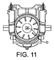
ここで、図7〜図21に関し、特に、カプセルの挿入、収容及び排出に関連する本発明の淹出ユニットの機能について説明する。 Referring now to FIGS. 7-21, the function of the brewing unit of the present invention will be described with particular reference to the insertion, storage and ejection of capsules.
図7〜図9のカプセル挿入位置においては、通路9を十分に長手方向に長いままとするために収容部を互いに引き離し、カプセルが、ケーシングの挿入穴10に挿入された後、一対の顎の摺動面36に沿って案内され、同顎の支持面35上に保持されることを可能にする。この位置において、一対の顎はカプセル保持位置にあり、第1の作動手段47は、係合することにより一対の顎を保持位置にて制止させる。特に、作動手段47のカム部48は、一対の顎の相補形カム部50と係合する。このため、カプセルは挿入中間位置に着座する。挿入中間位置では、カプセルの中心線Oが中心軸線Iと実質的に一致する(又はカプセルのフランジと顎の摺動面との間の遊びによりわずかに傾斜する)。本文脈においては、カプセルは、遠心処理/回転淹出ユニット内でカプセルの中心軸線に沿って高速で回転することになる回転対称な要素として設計されている。遠心処理/回転淹出ユニット内では、キャビティ内においてカプセルの精密な位置を維持し、カプセルの破損及び/又は振動の発生を回避することが重要である。しかしながら、本発明は、非対称なカプセル、及び/又は淹出ユニットが遠心処理/回転式でないシステムに適用してもよい。しかしながら、収容部に対するカプセルの適切な収容及び/又は締め付け具合(tightness)を維持するために、収容部、例えば、キャビティとカプセルの正確な一致は依然として重要である。
In the capsule insertion position of FIGS. 7 to 9, the receptacles are separated from one another in order to keep the
図10〜図12に示されるように、ハンドル57が下げられると、第2の収容部3は第1の収容部2へと強制的に近づけられる。この中間閉鎖段階において、カプセル保持位置における一対の顎の安定性により、カプセル挿入アセンブリはカプセル保持位置に留まる。このため、カプセルは顎同士の間に係合したその中間基準位置に維持され得る。
As shown in FIGS. 10 to 12, when the
第2の収容部3が第1の収容部2に十分に接近する(図13〜図15)につれて、第2の作動手段52が係合することにより一対の顎はカプセル解放位置にて強制的に引き離される。カプセルはもはや一対の顎によって保持されておらず、キャビティ15の縁端に十分に接近しており、第2の収容部のキャビティによって保持されている。この収容部が第1の収容部に対し動き続けるため、カプセルがキャビティ内に収容される。第1の収容部をカプセルに十分に接近させて、収容部がカプセルの周りで閉じる際に穴開け手段、すなわち針29によってカプセルを適切に中央に位置決めし、カプセルを保持することもまた可能である。
As the second container 3 is sufficiently close to the first container 2 (FIGS. 13 to 15), the pair of jaws are forcibly moved in the capsule release position by the engagement of the second actuation means 52. To be separated. The capsule is no longer held by the pair of jaws, but rather close to the edge of the
第2の収容部3が第1の収容部2に向かって更に動くにつれて、カプセルのフランジは第2の収容部の押付縁部16によって押され、その後、第1の収容部の押付縁部17によって押される。淹出ユニットの閉位置において、カプセルの本体はキャビティ15内に収容されており、そのフランジは2つの押付縁部の間で締め付けられている。カプセル挿入アセンブリ32は第2の収容部から離れて十分に引き込まれている。この位置は飲料淹出位置に相当する。概して、抽出遠心処理は、液体注入手段27によりカプセル内に水を供給することによって実施され得る。カプセルはカプセルホルダ22を回転モータにより回転駆動することによって回転させることができる。遠心処理された飲料は回収部18に回収することができ、飲料出口5を通じて排出することができる。
As the second container 3 moves further towards the
飲料調製後、ユニットは、図19〜図21に示されるように、ハンドルにより第2の収容部3を駆動し、第2の収容部3を第1の収容部から長手方向Iに沿って離すことによって再度開かれる。カプセル挿入アセンブリに安定位置(カプセル解放位置)が与えられていることから、一対の顎が開いたままとなることにより、カプセルをカプセル排出手段55によってキャビティから排出し、その後、大きく開いた通路内に落下させることが可能になる。 After the preparation of the beverage, the unit drives the second storage unit 3 with the handle, and separates the second storage unit 3 from the first storage unit along the longitudinal direction I, as shown in FIGS. 19 to 21. Will be reopened. Since the capsule insertion assembly is provided with a stable position (capsule release position), the pair of jaws is kept open, so that the capsule is discharged from the cavity by the capsule discharge means 55, and then the capsule is opened in the wide open passage. Can be dropped.
次の段階において、第2の収容部が更に離れると、カプセル挿入アセンブリは第1の作動手段によって係合され、通路への新たなカプセルの挿入が妨げられる(図7〜図9の状況に戻る)。 In the next step, when the second receptacle is further disengaged, the capsule insertion assembly is engaged by the first actuation means, preventing the insertion of a new capsule into the passage (returning to the situation of FIGS. 7 to 9). ).
Claims (15)
ケーシング(8)と、
前記ケーシングに接続された第1の収容部(2)と、第2の収容部(3)と、を備えるカプセル収容アセンブリであって、前記2つの収容部の間に形成された通路(9)の分だけ前記2つの収容部が互いに離れる距離にあるカプセル挿入位置と、カプセルが前記第1の収容部(2)と前記第2の収容部(3)との間に収容されるカプセル収容位置との間において、前記第2の収容部(3)は、前記第1の収容部に対し長手方向の軸線(I)に沿って動くことができる、カプセル収容アセンブリと、
前記カプセル(4)を中間挿入位置に向かって案内し、前記カプセル(4)を前記中間挿入位置に保持するように配置された一対の顎(33、34)を備えており、前記一対の顎が、重力に反して前記カプセルを保持するための一対の支持面(35)を備えている、カプセル挿入アセンブリ(32)と、を備えており、
前記一対の顎(33、34)は、前記カプセルをカプセル保持位置に保持するのに十分な距離で前記支持面(35)が互いに接近しているカプセル保持位置と、前記一対の顎の前記支持面(35)が前記カプセルをもはや保持しない十分な距離で離れているカプセル解放位置と、の間において動くことができる、
飲料淹出ユニット(1)において、
前記一対の顎(33、34)が、第1の作動手段(47、48、49、50)によって前記カプセル解放位置から前記カプセル保持位置へと動かされ、第2の作動手段(52、53、54)によって前記カプセル保持位置から前記カプセル解放位置へと動かされ、
前記第1及び第2の作動手段(47、48、49;52、53、54)が、前記2つの収容部(2、3)の相対運動のために長手方向の軸線(I)の方向に沿って互いに長手方向の距離を置いて配置されており、もって、淹出後、前記第2の収容部(3)が前記第1の収容部(2)から相対的に離れて、前記2つの収容部が互いに十分に離れ、前記通路(9)を通して前記カプセル(4)を前記カプセル収容アセンブリ(2、3)から取り出すことが可能になると、前記第1の作動手段(47、48、49、50)が前記顎に作用し、前記カプセルが前記収容部によって収容される前に、前記第2の収容部(3)が相対的に前記第1の収容部(2)に向かって動き、前記収容部が互いに十分に接近して、前記収容部(2、3)の少なくとも一方によって前記カプセルを適切に維持する又は保持することが可能になると、前記第2の作動手段(52、53、54)が前記顎に作用するようになっており、
前記第1の収容部(2)及び前記第2の収容部(3)は、前記カプセルを回転駆動させて前記カプセル内部に遠心力を作用させることにより前記カプセルから飲料を抽出させる遠心処理淹出ユニットの少なくとも一部をともに形成していることを特徴とする、飲料淹出ユニット(1)。 A drinking淹出unit (1),
A casing (8);
A capsule receiving assembly comprising a first receiving part (2) connected to said casing and a second receiving part (3), wherein a passage (9) formed between said two receiving parts. capsule housing to be accommodated between the amount corresponding the two housing parts and the capsule insertion position at a distance away from each other, mosquito capsule said first housing portion (2) and said second housing portion (3) of in between positions, the second housing portion (3) is movable along a longitudinal axis (I) over the previous SL first housing portion, and the capsule housing assembly,
A pair of jaws (33, 34) arranged to guide the capsule (4) toward the intermediate insertion position and to hold the capsule (4) at the intermediate insertion position; A capsule insertion assembly (32) comprising a pair of support surfaces (35) for holding said capsule against gravity.
The pair of jaws (33, 34) are in a capsule holding position where the support surfaces (35) are close to each other a sufficient distance to hold the capsule in the capsule holding position, and the support of the pair of jaws. A surface (35) is movable between a capsule release position separated by a sufficient distance that it no longer holds the capsule;
In the beverage brewing unit (1),
The pair of jaws (33, 34) are moved from the capsule release position to the capsule holding position by the first operating means (47, 48, 49, 50), and the second operating means (52, 53, 54) moving from the capsule holding position to the capsule release position,
The first and second actuation means (47, 48, 49; 52, 53, 54) are arranged in the direction of the longitudinal axis (I) for relative movement of the two receiving parts (2, 3). Along a longitudinal distance from each other, so that after brewing, the second storage part (3) is relatively separated from the first storage part (2), When the receptacles are sufficiently separated from each other to allow removal of the capsule (4) from the capsule receiving assembly (2, 3) through the passage (9), the first actuation means (47, 48, 49, 50) acts on the jaw, and before the capsule is received by the receiving part, the second receiving part (3) moves relatively toward the first receiving part (2), The receiving parts are sufficiently close to each other that at least one of the receiving parts (2, 3) Wherein the capsule makes it possible to properly maintain or hold, the second actuating means (52, 53, 54) are adapted to act on the jaw by,
The first accommodating section (2) and the second accommodating section (3) serve to extract the beverage from the capsule by rotating the capsule and applying a centrifugal force to the inside of the capsule. A beverage brewing unit (1), characterized in that at least a part of the unit is formed together .
Applications Claiming Priority (3)
| Application Number | Priority Date | Filing Date | Title |
|---|---|---|---|
| EP14167828.4 | 2014-05-12 | ||
| EP14167828 | 2014-05-12 | ||
| PCT/EP2015/060138 WO2015173124A1 (en) | 2014-05-12 | 2015-05-08 | Beverage brewing unit particularly for machines for preparing beverages from capsules |
Publications (2)
| Publication Number | Publication Date |
|---|---|
| JP2017518778A JP2017518778A (en) | 2017-07-13 |
| JP6671295B2 true JP6671295B2 (en) | 2020-03-25 |
Family
ID=50679950
Family Applications (1)
| Application Number | Title | Priority Date | Filing Date |
|---|---|---|---|
| JP2016560511A Active JP6671295B2 (en) | 2014-05-12 | 2015-05-08 | Beverage brewing unit, especially for machines for preparing beverages from capsules |
Country Status (10)
| Country | Link |
|---|---|
| US (1) | US10448780B2 (en) |
| EP (1) | EP3142526B1 (en) |
| JP (1) | JP6671295B2 (en) |
| CN (1) | CN106132254B (en) |
| AU (1) | AU2015261074B2 (en) |
| CA (1) | CA2941799C (en) |
| ES (1) | ES2784750T3 (en) |
| PT (1) | PT3142526T (en) |
| RU (1) | RU2690146C1 (en) |
| WO (1) | WO2015173124A1 (en) |
Families Citing this family (20)
| Publication number | Priority date | Publication date | Assignee | Title |
|---|---|---|---|---|
| WO2015173124A1 (en) | 2014-05-12 | 2015-11-19 | Nestec S.A. | Beverage brewing unit particularly for machines for preparing beverages from capsules |
| PT3142525T (en) | 2014-05-12 | 2018-07-02 | Nestle Sa | Beverage brewing unit particularly for machines for preparing beverages from capsules |
| EP3393312B1 (en) * | 2015-12-22 | 2020-02-12 | Koninklijke Philips N.V. | Brewing unit for a beverage producing machine and machine containing the brewing unit |
| CA3041722A1 (en) | 2016-11-09 | 2018-05-17 | Pepsico, Inc. | Carbonated beverage makers, methods, and systems |
| JP2020516344A (en) | 2017-04-11 | 2020-06-11 | ソシエテ・デ・プロデュイ・ネスレ・エス・アー | Beverage preparation device provided with beverage discharging means |
| US11877688B2 (en) * | 2017-10-19 | 2024-01-23 | Sgl Italia S.R.L. Con Unico Socio | Brewing device for producing a beverage |
| GB2572030A (en) * | 2018-01-26 | 2019-09-18 | Ne Innovations Ltd | System for filtering liquid |
| IT201800002769A1 (en) * | 2018-02-16 | 2019-08-16 | Ascendo Medienagentur Ag | MACHINE AND METHOD FOR THE PRODUCTION OF BEVERAGES USING SINGLE-DOSE CAPSULES |
| IT201900006838A1 (en) | 2019-05-15 | 2020-11-15 | Ima Spa | Weighing system for a capsule filling machine. |
| CN113712434B (en) * | 2021-08-23 | 2023-09-15 | 深圳安吉尔饮水产业集团有限公司 | Beverage capsule mechanism and beverage preparation system |
| WO2023118246A1 (en) | 2021-12-22 | 2023-06-29 | Société des Produits Nestlé S.A. | Beverage preparation with a flexible outlet valve |
| WO2023118247A1 (en) | 2021-12-22 | 2023-06-29 | Société des Produits Nestlé S.A. | Beverage preparation with simple capsule transfer |
| WO2023118248A1 (en) | 2021-12-22 | 2023-06-29 | Société des Produits Nestlé S.A. | Beverage preparation by centrifugation with reliable capsule transfer |
| WO2023118249A1 (en) | 2021-12-22 | 2023-06-29 | Société des Produits Nestlé S.A. | Beverage preparation by stable capsule centrifugation |
| WO2023118245A1 (en) | 2021-12-22 | 2023-06-29 | Société des Produits Nestlé S.A. | Beverage preparation with compact conditioning chamber |
| WO2023118244A1 (en) | 2021-12-22 | 2023-06-29 | Société des Produits Nestlé S.A. | Beverage preparation with a stable outlet valve |
| WO2023198819A1 (en) | 2022-04-14 | 2023-10-19 | Société des Produits Nestlé S.A. | Centrifugal chamber with capsule opening elements |
| WO2023198821A1 (en) | 2022-04-14 | 2023-10-19 | Société des Produits Nestlé S.A. | Centrifugal beverage chamber with closure fastener |
| WO2023198823A1 (en) * | 2022-04-14 | 2023-10-19 | Société des Produits Nestlé S.A. | Centrifugal chamber with capsule positioning guide |
| CN218588818U (en) * | 2022-09-29 | 2023-03-10 | 珠海横琴鑫润智能制造有限公司 | Capsule beverage brewing device |
Family Cites Families (19)
| Publication number | Priority date | Publication date | Assignee | Title |
|---|---|---|---|---|
| EP1495702A1 (en) | 2003-07-10 | 2005-01-12 | Nestec S.A. | Device for the extraction of a cartridge |
| US20080096385A1 (en) * | 2006-09-27 | 2008-04-24 | Hynix Semiconductor Inc. | Slurry composition for forming tungsten pattern and method for manufacturing semiconductor device using the same |
| ITFI20070028A1 (en) * | 2007-02-07 | 2008-08-08 | Saeco Ipr Ltd | INFUSION DEVICE FOR THE PREPARATION OF DRINKS FROM SINGLE-DOSE CAPSULES WITH A CAPSULES CENTERING DEVICE. |
| PL2152608T3 (en) * | 2007-06-05 | 2013-05-31 | Nestec Sa | Capsule and method for preparing a food liquid by centrifugation |
| CN100544647C (en) | 2007-06-15 | 2009-09-30 | 宁波三A集团电器有限公司 | Automatically the mechanism that comes off of coffee bag in coffee maker |
| EP2070454B1 (en) * | 2007-12-12 | 2015-07-15 | Nestec S.A. | Beverage production machines comprising a plurality of core units |
| PL2679120T3 (en) | 2008-03-14 | 2017-07-31 | Mocoffee Ag | Appliance and capsule for preparing a beverage |
| JP2010040428A (en) * | 2008-08-07 | 2010-02-18 | Smk Corp | Switch |
| EP2337479B1 (en) * | 2008-09-18 | 2015-11-11 | Koninklijke Philips N.V. | Infusion device for coffee machines and the like |
| DE102009052521A1 (en) | 2009-11-11 | 2011-05-12 | K System Gmbh | Brewing device for extracting portion capsule to produce cappuccino, has holding unit for holding portion capsule in loading position of closure element and pivotable around pivot axis that extends parallel to axial direction |
| IT1400432B1 (en) | 2010-06-01 | 2013-05-31 | Lavazza Luigi Spa | INFUSION SYSTEM FOR A DRINK PREPARATION MACHINE. |
| PT2592977T (en) | 2010-07-16 | 2022-03-14 | Nestle Sa | Device for preparing a beverage by centrifugation |
| JP5876053B2 (en) | 2010-09-28 | 2016-03-02 | ネステク ソシエテ アノニム | Device and method for recovering capsules from beverage production equipment |
| IT1403428B1 (en) | 2010-12-24 | 2013-10-17 | Lavazza Luigi Spa | INFUSION SYSTEM FOR A DRINK PREPARATION MACHINE |
| EP3381337A1 (en) | 2011-03-14 | 2018-10-03 | Nestec S.A. | Automatic beverage machine |
| ITMI20110773A1 (en) * | 2011-05-06 | 2012-11-07 | Studio Polillo S A S Di Corrente A & C | EQUIPMENT FOR THE PREPARATION OF A BEVERAGE STARTING FROM POWDER MATERIALS CONTAINED IN A SEALED CAPSULE. |
| EP2717748B1 (en) * | 2011-06-09 | 2015-07-22 | Luigi Lavazza S.p.A. | Delivery assembly for machines for preparing liquid products via cartridges |
| PT3142525T (en) * | 2014-05-12 | 2018-07-02 | Nestle Sa | Beverage brewing unit particularly for machines for preparing beverages from capsules |
| WO2015173124A1 (en) | 2014-05-12 | 2015-11-19 | Nestec S.A. | Beverage brewing unit particularly for machines for preparing beverages from capsules |
-
2015
- 2015-05-08 WO PCT/EP2015/060138 patent/WO2015173124A1/en active Application Filing
- 2015-05-08 CN CN201580016206.6A patent/CN106132254B/en active Active
- 2015-05-08 EP EP15723874.2A patent/EP3142526B1/en active Active
- 2015-05-08 AU AU2015261074A patent/AU2015261074B2/en active Active
- 2015-05-08 ES ES15723874T patent/ES2784750T3/en active Active
- 2015-05-08 JP JP2016560511A patent/JP6671295B2/en active Active
- 2015-05-08 RU RU2016148323A patent/RU2690146C1/en active
- 2015-05-08 PT PT157238742T patent/PT3142526T/en unknown
- 2015-05-08 CA CA2941799A patent/CA2941799C/en active Active
- 2015-05-08 US US15/302,758 patent/US10448780B2/en active Active
Also Published As
| Publication number | Publication date |
|---|---|
| CA2941799C (en) | 2022-07-05 |
| CA2941799A1 (en) | 2015-11-19 |
| EP3142526A1 (en) | 2017-03-22 |
| CN106132254B (en) | 2020-06-09 |
| ES2784750T3 (en) | 2020-09-30 |
| WO2015173124A1 (en) | 2015-11-19 |
| US20170027371A1 (en) | 2017-02-02 |
| AU2015261074B2 (en) | 2019-06-27 |
| RU2690146C1 (en) | 2019-05-30 |
| CN106132254A (en) | 2016-11-16 |
| EP3142526B1 (en) | 2020-03-18 |
| US10448780B2 (en) | 2019-10-22 |
| AU2015261074A1 (en) | 2016-08-11 |
| PT3142526T (en) | 2020-06-19 |
| JP2017518778A (en) | 2017-07-13 |
Similar Documents
| Publication | Publication Date | Title |
|---|---|---|
| JP6671295B2 (en) | Beverage brewing unit, especially for machines for preparing beverages from capsules | |
| JP6640734B2 (en) | Beverage brewing unit, especially for machines for preparing beverages from capsules | |
| TWI403442B (en) | Dispositif pour 1'extraction d'une capsule | |
| US9486106B2 (en) | Device and method for retrieving a capsule from a beverage production apparatus | |
| EP2654528B1 (en) | An infusion apparatus for a machine for preparing beverages | |
| US20110265660A1 (en) | An infusion assembly for a machine for the preparation of beverages | |
| JP2015534486A (en) | Beverage machine equipped with ingredient capsule attachment device | |
| JP6377069B2 (en) | Apparatus for preparing a beverage from a capsule using a closure system comprising two closure stages | |
| EP2915465A1 (en) | Beverage production device for receiving a capsule for the preparation of a beverage | |
| US10537201B2 (en) | Beverage production system using capsules |
Legal Events
| Date | Code | Title | Description |
|---|---|---|---|
| A621 | Written request for application examination |
Free format text: JAPANESE INTERMEDIATE CODE: A621 Effective date: 20180502 |
|
| A977 | Report on retrieval |
Free format text: JAPANESE INTERMEDIATE CODE: A971007 Effective date: 20190403 |
|
| A131 | Notification of reasons for refusal |
Free format text: JAPANESE INTERMEDIATE CODE: A131 Effective date: 20190514 |
|
| A711 | Notification of change in applicant |
Free format text: JAPANESE INTERMEDIATE CODE: A712 Effective date: 20190614 |
|
| A521 | Request for written amendment filed |
Free format text: JAPANESE INTERMEDIATE CODE: A523 Effective date: 20190809 |
|
| TRDD | Decision of grant or rejection written | ||
| A01 | Written decision to grant a patent or to grant a registration (utility model) |
Free format text: JAPANESE INTERMEDIATE CODE: A01 Effective date: 20200204 |
|
| A61 | First payment of annual fees (during grant procedure) |
Free format text: JAPANESE INTERMEDIATE CODE: A61 Effective date: 20200303 |
|
| R150 | Certificate of patent or registration of utility model |
Ref document number: 6671295 Country of ref document: JP Free format text: JAPANESE INTERMEDIATE CODE: R150 |
|
| R250 | Receipt of annual fees |
Free format text: JAPANESE INTERMEDIATE CODE: R250 |
|
| R250 | Receipt of annual fees |
Free format text: JAPANESE INTERMEDIATE CODE: R250 |