EP3140595B1 - Verfahren und vorrichtung zur unterstützung der verbrennung von brennstoff - Google Patents
Verfahren und vorrichtung zur unterstützung der verbrennung von brennstoff Download PDFInfo
- Publication number
- EP3140595B1 EP3140595B1 EP15723415.4A EP15723415A EP3140595B1 EP 3140595 B1 EP3140595 B1 EP 3140595B1 EP 15723415 A EP15723415 A EP 15723415A EP 3140595 B1 EP3140595 B1 EP 3140595B1
- Authority
- EP
- European Patent Office
- Prior art keywords
- fuel
- air
- plasma generator
- fuel nozzle
- combustion chamber
- Prior art date
- Legal status (The legal status is an assumption and is not a legal conclusion. Google has not performed a legal analysis and makes no representation as to the accuracy of the status listed.)
- Active
Links
- 239000000446 fuel Substances 0.000 title claims description 285
- 238000002485 combustion reaction Methods 0.000 title claims description 171
- 238000000034 method Methods 0.000 title claims description 12
- 239000000203 mixture Substances 0.000 claims description 95
- 238000002156 mixing Methods 0.000 claims description 47
- 238000004891 communication Methods 0.000 claims description 33
- 239000012530 fluid Substances 0.000 claims description 21
- 230000004888 barrier function Effects 0.000 claims description 4
- 238000010494 dissociation reaction Methods 0.000 claims description 4
- 230000005593 dissociations Effects 0.000 claims description 4
- 238000010891 electric arc Methods 0.000 claims description 2
- 210000002381 plasma Anatomy 0.000 description 144
- 238000006243 chemical reaction Methods 0.000 description 20
- 239000000047 product Substances 0.000 description 13
- 230000006641 stabilisation Effects 0.000 description 9
- 238000011105 stabilization Methods 0.000 description 9
- IJGRMHOSHXDMSA-UHFFFAOYSA-N Atomic nitrogen Chemical compound N#N IJGRMHOSHXDMSA-UHFFFAOYSA-N 0.000 description 4
- 239000007789 gas Substances 0.000 description 4
- 238000000429 assembly Methods 0.000 description 3
- 230000000712 assembly Effects 0.000 description 3
- 230000007423 decrease Effects 0.000 description 3
- 230000003247 decreasing effect Effects 0.000 description 3
- 230000005684 electric field Effects 0.000 description 3
- 238000002347 injection Methods 0.000 description 3
- 239000007924 injection Substances 0.000 description 3
- 238000004519 manufacturing process Methods 0.000 description 3
- 239000000463 material Substances 0.000 description 3
- 230000007246 mechanism Effects 0.000 description 3
- 239000002245 particle Substances 0.000 description 3
- 230000008569 process Effects 0.000 description 3
- 239000000376 reactant Substances 0.000 description 3
- ATUOYWHBWRKTHZ-UHFFFAOYSA-N Propane Chemical compound CCC ATUOYWHBWRKTHZ-UHFFFAOYSA-N 0.000 description 2
- 125000004429 atom Chemical group 0.000 description 2
- 230000015572 biosynthetic process Effects 0.000 description 2
- 230000000694 effects Effects 0.000 description 2
- 230000005284 excitation Effects 0.000 description 2
- 238000005755 formation reaction Methods 0.000 description 2
- VNWKTOKETHGBQD-UHFFFAOYSA-N methane Chemical compound C VNWKTOKETHGBQD-UHFFFAOYSA-N 0.000 description 2
- 229910052757 nitrogen Inorganic materials 0.000 description 2
- 230000003647 oxidation Effects 0.000 description 2
- 238000007254 oxidation reaction Methods 0.000 description 2
- 239000004215 Carbon black (E152) Substances 0.000 description 1
- MYMOFIZGZYHOMD-UHFFFAOYSA-N Dioxygen Chemical compound O=O MYMOFIZGZYHOMD-UHFFFAOYSA-N 0.000 description 1
- 230000009471 action Effects 0.000 description 1
- 230000002411 adverse Effects 0.000 description 1
- 230000008033 biological extinction Effects 0.000 description 1
- 239000000919 ceramic Substances 0.000 description 1
- 230000008859 change Effects 0.000 description 1
- 239000007795 chemical reaction product Substances 0.000 description 1
- 230000005495 cold plasma Effects 0.000 description 1
- 238000000354 decomposition reaction Methods 0.000 description 1
- 230000004069 differentiation Effects 0.000 description 1
- 238000010790 dilution Methods 0.000 description 1
- 239000012895 dilution Substances 0.000 description 1
- 230000002708 enhancing effect Effects 0.000 description 1
- 229930195733 hydrocarbon Natural products 0.000 description 1
- 150000002430 hydrocarbons Chemical class 0.000 description 1
- 239000001257 hydrogen Substances 0.000 description 1
- 229910052739 hydrogen Inorganic materials 0.000 description 1
- 125000004435 hydrogen atom Chemical class [H]* 0.000 description 1
- 238000011065 in-situ storage Methods 0.000 description 1
- 230000000977 initiatory effect Effects 0.000 description 1
- 239000012212 insulator Substances 0.000 description 1
- 230000003993 interaction Effects 0.000 description 1
- 239000003350 kerosene Substances 0.000 description 1
- 238000005511 kinetic theory Methods 0.000 description 1
- 239000007788 liquid Substances 0.000 description 1
- 230000010355 oscillation Effects 0.000 description 1
- 230000037361 pathway Effects 0.000 description 1
- 239000001294 propane Substances 0.000 description 1
- 230000036632 reaction speed Effects 0.000 description 1
- 238000002407 reforming Methods 0.000 description 1
- 230000004044 response Effects 0.000 description 1
- 238000000926 separation method Methods 0.000 description 1
- 239000000243 solution Substances 0.000 description 1
- 238000009987 spinning Methods 0.000 description 1
- 239000007921 spray Substances 0.000 description 1
- 230000000087 stabilizing effect Effects 0.000 description 1
- 238000011144 upstream manufacturing Methods 0.000 description 1
- 230000000007 visual effect Effects 0.000 description 1
Images


Classifications
-
- F—MECHANICAL ENGINEERING; LIGHTING; HEATING; WEAPONS; BLASTING
- F23—COMBUSTION APPARATUS; COMBUSTION PROCESSES
- F23R—GENERATING COMBUSTION PRODUCTS OF HIGH PRESSURE OR HIGH VELOCITY, e.g. GAS-TURBINE COMBUSTION CHAMBERS
- F23R3/00—Continuous combustion chambers using liquid or gaseous fuel
- F23R3/28—Continuous combustion chambers using liquid or gaseous fuel characterised by the fuel supply
- F23R3/286—Continuous combustion chambers using liquid or gaseous fuel characterised by the fuel supply having fuel-air premixing devices
-
- F—MECHANICAL ENGINEERING; LIGHTING; HEATING; WEAPONS; BLASTING
- F02—COMBUSTION ENGINES; HOT-GAS OR COMBUSTION-PRODUCT ENGINE PLANTS
- F02C—GAS-TURBINE PLANTS; AIR INTAKES FOR JET-PROPULSION PLANTS; CONTROLLING FUEL SUPPLY IN AIR-BREATHING JET-PROPULSION PLANTS
- F02C7/00—Features, components parts, details or accessories, not provided for in, or of interest apart form groups F02C1/00 - F02C6/00; Air intakes for jet-propulsion plants
- F02C7/26—Starting; Ignition
- F02C7/264—Ignition
- F02C7/266—Electric
-
- F—MECHANICAL ENGINEERING; LIGHTING; HEATING; WEAPONS; BLASTING
- F23—COMBUSTION APPARATUS; COMBUSTION PROCESSES
- F23C—METHODS OR APPARATUS FOR COMBUSTION USING FLUID FUEL OR SOLID FUEL SUSPENDED IN A CARRIER GAS OR AIR
- F23C99/00—Subject-matter not provided for in other groups of this subclass
- F23C99/001—Applying electric means or magnetism to combustion
-
- F—MECHANICAL ENGINEERING; LIGHTING; HEATING; WEAPONS; BLASTING
- F23—COMBUSTION APPARATUS; COMBUSTION PROCESSES
- F23R—GENERATING COMBUSTION PRODUCTS OF HIGH PRESSURE OR HIGH VELOCITY, e.g. GAS-TURBINE COMBUSTION CHAMBERS
- F23R3/00—Continuous combustion chambers using liquid or gaseous fuel
- F23R3/02—Continuous combustion chambers using liquid or gaseous fuel characterised by the air-flow or gas-flow configuration
- F23R3/04—Air inlet arrangements
- F23R3/10—Air inlet arrangements for primary air
- F23R3/12—Air inlet arrangements for primary air inducing a vortex
- F23R3/14—Air inlet arrangements for primary air inducing a vortex by using swirl vanes
-
- F—MECHANICAL ENGINEERING; LIGHTING; HEATING; WEAPONS; BLASTING
- F23—COMBUSTION APPARATUS; COMBUSTION PROCESSES
- F23C—METHODS OR APPARATUS FOR COMBUSTION USING FLUID FUEL OR SOLID FUEL SUSPENDED IN A CARRIER GAS OR AIR
- F23C2900/00—Special features of, or arrangements for combustion apparatus using fluid fuels or solid fuels suspended in air; Combustion processes therefor
- F23C2900/99005—Combustion techniques using plasma gas
-
- F—MECHANICAL ENGINEERING; LIGHTING; HEATING; WEAPONS; BLASTING
- F23—COMBUSTION APPARATUS; COMBUSTION PROCESSES
- F23R—GENERATING COMBUSTION PRODUCTS OF HIGH PRESSURE OR HIGH VELOCITY, e.g. GAS-TURBINE COMBUSTION CHAMBERS
- F23R2900/00—Special features of, or arrangements for continuous combustion chambers; Combustion processes therefor
- F23R2900/00008—Combustion techniques using plasma gas
-
- F—MECHANICAL ENGINEERING; LIGHTING; HEATING; WEAPONS; BLASTING
- F23—COMBUSTION APPARATUS; COMBUSTION PROCESSES
- F23R—GENERATING COMBUSTION PRODUCTS OF HIGH PRESSURE OR HIGH VELOCITY, e.g. GAS-TURBINE COMBUSTION CHAMBERS
- F23R2900/00—Special features of, or arrangements for continuous combustion chambers; Combustion processes therefor
- F23R2900/00009—Using plasma torches for igniting, stabilizing, or improving the combustion process
Definitions
- This disclosure relates to an apparatus and method for assisting with the combustion of fuel and, more particularly, to applying a plasma field to an air-fuel mixture to at least partially ionize and/or dissociate the air-fuel mixture.
- Plasma is an electronically exited state of matter in which the electrons from individual atoms are stripped via electrical interactions with the energy source and by collisions with other energized particles.
- Plasmas are useful at speeding up reactions by transferring the plasma's energy into the vibration translational or rotational energy of reactants.
- Plasma assisted reactions usually include reforming the reactants. Reactants are reformed by the breaking of bonds and the production of active radicals.
- the velocity of the air at the entrance of the combustion chamber is around 150 meters per second depending on the thrust rating of the engine and the atmospheric conditions.
- the speed of the velocity air entering the combustion chamber is of concern because this -150 m/s flow velocity is much higher than the flame speed of a kerosene air flame, and may make it difficult to sustain combustion.
- engine designers generally will reduce both the velocity and pressure of the incoming air before attempting to initiate a combustion reaction with that air.
- the combustion chamber often will be provided with geometries, which impede the airflow and force it to reduce its velocity.
- Examples of these geometries are swirl vanes and dilution holes, as well as the shape of the combustion chamber itself.
- the chamber can be shaped to create an eddy-an area of lower pressure in which combustion is permitted to occur--albeit at the expense of a pressure drop across the combustion chamber. According to basic thermodynamics, this pressure drop in the combustion chamber will reduce efficiency of combustion. As a result of this compromise in even the most efficient jet engines, roughly 10% of the input fuel is left un-burnt.
- US 2005/044854 relates to an air/fuel injection system having cold plasma generating means;
- US 2009/165436 relates to a pre-mixed, pre-swirled plasma-assisted pilot Including a swirler mechanism;
- US 2011/126548 relates to a method and device for the combustion of hydrocarbon-containing fuels.
- a swirler assembly is provided, the swirler assembly having at least one swirler assembly inlet and at least one swirler assembly outlet longitudinally separated from the at least one swirler assembly inlet by a swirler body defining a swirler assembly inner wall.
- the swirler body includes two rings of swirler vanes, wherein one ring of the swirler vanes extends laterally inwardly from the swirler assembly inner wall and the other ring of swirler vanes extends laterally outwardly from the swirler assembly inner wall.
- a fuel nozzle is provided. The fuel nozzle has a fuel nozzle mixing chamber, a fuel nozzle air inlet, and a fuel nozzle air outlet.
- the fuel nozzle mixing chamber is in fluid communication with both a fuel nozzle fuel reservoir and the fuel nozzle air inlet.
- the fuel nozzle air inlet allows air from the swirler assembly outlet to flow into the fuel nozzle.
- Fuel from the fuel nozzle fuel reservoir is directed into the fuel nozzle mixing chamber and, inside the fuel nozzle mixing chamber, the fuel combines with air therein to form a fuel-air mixture.
- At least one plasma generator is located at least partially within the fuel nozzle. The plasma generator at least partially ionizes and/or dissociates the fuel-air mixture to generate an at least one of an at least partially ionized air-fuel mixture and an at least partially dissociated air-fuel mixture ("at least partially air-fuel mixture”) via a plasma generator discharge.
- a combustion chamber has a combustion chamber inlet in fluid communication with the swirler assembly outlet.
- the combustion chamber has a combustion chamber outlet.
- the combustion chamber inlet and outlet are longitudinally separated by a combustion chamber internal volume including an R/R zone, a main flame, and a pilot flame.
- the combustion chamber inlet admits the at least partially I/D air-fuel mixture created by the plasma generator into the combustion chamber internal volume.
- the swirler assembly and the at least one plasma generator are arranged such that combustion air enters the swirler assembly inlet, flows through the swirler body, and exits the swirler body through the swirler assembly outlet with aerodynamic swirl having a rotational axis substantially parallel to a longitudinal axis of the plasma generator.
- the combustion air flows from the wider assembly outlet into the combustion chamber internal volume through the combustion chamber inlet.
- Aerodynamic swirl imparts a rotation to the at least partially I/D fuel-air mixture that contributes to a quasi-spatially uniform discharge of the at least partially I/D fuel-air mixture from the plasma generator.
- Combustion of the at least partially I/D air-fuel mixture with the combustion air occurs at least partially within the combustion chamber internal volume to responsively produce products.
- the products exit the combustion chamber internal volume through the combustion chamber outlet.
- An apparatus in another aspect of the present invention, a method for assisting with the combustion of fuel is described.
- An apparatus is provided.
- the apparatus Includes a swirler assembly having at least one swirler assembly inlet and at least one swirler assembly outlet longitudinally separated from the at least one swirler assembly inlet by a swirler body defining a swirler assembly inner wall.
- the swirler body includes two rings of swirler vanes, wherein one ring of the swirler vanes extends laterally inwardly from the swirler assembly inner wall and the other ring of swirler vanes extends laterally outwardly from the swirler assembly inner wall.
- the apparatus includes a fuel nozzle, having a fuel nozzle mixing chamber, a fuel nozzle air inlet, and a fuel nozzle air outlet.
- the fuel nozzle mixing chamber is in fluid communication with both a fuel nozzle fuel reservoir and the fuel nozzle air inlet.
- the fuel nozzle air inlet allows air from the swirler assembly outlet to flow into the fuel nozzle.
- At least one plasma generator is located at least partially within the fuel nozzle.
- a combustion chamber has a combustion chamber inlet in fluid communication with the swirler assembly outlet.
- the combustion chamber has a combustion chamber outlet.
- the combustion chamber inlet and outlet are longitudinally separated by a combustion chamber internal volume.
- the combustion chamber internal volume includes an R/R zone, a main flame, and a pilot flame.
- Fuel is provided to the fuel nozzle mixing chamber from the fuel nozzle fuel reservoir.
- a fuel-air mixture is created by combining fuel and air within the fuel nozzle mixing chamber.
- a plasma field is created with a plasma generator located at least partially within the fuel nozzle.
- a plasma generator located at least partially within the fuel nozzle.
- at least one of an at least partially ionized air-fuel mixture and an at least partially dissociated air-fuel mixture (“at least partially I/D air-fuel mixture”) is created from at least a portion of the fuel air mixture.
- Aerodynamic swirl imparts a rotation to the at least partially I/D fuel-air mixture, the rotation being oriented substantially about a rotational axis substantially parallel to a longitudinal axis of the plasma generator, the rotation contributing to a quasi-spatially uniform discharge of the at least partially I/D fuel-air mixture from the plasma generator.
- At least a portion of the fuel-air mixture is combusted in the combustion chamber with the plasma field generated from the at least partially I/D air-fuel mixture to produce products.
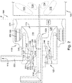
- Figs. 1-2 depict an apparatus 100 for assisting with the combustion of fuel.
- the description herein presumes that the apparatus 100 Is being used as part of a jet engine; but the apparatus 100 may also or instead be used in a gas turbine or any other suitable use application.
- the apparatus 100 includes a swirler assembly 102, which Includes at least one swirler assembly Inlet 104 longitudinally separated from at least one swirler assembly outlet 106 by a swirler body 107 defining a swirler body inner wall 108.
- the term "longitudinal” Is used herein to reference a direction substantially parallel to longitudinal axis "LO"-e.g., the left-right direction in the orientation of Figs. 1-2 .
- the swirler assembly 102 when present, assists combustion air to enter into the apparatus 100 and attain a desired flow direction.
- the swirler assembly 102 accepts combustion air from an ambient source through a swirler assembly inlet 104. The combustion air then travels through the swirler body 107 and exits the swirler assembly 102 through the swirler assembly outlet 106.
- the swirler assembly 102 includes at least one swirler vane 136 for imparting a helical direction to the combustion air. At least one swirler vane 136 extends in a direction laterally inward and laterally outward from the swirler assembly inner wall 108 (whether or not the "fin"-shaped structure forming the swirler vane 136 is itself cantilevered directly from the swirler assembly inner wall 108).
- the term "lateral” is used herein to indicate a direction in a plane substantially perpendicular to the longitudinal direction LO-i.e., into and out of the plane of the paper in the orientation of Figs. 1-2 .
- the swirler vane(s) 136 serves to help impart a helical aspect (A.K.A.. "angular momentum”) to the flow direction of the combustion air through the swirler body 107 and from the swirler assembly outlet 106.
- the apparatus 100 may include more than one swirler assembly 102.
- the orientation of the swirler assemblies 102 may be configured to provide any desired directional change upon the flow path of the combustion air.
- Combustion air may pass through multiple swirler assemblies 102.
- the combustion air could pass through a first swirler assembly 102 and then from there into a second swirler assembly (not shown) and/or through two concentric swirler assemblies as to impart either a co-rotating or counter-helical aspect to the flow, as desired.
- the swirler assembly 102 may include several swirler vanes 136 arranged in any suitable pattern or patterns, such as, but not limited to, a concentric circle pattern. Furthermore, the swirler vanes 136 of a single swirler assembly 102 may be arranged in differing patterns. For example, the swirler vanes 136 may be placed at different angles from one another with respect to the longitudinal axis in order to modify the helical direction of the combustion air in a desired manner. When multiple swirler vanes 136 are used, the swirler assembly 102 may also include an annular flow separator 144. The annular flow separator 144. when present, may aid in changing the path of the combustion air in a desired manner.
- the apparatus 100 further includes a fuel nozzle 118.
- the fuel nozzle 118 contains a fuel nozzle mixing chamber 110.
- the fuel nozzle mixing chamber 110 contains a fuel nozzle air inlet 112 and a fuel nozzle air outlet 114.
- the fuel nozzle mixing chamber 110 is in fluid communication with both the fuel nozzle air inlet 112 and a fuel nozzle fuel reservoir 116, from which fuel, which may be any suitable liquid and/or gaseous fuel (e.g., methane. Jet-A, or the like), is directed into the fuel nozzle mixing chamber 110.
- the fuel nozzle air inlet 112 allows air (e.g., the swirling or helically-directed air from the swirler assembly outlet 106, or any other air.
- a fuel-air mixture then forms in the fuel nozzle mixing chamber 110 as the fuel is dispersed into the helically flowing combustion air which was received into the fuel nozzle mixing chamber 110 from the swirler assembly 102.
- Combustion air may enter the fuel nozzle mixing chamber 110 at the same or different times as does the fuel.
- the apparatus 100 may take on different geometries for desired performance, and an apparatus 100 having a particular configuration for a desired result may be provided by one of ordinary skill in the art of fluid dynamics and gas turbine combustor design.
- Fuel and air are mixed within the fuel nozzle mixing chamber 110 at least in part as a result of the helical or swirling flow direction of the combustion air that enters the fuel nozzle mixing chamber 110. When the fuel and air are mixed, a substantially homogenous air-fuel mixture is created.
- a plasma generator 120 located at least partially within the fuel nozzle 118 is a plasma generator 120.
- the plasma generator 120 in use, creates a plasma discharge (shown schematically as plasma generator discharge 138 throughout the Figures) that is in electrical communication with at least a portion of the fuel nozzle 118, as shown in Fig. 3 .
- the creation of the plasma generator discharge 138 at or near the air-fuel mixture partially ionizes and/or dissociates the fuel-air mixture to create a partially ionized and/or dissociated air-fuel mixture (hereafter referenced as an "at least partially I/D air-fuel mixture”), as will be discussed below in more detail.
- a flame is, after all, a chemical reaction
- the speed of the reaction can be described in terms of the kinetics of the exothermic oxidation of the fuel (e.g., propane).
- the fuel e.g., propane
- increasing the temperature of a system increases the average kinetic energy of the individual molecules.
- An increase in the kinetic energy of the molecules in turn yields more effective collisions. Therefore, increasing the temperature of a chemical reaction will increase the rate at which that reaction proceeds.
- the high temperatures of plasma, as well as the high-energy particles created may be able to aid with enhancing reaction speed to reduce the amount of un-burnt fuel in an engine and solve other combustion challenges such as lean blow off extension.
- Branch chain reactions with active radicals may be the mechanism for flame propagation. Therefore, for plasma to affect a flame, the discharge should have a high degree of volumetric excitation-i.e., a large volume of gas should be excited by the plasma, and the radicals/excited species generated by the plasma should be able to make it into an appropriate part of the combustion engine (e.g., a reaction zone, a recirculation zone, an R/R zone, a combustion chamber, any combination thereof, or any other suitable area) before they are quenched.
- the injection of plasma Into a combustion engine could increase the flame speed of the fuel and air mixture thereby decreasing the residence time needed for complete combustion.
- Plasma since plasma has the potential to increase flame speed, higher molecular weight fuels with greater energy densities could be used. Usually, higher molecular weight fuels are not used due to a penalty in the rate of combustion. Plasma-assisted reactions could substantially reduce the combustion rate penalty associated with higher molecular weight fuels as well as provide for greater flexibility in combusting fuels with varying Wobbe numbers.
- plasma has the ability to influence the kinetics of a reaction and shorten ignition time, plasma can increase flammability limits, thereby allowing mixtures with equivalence values ⁇ 1 (i.e., lean mixtures in which there is less fuel present than the stoichiometric ideal) to stabilize. This translates into fuel savings, decreased emissions, and a decrease in operating costs for an engine using such plasma-assisted combustion techniques.
- This homogeneous treatment is achieved in the apparatus 100 through creating a substantially homogenous air-fuel mixture within the fuel nozzle mixing chamber 110 and generating plasma at or near the homogenous air-fuel mixture.
- the plasma may at least partially ionize and/or at least partially dissociate the air-fuel mixture.
- the process of ionization is achieved when an electric field excites electrons within the fuel molecule so much that the excitation results in either the gain or loss of an electron by/from that molecule. Further ionization may proceed via further excitation, direct electron impact, third body collisions, or other pathways.
- Dissociation is achieved when the energy provided by plasma causes a partial split fuel molecule.
- This split may result in the separation of smaller atoms, like hydrogen, and the creation of free radicals or other activated states.
- the above described process, or portions thereof, results in the creation of an at least partially I/D air-fuel mixture using the plasma generator 120 and other components of the apparatus 100.
- the plasma generator 120 may be any device capable of generating plasma. These devices include, but are not limited to, a nanosecond pulsed plasma generator, a dielectric barrier discharge plasma generator, a radiofrequency discharge plasma generator, a laser plasma generator, a microwave plasma generator, a gliding arc plasma generator, or any combination thereof.
- the apparatus 100 may include multiple plasma generators 120. which may be the same or different types of plasma generator 120 and may operate simultaneously or in any desired sequence
- the plasma generator discharge 138 may be at least one of a gliding arc discharge, a streamer discharge, a dielectric barrier discharge, an RF discharge, and a nanosecond pulsed discharge. It is contemplated that the apparatus 100, at any given time, may employ more than one type of plasma generator discharge 138.
- the apparatus 100 also includes a combustion chamber, shown schematically at 122 in Fig 1 .
- the combustion chamber 122 contains a combustion chamber inlet 124 in fluid communication with at least one of the fuel nozzle air outlet 114 and the swirler assembly outlet 106.
- the combustion chamber inlet 124 admits the at least partially I/D air-fuel mixture from the plasma generator 120 into a combustion chamber internal volume 128.
- the combustion chamber 122 is further defined by a combustion chamber outlet 126 which is longitudinally separated from the combustion chamber inlet 124 by the combustion chamber internal volume 128.
- the combustion chamber outlet 126 allows the products from reactions that take place within the combustion chamber 122 to exit the combustion chamber 122.
- combustion of the at least partially I/D air-fuel mixture with the combustion air may occur at least partially within the combustion chamber internal volume 128 to responsively produce products, and the products exit the combustion chamber internal volume 128 through the combustion chamber outlet 126.
- the combustion chamber inlet 124 and combustion chamber outlet 126 at least partially define the combustion chamber internal volume 128.
- the combustion chamber internal volume 128 contains an R/R zone 130.
- R/R zone is used herein to reference a volume within the combustion chamber 122, just downstream from the plasma generator discharge 138. in which reactions and/or recirculation are taking place.
- reaction zone is generally used to indicate the entire volume within which reactions are taking place.
- recirculation zone' is generally used in the art to describe a pattern of flow which reverses and brings combustion products back to the flame; the recirculation zone is located downstream of the plasma disk, and is substantially inside the reaction zone.
- the combustion chamber internal volume 128 may further include a main flame and a pilot flame, shown schematically at 132 and 134, respectively.
- the R/R zone 130 allows combustion products to proceed toward at least one of the main flame 132 and the pilot flame 134 thereby providing stabilization
- the R/R zone 130 will be now be briefly discussed.
- At least a portion of the at least partially I/D air-fuel mixture enters the combustion chamber 122 by first passing into R/R zone 130. Within this R/R zone 130. fuel and air are further mixed to provide a more homogenous solution. This R/R zone 130 may also be in direct fluid communication with the fuel reservoir 116. The additional fuel provided to the air-fuel mixture in the R/R zone 130 may or may not become partially ionized The plasma generator 120 may further ionize and/or dissociate the air-fuel mixture by creating a plasma generator discharge 138 that extends into the combustion chamber 122 such that radicals and activated particles are generated sufficiently close to the R/R zone 130 so as to provide desired flame stabilization.
- the R/R zone 130 will tend to bring combustion products back to the base of at least one of the main flame 132 and the pilot flame 134. providing stabilization in an area within a desired proximity to the plasma generator discharge 138.
- the fuel that entered the R/R zone 130 but did not enter the fuel nozzle mixing chamber 110 may become ionized within the combustion chamber 122.
- the fuel and air are premixed, and this air-fuel mixture flows into the combustion chamber 122 where combustion starts at the beginning of the flame front (the start of the R/R zone 130).
- Plasma may be used to create the at least partially I/D air-fuel mixture anytime between the premixing and the R/R zone 130.
- the R/R zone 130 brings hot combustion products (mainly from the pilot flame 134) back to the base of the main flame 132 to provide stabilization.
- the R/R zone 130 is created due to forces imparted on the fluids inside the combustion chamber 122 by aerodynamic swirl, the pilot flame 134, the main flame 134 and the at least partially I/D air-fuel mixture itself
- the combustion chamber internal volume 128 further serves as the location for combustion reactions. These combustion reactions are facilitated by the at least partially I/D air-fuel mixture coming into contact with at least one of the main flame 132 and pilot flame 134. The combustion of the at least partially I/D air-fuel mixture then produces reaction products. These products are then directed to exit the combustion chamber 122 through the combustion chamber outlet 126, producing the desired thrust forces from the engine.
- the plasma generator 120 may include an electrode 140 extending substantially longitudinally from a remaining portion of the plasma generator to terminate, spaced apart from the remaining portion of the plasma generator, at an electrode free end 142.
- the shape of the electrode free end 142 may vary for different use environments of the apparatus 100.
- the electrode 140 may have a rounded, pointed, or blunt electrode free end 142 capable of generating various types of plasma generator discharges 138 as desired by one of ordinary skill in the art to create an electric field having a desired strength, shape, or other property for a particular use environment
- the length of the electrode's 140 protrusion from the remaining portion of the plasma generator may differ for different use environments of the apparatus 100.
- the electrode 140 may be configured such that the entire length of the electrode 140. including the electrode free end 142, is wholly located within the fuel nozzle mixing chamber 110.
- the electrode 140 is shown in a configuration wherein the electrode free end 142 is substantially located with the lateral plane P, which is the lateral plane substantially formed by the outermost perimeter/rim of the fuel nozzle air outlet 114.
- the electrode 140 may extend longitudinally from a remaining portion of the plasma generator 120 sufficiently far to interpose the lateral plane P (substantially formed by the outermost perimeter/rim of the fuel nozzle air outlet 114) longitudinally between the fuel nozzle mixing chamber 110 and the electrode free end 142
- the electrode 140 and other components of the apparatus 100 can configure the electrode 140 and other components of the apparatus 100 to achieve a desired result for a particular use environment of the apparatus 100
- the plasma generator discharge 138 is a plasma field that is in electrical communication with the electrode free end 142 and some other portion of the apparatus 100. For example, as shown in Fig.
- the plasma generator discharge 138 is a plasma field that is in electrical communication with the electrode free end 142 and at least some surface of the fuel nozzle 118, such as, but not limited to, the fuel nozzle air outlet 114.
- the plasma generator discharge 138 of the apparatus 100 is designed to electrically "bridge", in an at least partially lateral direction, a lateral distance or gap between the electrode 140 and at least one of the structures of the apparatus substantially concentrically surrounding the electrode 140 in order to at least partially ionize and/or dissociate a fuel-air mixture flowing, optionally with an at least partially helical flow direction, within that gap. This "bridging" by the plasma generator discharge 138 may assist with combustion reactions of the fuel as previously discussed.
- the apparatus 100 as shown in Figs. 5-6 includes a fuel nozzle mixer housing 202, which may at least partially laterally surround the fuel nozzle 118.
- the fuel nozzle mixer housing 202 may be in fluid communication with the fuel nozzle fuel reservoir 116.
- fuel will be distributed into the fuel nozzle mixer housing 202, where the fuel may be atomized and partially premixed with the air.
- the fuel nozzle mixer housing 202 may serve as a premixing zone for the main fuel flow from which the main flame 132 is produced.
- the fuel nozzle 118 may include radial holes which spray fuel into the fuel nozzle mixer housing 202, wherein the fuel is atomized and at least partially premixed with swirling air from other portions of the apparatus 100, such as the swirler assembly 102.
- the fuel nozzle mixer housing 202 may also admit combustion air from an ambient space, or another source, such as from the compressor of the jet engine Particularly in the latter, the compressor supplies relatively high pressure air, part of which flows through the fuel nozzle 118 (serving primarily as the air supply for the pilot flame 134), and part of which flows around the sides of the apparatus 100 and then enters the apparatus 100 through the fuel nozzle mixer housing 202 (optionally being directed into a helical flow path en route), where the air is premixed with fuel.
- an ambient space or another source, such as from the compressor of the jet engine Particularly in the latter, the compressor supplies relatively high pressure air, part of which flows through the fuel nozzle 118 (serving primarily as the air supply for the pilot flame 134), and part of which flows around the sides of the apparatus 100 and then enters the apparatus 100 through the fuel nozzle mixer housing 202 (optionally being directed into a helical flow path en route), where the air is premixed with fuel.
- the fuel nozzle mixer housing 202 may also be in fluid communication with the combustion chamber 122. As such, the fuel nozzle mixer housing 202 may also be in fluid communication with the R/R zone 130, which is within the combustion chamber 122.
- the fuel nozzle mixer housing 202 when present, may assist with further mixing air and fuel that enters into the combustion chamber 122.
- the air and fuel will generally mix substantially prior to contact with the plasma generator discharge 138, but may continue to mix during or even after contact with the plasma within the apparatus 100, depending upon factors such as the location of the plasma generator discharge 138.
- the fuel-air mixture will combust in the combustion chamber 122. creating at least one of the main flame 132 and pilot flame 134. At least one of the pilot flame 134 and the main flame 132 may be enhanced by the plasma generator discharge 138 generated where the discharge is disposed after there has been fuel-air premixing.
- the fuel-air mixture created by the fuel nozzle mixer housing 202 may become at least partially ionized and/or dissociated in any one or more of several ways.
- One way the air-fuel mixture may become at least partially ionized and/or dissociated is by directly entering into the combustion chamber 122 wherein the fuel-air mixture from the fuel nozzle mixer housing 202 is in close proximity to the plasma generator discharge 138. The close proximity will result in an at least partially I/D air-fuel mixture sufficient for the formation of an ignition kernel or the stabilization of at least one of the main flame 132 and the pilot flame 134.
- the fuel and air may at least partially premix in the fuel nozzle mixing chamber 110 as well as in the fuel nozzle mixer housing 202.
- This mixture will then be in close proximity to the plasma generator discharge 138.
- This close proximity results in an at least partially I/D air-fuel mixture when the fuel-air mixture encounters the plasma generator discharge 138. Due to aerodynamic forces, the fuel and air may continue to mix until the base of the flame when they are combusted.
- the plasma discharge may also be disposed into the R/R zone 130 to aid stabilization and in situ production of radicals and I/D air-fuel mixture
- Fig. 3 depicts several example paths for plasma generator discharges 138.
- one particular plasma generator discharge path is being shown at 138' as being in electrical communication with an outer surface of the fuel nozzle air outlet 114.
- the plasma generator discharge 138 may also or instead be in electrical communication with some surface of the fuel nozzle mixing chamber 110 and/or the fuel nozzle mixer housing 202.
- the plasma generator discharge may be in electrical communication with any location upon the fuel nozzle 118 surface and the plasma generator discharge 138 may elongate as it is pushed downstream by aerodynamic forces.
- the plasma generator 120 will be presumed to be a gliding arc type plasma generator 120. That is, the apparatus 100 at least partially ionizes and/or dissociates the fuel-air mixture using the plasma field.
- the plasma field may be a gliding arc plasma field 302 which is created by a gliding arc plasma generator 120.
- the gliding arc plasma field 302 aids in the stabilization of at least one of the main flame 132 and pilot flame 134, at least by accelerating the reaction kinetics and allowing the main and/or pilot flames 132, 134 to exist in a higher speed flow and under a wider variety of adverse conditions than without plasma assist. If the plasma field were not present, the flame(s) would be blown downstream and extinguish if the flow speed is too high, or surge upstream, potentially causing an unwanted flashback if the flame speed is too low In many cases, stabilizing the pilot flame 134 is sufficient as the pilot flame 134 will in turn, stabilize the main flame 132.
- Fig. 7 depicts an embodiment of the apparatus 100 wherein the electrode free end 142 is located within the fuel nozzle mixing chamber 110.
- Fig 7 depicts an example plasma generator 120, with a plasma generator discharge 138 in the form of a gliding plasma arc 138 that extends to some surface of the fuel nozzle 118.
- the generator 120 may produce more than one plasma generator discharge 138 at any given moment, though a single gliding plasma arc 138 is shown in Fig. 7 . for clarity.
- Any chosen plasma generator discharge 138 may be in electrical communication with any surface of the fuel nozzle 110. or of any other component of the apparatus 100, such as, but not limited to, the fuel nozzle mixer housing 202.
- a helical aspect may be imparted on the air-fuel mixture by the tangential admission of at least one of air and fuel instead of by swirl vanes in a swirler assembly 102.
- more than one plasma generator discharge 138 may be in electrical communication with any one location of the fuel nozzle 110.
- the plasma generator discharge 138 (here, a gliding plasma arc 138) is in electrical communication with a surface of the fuel nozzle 118.
- the gliding plasma arc 138 bridges a gap (shown schematically at G) between the electrode 140 and the fuel nozzle 118 through which the helically directed ("swirling") fuel-air mixture is flowing.
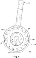
- the fuel-air mixture is spiraling in a counter-clockwise direction, shown by arrow CCW, out of the plane of the page in the orientation of Fig.
- the gliding plasma arc 138 When the gliding plasma arc 138 is subjected to the helical flow direction of the fuel-air mixture, the gliding plasma arc 138 is "blown" rapidly in the same direction as the flow of the fuel-air mixture. In other words, one end of the gliding plasma arc 138 remains relatively stationary at the electrode free end 142 while the opposite (laterally spaced) end of the gliding plasma arc 138 rotates rapidly around the circumference of the fuel nozzle 118. This spinning or twirling effect of the gliding plasma arc 138 creates a plasma field 302 that is in electrical communication with the fuel nozzle 118 and effectively encompasses a full 360 degrees around the electrode free end 142 of the plasma generator 120.
- the gliding plasma arc 138 is spun rapidly enough-through action of the helical flow direction of the fuel-air mixture-to appear to be a continuous disc-shaped plasma field 302.
- Creating this effectively "continuous" plasma field 302 from the rapidly rotating gliding plasma arc 138 assists with causing a supermajority-up to substantially all-of the fuel-air mixture to encounter plasma energy as the fuel-air mixture passes through the apparatus 100.
- the apparatus 100 can achieve a desired, and relatively high, level of fuel burning efficiency and/or flame stabilization.
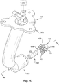
- Fig. 5 depicts an exploded perspective view of the apparatus 100.
- the swirler assembly 102 has been separated from the rest of the apparatus.
- two rings of swirler vanes 136 are Included in the swirler body 107.
- one ring of the swirler vanes 136 extends laterally inwardly from the swirler assembly Inner wall 108 and the other ring of swirler vanes 136 extends laterally outwardly from the swirler assembly Inner wall 108.
- This configuration shown in Fig. 5 further includes a mounting bracket 304 for the apparatus 100, to connect the apparatus 100 to other components of a jet engine.
- the mounting bracket 304 may be configured to fit any desired one or more engine designs.
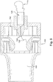
- Fig. 8 depicts a configuration of the apparatus 100 wherein the fuel mixing chamber 110 is elongated.
- the elongated fuel mixing chamber 110 may provide for a more homogenous fuel-air mixture to form.
- the plasma generator 120 depicted is also in fluid communication with the fuel nozzle fuel reservoir 116.
- the plasma generator 120 serves as a method of fuel deliver into the fuel nozzle mixing chamber 110.
- the electrode free end 142 may then serve multiple purposes, such as to direct fuel into the fuel nozzle mixing chamber 110 as well as create a plasma generator discharge 138.
- Fig. 9 depicts an embodiment of the apparatus 100 wherein the plasma generator 120 is in fluid communication with the fuel nozzle mixing chamber 110.
- the plasma generator may serve two purposes: to generate a plasma generator discharge 138, and to deliver fuel to the fuel nozzle mixing chamber 110.
- the plasma generator 120 depicted in this embodiment further includes a pointed electrode free end 142 geometry.
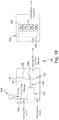
- Fig. 10 is a schematic depiction of the apparatus 100.
- the apparatus includes a swirler assembly 102, a fuel nozzle fuel reservoir 116, a plasma generator 120 that includes an electrode 140 and an electrode free end 142, a fuel nozzle 118, a fuel nozzle mixing chamber 110, a plasma generator discharge 138, a combustion chamber 122, a combustion chamber internal volume 128, a main flame 132, a pilot flame 134, and an R/R zone 130.
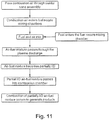
- Fig. 10 will be referenced during the below description of the operation of the apparatus 100 using the flowchart of Fig. 11 .
- First combustion air enters the swirler assembly Inlet 104, flows through the swirler body 107, and exits the swirler body 107 through the swirler assembly outlet 106.
- the combustion air achieves a helical flow direction.
- the combustion air proceeds into the fuel nozzle mixing chamber 110.
- Fuel also enters into the fuel nozzle mixing chamber 110 from the fluidly connected fuel reservoir 116.
- the plasma generator 120 creates a plasma generator discharge 138 that is in electrical communication with both some surface of the fuel nozzle 118 (or any other desired surface of the apparatus 100) and the electrode free end 142.
- the fuel-air mixture created in the fuel nozzle mixing chamber 110 passes through the plasma generator discharge 138 to create an at least partially I/D air-fuel mixture.
- the at least partially I/D air-fuel mixture comprising combustion air, then enters the combustion chamber internal volume 128 via the combustion chamber inlet 124.
- the combustion of the at least partially I/D fuel-air mixture with the combustion air occurs at least partially within the combustion chamber internal volume 128 to responsively produce products.
- the products then exit the combustion chamber internal volume 128 through the combustion chamber outlet 126.
- the plasma generator 120 may at least partially control the rate of at least one of (1) at least partial air-fuel ionization and/or dissociation and (2) fuel combustion within the combustion chamber 122. This is accomplished by user control (automatically and/or manually, in response to any desired inputs) of the energy provided to the plasma generator 120.
- the plasma generator 120 can at least partially ionize and/or dissociate the fuel-air mixture responsive to control commands, from any desired source (e.g., a Full Authority Digital Engine Control ["FADEC"], not shown), for combustion by at least one of the main flame 132 and the pilot flame 134.
- This control system may gather information about mass flow rate, combustion or other relative parameters by sensing the electrical properties of the discharge.
- an ignition source (shown schematically at 306 in Fig. 2 as a pilot burner and operatively connected to the plasma generator 120) may be located at least partially within a selected one of the fuel nozzle mixing chamber 110 and the combustion chamber 122.
- the ignition source 306. when present, may alter the rate of at least partial fuel-air ionization and/or dissociation responsive to variant operating conditions.
- there may be one or more sensors (not shown), of any suitable type, such as, but not limited to, pressure, temperature, electrical field, or any combination thereof, provided at any desired location(s) in/near the apparatus 100. to provide the ignition source 306. directly or via a control device, with information on the variant operating conditions such that the plasma is modulated to ensure desired combustion stability.
- Another way of thinking about at least a portion of the operation of the apparatus 100 is to consider that an aerodynamic swirl is used to impart a rotation to the at least partially I/D fuel-air mixture.
- This rotation is oriented substantially about a rotational axis substantially parallel to a longitudinal axis of the plasma generator 120. The rotation contributes to a quasi-spatially uniform discharge of the at least partially I/D fuel-air mixture from the plasma generator 120.
- the apparatus 100 includes, or is otherwise associated with, a mixer 204. a radial swirl vane 206 of the mixer 204, a main fuel delivery orifice 208. a main fuel annulus 210. a ceramic insulator 212, a pilot fuel in 214, an inner swirler vane 216, an annular flow separator 218, an outer swirler vane 220. a main fuel delivery line 222. a pilot fuel delivery orifice 224, a prefilming surface for pilot fuel 226. and a venturi throat of the fuel nozzle 228.
- Any component could be provided with a user-perceptible marking to indicate a material, configuration, at least one dimension, or the like pertaining to that component, the user-perceptible marking aiding a user in selecting one component from an array of similar components for a particular use environment.
- certain components described herein are shown as having specific geometric shapes, all structures of this disclosure may have any suitable shapes, sizes, configurations, relative relationships, cross-sectional areas, or any other physical characteristics as desirable for a particular application.
- Any structures or features described with reference to one aspect or configuration could be provided, singly or in combination with other structures or features, to any other aspect or configuration, as it would be impractical to describe each of the aspects and configurations discussed herein as having all of the options discussed with respect to all of the other aspects and configurations.
Claims (14)
- Vorrichtung (100) zum Unterstützen der Verbrennung von Brennstoff, wobei die Vorrichtung (100) Folgendes umfasst:eine Verwirbleranordnung (102), die mindestens einen Verwirbleranordnungseinlass (104) und mindestens einen Verwirbleranordnungsauslass (106) aufweist, der in Längsrichtung von dem mindestens einen Verwirbleranordnungseinlass (104) durch einen Verwirblerkörper (107) getrennt ist, der eine Verwirbleranordnungsinnenwand (108) definiert, wobei der Verwirblerkörper (107) zwei Ringe von Verwirblerschaufeln (136) einschließt, wobei sich ein Ring der Verwirblerschaufeln (136) seitlich nach innen von der Verwirbleranordnungsinnenwand (108) erstreckt und der andere Ring der Verwirblerschaufeln (136) sich seitlich nach außen von der Verwirbleranordnungsinnenwand (108) erstreckt;eine Brennstoffdüse (118), die eine Brennstoffdüsenmischkammer (110), einen Brennstoffdüsenlufteinlass (112) und einen Brennstoffdüsenluftauslass (114) aufweist, wobei die Brennstoffdüsenmischkammer (110) sowohl mit einem Brennstoffdüsenbrennstoffreservoir (116) als auch mit dem Brennstoffdüsenlufteinlass (112) in Fluidverbindung steht, der Brennstoffdüsenlufteinlass (112) ermöglicht, dass Luft aus dem Verwirbleranordnungsauslass (106) in die Brennstoffdüse (118) strömt, wobei Brennstoff aus dem Brennstoffdüsenbrennstoffreservoir (116) in die Brennstoffdüsenmischkammer (110) geleitet wird und sich der Brennstoff innerhalb der Brennstoffdüsenmischkammer (110) zumindest teilweise mit der darin befindlichen Luft zu einem Brennstoff-Luft-Gemisch verbindet;mindestens einen Plasmagenerator (120), der sich zumindest teilweise innerhalb der Brennstoffdüse (118) befindet, wobei der Plasmagenerator (120) das Brennstoff-Luft-Gemisch zumindest teilweise ionisiert und/oder dissoziiert, um ein zumindest teilweise ionisiertes Luft-Brennstoff-Gemisch und/oder ein zumindest teilweise dissoziiertes Luft-Brennstoff-Gemisch ("zumindest teilweise 1/D-Luft-Brennstoff-Gemisch") über eine Entladung des Plasmagenerators (138) zu erzeugen;eine Brennkammer (122), die einen Brennkammereinlass (124) aufweist, der in Fluidverbindung mit dem Verwirbleranordnungsauslass (106) steht, wobei die Brennkammer (122) einen Brennkammerauslass (126) aufweist, wobei der Brennkammereinlass und -auslass (124, 126) in Längsrichtung durch ein Brennkammerinnenvolumen (128) getrennt sind, das eine R/R-Zone (130), eine Hauptflamme (132) und eine Zündflamme (134) einschließt, wobei der Brennkammereinlass (124) das durch den Plasmagenerator (120) erzeugte, zumindest teilweise 1/D-Luft-Brennstoff-Gemisch in das Brennkammerinnenvolumen (128) einlässt;wobei die Verwirbleranordnung (102) und der mindestens eine Plasmagenerator (120) so angeordnet sind, dass Verbrennungsluft in den Verwirbleranordnungseinlass (104) eintritt, durch den Verwirblerkörper (107) strömt und den Verwirblerkörper (107) durch den Verwirbleranordnungsauslass mit einer aerodynamischen Verwirbelung verlässt, die eine Rotationsachse aufweist, die im Wesentlichen parallel zu einer Längsachse des Plasmagenerators (120) verläuft, wobei die Verbrennungsluft vom Verwirbleranordnungsauslass (106) durch den Brennkammereinlass (124) in das Brennkammerinnenvolumen (128) strömt;wobei die aerodynamische Verwirbelung dem zumindest teilweise 1/D-Brennstoff-Luft-Gemisch eine Rotation verleiht, die zu einer quasi-räumlich gleichmäßigen Entladung des zumindest teilweise 1/D-Brennstoff-Luft-Gemischs aus dem Plasmagenerator (120) beiträgt; undwobei die Verbrennung des zumindest teilweise 1/D-Luft-Brennstoff-Gemischs mit der Verbrennungsluft zumindest teilweise innerhalb des Brennkammerinnenvolumens (128) auftritt, um als Reaktion darauf Produkte herzustellen, wobei die Produkte das Brennkammerinnenvolumen (128) durch den Brennkammerauslass (126) verlassen.
- Vorrichtung nach Anspruch 1, wobei der Plasmagenerator zumindest teilweise die Rate der teilweisen Luft-Brennstoff-Ionisierung und/oder Dissoziation und der Brennstoffverbrennung innerhalb der Brennkammer steuert.
- Vorrichtung (100) nach Anspruch 1, wobei der Plasmagenerator (120) einen Plasmagenerator (120) mit gleitendem Lichtbogen einschließt, der einen gleitenden Plasmabogen (302) erzeugt, der sowohl mit dem Plasmagenerator (120) als auch mit einer Oberfläche der Brennstoffdüse (118) in elektrischer Verbindung steht.
- Vorrichtung (100) nach Anspruch 2, einschließlich eines Brennstoffdüsenmischergehäuses (202), das in Fluidverbindung mit dem Brennstoffdüsenbrennstoffreservoir (116) steht und die Brennstoffdüse (118) zumindest teilweise seitlich umgibt, wobei der Plasmagenerator (120) einen gleitenden Plasmalichtbogen erzeugt, der sowohl mit dem Plasmagenerator (120) als auch mit einer Oberfläche des Brennstoffdüsenmischergehäuses (202) in elektrischer Verbindung steht.
- Vorrichtung (100) nach Anspruch 1, wobei der Plasmagenerator (120) eine Elektrode (140) mit einem freien Elektrodenende (142) aufweist, wobei sich die Entladung des Plasmagenerators (138) von dem freien Elektrodenende (142) in die Brennkammer (122) seitlich und/oder in Längsrichtung nach außen erstreckt.
- Vorrichtung (100) nach einem der vorangehenden Ansprüche, wobei der Plasmagenerator (120) ein gepulster Nanosekundenplasmagenerator, ein dielektrischer Barriereentladungsplasmagenerator, ein Hochfrequenzentladungsplasmagenerator, ein Laserplasmagenerator und/oder ein Mikrowellenplasmagenerator ist.
- Vorrichtung (100) nach einem der vorangehenden Ansprüche, wobei die Entladung des Plasmagenerators (138) eine gleitende Bogenentladung, eine Streamerentladung, eine dielektrische Barrierenentladung, eine HF-Entladung und/oder eine gepulste Nanosekundenentladung ist.
- Vorrichtung (100) nach Anspruch 1, wobei der Plasmagenerator (120) eine Elektrode (140) mit einem freien Elektrodenende (142) aufweist, wobei sich die Elektrode (140) von einem verbleibenden Abschnitt des Plasmagenerators (120) in Längsrichtung erstreckt, um das freie Elektrodenende (142) im Wesentlichen innerhalb der durch den Brennstoffdüsenluftauslass (114) definierten seitlichen Ebene zu platzieren.
- Vorrichtung (100) nach Anspruch 1, wobei der Plasmagenerator (120) eine Elektrode (140) mit einem freien Elektrodenende (142) aufweist, wobei sich die Elektrode (140) von einem verbleibenden Abschnitt des Plasmagenerators (120) aus erstreckt, um eine durch den Brennstoffdüsenluftauslass (114) gebildete seitliche Ebene in Längsrichtung zwischen der Brennstoffdüsenmischkammer (110) und dem freien Elektrodenende (142) einzufügen.
- Vorrichtung (100) nach einem der Ansprüche 7 und 8, wobei die Entladung des Plasmagenerators (138) ein Plasmafeld ist, das in elektrischer Verbindung mit dem freien Elektrodenende (142) und einer Oberfläche der Brennstoffdüse (118) steht.
- Vorrichtung (100) nach Anspruch 1, wobei der Plasmagenerator (120) eine Elektrode (140) mit einem freien Elektrodenende (142) aufweist, wobei sich die Elektrode (140) vollständig innerhalb der Brennstoffdüsenmischkammer (110) befindet und wobei die Entladung des Plasmagenerators (138) ein Plasmafeld ist, das in elektrischer Verbindung mit dem freien Elektrodenende (142) und der Brennstoffdüse (118) steht.
- Vorrichtung nach Anspruch 1, wobei der Brennkammereinlass (124) so angeordnet ist, dass das durch den Plasmagenerator (120) erzeugte, zumindest teilweise I/D-Luft-Brennstoff-Gemisch in die Brrennkammer (122) eintritt, indem es zunächst die R/R-Zone (130) durchläuft.
- Verfahren zum Unterstützen der Verbrennung von Brennstoff, das Folgendes umfasst:Bereitstellen einer Vorrichtung (100), die Folgendes einschließt:eine Verwirbleranordnung (102), die mindestens einen Verwirbleranordnungseinlass (104) und mindestens einen Verwirbleranordnungsauslass (106) aufweist, der in Längsrichtung von dem mindestens einen Verwirbleranordnungseinlass (104) durch einen Verwirblerkörper (107) getrennt ist, der eine Verwirbleranordnungsinnenwand (108) definiert, wobei der Verwirblerkörper (107) zwei Ringe von Verwirblerschaufeln (136) einschließt, wobei sich ein Ring der Verwirblerschaufeln (136) seitlich nach innen von der Verwirbleranordnungsinnenwand (108) erstreckt und der andere Ring der Verwirblerschaufeln (136) sich seitlich nach außen von der Verwirbleranordnungsinnenwand (108) erstreckt,eine Brennstoffdüse (118), die eine Brennstoffdüsenmischkammer (110), einen Brennstoffdüsenlufteinlass (112) und einen Brennstoffdüsenluftauslass (114) aufweist, wobei die Brennstoffdüsenmischkammer (110) sowohl mit einem Brennstoffdüsenbrennstoffreservoir (116) als auch mit dem Brennstoffdüsenlufteinlass (112) in Fluidverbindung steht, wobei der Brennstoffdüsenlufteinlass (112) es ermöglicht, dass Luft aus dem Verwirbleranordnungsauslass (106) in die Brennstoffdüse (118) strömt,mindestens einen Plasmagenerator (120), der sich zumindest teilweise innerhalb der Brennstoffdüse (118) befindet, undeine Brennkammer (122), die einen Brennkammereinlass (124) aufweist, der in Fluidverbindung mit dem Verwirbleranordnungsauslass (106) steht, wobei die Brennkammer (122) einen Brennkammerauslass (126) aufweist, wobei der Brennkammereinlass und -auslass (124, 126) in Längsrichtung durch ein Brennkammerinnenvolumen (128) getrennt sind, wobei das Brennkammerinnenvolumen (128) eine R/R-Zone (130), eine Hauptflamme (132) und eine Zündflamme (134) einschließt;Bereitstellen von Brennstoff für die Brennstoffdüsenmischkammer (110) aus dem Brennstoffdüsenbrennstoffreservoir (116);Erzeugen eines Brennstoff-Luft-Gemisches durch Kombinieren von Brennstoff und Luft innerhalb der Brennstoffdüsenmischkammer (110);Erzeugen eines Plasmafeldes mit einem Plasmagenerator (120), der sich zumindest teilweise innerhalb der Brennstoffdüse (118) befindet;Erzeugen, mit dem Plasmagenerator (120), ein zumindest teilweise ionisiertes Luft-Brennstoff-Gemisch und/oder ein zumindest teilweise dissoziiertes Luft-Brennstoff-Gemisch ("zumindest teilweise I/D-Luft-Brennstoff-Gemisch") aus mindestens einem Abschnitt des Brennstoff-Luft-Gemisches;Bereitstellen einer aerodynamischen Verwirbelung, um dem zumindest teilweise I/D-Brennstoff-Luft-Gemisch eine Rotation zu verleihen, wobei die Rotation im Wesentlichen um eine Rotationsachse ausgerichtet ist, die im Wesentlichen parallel zu einer Längsachse des Plasmagenerators (120) verläuft, wobei die Rotation zu einer quasi-räumlich gleichmäßigen Entladung des zumindest teilweise I/D-Brennstoff-Luft-Gemisches aus dem Plasmagenerator (120) beiträgt;Verbrennen mindestens eines Abschnitts des Brennstoff-Luft-Gemischs in der Brennkammer (122) mit dem Plasmafeld, das von dem zumindest teilweise I/D-Luft-Brennstoff-Gemisch erzeugt wird, um Produkte herzustellen; undLeiten von Verbrennungsluft durch den Verwirbleranordnungseinlass (104), durch den Verwirblerkörper (107), und die Verbrennungsluft, die den Verwirblerkörper (107) verlässt, durch den Verwirbleranordnungsauslass (106), um der Strömungsrichtung der Verbrennungsluft einen spiralförmigen Aspekt zu verleihen.
- Verfahren nach Anspruch 13, das Folgendes einschließt:Bereitstellen von Steuerbefehlen; undIonisieren und/oder Dissoziieren des Brennstoff-Luft-Gemisches als Reaktion auf die Steuerbefehle zum Verbrennen durch die Hauptflamme (132) und/oder die Zündflamme (134).
Applications Claiming Priority (2)
| Application Number | Priority Date | Filing Date | Title |
|---|---|---|---|
| US201461990314P | 2014-05-08 | 2014-05-08 | |
| PCT/US2015/029864 WO2015172007A1 (en) | 2014-05-08 | 2015-05-08 | Method and apparatus for assisting with the combustion of fuel |
Publications (2)
| Publication Number | Publication Date |
|---|---|
| EP3140595A1 EP3140595A1 (de) | 2017-03-15 |
| EP3140595B1 true EP3140595B1 (de) | 2021-07-14 |
Family
ID=53189230
Family Applications (1)
| Application Number | Title | Priority Date | Filing Date |
|---|---|---|---|
| EP15723415.4A Active EP3140595B1 (de) | 2014-05-08 | 2015-05-08 | Verfahren und vorrichtung zur unterstützung der verbrennung von brennstoff |
Country Status (3)
| Country | Link |
|---|---|
| US (2) | US9423133B2 (de) |
| EP (1) | EP3140595B1 (de) |
| WO (1) | WO2015172007A1 (de) |
Families Citing this family (20)
| Publication number | Priority date | Publication date | Assignee | Title |
|---|---|---|---|---|
| US9423133B2 (en) * | 2014-05-08 | 2016-08-23 | FGC Plasms Solutions LLC | Method and apparatus for assisting with the combustion of fuel |
| EP3062019B1 (de) * | 2015-02-27 | 2018-11-21 | Ansaldo Energia Switzerland AG | Verfahren und vorrichtung zur flammenstabilisation in einem brennersystem einer stationären brennkraftmaschine |
| FR3039254B1 (fr) * | 2015-07-24 | 2021-10-08 | Snecma | Chambre de combustion comportant des dispositifs d'injection additionnels debouchant directement dans les zones de recirculation de coin, turbomachine la comprenant, et procede d'alimentation en carburant de celle-ci |
| FR3047277B1 (fr) * | 2016-01-29 | 2019-12-20 | Arianegroup Sas | Element d'injection muni d'un dispositif d'allumage |
| CN105783031B (zh) * | 2016-04-18 | 2018-07-10 | 中国科学院工程热物理研究所 | 一种集成等离子激励器、喷嘴阵列和燃烧器 |
| US10502425B2 (en) * | 2016-06-03 | 2019-12-10 | General Electric Company | Contoured shroud swirling pre-mix fuel injector assembly |
| WO2018075854A1 (en) * | 2016-10-21 | 2018-04-26 | Fgc Plasma Solutions | Apparatus and method for using plasma to assist with the combustion of fuel |
| US10446373B2 (en) * | 2017-03-17 | 2019-10-15 | Cu Aerospace, Llc | Cyclotronic plasma actuator with arc-magnet for active flow control |
| WO2018170383A1 (en) * | 2017-03-17 | 2018-09-20 | Cu Aerospace, Llc | Cyclotronic plasma actuator with arc-magnet for active flow control |
| KR101889542B1 (ko) * | 2017-04-18 | 2018-08-17 | 두산중공업 주식회사 | 연소기 노즐 조립체 및 이를 포함하는 가스터빈 |
| CN110886657A (zh) * | 2019-10-30 | 2020-03-17 | 北京动力机械研究所 | 一种吸气式发动机等离子体点火系统 |
| CN111734532B (zh) * | 2020-06-21 | 2023-02-14 | 中国人民解放军空军工程大学 | 一种基于旋流孔的丝状电弧等离子体激励器 |
| US11754288B2 (en) * | 2020-12-09 | 2023-09-12 | General Electric Company | Combustor mixing assembly |
| CN113027615B (zh) * | 2021-04-14 | 2022-11-04 | 中国航空发动机研究院 | 一种利用轴向电极控制燃烧的发动机 |
| CN113091090B (zh) * | 2021-04-14 | 2022-11-22 | 中国航空发动机研究院 | 一种利用电场控制燃烧区燃烧的航空发动机 |
| CN113091089A (zh) * | 2021-04-14 | 2021-07-09 | 中国航空发动机研究院 | 一种利用电场控制掺混区燃烧的航空发动机 |
| CN113446129B (zh) * | 2021-07-26 | 2022-09-30 | 中国人民解放军战略支援部队航天工程大学 | 一种中小推力火箭发动机高效稳定燃烧喷注器 |
| US11795879B2 (en) * | 2021-12-20 | 2023-10-24 | General Electric Company | Combustor with an igniter provided within at least one of a fuel injector or a compressed air passage |
| CN114992673A (zh) * | 2022-06-10 | 2022-09-02 | 中国科学院工程热物理研究所 | 可抑制燃烧室振荡燃烧的喷嘴 |
| CN115218221B (zh) * | 2022-06-19 | 2023-08-11 | 中国人民解放军空军工程大学 | 一种旋转滑动弧等离子体调控燃烧装置 |
Citations (4)
| Publication number | Priority date | Publication date | Assignee | Title |
|---|---|---|---|---|
| US20020092302A1 (en) * | 2001-01-18 | 2002-07-18 | Johnson Arthur Wesley | Combustor mixer having plasma generating nozzle |
| US20050044854A1 (en) * | 2003-09-02 | 2005-03-03 | Snecma-Moteurs | Air/fuel injection system having cold plasma generating means |
| US20090165436A1 (en) * | 2007-12-28 | 2009-07-02 | General Electric Company | Premixed, preswirled plasma-assisted pilot |
| US20110126548A1 (en) * | 2007-05-31 | 2011-06-02 | Thomas Hammer | Method and device for the combustion of hydrocarbon-containing fuels |
Family Cites Families (5)
| Publication number | Priority date | Publication date | Assignee | Title |
|---|---|---|---|---|
| FR2269646B1 (de) * | 1974-04-30 | 1976-12-17 | Snecma | |
| US20080033066A1 (en) * | 2006-08-04 | 2008-02-07 | General Electric Company | System and method for enhancing co production in a gas to liquid system |
| FR2919672B1 (fr) * | 2007-07-30 | 2014-02-14 | Snecma | Injecteur de carburant dans une chambre de combustion de turbomachine |
| WO2015130655A1 (en) * | 2014-02-26 | 2015-09-03 | GM Global Technology Operations LLC | Plasma ignition device |
| US9423133B2 (en) * | 2014-05-08 | 2016-08-23 | FGC Plasms Solutions LLC | Method and apparatus for assisting with the combustion of fuel |
-
2015
- 2015-05-08 US US14/707,427 patent/US9423133B2/en active Active
- 2015-05-08 EP EP15723415.4A patent/EP3140595B1/de active Active
- 2015-05-08 WO PCT/US2015/029864 patent/WO2015172007A1/en active Application Filing
-
2016
- 2016-08-18 US US15/239,993 patent/US10648672B2/en active Active
Patent Citations (4)
| Publication number | Priority date | Publication date | Assignee | Title |
|---|---|---|---|---|
| US20020092302A1 (en) * | 2001-01-18 | 2002-07-18 | Johnson Arthur Wesley | Combustor mixer having plasma generating nozzle |
| US20050044854A1 (en) * | 2003-09-02 | 2005-03-03 | Snecma-Moteurs | Air/fuel injection system having cold plasma generating means |
| US20110126548A1 (en) * | 2007-05-31 | 2011-06-02 | Thomas Hammer | Method and device for the combustion of hydrocarbon-containing fuels |
| US20090165436A1 (en) * | 2007-12-28 | 2009-07-02 | General Electric Company | Premixed, preswirled plasma-assisted pilot |
Also Published As
| Publication number | Publication date |
|---|---|
| US20150323187A1 (en) | 2015-11-12 |
| US9423133B2 (en) | 2016-08-23 |
| WO2015172007A1 (en) | 2015-11-12 |
| US20160356501A1 (en) | 2016-12-08 |
| EP3140595A1 (de) | 2017-03-15 |
| US10648672B2 (en) | 2020-05-12 |
Similar Documents
| Publication | Publication Date | Title |
|---|---|---|
| US10648672B2 (en) | Method and apparatus for assisting with the combustion of fuel by using a plasma generator within a fuel nozzle | |
| EP3529535B1 (de) | Vorrichtung zur verwendung von plasma zur unterstützung der verbrennung von brennstoff | |
| US7810333B2 (en) | Method and apparatus for operating a turbine engine | |
| JP5188307B2 (ja) | ターボ機械燃焼室に燃料を噴射するための燃料噴射装置 | |
| JP4229614B2 (ja) | プラズマ生成ノズルを備える燃焼器ミキサ | |
| US20090165436A1 (en) | Premixed, preswirled plasma-assisted pilot | |
| KR101749875B1 (ko) | 가스터빈 연소기 및 이를 구비한 가스터빈기관 | |
| EP2075508B1 (de) | Brennkammer einer gasturbine | |
| KR20080092858A (ko) | 전기역학적 선회기와 이를 사용하는 연소 장치 및 방법 | |
| ES2830039T3 (es) | Aparato de combustión con elemento de premezcla | |
| US10570820B2 (en) | Nozzle, combustion apparatus, and gas turbine | |
| KR102281567B1 (ko) | 역화현상을 방지할 수 있는 수소가스 연소장치 | |
| JP2005077087A (ja) | 低温プラズマ発生手段を有する空気/燃料噴射システム | |
| JP2010085087A (ja) | ガスタービン機関のための燃料ランス | |
| JP2010085087A5 (de) | ||
| JP2013140004A (ja) | 燃焼器燃料ノズル及び燃焼器への燃料供給方法 | |
| US20160201918A1 (en) | Small arrayed swirler system for reduced emissions and noise | |
| EP2434218A1 (de) | Brenner mit geringen NOx-Emissionen | |
| US20230341126A1 (en) | Plasma injection modules | |
| EP1945930B1 (de) | Turbomotormischkanal und verfahren zum starten des motors | |
| US11725824B2 (en) | Turbulence generator mixer for rotating detonation engine | |
| JP2013242101A (ja) | バーナ及びガスタービン燃焼器 | |
| CN116006968A (zh) | 基于流动控制的沿面介质阻挡放电防止回火装置与方法 |
Legal Events
| Date | Code | Title | Description |
|---|---|---|---|
| STAA | Information on the status of an ep patent application or granted ep patent |
Free format text: STATUS: THE INTERNATIONAL PUBLICATION HAS BEEN MADE |
|
| PUAI | Public reference made under article 153(3) epc to a published international application that has entered the european phase |
Free format text: ORIGINAL CODE: 0009012 |
|
| STAA | Information on the status of an ep patent application or granted ep patent |
Free format text: STATUS: REQUEST FOR EXAMINATION WAS MADE |
|
| 17P | Request for examination filed |
Effective date: 20161024 |
|
| AK | Designated contracting states |
Kind code of ref document: A1 Designated state(s): AL AT BE BG CH CY CZ DE DK EE ES FI FR GB GR HR HU IE IS IT LI LT LU LV MC MK MT NL NO PL PT RO RS SE SI SK SM TR |
|
| AX | Request for extension of the european patent |
Extension state: BA ME |
|
| DAV | Request for validation of the european patent (deleted) | ||
| DAX | Request for extension of the european patent (deleted) | ||
| STAA | Information on the status of an ep patent application or granted ep patent |
Free format text: STATUS: EXAMINATION IS IN PROGRESS |
|
| 17Q | First examination report despatched |
Effective date: 20190524 |
|
| STAA | Information on the status of an ep patent application or granted ep patent |
Free format text: STATUS: EXAMINATION IS IN PROGRESS |
|
| GRAP | Despatch of communication of intention to grant a patent |
Free format text: ORIGINAL CODE: EPIDOSNIGR1 |
|
| STAA | Information on the status of an ep patent application or granted ep patent |
Free format text: STATUS: GRANT OF PATENT IS INTENDED |
|
| INTG | Intention to grant announced |
Effective date: 20201023 |
|
| GRAJ | Information related to disapproval of communication of intention to grant by the applicant or resumption of examination proceedings by the epo deleted |
Free format text: ORIGINAL CODE: EPIDOSDIGR1 |
|
| STAA | Information on the status of an ep patent application or granted ep patent |
Free format text: STATUS: EXAMINATION IS IN PROGRESS |
|
| GRAP | Despatch of communication of intention to grant a patent |
Free format text: ORIGINAL CODE: EPIDOSNIGR1 |
|
| STAA | Information on the status of an ep patent application or granted ep patent |
Free format text: STATUS: GRANT OF PATENT IS INTENDED |
|
| INTC | Intention to grant announced (deleted) | ||
| INTG | Intention to grant announced |
Effective date: 20210211 |
|
| GRAJ | Information related to disapproval of communication of intention to grant by the applicant or resumption of examination proceedings by the epo deleted |
Free format text: ORIGINAL CODE: EPIDOSDIGR1 |
|
| STAA | Information on the status of an ep patent application or granted ep patent |
Free format text: STATUS: EXAMINATION IS IN PROGRESS |
|
| GRAP | Despatch of communication of intention to grant a patent |
Free format text: ORIGINAL CODE: EPIDOSNIGR1 |
|
| STAA | Information on the status of an ep patent application or granted ep patent |
Free format text: STATUS: GRANT OF PATENT IS INTENDED |
|
| GRAS | Grant fee paid |
Free format text: ORIGINAL CODE: EPIDOSNIGR3 |
|
| GRAA | (expected) grant |
Free format text: ORIGINAL CODE: 0009210 |
|
| STAA | Information on the status of an ep patent application or granted ep patent |
Free format text: STATUS: THE PATENT HAS BEEN GRANTED |
|
| INTC | Intention to grant announced (deleted) | ||
| INTG | Intention to grant announced |
Effective date: 20210525 |
|
| AK | Designated contracting states |
Kind code of ref document: B1 Designated state(s): AL AT BE BG CH CY CZ DE DK EE ES FI FR GB GR HR HU IE IS IT LI LT LU LV MC MK MT NL NO PL PT RO RS SE SI SK SM TR |
|
| REG | Reference to a national code |
Ref country code: GB Ref legal event code: FG4D |
|
| REG | Reference to a national code |
Ref country code: IE Ref legal event code: FG4D |
|
| REG | Reference to a national code |
Ref country code: DE Ref legal event code: R096 Ref document number: 602015071285 Country of ref document: DE |
|
| REG | Reference to a national code |
Ref country code: AT Ref legal event code: REF Ref document number: 1410942 Country of ref document: AT Kind code of ref document: T Effective date: 20210815 |
|
| REG | Reference to a national code |
Ref country code: LT Ref legal event code: MG9D |
|
| REG | Reference to a national code |
Ref country code: NL Ref legal event code: MP Effective date: 20210714 |
|
| REG | Reference to a national code |
Ref country code: AT Ref legal event code: MK05 Ref document number: 1410942 Country of ref document: AT Kind code of ref document: T Effective date: 20210714 |
|
| PG25 | Lapsed in a contracting state [announced via postgrant information from national office to epo] |
Ref country code: NO Free format text: LAPSE BECAUSE OF FAILURE TO SUBMIT A TRANSLATION OF THE DESCRIPTION OR TO PAY THE FEE WITHIN THE PRESCRIBED TIME-LIMIT Effective date: 20211014 Ref country code: NL Free format text: LAPSE BECAUSE OF FAILURE TO SUBMIT A TRANSLATION OF THE DESCRIPTION OR TO PAY THE FEE WITHIN THE PRESCRIBED TIME-LIMIT Effective date: 20210714 Ref country code: PT Free format text: LAPSE BECAUSE OF FAILURE TO SUBMIT A TRANSLATION OF THE DESCRIPTION OR TO PAY THE FEE WITHIN THE PRESCRIBED TIME-LIMIT Effective date: 20211115 Ref country code: ES Free format text: LAPSE BECAUSE OF FAILURE TO SUBMIT A TRANSLATION OF THE DESCRIPTION OR TO PAY THE FEE WITHIN THE PRESCRIBED TIME-LIMIT Effective date: 20210714 Ref country code: FI Free format text: LAPSE BECAUSE OF FAILURE TO SUBMIT A TRANSLATION OF THE DESCRIPTION OR TO PAY THE FEE WITHIN THE PRESCRIBED TIME-LIMIT Effective date: 20210714 Ref country code: AT Free format text: LAPSE BECAUSE OF FAILURE TO SUBMIT A TRANSLATION OF THE DESCRIPTION OR TO PAY THE FEE WITHIN THE PRESCRIBED TIME-LIMIT Effective date: 20210714 Ref country code: BG Free format text: LAPSE BECAUSE OF FAILURE TO SUBMIT A TRANSLATION OF THE DESCRIPTION OR TO PAY THE FEE WITHIN THE PRESCRIBED TIME-LIMIT Effective date: 20211014 Ref country code: LT Free format text: LAPSE BECAUSE OF FAILURE TO SUBMIT A TRANSLATION OF THE DESCRIPTION OR TO PAY THE FEE WITHIN THE PRESCRIBED TIME-LIMIT Effective date: 20210714 Ref country code: HR Free format text: LAPSE BECAUSE OF FAILURE TO SUBMIT A TRANSLATION OF THE DESCRIPTION OR TO PAY THE FEE WITHIN THE PRESCRIBED TIME-LIMIT Effective date: 20210714 Ref country code: RS Free format text: LAPSE BECAUSE OF FAILURE TO SUBMIT A TRANSLATION OF THE DESCRIPTION OR TO PAY THE FEE WITHIN THE PRESCRIBED TIME-LIMIT Effective date: 20210714 Ref country code: SE Free format text: LAPSE BECAUSE OF FAILURE TO SUBMIT A TRANSLATION OF THE DESCRIPTION OR TO PAY THE FEE WITHIN THE PRESCRIBED TIME-LIMIT Effective date: 20210714 |
|
| PG25 | Lapsed in a contracting state [announced via postgrant information from national office to epo] |
Ref country code: PL Free format text: LAPSE BECAUSE OF FAILURE TO SUBMIT A TRANSLATION OF THE DESCRIPTION OR TO PAY THE FEE WITHIN THE PRESCRIBED TIME-LIMIT Effective date: 20210714 Ref country code: LV Free format text: LAPSE BECAUSE OF FAILURE TO SUBMIT A TRANSLATION OF THE DESCRIPTION OR TO PAY THE FEE WITHIN THE PRESCRIBED TIME-LIMIT Effective date: 20210714 Ref country code: GR Free format text: LAPSE BECAUSE OF FAILURE TO SUBMIT A TRANSLATION OF THE DESCRIPTION OR TO PAY THE FEE WITHIN THE PRESCRIBED TIME-LIMIT Effective date: 20211015 |
|
| REG | Reference to a national code |
Ref country code: DE Ref legal event code: R097 Ref document number: 602015071285 Country of ref document: DE |
|
| PG25 | Lapsed in a contracting state [announced via postgrant information from national office to epo] |
Ref country code: DK Free format text: LAPSE BECAUSE OF FAILURE TO SUBMIT A TRANSLATION OF THE DESCRIPTION OR TO PAY THE FEE WITHIN THE PRESCRIBED TIME-LIMIT Effective date: 20210714 |
|
| PLBE | No opposition filed within time limit |
Free format text: ORIGINAL CODE: 0009261 |
|
| STAA | Information on the status of an ep patent application or granted ep patent |
Free format text: STATUS: NO OPPOSITION FILED WITHIN TIME LIMIT |
|
| PG25 | Lapsed in a contracting state [announced via postgrant information from national office to epo] |
Ref country code: SM Free format text: LAPSE BECAUSE OF FAILURE TO SUBMIT A TRANSLATION OF THE DESCRIPTION OR TO PAY THE FEE WITHIN THE PRESCRIBED TIME-LIMIT Effective date: 20210714 Ref country code: SK Free format text: LAPSE BECAUSE OF FAILURE TO SUBMIT A TRANSLATION OF THE DESCRIPTION OR TO PAY THE FEE WITHIN THE PRESCRIBED TIME-LIMIT Effective date: 20210714 Ref country code: RO Free format text: LAPSE BECAUSE OF FAILURE TO SUBMIT A TRANSLATION OF THE DESCRIPTION OR TO PAY THE FEE WITHIN THE PRESCRIBED TIME-LIMIT Effective date: 20210714 Ref country code: EE Free format text: LAPSE BECAUSE OF FAILURE TO SUBMIT A TRANSLATION OF THE DESCRIPTION OR TO PAY THE FEE WITHIN THE PRESCRIBED TIME-LIMIT Effective date: 20210714 Ref country code: CZ Free format text: LAPSE BECAUSE OF FAILURE TO SUBMIT A TRANSLATION OF THE DESCRIPTION OR TO PAY THE FEE WITHIN THE PRESCRIBED TIME-LIMIT Effective date: 20210714 Ref country code: AL Free format text: LAPSE BECAUSE OF FAILURE TO SUBMIT A TRANSLATION OF THE DESCRIPTION OR TO PAY THE FEE WITHIN THE PRESCRIBED TIME-LIMIT Effective date: 20210714 |
|
| 26N | No opposition filed |
Effective date: 20220419 |
|
| PG25 | Lapsed in a contracting state [announced via postgrant information from national office to epo] |
Ref country code: IT Free format text: LAPSE BECAUSE OF FAILURE TO SUBMIT A TRANSLATION OF THE DESCRIPTION OR TO PAY THE FEE WITHIN THE PRESCRIBED TIME-LIMIT Effective date: 20210714 |
|
| REG | Reference to a national code |
Ref country code: CH Ref legal event code: PL |
|
| REG | Reference to a national code |
Ref country code: BE Ref legal event code: MM Effective date: 20220531 |
|
| PG25 | Lapsed in a contracting state [announced via postgrant information from national office to epo] |
Ref country code: MC Free format text: LAPSE BECAUSE OF FAILURE TO SUBMIT A TRANSLATION OF THE DESCRIPTION OR TO PAY THE FEE WITHIN THE PRESCRIBED TIME-LIMIT Effective date: 20210714 Ref country code: LU Free format text: LAPSE BECAUSE OF NON-PAYMENT OF DUE FEES Effective date: 20220508 Ref country code: LI Free format text: LAPSE BECAUSE OF NON-PAYMENT OF DUE FEES Effective date: 20220531 Ref country code: CH Free format text: LAPSE BECAUSE OF NON-PAYMENT OF DUE FEES Effective date: 20220531 |
|
| PG25 | Lapsed in a contracting state [announced via postgrant information from national office to epo] |
Ref country code: IE Free format text: LAPSE BECAUSE OF NON-PAYMENT OF DUE FEES Effective date: 20220508 |
|
| PG25 | Lapsed in a contracting state [announced via postgrant information from national office to epo] |
Ref country code: BE Free format text: LAPSE BECAUSE OF NON-PAYMENT OF DUE FEES Effective date: 20220531 |
|
| P01 | Opt-out of the competence of the unified patent court (upc) registered |
Effective date: 20230522 |
|
| PGFP | Annual fee paid to national office [announced via postgrant information from national office to epo] |
Ref country code: FR Payment date: 20230525 Year of fee payment: 9 Ref country code: DE Payment date: 20230530 Year of fee payment: 9 |
|
| PGFP | Annual fee paid to national office [announced via postgrant information from national office to epo] |
Ref country code: GB Payment date: 20230529 Year of fee payment: 9 |
|
| PG25 | Lapsed in a contracting state [announced via postgrant information from national office to epo] |
Ref country code: HU Free format text: LAPSE BECAUSE OF FAILURE TO SUBMIT A TRANSLATION OF THE DESCRIPTION OR TO PAY THE FEE WITHIN THE PRESCRIBED TIME-LIMIT; INVALID AB INITIO Effective date: 20150508 |
|
| PG25 | Lapsed in a contracting state [announced via postgrant information from national office to epo] |
Ref country code: MK Free format text: LAPSE BECAUSE OF FAILURE TO SUBMIT A TRANSLATION OF THE DESCRIPTION OR TO PAY THE FEE WITHIN THE PRESCRIBED TIME-LIMIT Effective date: 20210714 Ref country code: CY Free format text: LAPSE BECAUSE OF FAILURE TO SUBMIT A TRANSLATION OF THE DESCRIPTION OR TO PAY THE FEE WITHIN THE PRESCRIBED TIME-LIMIT Effective date: 20210714 |