EP3140589B1 - Adjustable lamp base - Google Patents
Adjustable lamp base Download PDFInfo
- Publication number
- EP3140589B1 EP3140589B1 EP15722491.6A EP15722491A EP3140589B1 EP 3140589 B1 EP3140589 B1 EP 3140589B1 EP 15722491 A EP15722491 A EP 15722491A EP 3140589 B1 EP3140589 B1 EP 3140589B1
- Authority
- EP
- European Patent Office
- Prior art keywords
- base
- walled member
- bottom conductor
- socket
- lighting device
- Prior art date
- Legal status (The legal status is an assumption and is not a legal conclusion. Google has not performed a legal analysis and makes no representation as to the accuracy of the status listed.)
- Not-in-force
Links
Images


Classifications
-
- H—ELECTRICITY
- H01—ELECTRIC ELEMENTS
- H01R—ELECTRICALLY-CONDUCTIVE CONNECTIONS; STRUCTURAL ASSOCIATIONS OF A PLURALITY OF MUTUALLY-INSULATED ELECTRICAL CONNECTING ELEMENTS; COUPLING DEVICES; CURRENT COLLECTORS
- H01R33/00—Coupling devices specially adapted for supporting apparatus and having one part acting as a holder providing support and electrical connection via a counterpart which is structurally associated with the apparatus, e.g. lamp holders; Separate parts thereof
- H01R33/05—Two-pole devices
- H01R33/22—Two-pole devices for screw type base, e.g. for lamp
-
- F—MECHANICAL ENGINEERING; LIGHTING; HEATING; WEAPONS; BLASTING
- F21—LIGHTING
- F21K—NON-ELECTRIC LIGHT SOURCES USING LUMINESCENCE; LIGHT SOURCES USING ELECTROCHEMILUMINESCENCE; LIGHT SOURCES USING CHARGES OF COMBUSTIBLE MATERIAL; LIGHT SOURCES USING SEMICONDUCTOR DEVICES AS LIGHT-GENERATING ELEMENTS; LIGHT SOURCES NOT OTHERWISE PROVIDED FOR
- F21K9/00—Light sources using semiconductor devices as light-generating elements, e.g. using light-emitting diodes [LED] or lasers
- F21K9/20—Light sources comprising attachment means
- F21K9/23—Retrofit light sources for lighting devices with a single fitting for each light source, e.g. for substitution of incandescent lamps with bayonet or threaded fittings
- F21K9/235—Details of bases or caps, i.e. the parts that connect the light source to a fitting; Arrangement of components within bases or caps
-
- H—ELECTRICITY
- H01—ELECTRIC ELEMENTS
- H01R—ELECTRICALLY-CONDUCTIVE CONNECTIONS; STRUCTURAL ASSOCIATIONS OF A PLURALITY OF MUTUALLY-INSULATED ELECTRICAL CONNECTING ELEMENTS; COUPLING DEVICES; CURRENT COLLECTORS
- H01R2103/00—Two poles
-
- H—ELECTRICITY
- H01—ELECTRIC ELEMENTS
- H01R—ELECTRICALLY-CONDUCTIVE CONNECTIONS; STRUCTURAL ASSOCIATIONS OF A PLURALITY OF MUTUALLY-INSULATED ELECTRICAL CONNECTING ELEMENTS; COUPLING DEVICES; CURRENT COLLECTORS
- H01R2201/00—Connectors or connections adapted for particular applications
- H01R2201/08—Connectors or connections adapted for particular applications for halogen lamps
Definitions
- the present inventive concept relates to a screw-in type base for a lighting device and a lighting device comprising such a base.
- Lighting devices such as incandescent light bulbs and light emitting diodes LED lamps are available in various designs. Some lighting device designs are compatible with existing lighting fixtures and sockets.
- a lighting device may be provided with a threaded base which may be screwed into a socket, i.e. an Edison screw fitting.
- a lighting device comprising a threaded base needs to be hand-tightly fixed to the socket to ensure electrical connection to the socket such that the light source of the lighting device may be powered.
- the lighting devices that are currently available on the market are predominantly rotational symmetric.
- the light emission and visual appearance of such a lighting device does not significantly depend on the rotational angle of the lighting device after it is screwed into the socket of a luminaire.
- the actual rotational position of the lighting device, after it is hand-tightly fixed to the socket does therefore not influence the visual appearance of the luminaire.
- the lighting device and/or its light emission is rotationally asymmetric the visual appearance and/or directionality of the light emission depend on the rotational angle of the lighting device.
- a lighting device provided with a threaded base is typically screwed into a socket until it makes electrical contact and is hand-tight.
- the appearance of a lighting device being rotationally asymmetric or the light emission of a lighting device having a rotationally asymmetric light emission may be pointed at a non-ideal angle when screwed into the socket.
- a screw-in type base shall preferably also be designed to be easy and cheap to manufacture. The reduction in number of parts required and the reduced complexity in assembly contribute towards the reduction of cost.
- a screw-in type base for a lighting device being arranged to be mounted in a socket comprising a socket bottom conductor.
- the base comprising a threaded tubular enclosure extending along an axial direction between a first and a second end portion of the enclosure; a base bottom conductor arranged to be in electrically conductive contact with a light source of the lighting device, and arranged to make electrically conductive, biased contact with the socket bottom conductor when the lighting device is mounted in the socket, wherein the base bottom conductor comprises a cylindrical compliant thin-walled member partly embedded in the base and arranged such that the base bottom conductor is, relative to the enclosure, movable in the axial direction in response to engagement with the socket bottom conductor when the lighting device is mounted in the socket.
- the base may be rotated in the socket without reducing or breaking the electrical contact between the base bottom conductor and the socket bottom contact. It is thereby possible to rotationally adjust the position of the lighting device or to direct its light emission by turning the base in the socket.
- the biased contact between the base and the socket further mitigates that the base becomes loose in the socket.
- the compliant thin-walled member further reduces the building height needed for forming the base.
- compliant thin-walled member should be construed as a substantially flat or dome shaped structure that is conformed as a result of forces being exerted on it.
- the compliant thin-walled member is resilient such that it is able to substantially recoil or spring back into shape after bending, stretching, or being compressed.
- the compliant thin-walled member is flexible and at least partly elastically deformable.
- the material of which the compliant thin-walled member is composed of may be resilient.
- the compliant thin-walled member may alternatively be shaped such that it provides a resilient structure.
- the compliant thin-walled member is overmolded during production to further reduce the number of parts required to secure the compliant member to the lamp base /cap.
- the base bottom conductor may be centrally arranged in the base. This makes the base rotationally symmetric which simplifies the mounting of the base in the socket.
- the base bottom conductor may be in electrically conductive contact with the light source of the lighting device via an electrically conductive wire. This provides efficient assembly of the lighting device and ensures efficient contacting of the lighting device such that it may be powered when mounted in the socket.
- the use of the electrically conductive wire for establishing electrically conductive contact between the base bottom conductor and the light source also provide for such that the base bottom conductor may be moved in relation to the light source which typically is fixed in relation to the tubular enclosure.
- the base bottom conductor may further comprise an electrically conducting contact pin
- the base may further comprise an insulator attached to the first end portion of the enclosure, the insulator having an inner portion facing towards an inner space of the enclosure, an outer portion facing away from the inner space, and a channel for receiving the electrically conducting contact pin, the channel extending from the outer portion, through the insulator and leading into the inner space, wherein the compliant thin-walled member is arranged in the inner space.
- This arrangement has the advantage that the base may have an appearance that resembles known lamp bases such as the Edison screw mount or the Casun cap.
- the compliant thin walled member may by being in the inner space of the enclosure be better protected from external forces that may mechanically damage the compliant thin walled member. A more durable base may thereby be obtained.
- a further advantage of the compliant thin-walled member is that less space is used within the lamp base/cap to locate the contact than is required in the prior art devices.
- the contact pin may be attached to the compliant thin-walled member. This is advantageous as it may simplify the assembly of the base. The contact pin is further held in position by the compliant thin-walled member which mitigates problems associated with the contact pin becoming loose in the base.
- the compliant thin-walled member may comprise an electrically conducting material. The electrical contact between the base and the socket may thereby be facilitated by the compliant thin-walled member.
- the compliant thin-walled member may constitute the base bottom conductor.
- the electrically conducting wire may be in electrical connection with the compliant thin-walled member. This simplifies assembly of the bas and ensures efficient contacting of the lighting device such that it may be powered when mounted in the socket.
- the electrically conducting wire may further be compliant to the movement of the thin-walled member.
- the electrically conducting wire may be attached to the contact pin.
- the base may further comprise an insulator attached to the first end portion of the enclosure, the insulator having an inner portion facing towards an inner space of the enclosure and an outer portion facing away from said inner space, wherein the compliant thin-walled member is arranged at the outer portion of the insulator. This arrangement further reduces the building height needed to form the base.
- the base may further comprise a shell in which the compliant thin-walled member is formed.
- the shell may thereby provide stability to the compliant thin-walled member.
- the shell may be partly embedded in the insulator, which simplifies manufacturing of the base.
- a lighting device comprising a base according to any one of the above embodiments and a lighting module arranged on the base.
- the function and benefits of using a lighting device comprising the base are described above.
- the above mentioned features, when applicable, apply to this second aspect as well. In order to avoid undue repetition, reference is made to the above.
- FIG. 1 illustrates a screw-in type base 100 for a lighting device according to an embodiment of the present invention.
- the base 100 is arranged to be mounted in a socket comprising a socket bottom conductor.
- the socket is for clarity not shown.
- the base 100 comprises a threaded tubular enclosure 102 extending along an axial direction between a first 102a and a second 102b end portion of the enclosure 102 and a base bottom conductor 103.
- the threaded tubular enclosure 102 and the base bottom conductor 103 are electrically conductive.
- the threaded tubular enclosure 102 and the base bottom conductor 103 comprise metals.
- the socket may comprise threads corresponding to the threads of the enclosure 102.
- the outer dimensions of the enclosure 102 and the corresponding inner dimensions of the socket may by way of example correspond to those of the E14 or E27 Edison screw fitting.
- the enclosure 102 and the base bottom conductor 103 are electrically isolated from each other by an insulator 104.
- the base bottom conductor 103 is further in electrically conductive contact with a light source 106 of the lighting device via an electrically conductive wire 107a.
- the tubular enclosure 102 is in electrically conductive contact with the light source 106 of the lighting device via an electrically conductive wire 107b.
- the wires 107a, 107b ensure efficient contacting of the lighting source 106 such that the lighting device may be powered when mounted in the socket.
- the electrically conductive wire 107a has preferably a length that is at least as large as the distance the base bottom conductor 103 may move in response to engagement with the socket bottom conductor when the lighting device is mounted in the socket.
- the insulator 104 may comprise a polymer material, such as an engineering thermoplastic, for instance, polybutylene terephthalate (PBT) or polycarbonate (PC), a glass or a ceramic material.
- PBT polybutylene terephthalate
- PC polycarbonate
- the insulator 104 may advantageously be injection molded.
- the base bottom conductor 103 further comprises a compliant thin-walled member 105.
- the compliant thin-walled member 105 forms the base bottom conductor 103 and has a bulging portion 103a which is arranged to make an electrically conductive contact with the socket bottom conductor.
- the compliant thin-walled member 105 may comprise stainless steel.
- the compliant thin-walled member 105, and especially the bulging portion 103a may move in an, relative to the enclosure 102, axial direction in response to engagement with the socket bottom conductor when the lighting device is mounted in the socket.
- the compliant thin-walled member 105 disclosed in Fig. 1 has a dome shape which provides a resilient structure.
- a base bottom conductor 103 is provided which ensures a biased electrically conductive contact with the socket bottom conductor.
- a base bottom conductor 103 that is axially movable, in relation to the tubular enclosure 102 is provided.
- the base 100 may therefore be rotated in the socket without reducing or breaking the electrical contact between the base bottom conductor 103 and the socket bottom conductor. It is thereby possible to rotationally adjust the position of the lighting device or to direct its light emission by turning the base 100 in the socket.
- the biased contact provided between the base 100 and the socket further mitigates that the base 100 becomes loose in the socket.
- the base bottom conductor 103 may be set in an extended position and a compressed position and any position there between.
- the distance between the extended position and the compressed position is preferably being large enough such that the base 100 of the lighting device may be rotated at least 180 degrees.
- base bottom conductor 103 may move a distance that corresponds to at least half the height of the tread of the treaded tubular enclosure 102, without reducing or breaking the electrical contact between the base bottom conductor 103 and the socket bottom contact.
- the distance between the extended position and the compressed position may be smaller than the above mentioned distance corresponding to at least half the height of the tread of the treaded tubular enclosure 102.
- the distance between the extended position and the compressed position of the base bottom conductor 103 may be set such that the base 100 may be rotated for example anywhere between 0-180 degrees with remaining contact between the base bottom conductor 103 and the socket bottom conductor.
- the base bottom conductor 103 is further centrally arranged in the base 100. This makes the base 100 rotationally symmetric which simplifies the mounting of the base 100 in the socket.
- an electrically conducting wire may be in electrically conductive contact with the compliant thin-walled member.
- the compliant thin-walled member 105 and the bulge 103a may further be joined together. They may e.g. be joined by welding or gluing them together.
- the compliant thin-walled member may flexible and biased in different ways than illustrated in figure 1 .
- the thin-walled member may for example comprise biased resilient plate like structure similar to the one illustrated in figure 2 .
- FIG. 2 illustrates a screw-in type base 200, according to another embodiment of the present invention, for a lighting device being arranged to be mounted in a socket.
- the socket comprising a socket bottom conductor is for clarity not shown.
- the base 200 comprises a threaded tubular enclosure 102 extending along an axial direction between a first 102a and a second 102b end portion of the enclosure 102, a base bottom conductor 203, and an isolator 204.
- the base bottom conductor 203 comprises a compliant thin walled member 205 and an electrically conducting contact pin 206.
- the insulator 204 is attached to the first end portion 102a of the enclosure 102, such that the isolator 204 has an inner portion 204a facing towards an inner space 207 of the enclosure 102 and an outer portion 204b facing away from the inner space 207.
- the isolator 204 further comprises a channel 208 for receiving the electrically conducting contact pin 206.
- the channel 208 extends from the outer portion 204b, through the insulator 204 and leads into the inner space 207.
- the compliant thin walled member 205 is arranged in the inner space 207 of the enclosure 102 such that it may be better protected from external forces that may mechanically damage it. A more durable base 200 may thereby be obtained.
- the contact pin 206 may further attached or joined to the compliant thin-walled member 205.
- the contact pin 206 may e.g. be attached or joined to the compliant thin-walled member 205 by means of welding or gluing.
- the contact pin 206 is thereby held in position by and in electrical contact with the compliant thin-walled member 205.
- the contact pin 206 is thereby hindered from falling out of the base 200.
- the compliant thin-walled member 205 may be made of an electrically conducting material such as stainless steel. In case of the thin-walled member 205 being made of electrically conducting material the electrical contact between the contact pin 206 and the socket may be facilitated via the thin-walled member 205.
- An electrically conducting wire 107a is further arranged in the inner space 207 of the base 200 and is in electrical connection with the compliant thin-walled member 205. Hence, efficient contacting of the lighting device may be provided such that the lighting device may be powered when mounted in the socket.
- the electrically conducting wire 107a is as discussed above compliant to the movement of the thin-walled member 205.
- the thin-walled member 205 is formed as a resilient plate like structure.
- the thin-walled member 205 further biases the contact pin 206 such that the contact pin 206 is in an extended position 209 when no external force is applied to it.
- the compliant thin-walled member 205 is resilient it and the contact pin 206 are axially movable in relation to the tubular enclosure 102.
- the compliant thin-walled member 205 may bend.
- the compliant thin walled member is moved away from the inner portion 204a of the isolator 204 and the contact pin 206 reaches a compressed position 210.
- the base bottom conductor 203 is thereby arranged such that the base 200 may be rotated in the socket without reducing the efficiency in powering the lighting device.
- the base bottom conductor 203 may be set in the extended position 209 and the compressed position 210 and any position there between.
- the distance between the extended position 209 and the compressed position 210 is preferably being large enough such that the base 200 of the lighting device may be rotated at least 180 degrees.
- the contact pin 206 may move a distance that corresponds to at least half the height of the tread of the treaded tubular enclosure 102, without reducing or breaking the electrical contact between the base bottom conductor 203 and the socket bottom contact.
- the distance between the extended position 209 and the compressed position 210 may be smaller than the above mentioned distance corresponding to at least half the height of the tread of the treaded tubular enclosure 102.
- the electrically conducting wire may alternatively be attached to the contact pin. This is for example advantageous if the compliant thin-walled member comprises an electrically non-conducting material.
- the compliant thin-walled member may comprise a compressible resilient material.
- the compliant thin-walled member may comprise a resilient membrane such as silicone.
- the silicone may further be electrically conductive.
- Figures 3 and 4 illustrate a screw-in type base 300, according to another embodiment of the present invention, for a lighting device being arranged to be mounted in a socket.
- Figure 3 illustrates a cross-sectional side view of the base 300 and figure 4 illustrates the same base 300 in a perspective view.
- the base 300 comprises an insulator 304 attached to the first end portion 102a of an enclosure 102.
- the insulator 304 has an inner portion 304a facing towards an inner space 306 of the enclosure 102 and an outer portion 304b facing away from the inner space 306.
- a compliant thin-walled member 308 is further arranged at the outer portion 304b of the insulator 304.
- the compliant thin-walled member 308 has a U-shaped channel 312 such that a resilient tongue 309 is formed.
- the tongue 309 further has a bulge 310 which facilitates an effective electrically conductive contact with the socket.
- the compliant thin-walled member 308 thereby forms a base bottom conductor 311. This arrangement reduces the building height needed to form the base 300.
- the compliant thin-walled member 308 is further formed in a shell 313.
- the shell may thereby provide stability to the compliant thin-walled member 308.
- the shell 313 is cylindrical in shape and surrounds the tongue 309.
- the tongue 309 may thereby be formed by means of punching through the cylindrical shell 313.
- the shell 313 is further partly embedded in the insulator 304 which simplifies manufacturing of the base 300.
- the resilient tongue 309 of the compliant thin-walled member 308 further biases the bulge 310 in such way that the bulge 310 is in an extended position 313 when no external force is applied to it.
- the compliant thin-walled member 308 i.e. the tongue 309 is resilient it is axially movable in relation to the tubular enclosure 102.
- the tongue 309 of the compliant thin-walled member 308 may bend.
- the bulge 310 reaches a compressed position 314.
- a base bottom conductor 311 is thereby provided such that the base 300 may be rotated in the socket maintaining electrically conductive contact between the base bottom conductor 311 and the socket bottom conductor of the socket.
- the base bottom conductor 311 may be set in the extended position 315 and the compressed position 314 and any position there between.
- the distance between the extended position 315 and the compressed position 314 is preferably being large enough such that the base 300 of the lighting device may be rotated at least 180 degrees.
- the bulge 310 may move a distance that corresponds to at least half the height of the tread of the treaded tubular enclosure 102, without reducing or breaking the electrical contact between the base bottom conductor 311 and the socket bottom contact.
- the distance between the extended position and the compressed position may be smaller than the above mentioned distance corresponding to at least half the height of the tread of the treaded tubular enclosure 102.
- the compliant thin-walled member may be formed differentially than what is disclosed on figures 3 and 4 .
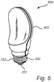
- FIG. 5 illustrates a lighting device 400 according to one embodiment of the present invention.
- the lighting device 400 comprises a base 300 arranged to be mounted in a socket comprising a socket bottom conductor, not shown.
- the lighting device 400 further includes a lighting module 402, arranged on the base 300.
- the lighting module 402 comprises at least one light source, not shown.
- the lighting module 402 is asymmetric and as a consequence the lighting device 400 is rotationally asymmetric.
- the base 300 is the base disclosed above in relation to figures 3 and 4 .
- the base 300 comprises a tubular enclosure 102 and a base bottom conductor 311.
- the base bottom conductor 311 is axially movable, in relation to the tubular enclosure 102, such that the base 300 may be rotated after it is mounted in the socket without reducing or breaking the electrical contact between the base bottom conductor 311 and a socket bottom contact. It is thereby possible to rotationally adjust the position of the lighting device 400 by turning the base 300 in the socket, without reducing the efficiency of lighting device 400.
- the visual appearance, i.e., its rotational position may thereby be tuned by changing the rotational angle of the lighting device 400 in the socket.
- the lighting module 402 may be oriented in a preferred rotational direction.
- a lighting device may be provided comprising a symmetric lighting module, but having a rotationally asymmetric light output. Again, by being able to rotationally adjust the position of the lighting device, by turning the base of the lighting device in the socket, the light emission from the lighting device may be tuned.
- the base 300 may be any base according to the subject matter of the present invention.
- the person skilled in the art realizes that the present invention by no means is limited to the preferred embodiments described above. On the contrary, many modifications and variations are possible within the scope of the appended claims.
- tubular enclosure and the base bottom conductor may consist of the same or different electrically conductive materials.
- the lighting device may comprise various types of light sources.
- the lighting device may be a light emitting diode LED or an electric lamp comprising one or more halogen light sources.
Landscapes
- Engineering & Computer Science (AREA)
- Physics & Mathematics (AREA)
- Microelectronics & Electronic Packaging (AREA)
- Optics & Photonics (AREA)
- General Engineering & Computer Science (AREA)
- Non-Portable Lighting Devices Or Systems Thereof (AREA)
- Arrangement Of Elements, Cooling, Sealing, Or The Like Of Lighting Devices (AREA)
Applications Claiming Priority (2)
| Application Number | Priority Date | Filing Date | Title |
|---|---|---|---|
| EP14167609 | 2014-05-09 | ||
| PCT/EP2015/059767 WO2015169770A1 (en) | 2014-05-09 | 2015-05-05 | Adjustable lamp base |
Publications (2)
| Publication Number | Publication Date |
|---|---|
| EP3140589A1 EP3140589A1 (en) | 2017-03-15 |
| EP3140589B1 true EP3140589B1 (en) | 2018-04-18 |
Family
ID=50687297
Family Applications (1)
| Application Number | Title | Priority Date | Filing Date |
|---|---|---|---|
| EP15722491.6A Not-in-force EP3140589B1 (en) | 2014-05-09 | 2015-05-05 | Adjustable lamp base |
Country Status (5)
| Country | Link |
|---|---|
| US (1) | US10374374B2 (enExample) |
| EP (1) | EP3140589B1 (enExample) |
| JP (1) | JP6592459B2 (enExample) |
| CN (1) | CN106461166B (enExample) |
| WO (1) | WO2015169770A1 (enExample) |
Families Citing this family (3)
| Publication number | Priority date | Publication date | Assignee | Title |
|---|---|---|---|---|
| SE542868C2 (en) | 2019-03-07 | 2020-07-21 | Ikea Supply Ag | Light source and light fitting |
| CN212746038U (zh) * | 2020-06-11 | 2021-03-19 | 东莞市华灯光源有限公司 | 一种防水免焊led灯泡 |
| US20230272886A1 (en) * | 2020-07-27 | 2023-08-31 | Signify Holding B.V. | Lamp screw cap |
Citations (1)
| Publication number | Priority date | Publication date | Assignee | Title |
|---|---|---|---|---|
| US3215972A (en) * | 1962-09-24 | 1965-11-02 | Ernst A Eriksson | Electrical connector |
Family Cites Families (10)
| Publication number | Priority date | Publication date | Assignee | Title |
|---|---|---|---|---|
| US1957821A (en) * | 1931-04-23 | 1934-05-08 | Charles W Dake | Electric light |
| DE202006018985U1 (de) * | 2006-12-15 | 2007-03-29 | Patent-Treuhand-Gesellschaft für elektrische Glühlampen mbH | Lampe mit einem Sockel und mindestens einem lichtemittierenden Halbleiterbauelement |
| CN200986148Y (zh) * | 2006-12-22 | 2007-12-05 | 宁波安迪光电科技有限公司 | 单颗粒led模组化光源装置 |
| KR20100006235A (ko) | 2008-07-09 | 2010-01-19 | (주)다인조형공사 | 조명방향을 조정가능한 조명 기구 |
| KR100914507B1 (ko) | 2009-05-14 | 2009-09-04 | (주)대성전기조명 | Led 조명모듈의 결합장치 |
| KR101102503B1 (ko) * | 2009-12-24 | 2012-01-03 | 주식회사 에스에스라이트 | 조명기구 |
| KR100997891B1 (ko) | 2009-12-24 | 2010-12-02 | (주)에스에스라이트 | 램프 방향성 조절 기능을 구비한 조명기구 |
| US8147267B2 (en) | 2010-09-02 | 2012-04-03 | Xeralux, Inc. | Base for retrofit LED lighting device |
| US8845132B2 (en) * | 2011-02-09 | 2014-09-30 | Differential Energy Products, Llc | Flat LED lamp assembly |
| CN202132757U (zh) | 2011-07-08 | 2012-02-01 | 杭州橄榄树节能科技有限公司 | 一种球形led灯 |
-
2015
- 2015-05-05 WO PCT/EP2015/059767 patent/WO2015169770A1/en not_active Ceased
- 2015-05-05 CN CN201580024218.3A patent/CN106461166B/zh not_active Expired - Fee Related
- 2015-05-05 EP EP15722491.6A patent/EP3140589B1/en not_active Not-in-force
- 2015-05-05 JP JP2016566880A patent/JP6592459B2/ja not_active Expired - Fee Related
- 2015-05-05 US US15/309,687 patent/US10374374B2/en active Active
Patent Citations (1)
| Publication number | Priority date | Publication date | Assignee | Title |
|---|---|---|---|---|
| US3215972A (en) * | 1962-09-24 | 1965-11-02 | Ernst A Eriksson | Electrical connector |
Also Published As
| Publication number | Publication date |
|---|---|
| EP3140589A1 (en) | 2017-03-15 |
| CN106461166A (zh) | 2017-02-22 |
| US10374374B2 (en) | 2019-08-06 |
| CN106461166B (zh) | 2019-07-05 |
| JP2017516264A (ja) | 2017-06-15 |
| US20170149188A1 (en) | 2017-05-25 |
| JP6592459B2 (ja) | 2019-10-16 |
| WO2015169770A1 (en) | 2015-11-12 |
Similar Documents
| Publication | Publication Date | Title |
|---|---|---|
| US7892031B1 (en) | Quick insertion lamp assembly | |
| US8167452B2 (en) | Lighting apparatus | |
| JP5142620B2 (ja) | 照明装置 | |
| EP2354650A2 (en) | Lighting apparatus | |
| JP6009701B2 (ja) | 電球の口金及び電球の口金の組み立て方法 | |
| JP5472635B2 (ja) | 直管形ランプおよび照明器具 | |
| US9371981B2 (en) | LED lamp having stable structure and easy assembly | |
| EP3140589B1 (en) | Adjustable lamp base | |
| US9046223B2 (en) | Light-emitting device | |
| KR101475888B1 (ko) | Led 조명 장치 | |
| US8944835B2 (en) | Electrical connector | |
| TWI771291B (zh) | 管狀發光二極體燈 | |
| KR101652870B1 (ko) | 엘이디 램프용 사이드 캡 및 이와 결합되는 소켓 | |
| US20120286644A1 (en) | Lamp Socket | |
| CN103822178A (zh) | 用于光源领域的旋转帽 | |
| WO2015011636A1 (en) | Carrier for led lamps | |
| US8564182B2 (en) | Lamp having contact members at its surrounding edge, and a lamp holder | |
| KR200482409Y1 (ko) | 조명등 베이스 | |
| JP6465148B2 (ja) | 直管形ランプおよび照明器具 | |
| JP6137564B2 (ja) | 直管形ランプおよび照明器具 | |
| JP5915912B2 (ja) | 直管形ランプおよび照明器具 | |
| JP2020536349A (ja) | 電球用の導電性駆動基板 | |
| NZ745012A (en) | Connector system for lighting assembly | |
| NZ745012B2 (en) | Connector system for lighting assembly |
Legal Events
| Date | Code | Title | Description |
|---|---|---|---|
| PUAI | Public reference made under article 153(3) epc to a published international application that has entered the european phase |
Free format text: ORIGINAL CODE: 0009012 |
|
| 17P | Request for examination filed |
Effective date: 20161209 |
|
| AK | Designated contracting states |
Kind code of ref document: A1 Designated state(s): AL AT BE BG CH CY CZ DE DK EE ES FI FR GB GR HR HU IE IS IT LI LT LU LV MC MK MT NL NO PL PT RO RS SE SI SK SM TR |
|
| AX | Request for extension of the european patent |
Extension state: BA ME |
|
| 17Q | First examination report despatched |
Effective date: 20170314 |
|
| DAV | Request for validation of the european patent (deleted) | ||
| DAX | Request for extension of the european patent (deleted) | ||
| RIN1 | Information on inventor provided before grant (corrected) |
Inventor name: KAANDORP, WOUTER PETRUS |
|
| GRAP | Despatch of communication of intention to grant a patent |
Free format text: ORIGINAL CODE: EPIDOSNIGR1 |
|
| INTG | Intention to grant announced |
Effective date: 20171109 |
|
| GRAS | Grant fee paid |
Free format text: ORIGINAL CODE: EPIDOSNIGR3 |
|
| GRAA | (expected) grant |
Free format text: ORIGINAL CODE: 0009210 |
|
| AK | Designated contracting states |
Kind code of ref document: B1 Designated state(s): AL AT BE BG CH CY CZ DE DK EE ES FI FR GB GR HR HU IE IS IT LI LT LU LV MC MK MT NL NO PL PT RO RS SE SI SK SM TR |
|
| REG | Reference to a national code |
Ref country code: GB Ref legal event code: FG4D |
|
| REG | Reference to a national code |
Ref country code: CH Ref legal event code: EP |
|
| REG | Reference to a national code |
Ref country code: AT Ref legal event code: REF Ref document number: 990884 Country of ref document: AT Kind code of ref document: T Effective date: 20180515 |
|
| REG | Reference to a national code |
Ref country code: IE Ref legal event code: FG4D |
|
| REG | Reference to a national code |
Ref country code: DE Ref legal event code: R096 Ref document number: 602015010146 Country of ref document: DE |
|
| REG | Reference to a national code |
Ref country code: FR Ref legal event code: PLFP Year of fee payment: 4 |
|
| REG | Reference to a national code |
Ref country code: SE Ref legal event code: TRGR |
|
| REG | Reference to a national code |
Ref country code: NL Ref legal event code: MP Effective date: 20180418 |
|
| REG | Reference to a national code |
Ref country code: LT Ref legal event code: MG4D |
|
| PG25 | Lapsed in a contracting state [announced via postgrant information from national office to epo] |
Ref country code: NL Free format text: LAPSE BECAUSE OF FAILURE TO SUBMIT A TRANSLATION OF THE DESCRIPTION OR TO PAY THE FEE WITHIN THE PRESCRIBED TIME-LIMIT Effective date: 20180418 |
|
| PG25 | Lapsed in a contracting state [announced via postgrant information from national office to epo] |
Ref country code: ES Free format text: LAPSE BECAUSE OF FAILURE TO SUBMIT A TRANSLATION OF THE DESCRIPTION OR TO PAY THE FEE WITHIN THE PRESCRIBED TIME-LIMIT Effective date: 20180418 Ref country code: AL Free format text: LAPSE BECAUSE OF FAILURE TO SUBMIT A TRANSLATION OF THE DESCRIPTION OR TO PAY THE FEE WITHIN THE PRESCRIBED TIME-LIMIT Effective date: 20180418 Ref country code: NO Free format text: LAPSE BECAUSE OF FAILURE TO SUBMIT A TRANSLATION OF THE DESCRIPTION OR TO PAY THE FEE WITHIN THE PRESCRIBED TIME-LIMIT Effective date: 20180718 Ref country code: BG Free format text: LAPSE BECAUSE OF FAILURE TO SUBMIT A TRANSLATION OF THE DESCRIPTION OR TO PAY THE FEE WITHIN THE PRESCRIBED TIME-LIMIT Effective date: 20180718 Ref country code: LT Free format text: LAPSE BECAUSE OF FAILURE TO SUBMIT A TRANSLATION OF THE DESCRIPTION OR TO PAY THE FEE WITHIN THE PRESCRIBED TIME-LIMIT Effective date: 20180418 Ref country code: FI Free format text: LAPSE BECAUSE OF FAILURE TO SUBMIT A TRANSLATION OF THE DESCRIPTION OR TO PAY THE FEE WITHIN THE PRESCRIBED TIME-LIMIT Effective date: 20180418 Ref country code: PL Free format text: LAPSE BECAUSE OF FAILURE TO SUBMIT A TRANSLATION OF THE DESCRIPTION OR TO PAY THE FEE WITHIN THE PRESCRIBED TIME-LIMIT Effective date: 20180418 |
|
| PG25 | Lapsed in a contracting state [announced via postgrant information from national office to epo] |
Ref country code: HR Free format text: LAPSE BECAUSE OF FAILURE TO SUBMIT A TRANSLATION OF THE DESCRIPTION OR TO PAY THE FEE WITHIN THE PRESCRIBED TIME-LIMIT Effective date: 20180418 Ref country code: GR Free format text: LAPSE BECAUSE OF FAILURE TO SUBMIT A TRANSLATION OF THE DESCRIPTION OR TO PAY THE FEE WITHIN THE PRESCRIBED TIME-LIMIT Effective date: 20180719 Ref country code: LV Free format text: LAPSE BECAUSE OF FAILURE TO SUBMIT A TRANSLATION OF THE DESCRIPTION OR TO PAY THE FEE WITHIN THE PRESCRIBED TIME-LIMIT Effective date: 20180418 Ref country code: RS Free format text: LAPSE BECAUSE OF FAILURE TO SUBMIT A TRANSLATION OF THE DESCRIPTION OR TO PAY THE FEE WITHIN THE PRESCRIBED TIME-LIMIT Effective date: 20180418 |
|
| RAP2 | Party data changed (patent owner data changed or rights of a patent transferred) |
Owner name: PHILIPS LIGHTING HOLDING B.V. |
|
| REG | Reference to a national code |
Ref country code: CH Ref legal event code: PL |
|
| REG | Reference to a national code |
Ref country code: AT Ref legal event code: MK05 Ref document number: 990884 Country of ref document: AT Kind code of ref document: T Effective date: 20180418 |
|
| REG | Reference to a national code |
Ref country code: DE Ref legal event code: R097 Ref document number: 602015010146 Country of ref document: DE |
|
| REG | Reference to a national code |
Ref country code: BE Ref legal event code: MM Effective date: 20180531 |
|
| PG25 | Lapsed in a contracting state [announced via postgrant information from national office to epo] |
Ref country code: CZ Free format text: LAPSE BECAUSE OF FAILURE TO SUBMIT A TRANSLATION OF THE DESCRIPTION OR TO PAY THE FEE WITHIN THE PRESCRIBED TIME-LIMIT Effective date: 20180418 Ref country code: RO Free format text: LAPSE BECAUSE OF FAILURE TO SUBMIT A TRANSLATION OF THE DESCRIPTION OR TO PAY THE FEE WITHIN THE PRESCRIBED TIME-LIMIT Effective date: 20180418 Ref country code: SK Free format text: LAPSE BECAUSE OF FAILURE TO SUBMIT A TRANSLATION OF THE DESCRIPTION OR TO PAY THE FEE WITHIN THE PRESCRIBED TIME-LIMIT Effective date: 20180418 Ref country code: MC Free format text: LAPSE BECAUSE OF FAILURE TO SUBMIT A TRANSLATION OF THE DESCRIPTION OR TO PAY THE FEE WITHIN THE PRESCRIBED TIME-LIMIT Effective date: 20180418 Ref country code: EE Free format text: LAPSE BECAUSE OF FAILURE TO SUBMIT A TRANSLATION OF THE DESCRIPTION OR TO PAY THE FEE WITHIN THE PRESCRIBED TIME-LIMIT Effective date: 20180418 Ref country code: AT Free format text: LAPSE BECAUSE OF FAILURE TO SUBMIT A TRANSLATION OF THE DESCRIPTION OR TO PAY THE FEE WITHIN THE PRESCRIBED TIME-LIMIT Effective date: 20180418 Ref country code: DK Free format text: LAPSE BECAUSE OF FAILURE TO SUBMIT A TRANSLATION OF THE DESCRIPTION OR TO PAY THE FEE WITHIN THE PRESCRIBED TIME-LIMIT Effective date: 20180418 |
|
| REG | Reference to a national code |
Ref country code: IE Ref legal event code: MM4A |
|
| PLBE | No opposition filed within time limit |
Free format text: ORIGINAL CODE: 0009261 |
|
| STAA | Information on the status of an ep patent application or granted ep patent |
Free format text: STATUS: NO OPPOSITION FILED WITHIN TIME LIMIT |
|
| PG25 | Lapsed in a contracting state [announced via postgrant information from national office to epo] |
Ref country code: SM Free format text: LAPSE BECAUSE OF FAILURE TO SUBMIT A TRANSLATION OF THE DESCRIPTION OR TO PAY THE FEE WITHIN THE PRESCRIBED TIME-LIMIT Effective date: 20180418 Ref country code: CH Free format text: LAPSE BECAUSE OF NON-PAYMENT OF DUE FEES Effective date: 20180531 Ref country code: LI Free format text: LAPSE BECAUSE OF NON-PAYMENT OF DUE FEES Effective date: 20180531 |
|
| RAP2 | Party data changed (patent owner data changed or rights of a patent transferred) |
Owner name: SIGNIFY HOLDING B.V. |
|
| 26N | No opposition filed |
Effective date: 20190121 |
|
| PG25 | Lapsed in a contracting state [announced via postgrant information from national office to epo] |
Ref country code: LU Free format text: LAPSE BECAUSE OF NON-PAYMENT OF DUE FEES Effective date: 20180505 |
|
| PG25 | Lapsed in a contracting state [announced via postgrant information from national office to epo] |
Ref country code: IE Free format text: LAPSE BECAUSE OF NON-PAYMENT OF DUE FEES Effective date: 20180505 |
|
| PG25 | Lapsed in a contracting state [announced via postgrant information from national office to epo] |
Ref country code: SI Free format text: LAPSE BECAUSE OF FAILURE TO SUBMIT A TRANSLATION OF THE DESCRIPTION OR TO PAY THE FEE WITHIN THE PRESCRIBED TIME-LIMIT Effective date: 20180418 Ref country code: BE Free format text: LAPSE BECAUSE OF NON-PAYMENT OF DUE FEES Effective date: 20180531 |
|
| PG25 | Lapsed in a contracting state [announced via postgrant information from national office to epo] |
Ref country code: MT Free format text: LAPSE BECAUSE OF NON-PAYMENT OF DUE FEES Effective date: 20180505 |
|
| PG25 | Lapsed in a contracting state [announced via postgrant information from national office to epo] |
Ref country code: TR Free format text: LAPSE BECAUSE OF FAILURE TO SUBMIT A TRANSLATION OF THE DESCRIPTION OR TO PAY THE FEE WITHIN THE PRESCRIBED TIME-LIMIT Effective date: 20180418 |
|
| PG25 | Lapsed in a contracting state [announced via postgrant information from national office to epo] |
Ref country code: PT Free format text: LAPSE BECAUSE OF FAILURE TO SUBMIT A TRANSLATION OF THE DESCRIPTION OR TO PAY THE FEE WITHIN THE PRESCRIBED TIME-LIMIT Effective date: 20180418 |
|
| PG25 | Lapsed in a contracting state [announced via postgrant information from national office to epo] |
Ref country code: HU Free format text: LAPSE BECAUSE OF FAILURE TO SUBMIT A TRANSLATION OF THE DESCRIPTION OR TO PAY THE FEE WITHIN THE PRESCRIBED TIME-LIMIT; INVALID AB INITIO Effective date: 20150505 Ref country code: CY Free format text: LAPSE BECAUSE OF FAILURE TO SUBMIT A TRANSLATION OF THE DESCRIPTION OR TO PAY THE FEE WITHIN THE PRESCRIBED TIME-LIMIT Effective date: 20180418 Ref country code: MK Free format text: LAPSE BECAUSE OF NON-PAYMENT OF DUE FEES Effective date: 20180418 |
|
| PG25 | Lapsed in a contracting state [announced via postgrant information from national office to epo] |
Ref country code: IS Free format text: LAPSE BECAUSE OF FAILURE TO SUBMIT A TRANSLATION OF THE DESCRIPTION OR TO PAY THE FEE WITHIN THE PRESCRIBED TIME-LIMIT Effective date: 20180818 |
|
| REG | Reference to a national code |
Ref country code: DE Ref legal event code: R081 Ref document number: 602015010146 Country of ref document: DE Owner name: SIGNIFY HOLDING B.V., NL Free format text: FORMER OWNER: PHILIPS LIGHTING HOLDING B.V., EINDHOVEN, NL |
|
| P01 | Opt-out of the competence of the unified patent court (upc) registered |
Effective date: 20230421 |
|
| PGFP | Annual fee paid to national office [announced via postgrant information from national office to epo] |
Ref country code: IT Payment date: 20230525 Year of fee payment: 9 Ref country code: FR Payment date: 20230523 Year of fee payment: 9 |
|
| PGFP | Annual fee paid to national office [announced via postgrant information from national office to epo] |
Ref country code: SE Payment date: 20230524 Year of fee payment: 9 |
|
| PGFP | Annual fee paid to national office [announced via postgrant information from national office to epo] |
Ref country code: GB Payment date: 20230523 Year of fee payment: 9 |
|
| PGFP | Annual fee paid to national office [announced via postgrant information from national office to epo] |
Ref country code: DE Payment date: 20230726 Year of fee payment: 9 |
|
| REG | Reference to a national code |
Ref country code: DE Ref legal event code: R119 Ref document number: 602015010146 Country of ref document: DE |
|
| REG | Reference to a national code |
Ref country code: SE Ref legal event code: EUG |
|
| GBPC | Gb: european patent ceased through non-payment of renewal fee |
Effective date: 20240505 |
|
| PG25 | Lapsed in a contracting state [announced via postgrant information from national office to epo] |
Ref country code: DE Free format text: LAPSE BECAUSE OF NON-PAYMENT OF DUE FEES Effective date: 20241203 |
|
| PG25 | Lapsed in a contracting state [announced via postgrant information from national office to epo] |
Ref country code: FR Free format text: LAPSE BECAUSE OF NON-PAYMENT OF DUE FEES Effective date: 20240531 |
|
| PG25 | Lapsed in a contracting state [announced via postgrant information from national office to epo] |
Ref country code: GB Free format text: LAPSE BECAUSE OF NON-PAYMENT OF DUE FEES Effective date: 20240505 Ref country code: IT Free format text: LAPSE BECAUSE OF NON-PAYMENT OF DUE FEES Effective date: 20240505 |
|
| PG25 | Lapsed in a contracting state [announced via postgrant information from national office to epo] |
Ref country code: SE Free format text: LAPSE BECAUSE OF NON-PAYMENT OF DUE FEES Effective date: 20240506 |