EP3140160B1 - Rearview device with exposed carrier plate - Google Patents
Rearview device with exposed carrier plate Download PDFInfo
- Publication number
- EP3140160B1 EP3140160B1 EP15789475.9A EP15789475A EP3140160B1 EP 3140160 B1 EP3140160 B1 EP 3140160B1 EP 15789475 A EP15789475 A EP 15789475A EP 3140160 B1 EP3140160 B1 EP 3140160B1
- Authority
- EP
- European Patent Office
- Prior art keywords
- carrier plate
- rearview
- peripheral wall
- back side
- device housing
- Prior art date
- Legal status (The legal status is an assumption and is not a legal conclusion. Google has not performed a legal analysis and makes no representation as to the accuracy of the status listed.)
- Active
Links
Images


Classifications
-
- B—PERFORMING OPERATIONS; TRANSPORTING
- B60—VEHICLES IN GENERAL
- B60R—VEHICLES, VEHICLE FITTINGS, OR VEHICLE PARTS, NOT OTHERWISE PROVIDED FOR
- B60R1/00—Optical viewing arrangements; Real-time viewing arrangements for drivers or passengers using optical image capturing systems, e.g. cameras or video systems specially adapted for use in or on vehicles
- B60R1/02—Rear-view mirror arrangements
- B60R1/04—Rear-view mirror arrangements mounted inside vehicle
-
- B—PERFORMING OPERATIONS; TRANSPORTING
- B60—VEHICLES IN GENERAL
- B60R—VEHICLES, VEHICLE FITTINGS, OR VEHICLE PARTS, NOT OTHERWISE PROVIDED FOR
- B60R1/00—Optical viewing arrangements; Real-time viewing arrangements for drivers or passengers using optical image capturing systems, e.g. cameras or video systems specially adapted for use in or on vehicles
- B60R1/02—Rear-view mirror arrangements
- B60R1/08—Rear-view mirror arrangements involving special optical features, e.g. avoiding blind spots, e.g. convex mirrors; Side-by-side associations of rear-view and other mirrors
- B60R1/083—Anti-glare mirrors, e.g. "day-night" mirrors
- B60R1/088—Anti-glare mirrors, e.g. "day-night" mirrors using a cell of electrically changeable optical characteristic, e.g. liquid-crystal or electrochromic mirrors
-
- G—PHYSICS
- G02—OPTICS
- G02F—OPTICAL DEVICES OR ARRANGEMENTS FOR THE CONTROL OF LIGHT BY MODIFICATION OF THE OPTICAL PROPERTIES OF THE MEDIA OF THE ELEMENTS INVOLVED THEREIN; NON-LINEAR OPTICS; FREQUENCY-CHANGING OF LIGHT; OPTICAL LOGIC ELEMENTS; OPTICAL ANALOGUE/DIGITAL CONVERTERS
- G02F1/00—Devices or arrangements for the control of the intensity, colour, phase, polarisation or direction of light arriving from an independent light source, e.g. switching, gating or modulating; Non-linear optics
- G02F1/01—Devices or arrangements for the control of the intensity, colour, phase, polarisation or direction of light arriving from an independent light source, e.g. switching, gating or modulating; Non-linear optics for the control of the intensity, phase, polarisation or colour
- G02F1/15—Devices or arrangements for the control of the intensity, colour, phase, polarisation or direction of light arriving from an independent light source, e.g. switching, gating or modulating; Non-linear optics for the control of the intensity, phase, polarisation or colour based on an electrochromic effect
- G02F1/153—Constructional details
- G02F1/1533—Constructional details structural features not otherwise provided for
-
- G—PHYSICS
- G02—OPTICS
- G02F—OPTICAL DEVICES OR ARRANGEMENTS FOR THE CONTROL OF LIGHT BY MODIFICATION OF THE OPTICAL PROPERTIES OF THE MEDIA OF THE ELEMENTS INVOLVED THEREIN; NON-LINEAR OPTICS; FREQUENCY-CHANGING OF LIGHT; OPTICAL LOGIC ELEMENTS; OPTICAL ANALOGUE/DIGITAL CONVERTERS
- G02F1/00—Devices or arrangements for the control of the intensity, colour, phase, polarisation or direction of light arriving from an independent light source, e.g. switching, gating or modulating; Non-linear optics
- G02F1/01—Devices or arrangements for the control of the intensity, colour, phase, polarisation or direction of light arriving from an independent light source, e.g. switching, gating or modulating; Non-linear optics for the control of the intensity, phase, polarisation or colour
- G02F1/15—Devices or arrangements for the control of the intensity, colour, phase, polarisation or direction of light arriving from an independent light source, e.g. switching, gating or modulating; Non-linear optics for the control of the intensity, phase, polarisation or colour based on an electrochromic effect
- G02F1/153—Constructional details
- G02F1/157—Structural association of cells with optical devices, e.g. reflectors or illuminating devices
Definitions
- the present disclosure generally relates to a rearview device, and more particularly to a rearview device with an exposed carrier plate for a vehicle.
- EP 2 485 921 A1 describes a rearview mirror assembly having a bezel portion that is attached to the forward or front edge region of a mirror casing, wherein the bezel portion is generally coplanar or flush with a side wall of the mirror casing, when the bezel is attached to the mirror casing.
- DE 14 30 686 A1 describes a rearview mirror for vehicles of all types, comprising a housing defining a chamber for receiving an optically dense light attenuating medium, and a transparent first plate forming a window for the housing comprising a light reflective front surface of relatively low light reflectance.
- a rear surface located within the chamber and having an inner second plate disposed within the chamber having a light reflecting surface of relatively high light reflectivity facing the rear surface of the first plate.
- One aspect of the present disclosure includes a rearview device having a front element defining a first surface and a second surface.
- a rear element defines a third surface and a fourth surface.
- An electro-optic material is located between the front element and the rear element.
- a carrier plate includes a front side, a back side, and a peripheral wall. The front side is disposed proximate the fourth surface and the peripheral wall is operably coupled with a peripheral edge of the second surface.
- a device housing is operably coupled to the back side of the carrier plate. The peripheral wall and a portion of the back side of the carrier plate extend beyond the device housing and are externally exposed.
- a rearview device having a display device that includes a peripheral edge.
- a carrier plate includes a back side and a peripheral wall.
- the peripheral wall is operably coupled with the peripheral edge of the display device and is generally flush therewith to create a smooth transition from the peripheral edge of the display device to the peripheral wall of the carrier plate.
- a device housing is proximate the back side of the carrier plate. The peripheral wall and a portion of the back side of the carrier plate extend beyond the device housing and are externally exposed.
- An engagement wall extends generally orthogonal to the back side of the peripheral wall and operably couples the carrier plate with the device housing.
- Yet another aspect of the present disclosure includes a rearview device having a display device that includes a peripheral edge.
- a carrier plate includes a back side and a peripheral wall.
- the peripheral wall is operably coupled with the peripheral edge and is generally flush therewith to create a generally smooth transition from the peripheral edge of the display device to the peripheral wall of the carrier plate.
- a device housing is operably coupled to the back side of the carrier plate. The peripheral wall and a portion of the back side of the carrier plate extend beyond the device housing and are externally exposed.
- Still yet another aspect of the present disclosure includes a rearview device having a display device that includes a peripheral edge.
- a carrier plate includes a back side and a peripheral wall.
- the peripheral wall is operably coupled with the peripheral edge and is generally flush therewith to create a generally smooth transition from the peripheral edge of the display device to the peripheral wall of the carrier plate.
- a device housing is operably coupled to the back side of the carrier plate. The peripheral wall and a portion of the back side of the carrier plate extend beyond the device housing and are externally exposed.
- a seal may be disposed between the carrier plate and a front element.
- the terms "upper,” “lower,” “right,” “left,” “rear,” “front,” “vertical,” “horizontal,” and derivatives thereof shall relate to the disclosure as oriented in FIG. 1 .
- the disclosure may assume various alternative orientations, except where expressly specified to the contrary.
- the specific devices and processes illustrated in the attached drawings, and described in the following specification are simply exemplary embodiments of the inventive concepts defined in the appended claims. Hence, specific dimensions and other physical characteristics relating to the embodiments disclosed herein are not to be considered as limiting, unless the claims expressly state otherwise.
- the term "and/or,” when used in a list of two or more items, means that any one of the listed items can be employed by itself, or any combination of two or more of the listed items can be employed.
- the composition can contain A alone; B alone; C alone; A and B in combination; A and C in combination; B and C in combination; or A, B, and C in combination.
- reference numeral 10 generally designates a rearview device having a front element 12 defining a first surface 14 and a second surface 16.
- a rear element 18 defines a third surface 20 and a fourth surface 22.
- An electro-optic material 24, such as an electrochromic material, is located between the front element 12 and the rear element 18.
- a carrier plate 26 includes a front side 28, a back side 30, and a peripheral wall 32. The front side 28 is disposed proximate the fourth surface 22.
- a device housing 36 is operably coupled to the back side 30 of the carrier plate 26. The peripheral wall 32 and an outer portion 38 of the back side 30 of the carrier plate 26 extend beyond the device housing 36 and are externally exposed.
- the rearview device 10 is generally configured for installation on a front windshield of a vehicle.
- the rearview device 10 includes a mount 50 configured for engagement with the inside surface of the windshield.
- the mount 50 includes a windshield connector 52 defining a socket 54 configured to engage a ball 56 ( FIG. 4 ) of a device support 58.
- the ball 56 and socket 54 can be disposed inside or outside of the device housing 36.
- the mount 50 provides for a range of movement of the rearview device 10 relative to the windshield. Further, it is also contemplated that the mount 50 can be operably coupled with the back side 30 of the carrier plate 26 inside the device housing 36.
- the socket 54 may be similar to that set forth in U.S. Patent Application Publication No.
- the device support 58 extends into and is received by a recess 60 defined in a rear portion 62 of the device housing 36 and provides one or more of an electrical, mechanical, and data connection to the rearview device 10.
- the height and width of the device housing 36 is considerably smaller than the height and width of the carrier plate 26, the front element 12, and the rear element 18.
- the device housing 36 mounts to the back side 30 of the carrier plate 26. More specifically, the device housing 36 mounts to a fastening arrangement in the form of an engagement wall 66 extending from the back side 30 of the carrier plate 26.
- the fastening arrangement is disposed on an inside surface of the device housing 36. Accordingly, the outer portion 38 of the back side 30 of the carrier plate 26 is left exposed.
- the outer portion 38 of the carrier plate 26 may include a similar or dissimilar texture and color to the device housing 36. As illustrated in FIGS. 1 , 3, and 4 , the carrier plate 26 extends past the device housing 36 approximately one inch.
- the rearwardly extending engagement wall 66 of the carrier plate 26 is configured for mechanical attachment with the device housing 36.
- the device housing 36 is generally configured to house, support, and protect electrical components, including at least one circuit board.
- the device housing 36 is slightly tapered and configured for engagement with the engagement wall 66 disposed on the back side 30 of the carrier plate 26. It is generally contemplated that the engagement wall 66 may engage an inside of the device housing 36 or an outside of the device housing 36 during assembly. It is also contemplated that the carrier plate 26 could be integrally formed or molded with the device housing 36 as a single piece.
- the front element 12 is exposed while the rear element 18 is positioned behind the front element 12.
- the front element 12 has a greater height and width than the rear element 18 and also includes a rounded front edge 70.
- the rounded front edge 70 provides a smooth and aesthetically pleasing look to the rearview device 10.
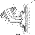
- the carrier plate 26 includes a rounded rear transition portion 72 similar to the rounded front edge 70 of the front element 12. As illustrated in FIG. 6 , the carrier plate 26 wraps around the rear element 18 and abuts the second surface 16 of the front element 12. This construction provides a uniform and smooth transition from the carrier plate 26 to the front element 12 and encloses the rear element 18 and also conceals the rear element 18 from view.
- the carrier plate 26 can abut the fourth surface 22 of the rear element 18. In this instance, a periphery of the rear element 18 may be exposed. It is also contemplated that a seal 80 may be disposed between the carrier plate 26 and the front element 12 that maintains the front element 12 and the carrier plate 26 coupled.
- the rounded front edge 70 of the front element 12 may be molded, ground, or otherwise formed on the peripheral front edge of the front element 12. It is generally contemplated that the radius of curvature of the front element 12 may mimic or otherwise be similar to the rounded rear transition portion 72 between the peripheral wall 32 and the back side 30 of the carrier plate 26. Accordingly, a consistent feel between the front element 12 and the carrier plate 26 is provided to a user adjusting the rearview device 10.
- the carrier plate 26 and the front element 12 may include different peripheral constructions.
- the peripheral wall 32 of the carrier plate 26 may include a transition portion having an angled wall rather than a rounded wall.
- a knurled or otherwise rough surface may be formed on the peripheral wall 32 that assists a user in grasping the rearview device 10 and adjusting the same prior to or during travel.
- the rounded front edge 70 of the front element 12 may be smooth, frosted, etc. to complement the feel and appearance of the carrier plate 26.
- the rear element 18 will be spaced a predetermined distance from an inside surface of the carrier plate 26. However, it is also contemplated that the rear element 18 may be in abutting contact with the inside surface of the carrier plate 26 at the peripheral wall 32. Such construction may aid in properly locating the carrier plate 26 during manufacturing.
- male and female adapters 86, 88 may operably couple circuit boards 90 with the vehicle. In an embodiment, the male adapter 86 disposed on the ends of wires 92 is coupled with the female adapter 88 on the circuit boards 90.
- the wires 92 extend through the device housing 36 and the mount 50 and ultimately to a control center, such as a vehicle controller area network (CAN) bus.
- a control center such as a vehicle controller area network (CAN) bus.
- the engagement wall 66 is integral with the carrier plate 26 and extends rearwardly therefrom at a generally orthogonal angle thereto.
- the engagement wall 66 may extend in a variety of other angles from the carrier plate 26.
- the engagement wall 66 may extend from the device housing 36 into secure engagement with slots defined on the back side 30 of the carrier plate 26. It is contemplated that the engagement wall 66 may extend around all, substantially all, or some of the inside surface of the device housing 36.
- the device housing 36 and the carrier plate 26 may be generally opaque, translucent, or transparent. Regardless, it is generally contemplated that a majority of the electrical components used to operate the rearview device 10 are disposed within the device housing 36 and behind the rear element 18 of the rearview device 10 after assembly.
- the recess 60 in the device housing 36 may include at least one aperture 100 configured to relay power and/or data lines therethrough to the circuits boards disposed in the device housing 36. It is contemplated that the data and/or power lines will extend from the circuit boards 90 through the apertures defined in the recess 60 and ultimately through the device support 58 and ball 56 of the mount 50.
- the carrier plate 26 may be configured to extend forward past the second surface 16 of the front element 12.
- the carrier plate 26 includes a framed ring design.
- a peripheral hiding layer for example a chrome ring, is positioned on the second surface 16 to hide electrical contacts in communication with the electro-optic material 24 disposed between the front element 12 and the rear element 18.
- the peripheral walls 32 of the carrier plate 26 include a forward rounded portion 110 that round to a forward, inward edge that is flush with, or nearly flush with, the first surface 14 of the front element 12.
- the rear element 18 is generally concealed between the carrier plate 26 and the front element 12.
- the peripheral wall 32 of the carrier plate 26 conceals the peripheral edge of both the front element 12 and the rear element 18.
- the present disclosure may be used with a rearview assembly such as that described in U.S. Patent Nos. 8,925,891 ; 8,814,373 ; 8,201,800 ; and 8,210,695 ; U.S. Patent Application Publication Nos. 2014/0063630 and 2012/0327234 ; and U.S. Provisional Patent Application Nos. 61/709,716 ; 61/707,676 ; and 61/704,869 , which are hereby incorporated herein by reference in their entirety. Further, the present disclosure may be used with a rearview packaging assembly such as that described in U.S. Patent Nos.
- the term "coupled” in all of its forms, couple, coupling, coupled, etc. generally means the joining of two components (electrical or mechanical) directly or indirectly to one another. Such joining may be stationary in nature or movable in nature. Such joining may be achieved with the two components (electrical or mechanical) and any additional intermediate members being integrally formed as a single unitary body with one another or with the two components. Such joining may be permanent in nature or may be removable or releasable in nature unless otherwise stated.
- elements shown as integrally formed may be constructed of multiple parts or elements shown as multiple parts may be integrally formed, the operation of the interfaces may be reversed or otherwise varied, the length or width of the structures and/or members or connector or other elements of the system may be varied, the nature or number of adjustment positions provided between the elements may be varied.
- the elements and/or assemblies of the system may be constructed from any of a wide variety of materials that provide sufficient strength or durability, in any of a wide variety of colors, textures, and combinations. Accordingly, all such modifications are intended to be included within the scope of the present innovations. Other substitutions, modifications, changes, and omissions may be made in the design, operating conditions, and arrangement of the desired and other exemplary embodiments without departing from the spirit of the present innovations.
Landscapes
- Physics & Mathematics (AREA)
- Engineering & Computer Science (AREA)
- Nonlinear Science (AREA)
- Multimedia (AREA)
- Mechanical Engineering (AREA)
- Optics & Photonics (AREA)
- General Physics & Mathematics (AREA)
- Chemical & Material Sciences (AREA)
- Crystallography & Structural Chemistry (AREA)
- Rear-View Mirror Devices That Are Mounted On The Exterior Of The Vehicle (AREA)
- Casings For Electric Apparatus (AREA)
- Fittings On The Vehicle Exterior For Carrying Loads, And Devices For Holding Or Mounting Articles (AREA)
- Electrochromic Elements, Electrophoresis, Or Variable Reflection Or Absorption Elements (AREA)
Applications Claiming Priority (2)
| Application Number | Priority Date | Filing Date | Title |
|---|---|---|---|
| US201461990480P | 2014-05-08 | 2014-05-08 | |
| PCT/US2015/029904 WO2015172032A1 (en) | 2014-05-08 | 2015-05-08 | Rearview device with exposed carrier plate |
Publications (3)
| Publication Number | Publication Date |
|---|---|
| EP3140160A1 EP3140160A1 (en) | 2017-03-15 |
| EP3140160A4 EP3140160A4 (en) | 2017-06-21 |
| EP3140160B1 true EP3140160B1 (en) | 2019-03-13 |
Family
ID=54367095
Family Applications (1)
| Application Number | Title | Priority Date | Filing Date |
|---|---|---|---|
| EP15789475.9A Active EP3140160B1 (en) | 2014-05-08 | 2015-05-08 | Rearview device with exposed carrier plate |
Country Status (6)
| Country | Link |
|---|---|
| US (1) | US9545882B2 (ja) |
| EP (1) | EP3140160B1 (ja) |
| JP (2) | JP2017515747A (ja) |
| KR (1) | KR101729000B1 (ja) |
| CN (1) | CN106458095A (ja) |
| WO (1) | WO2015172032A1 (ja) |
Families Citing this family (7)
| Publication number | Priority date | Publication date | Assignee | Title |
|---|---|---|---|---|
| WO2010124064A1 (en) | 2009-04-23 | 2010-10-28 | Magna Mirrors Of America, Inc. | Mirror assembly for vehicle |
| US9174578B2 (en) | 2013-04-22 | 2015-11-03 | Magna Mirrors Of America, Inc. | Interior rearview mirror assembly |
| US11046251B2 (en) | 2014-09-19 | 2021-06-29 | Magna Mirrors Of America, Inc. | Interior rearview mirror with GDO module |
| WO2017096030A1 (en) * | 2015-12-04 | 2017-06-08 | Gentex Corporation | Tight bezel-to-glass fit mirror assembly |
| US10850667B2 (en) * | 2017-05-04 | 2020-12-01 | Magna Mirrors Of America | Interior rearview mirror assembly |
| US11485289B2 (en) * | 2020-04-08 | 2022-11-01 | Magna Mirrors Of America, Inc. | Vehicular rearview mirror assembly |
| USD1001700S1 (en) * | 2021-12-30 | 2023-10-17 | Gentex Corporation | Rearview mirror for a vehicle |
Citations (1)
| Publication number | Priority date | Publication date | Assignee | Title |
|---|---|---|---|---|
| DE1430686A1 (de) * | 1961-12-01 | 1968-11-28 | Chrysler Corp | Spiegelaufbau |
Family Cites Families (24)
| Publication number | Priority date | Publication date | Assignee | Title |
|---|---|---|---|---|
| JPS5124029Y2 (ja) * | 1973-02-23 | 1976-06-19 | ||
| JPS5730639A (en) * | 1980-07-31 | 1982-02-18 | Ichikoh Ind Ltd | Anti-glare mirror device |
| JPH0467543U (ja) * | 1990-10-19 | 1992-06-16 | ||
| JPH04123844U (ja) * | 1991-04-25 | 1992-11-10 | 市光工業株式会社 | インサイドミラー |
| US5649756A (en) * | 1991-09-13 | 1997-07-22 | Donnelly Corporation | Rearview mirror with lighting assembly |
| JP3286553B2 (ja) * | 1997-03-17 | 2002-05-27 | 株式会社村上開明堂 | 防眩インナーミラー |
| DE19903378A1 (de) | 1999-01-28 | 2000-08-24 | Mekra Lang Gmbh & Co Kg | Rückspiegel für Kraftfahrzeuge |
| KR200200813Y1 (ko) * | 2000-05-19 | 2000-10-16 | 김우재 | 자동차용 실내 후사경 |
| US6467919B1 (en) * | 2001-11-02 | 2002-10-22 | Gentex Corporation | Mirror with split ball mount and hold-open device |
| US8004741B2 (en) * | 2004-02-27 | 2011-08-23 | Gentex Corporation | Vehicular rearview mirror elements and assemblies incorporating these elements |
| US7121028B2 (en) * | 2002-12-09 | 2006-10-17 | U-Haul International, Inc. | Method and apparatus for converting a rearview mirror into a dedicated information display |
| US7221363B2 (en) * | 2003-02-12 | 2007-05-22 | Gentex Corporation | Vehicle information displays |
| CN101738812B (zh) * | 2003-05-06 | 2013-10-23 | 金泰克斯公司 | 车辆后视镜元件及安装有这些元件的组合件 |
| US20050128610A1 (en) * | 2003-11-03 | 2005-06-16 | Parker Brian R. | Rearview mirror assembly including a housing having a wiring cover |
| FR2874100B1 (fr) * | 2004-08-04 | 2006-09-29 | Saint Gobain | Systeme electrochimique comportant au moins une zone de margeage partiel |
| JP2006103620A (ja) * | 2004-10-08 | 2006-04-20 | Ichikoh Ind Ltd | 車両用ミラー装置 |
| JP2006103623A (ja) * | 2004-10-08 | 2006-04-20 | Ichikoh Ind Ltd | 防眩タイプの車両用インサイドミラー装置 |
| US8201800B2 (en) * | 2008-08-06 | 2012-06-19 | Gentex Corporation | Two ball mount with wiring passage |
| US8451332B2 (en) * | 2009-03-23 | 2013-05-28 | Magna Mirrors Of America, Inc. | Interior mirror assembly with adjustable mounting assembly |
| WO2011044312A1 (en) * | 2009-10-07 | 2011-04-14 | Magna Mirrors Of America, Inc. | Frameless interior rearview mirror assembly |
| JP5584096B2 (ja) * | 2010-11-09 | 2014-09-03 | 太平洋工業株式会社 | 車両用樹脂成形品の製造方法 |
| CN202147633U (zh) * | 2011-07-07 | 2012-02-22 | 华德塑料制品有限公司 | 嵌入式无边内后视镜 |
| CN203005254U (zh) * | 2012-10-08 | 2013-06-19 | 深圳市格比特科技有限公司 | 轻触式后视镜行驶仪 |
| US9174578B2 (en) * | 2013-04-22 | 2015-11-03 | Magna Mirrors Of America, Inc. | Interior rearview mirror assembly |
-
2015
- 2015-05-08 US US14/707,148 patent/US9545882B2/en active Active
- 2015-05-08 EP EP15789475.9A patent/EP3140160B1/en active Active
- 2015-05-08 CN CN201580024071.8A patent/CN106458095A/zh active Pending
- 2015-05-08 WO PCT/US2015/029904 patent/WO2015172032A1/en active Application Filing
- 2015-05-08 JP JP2016569054A patent/JP2017515747A/ja active Pending
- 2015-05-08 KR KR1020167031473A patent/KR101729000B1/ko active IP Right Grant
-
2018
- 2018-03-20 JP JP2018052750A patent/JP6657282B2/ja active Active
Patent Citations (1)
| Publication number | Priority date | Publication date | Assignee | Title |
|---|---|---|---|---|
| DE1430686A1 (de) * | 1961-12-01 | 1968-11-28 | Chrysler Corp | Spiegelaufbau |
Also Published As
| Publication number | Publication date |
|---|---|
| CN106458095A (zh) | 2017-02-22 |
| EP3140160A1 (en) | 2017-03-15 |
| KR101729000B1 (ko) | 2017-04-21 |
| WO2015172032A1 (en) | 2015-11-12 |
| EP3140160A4 (en) | 2017-06-21 |
| JP6657282B2 (ja) | 2020-03-04 |
| KR20160134862A (ko) | 2016-11-23 |
| JP2018090252A (ja) | 2018-06-14 |
| US9545882B2 (en) | 2017-01-17 |
| JP2017515747A (ja) | 2017-06-15 |
| US20150321611A1 (en) | 2015-11-12 |
Similar Documents
| Publication | Publication Date | Title |
|---|---|---|
| EP3140160B1 (en) | Rearview device with exposed carrier plate | |
| USD850695S1 (en) | Lighting fixture | |
| US10343608B2 (en) | Rearview assembly | |
| USD905880S1 (en) | Headlamp for an automobile | |
| USD851295S1 (en) | Rear combination lamp for automobile | |
| USD905879S1 (en) | Headlamp for automobile | |
| USD905882S1 (en) | Rear combination lamp for an automobile | |
| USD880739S1 (en) | Rear combination lamp for an automobile | |
| USD897010S1 (en) | Headlight for an automobile | |
| USD851294S1 (en) | Rear combination lamp for automobile | |
| USD951499S1 (en) | Rear combination lamp for automobile | |
| USD917744S1 (en) | Rear combination lamp for an automobile | |
| US20130187017A1 (en) | Rearview assembly with interchangeable rearward viewing device | |
| USD870933S1 (en) | Headlamp for an automobile | |
| USD933864S1 (en) | Rear combination lamp for automobile | |
| USD581909S1 (en) | Car antenna | |
| EP3368375B1 (en) | Rearview device | |
| USD934462S1 (en) | Front combination lamp for automobile | |
| USD897009S1 (en) | Headlight for an automobile | |
| USD852996S1 (en) | Headlamp for an automobile | |
| USD843027S1 (en) | Headlamp for an automobile | |
| USD833654S1 (en) | Headlamp for an automobile | |
| USD917743S1 (en) | Headlamp for an automobile | |
| US10971830B2 (en) | Low profile connector with spring contacts | |
| USD917742S1 (en) | Front combination lamp for an automobile |
Legal Events
| Date | Code | Title | Description |
|---|---|---|---|
| STAA | Information on the status of an ep patent application or granted ep patent |
Free format text: STATUS: THE INTERNATIONAL PUBLICATION HAS BEEN MADE |
|
| PUAI | Public reference made under article 153(3) epc to a published international application that has entered the european phase |
Free format text: ORIGINAL CODE: 0009012 |
|
| STAA | Information on the status of an ep patent application or granted ep patent |
Free format text: STATUS: REQUEST FOR EXAMINATION WAS MADE |
|
| 17P | Request for examination filed |
Effective date: 20161208 |
|
| AK | Designated contracting states |
Kind code of ref document: A1 Designated state(s): AL AT BE BG CH CY CZ DE DK EE ES FI FR GB GR HR HU IE IS IT LI LT LU LV MC MK MT NL NO PL PT RO RS SE SI SK SM TR |
|
| AX | Request for extension of the european patent |
Extension state: BA ME |
|
| A4 | Supplementary search report drawn up and despatched |
Effective date: 20170522 |
|
| RIC1 | Information provided on ipc code assigned before grant |
Ipc: B60R 1/04 20060101AFI20170516BHEP Ipc: B60R 1/08 20060101ALI20170516BHEP |
|
| DAV | Request for validation of the european patent (deleted) | ||
| DAX | Request for extension of the european patent (deleted) | ||
| STAA | Information on the status of an ep patent application or granted ep patent |
Free format text: STATUS: EXAMINATION IS IN PROGRESS |
|
| 17Q | First examination report despatched |
Effective date: 20180424 |
|
| GRAP | Despatch of communication of intention to grant a patent |
Free format text: ORIGINAL CODE: EPIDOSNIGR1 |
|
| STAA | Information on the status of an ep patent application or granted ep patent |
Free format text: STATUS: GRANT OF PATENT IS INTENDED |
|
| INTG | Intention to grant announced |
Effective date: 20180927 |
|
| GRAS | Grant fee paid |
Free format text: ORIGINAL CODE: EPIDOSNIGR3 |
|
| GRAA | (expected) grant |
Free format text: ORIGINAL CODE: 0009210 |
|
| STAA | Information on the status of an ep patent application or granted ep patent |
Free format text: STATUS: THE PATENT HAS BEEN GRANTED |
|
| AK | Designated contracting states |
Kind code of ref document: B1 Designated state(s): AL AT BE BG CH CY CZ DE DK EE ES FI FR GB GR HR HU IE IS IT LI LT LU LV MC MK MT NL NO PL PT RO RS SE SI SK SM TR |
|
| REG | Reference to a national code |
Ref country code: GB Ref legal event code: FG4D |
|
| REG | Reference to a national code |
Ref country code: CH Ref legal event code: EP Ref country code: AT Ref legal event code: REF Ref document number: 1107260 Country of ref document: AT Kind code of ref document: T Effective date: 20190315 |
|
| REG | Reference to a national code |
Ref country code: IE Ref legal event code: FG4D |
|
| REG | Reference to a national code |
Ref country code: DE Ref legal event code: R096 Ref document number: 602015026467 Country of ref document: DE |
|
| REG | Reference to a national code |
Ref country code: NL Ref legal event code: MP Effective date: 20190313 |
|
| REG | Reference to a national code |
Ref country code: LT Ref legal event code: MG4D |
|
| PG25 | Lapsed in a contracting state [announced via postgrant information from national office to epo] |
Ref country code: FI Free format text: LAPSE BECAUSE OF FAILURE TO SUBMIT A TRANSLATION OF THE DESCRIPTION OR TO PAY THE FEE WITHIN THE PRESCRIBED TIME-LIMIT Effective date: 20190313 Ref country code: LT Free format text: LAPSE BECAUSE OF FAILURE TO SUBMIT A TRANSLATION OF THE DESCRIPTION OR TO PAY THE FEE WITHIN THE PRESCRIBED TIME-LIMIT Effective date: 20190313 Ref country code: SE Free format text: LAPSE BECAUSE OF FAILURE TO SUBMIT A TRANSLATION OF THE DESCRIPTION OR TO PAY THE FEE WITHIN THE PRESCRIBED TIME-LIMIT Effective date: 20190313 Ref country code: NO Free format text: LAPSE BECAUSE OF FAILURE TO SUBMIT A TRANSLATION OF THE DESCRIPTION OR TO PAY THE FEE WITHIN THE PRESCRIBED TIME-LIMIT Effective date: 20190613 |
|
| PG25 | Lapsed in a contracting state [announced via postgrant information from national office to epo] |
Ref country code: NL Free format text: LAPSE BECAUSE OF FAILURE TO SUBMIT A TRANSLATION OF THE DESCRIPTION OR TO PAY THE FEE WITHIN THE PRESCRIBED TIME-LIMIT Effective date: 20190313 Ref country code: HR Free format text: LAPSE BECAUSE OF FAILURE TO SUBMIT A TRANSLATION OF THE DESCRIPTION OR TO PAY THE FEE WITHIN THE PRESCRIBED TIME-LIMIT Effective date: 20190313 Ref country code: RS Free format text: LAPSE BECAUSE OF FAILURE TO SUBMIT A TRANSLATION OF THE DESCRIPTION OR TO PAY THE FEE WITHIN THE PRESCRIBED TIME-LIMIT Effective date: 20190313 Ref country code: GR Free format text: LAPSE BECAUSE OF FAILURE TO SUBMIT A TRANSLATION OF THE DESCRIPTION OR TO PAY THE FEE WITHIN THE PRESCRIBED TIME-LIMIT Effective date: 20190614 Ref country code: LV Free format text: LAPSE BECAUSE OF FAILURE TO SUBMIT A TRANSLATION OF THE DESCRIPTION OR TO PAY THE FEE WITHIN THE PRESCRIBED TIME-LIMIT Effective date: 20190313 Ref country code: BG Free format text: LAPSE BECAUSE OF FAILURE TO SUBMIT A TRANSLATION OF THE DESCRIPTION OR TO PAY THE FEE WITHIN THE PRESCRIBED TIME-LIMIT Effective date: 20190613 |
|
| REG | Reference to a national code |
Ref country code: AT Ref legal event code: MK05 Ref document number: 1107260 Country of ref document: AT Kind code of ref document: T Effective date: 20190313 |
|
| PG25 | Lapsed in a contracting state [announced via postgrant information from national office to epo] |
Ref country code: EE Free format text: LAPSE BECAUSE OF FAILURE TO SUBMIT A TRANSLATION OF THE DESCRIPTION OR TO PAY THE FEE WITHIN THE PRESCRIBED TIME-LIMIT Effective date: 20190313 Ref country code: ES Free format text: LAPSE BECAUSE OF FAILURE TO SUBMIT A TRANSLATION OF THE DESCRIPTION OR TO PAY THE FEE WITHIN THE PRESCRIBED TIME-LIMIT Effective date: 20190313 Ref country code: CZ Free format text: LAPSE BECAUSE OF FAILURE TO SUBMIT A TRANSLATION OF THE DESCRIPTION OR TO PAY THE FEE WITHIN THE PRESCRIBED TIME-LIMIT Effective date: 20190313 Ref country code: RO Free format text: LAPSE BECAUSE OF FAILURE TO SUBMIT A TRANSLATION OF THE DESCRIPTION OR TO PAY THE FEE WITHIN THE PRESCRIBED TIME-LIMIT Effective date: 20190313 Ref country code: AL Free format text: LAPSE BECAUSE OF FAILURE TO SUBMIT A TRANSLATION OF THE DESCRIPTION OR TO PAY THE FEE WITHIN THE PRESCRIBED TIME-LIMIT Effective date: 20190313 Ref country code: SK Free format text: LAPSE BECAUSE OF FAILURE TO SUBMIT A TRANSLATION OF THE DESCRIPTION OR TO PAY THE FEE WITHIN THE PRESCRIBED TIME-LIMIT Effective date: 20190313 Ref country code: PT Free format text: LAPSE BECAUSE OF FAILURE TO SUBMIT A TRANSLATION OF THE DESCRIPTION OR TO PAY THE FEE WITHIN THE PRESCRIBED TIME-LIMIT Effective date: 20190713 Ref country code: IT Free format text: LAPSE BECAUSE OF FAILURE TO SUBMIT A TRANSLATION OF THE DESCRIPTION OR TO PAY THE FEE WITHIN THE PRESCRIBED TIME-LIMIT Effective date: 20190313 |
|
| PG25 | Lapsed in a contracting state [announced via postgrant information from national office to epo] |
Ref country code: SM Free format text: LAPSE BECAUSE OF FAILURE TO SUBMIT A TRANSLATION OF THE DESCRIPTION OR TO PAY THE FEE WITHIN THE PRESCRIBED TIME-LIMIT Effective date: 20190313 Ref country code: PL Free format text: LAPSE BECAUSE OF FAILURE TO SUBMIT A TRANSLATION OF THE DESCRIPTION OR TO PAY THE FEE WITHIN THE PRESCRIBED TIME-LIMIT Effective date: 20190313 |
|
| REG | Reference to a national code |
Ref country code: DE Ref legal event code: R097 Ref document number: 602015026467 Country of ref document: DE |
|
| REG | Reference to a national code |
Ref country code: CH Ref legal event code: PL |
|
| PG25 | Lapsed in a contracting state [announced via postgrant information from national office to epo] |
Ref country code: AT Free format text: LAPSE BECAUSE OF FAILURE TO SUBMIT A TRANSLATION OF THE DESCRIPTION OR TO PAY THE FEE WITHIN THE PRESCRIBED TIME-LIMIT Effective date: 20190313 Ref country code: IS Free format text: LAPSE BECAUSE OF FAILURE TO SUBMIT A TRANSLATION OF THE DESCRIPTION OR TO PAY THE FEE WITHIN THE PRESCRIBED TIME-LIMIT Effective date: 20190713 |
|
| PLBE | No opposition filed within time limit |
Free format text: ORIGINAL CODE: 0009261 |
|
| STAA | Information on the status of an ep patent application or granted ep patent |
Free format text: STATUS: NO OPPOSITION FILED WITHIN TIME LIMIT |
|
| PG25 | Lapsed in a contracting state [announced via postgrant information from national office to epo] |
Ref country code: DK Free format text: LAPSE BECAUSE OF FAILURE TO SUBMIT A TRANSLATION OF THE DESCRIPTION OR TO PAY THE FEE WITHIN THE PRESCRIBED TIME-LIMIT Effective date: 20190313 Ref country code: MC Free format text: LAPSE BECAUSE OF FAILURE TO SUBMIT A TRANSLATION OF THE DESCRIPTION OR TO PAY THE FEE WITHIN THE PRESCRIBED TIME-LIMIT Effective date: 20190313 Ref country code: LI Free format text: LAPSE BECAUSE OF NON-PAYMENT OF DUE FEES Effective date: 20190531 Ref country code: CH Free format text: LAPSE BECAUSE OF NON-PAYMENT OF DUE FEES Effective date: 20190531 |
|
| REG | Reference to a national code |
Ref country code: BE Ref legal event code: MM Effective date: 20190531 |
|
| 26N | No opposition filed |
Effective date: 20191216 |
|
| PG25 | Lapsed in a contracting state [announced via postgrant information from national office to epo] |
Ref country code: LU Free format text: LAPSE BECAUSE OF NON-PAYMENT OF DUE FEES Effective date: 20190508 Ref country code: SI Free format text: LAPSE BECAUSE OF FAILURE TO SUBMIT A TRANSLATION OF THE DESCRIPTION OR TO PAY THE FEE WITHIN THE PRESCRIBED TIME-LIMIT Effective date: 20190313 |
|
| PG25 | Lapsed in a contracting state [announced via postgrant information from national office to epo] |
Ref country code: TR Free format text: LAPSE BECAUSE OF FAILURE TO SUBMIT A TRANSLATION OF THE DESCRIPTION OR TO PAY THE FEE WITHIN THE PRESCRIBED TIME-LIMIT Effective date: 20190313 |
|
| PG25 | Lapsed in a contracting state [announced via postgrant information from national office to epo] |
Ref country code: IE Free format text: LAPSE BECAUSE OF NON-PAYMENT OF DUE FEES Effective date: 20190508 |
|
| PG25 | Lapsed in a contracting state [announced via postgrant information from national office to epo] |
Ref country code: BE Free format text: LAPSE BECAUSE OF NON-PAYMENT OF DUE FEES Effective date: 20190531 |
|
| PG25 | Lapsed in a contracting state [announced via postgrant information from national office to epo] |
Ref country code: CY Free format text: LAPSE BECAUSE OF FAILURE TO SUBMIT A TRANSLATION OF THE DESCRIPTION OR TO PAY THE FEE WITHIN THE PRESCRIBED TIME-LIMIT Effective date: 20190313 |
|
| PG25 | Lapsed in a contracting state [announced via postgrant information from national office to epo] |
Ref country code: HU Free format text: LAPSE BECAUSE OF FAILURE TO SUBMIT A TRANSLATION OF THE DESCRIPTION OR TO PAY THE FEE WITHIN THE PRESCRIBED TIME-LIMIT; INVALID AB INITIO Effective date: 20150508 Ref country code: MT Free format text: LAPSE BECAUSE OF FAILURE TO SUBMIT A TRANSLATION OF THE DESCRIPTION OR TO PAY THE FEE WITHIN THE PRESCRIBED TIME-LIMIT Effective date: 20190313 |
|
| PG25 | Lapsed in a contracting state [announced via postgrant information from national office to epo] |
Ref country code: MK Free format text: LAPSE BECAUSE OF FAILURE TO SUBMIT A TRANSLATION OF THE DESCRIPTION OR TO PAY THE FEE WITHIN THE PRESCRIBED TIME-LIMIT Effective date: 20190313 |
|
| P01 | Opt-out of the competence of the unified patent court (upc) registered |
Effective date: 20230503 |
|
| PGFP | Annual fee paid to national office [announced via postgrant information from national office to epo] |
Ref country code: FR Payment date: 20230420 Year of fee payment: 9 Ref country code: DE Payment date: 20230419 Year of fee payment: 9 |
|
| PGFP | Annual fee paid to national office [announced via postgrant information from national office to epo] |
Ref country code: GB Payment date: 20230420 Year of fee payment: 9 |