EP3140123B1 - Handhabung von abgeschiedenem überschuss beim dreidimensionalen drucken - Google Patents
Handhabung von abgeschiedenem überschuss beim dreidimensionalen drucken Download PDFInfo
- Publication number
- EP3140123B1 EP3140123B1 EP15788613.6A EP15788613A EP3140123B1 EP 3140123 B1 EP3140123 B1 EP 3140123B1 EP 15788613 A EP15788613 A EP 15788613A EP 3140123 B1 EP3140123 B1 EP 3140123B1
- Authority
- EP
- European Patent Office
- Prior art keywords
- particulate
- partition
- chamber
- holes
- build
- Prior art date
- Legal status (The legal status is an assumption and is not a legal conclusion. Google has not performed a legal analysis and makes no representation as to the accuracy of the status listed.)
- Active
Links
Images


Classifications
-
- B—PERFORMING OPERATIONS; TRANSPORTING
- B29—WORKING OF PLASTICS; WORKING OF SUBSTANCES IN A PLASTIC STATE IN GENERAL
- B29C—SHAPING OR JOINING OF PLASTICS; SHAPING OF MATERIAL IN A PLASTIC STATE, NOT OTHERWISE PROVIDED FOR; AFTER-TREATMENT OF THE SHAPED PRODUCTS, e.g. REPAIRING
- B29C64/00—Additive manufacturing, i.e. manufacturing of three-dimensional [3D] objects by additive deposition, additive agglomeration or additive layering, e.g. by 3D printing, stereolithography or selective laser sintering
- B29C64/10—Processes of additive manufacturing
- B29C64/141—Processes of additive manufacturing using only solid materials
- B29C64/153—Processes of additive manufacturing using only solid materials using layers of powder being selectively joined, e.g. by selective laser sintering or melting
-
- B—PERFORMING OPERATIONS; TRANSPORTING
- B29—WORKING OF PLASTICS; WORKING OF SUBSTANCES IN A PLASTIC STATE IN GENERAL
- B29C—SHAPING OR JOINING OF PLASTICS; SHAPING OF MATERIAL IN A PLASTIC STATE, NOT OTHERWISE PROVIDED FOR; AFTER-TREATMENT OF THE SHAPED PRODUCTS, e.g. REPAIRING
- B29C64/00—Additive manufacturing, i.e. manufacturing of three-dimensional [3D] objects by additive deposition, additive agglomeration or additive layering, e.g. by 3D printing, stereolithography or selective laser sintering
- B29C64/10—Processes of additive manufacturing
- B29C64/165—Processes of additive manufacturing using a combination of solid and fluid materials, e.g. a powder selectively bound by a liquid binder, catalyst, inhibitor or energy absorber
-
- B—PERFORMING OPERATIONS; TRANSPORTING
- B29—WORKING OF PLASTICS; WORKING OF SUBSTANCES IN A PLASTIC STATE IN GENERAL
- B29C—SHAPING OR JOINING OF PLASTICS; SHAPING OF MATERIAL IN A PLASTIC STATE, NOT OTHERWISE PROVIDED FOR; AFTER-TREATMENT OF THE SHAPED PRODUCTS, e.g. REPAIRING
- B29C64/00—Additive manufacturing, i.e. manufacturing of three-dimensional [3D] objects by additive deposition, additive agglomeration or additive layering, e.g. by 3D printing, stereolithography or selective laser sintering
- B29C64/20—Apparatus for additive manufacturing; Details thereof or accessories therefor
- B29C64/245—Platforms or substrates
-
- B—PERFORMING OPERATIONS; TRANSPORTING
- B29—WORKING OF PLASTICS; WORKING OF SUBSTANCES IN A PLASTIC STATE IN GENERAL
- B29C—SHAPING OR JOINING OF PLASTICS; SHAPING OF MATERIAL IN A PLASTIC STATE, NOT OTHERWISE PROVIDED FOR; AFTER-TREATMENT OF THE SHAPED PRODUCTS, e.g. REPAIRING
- B29C64/00—Additive manufacturing, i.e. manufacturing of three-dimensional [3D] objects by additive deposition, additive agglomeration or additive layering, e.g. by 3D printing, stereolithography or selective laser sintering
- B29C64/20—Apparatus for additive manufacturing; Details thereof or accessories therefor
- B29C64/255—Enclosures for the building material, e.g. powder containers
- B29C64/259—Interchangeable
-
- B—PERFORMING OPERATIONS; TRANSPORTING
- B29—WORKING OF PLASTICS; WORKING OF SUBSTANCES IN A PLASTIC STATE IN GENERAL
- B29C—SHAPING OR JOINING OF PLASTICS; SHAPING OF MATERIAL IN A PLASTIC STATE, NOT OTHERWISE PROVIDED FOR; AFTER-TREATMENT OF THE SHAPED PRODUCTS, e.g. REPAIRING
- B29C64/00—Additive manufacturing, i.e. manufacturing of three-dimensional [3D] objects by additive deposition, additive agglomeration or additive layering, e.g. by 3D printing, stereolithography or selective laser sintering
- B29C64/30—Auxiliary operations or equipment
- B29C64/307—Handling of material to be used in additive manufacturing
-
- B—PERFORMING OPERATIONS; TRANSPORTING
- B29—WORKING OF PLASTICS; WORKING OF SUBSTANCES IN A PLASTIC STATE IN GENERAL
- B29C—SHAPING OR JOINING OF PLASTICS; SHAPING OF MATERIAL IN A PLASTIC STATE, NOT OTHERWISE PROVIDED FOR; AFTER-TREATMENT OF THE SHAPED PRODUCTS, e.g. REPAIRING
- B29C64/00—Additive manufacturing, i.e. manufacturing of three-dimensional [3D] objects by additive deposition, additive agglomeration or additive layering, e.g. by 3D printing, stereolithography or selective laser sintering
- B29C64/30—Auxiliary operations or equipment
- B29C64/35—Cleaning
-
- B—PERFORMING OPERATIONS; TRANSPORTING
- B29—WORKING OF PLASTICS; WORKING OF SUBSTANCES IN A PLASTIC STATE IN GENERAL
- B29C—SHAPING OR JOINING OF PLASTICS; SHAPING OF MATERIAL IN A PLASTIC STATE, NOT OTHERWISE PROVIDED FOR; AFTER-TREATMENT OF THE SHAPED PRODUCTS, e.g. REPAIRING
- B29C64/00—Additive manufacturing, i.e. manufacturing of three-dimensional [3D] objects by additive deposition, additive agglomeration or additive layering, e.g. by 3D printing, stereolithography or selective laser sintering
- B29C64/30—Auxiliary operations or equipment
- B29C64/357—Recycling
-
- B—PERFORMING OPERATIONS; TRANSPORTING
- B33—ADDITIVE MANUFACTURING TECHNOLOGY
- B33Y—ADDITIVE MANUFACTURING, i.e. MANUFACTURING OF THREE-DIMENSIONAL [3-D] OBJECTS BY ADDITIVE DEPOSITION, ADDITIVE AGGLOMERATION OR ADDITIVE LAYERING, e.g. BY 3-D PRINTING, STEREOLITHOGRAPHY OR SELECTIVE LASER SINTERING
- B33Y10/00—Processes of additive manufacturing
-
- B—PERFORMING OPERATIONS; TRANSPORTING
- B33—ADDITIVE MANUFACTURING TECHNOLOGY
- B33Y—ADDITIVE MANUFACTURING, i.e. MANUFACTURING OF THREE-DIMENSIONAL [3-D] OBJECTS BY ADDITIVE DEPOSITION, ADDITIVE AGGLOMERATION OR ADDITIVE LAYERING, e.g. BY 3-D PRINTING, STEREOLITHOGRAPHY OR SELECTIVE LASER SINTERING
- B33Y30/00—Apparatus for additive manufacturing; Details thereof or accessories therefor
-
- B—PERFORMING OPERATIONS; TRANSPORTING
- B33—ADDITIVE MANUFACTURING TECHNOLOGY
- B33Y—ADDITIVE MANUFACTURING, i.e. MANUFACTURING OF THREE-DIMENSIONAL [3-D] OBJECTS BY ADDITIVE DEPOSITION, ADDITIVE AGGLOMERATION OR ADDITIVE LAYERING, e.g. BY 3-D PRINTING, STEREOLITHOGRAPHY OR SELECTIVE LASER SINTERING
- B33Y40/00—Auxiliary operations or equipment, e.g. for material handling
-
- B—PERFORMING OPERATIONS; TRANSPORTING
- B41—PRINTING; LINING MACHINES; TYPEWRITERS; STAMPS
- B41J—TYPEWRITERS; SELECTIVE PRINTING MECHANISMS, i.e. MECHANISMS PRINTING OTHERWISE THAN FROM A FORME; CORRECTION OF TYPOGRAPHICAL ERRORS
- B41J2/00—Typewriters or selective printing mechanisms characterised by the printing or marking process for which they are designed
- B41J2/005—Typewriters or selective printing mechanisms characterised by the printing or marking process for which they are designed characterised by bringing liquid or particles selectively into contact with a printing material
- B41J2/01—Ink jet
- B41J2/17—Ink jet characterised by ink handling
- B41J2/1714—Conditioning of the outside of ink supply systems, e.g. inkjet collector cleaning, ink mist removal
-
- B—PERFORMING OPERATIONS; TRANSPORTING
- B41—PRINTING; LINING MACHINES; TYPEWRITERS; STAMPS
- B41J—TYPEWRITERS; SELECTIVE PRINTING MECHANISMS, i.e. MECHANISMS PRINTING OTHERWISE THAN FROM A FORME; CORRECTION OF TYPOGRAPHICAL ERRORS
- B41J29/00—Details of, or accessories for, typewriters or selective printing mechanisms not otherwise provided for
- B41J29/02—Framework
-
- B—PERFORMING OPERATIONS; TRANSPORTING
- B29—WORKING OF PLASTICS; WORKING OF SUBSTANCES IN A PLASTIC STATE IN GENERAL
- B29K—INDEXING SCHEME ASSOCIATED WITH SUBCLASSES B29B, B29C OR B29D, RELATING TO MOULDING MATERIALS OR TO MATERIALS FOR MOULDS, REINFORCEMENTS, FILLERS OR PREFORMED PARTS, e.g. INSERTS
- B29K2105/00—Condition, form or state of moulded material or of the material to be shaped
- B29K2105/25—Solid
- B29K2105/251—Particles, powder or granules
Definitions
- the present invention relates to apparatuses for handling excess deposited build particulate from the spreading of particulate layers in three-dimension printers, and a build box adapted to be receivable by a three-dimensional printing apparatus.
- Three dimensional printing processes take various forms. Nearly all involve the slicing of a software representation of a three-dimensional article into software representations of two-dimensional slices of the article and then building the article in three-dimensions by sequentially transforming such two-dimensional representations into physical layers built one upon another.
- Several three-dimensional printing processes make use of particulates (also sometimes referred to in the art as "powder” or "particles") for building the article in three dimensions.
- these processes are the binder jetting process (also known as the inkjet printing process), selective layer sintering process, selective laser melting process, direct metal laser sintering process, electron beam melting process, and the selective heat sintering process.
- a first layer of the particulates is deposited onto the top surface of a build platform. This deposition is sometimes referred to in the art as "spreading" a particulate layer.
- An image of the two-dimensional representation of the first slice of the article may then be imparted to this first particulate layer or the first particulate layer may be covered over with one or more additional particulate layers before the image of the first slice of the article is imparted to the then-topmost particulate layer.
- the sequence of applying a particulate layer and imparting the image of the two-dimensional representation of a subsequent slice of the article is performed until the three-dimensional article is formed.
- the top surface of the bare build platform or of the then-topmost particulate layer is referred to herein as the "build surface".
- the build surface Often, more than one article or multiple copies of the same article are produced at the same time by simultaneously imparting the respective two-dimensional slices of the articles onto the build surface particulate layers.
- particulate-based versions of the article or articles are surrounded by a bed of the unbonded particulates. This bed is sometimes referred to as a "build bed” or as a "powder bed” or as a "particulate bed”.
- the particulate processes commonly use a support platform which is designed to be step-wise lowered into a walled cavity. At the start of the process, the support platform is positioned so that the support surface is flush with the top of the cavity walls. After each particulate layer-placing plus image-imparting iteration, the support platform is indexed down into the cavity so that the then-topmost particulate layer is flush with the cavity walls so that the next particulate layer can be deposited.
- particulate layer deposition that is due to the nature of particulate flow in normal-level gravity fields.
- the particulate layers do not terminate in sharply-defined vertical walls, but rather in somewhat irregular edges with generally downwardly-outward sloping walls, the contours of which roughly relate to the angle of repose of the particulates and depend on various material and dynamic factors, e. g.
- a common way of handling the excess deposited particulate problem is to provide one or more receiving troughs into which the excess deposited particulate can fall or be pushed.
- sizing the receiving troughs can be problematic. Making the troughs too large requires making the overall size of the three-dimensional printing apparatus larger than it needs to be. Making the troughs too small may result in the troughs becoming ineffective upon overfilling or require the use of reservoirs which take in the particulates directly or indirectly from the trough or troughs.
- adding to the problem is the fact that the effective bulk density of the particulate as deposited can change from one type of particulate to another and even from batch-to-batch for the same type of particulate.
- the troughs and associated reservoirs must be thoroughly cleaned before the three dimensional printing apparatus can be utilized with another type of particulate.
- the present invention addresses the above-stated sizing problem by providing a three-dimensional printing apparatus according to appended claim 1.
- Present invention also provides a build box according to appended claim 5 adapted to be removably receivable by a three-dimensional printing apparatus adapted for building articles from particulate.
- the perforations in the partition are adapted to be selectively opened and closed, thus providing the user with the ability to adjust the gas flow path through the partition through selected perforations.
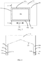
- FIG. 1A shows a schematic top planar view of a work table surface 2 of a three-dimensional printer that uses a particulate build material.
- the work table 2 here forms a curtilage around a build platform 4 that is configured to be step-wise lowered into a build cavity (not shown).
- a particulate dispenser 6 which is adapted to move above and across the work table surface 2 and the build platform 4 in the direction of arrow 8 (see FIG. 1B ), i.e., the particulate layer "deposition direction" or "spread direction", and to selectively deposit a predetermined amount of particulate as it moves along.
- the work table surface 2 is shown prior to the deposition of a first particulate layer and does not have troughs for receiving excess deposited particulate material.
- FIG. ID shows the scene after the image 14 of the first slice of the article that is being built has been imparted to the first particulate layer 10 and the build platform 4 has been indexed downward a distance equal to a layer thickness and the particulate dispenser 6 has been moved back into position to deposit the second particulate layer. Unless an operation has been conducted to remove the excess deposited particulate 12 - and none has been removed in the scene shown in FIG. ID - the excess deposited particulate 12 remains on the surface of the work table 2 and may interfere with the deposition of a second particulate layer and the movement of the particulate dispenser 6 as it deposits the second particulate layer.
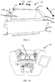
- FIG. 3 is a schematic, perspective, cross-sectional view of a trough 30 .
- the trough 30 has four vertical walls, e.g. vertical wall 32 , a bottom wall 34 , and a top opening 36 .
- the trough 30 also has a perforated partition 38 which contains a plurality of through-holes, e.g. hole 40 .
- the partition 38 divides the space within the trough 30 into a particulate receiving chamber 42 and an evacuation chamber 44 .
- An optional gas inlet 46 is located at one end of the evacuation chamber 44 and a gas outlet 48 is located at the opposite end of the evacuation chamber 44 .
- a nipple 50 is connected to the gas outlet 48 and is adapted to be attached to a vacuum source (not shown).
- the gas inlet 46 is preferably provided with some form of a particulate outflow restrictor 52 which controls the amount of particulate which can flow out of the evacuation chamber 44 through the gas inlet 46 .
- the particulate outflow restrictor 52 shown is in the form of hollow box having one side in communication with the gas inlet 46 and its top side open so as to permit inflow of the ambient atmosphere.
- the streamline arrows 54 show the direction of gas flow when the evacuation chamber 44 is operatively connected to the vacuum source. As indicated by the streamline arrows 54 , the pressure differential imposed by the vacuum source causes ambient gas (e.g.
- Particulates which are in the evacuation chamber 44 or about to enter the evacuation chamber 44 through the holes in the partition 38 may be entrained in the gas flow and exit the evacuation chamber 44 through nipple 50 to be carried off to a collection device, e.g. a cyclone or a screen separator, or otherwise disposed of.
- the partition 38 is shown in FIG. 3 as being flat and horizontally disposed within the space of the trough 30 .
- the partition may be disposed at any desired acute angle from the horizontal.
- FIGS. 4-6 and 11-12 give examples of some of the various configurations the partitions can take.
- FIG. 4 there is shown a schematic perspective view of a partition 60 .
- the top surface 62 of partition 60 is concave across its width. This shape encourages the flow of particulate down into each of the holes 64 located along the length of the partition 60.
- FIG. 5 shows a schematic longitudinal mid-plane cross-sectional view of another partition 70 disposed within a trough 72 .
- the profile of the partition 70 has a semi-parabolic slope from its first end 74 to its second end 76 .
- this profile shapes the evacuation chamber 80 to enhance the acceleration of gas flow and the sweeping away of particulates through the evacuation chamber 80 as indicated by the streamline arrows 82 .
- FIG. 11 shows a schematic perspective view of another partition 150 .
- the partition 150 has a flat bottom wall 152, two sidewalls 154, 156 , and an optional horizontal stiffener 158 .
- the bottom section 152 has a plurality of perforations, e.g. perforation 160 .
- Each of the sidewalls 154, 156 extends upward from the bottom wall 152 at a preselected included angle. Preferably the included angle is in the range of from about 5 to 90 degrees.
- Each of the sidewalls is shown as having an optional extension, e.g., sidewall extension 162 of sidewall 154 , which is adapted to be parallel to the trough vertical wall in which the trough is used (e.g. vertical wall 32 of trough 30 in FIG.
- a sidewall extension allows the sidewall to better seal against the sides of the trough with which the partition is used.
- the horizontal stiffener 158 is attached to the bottom 152 and the perforations extend through the horizontal stiffener 158 .
- a horizontal stabilizer preferably extends horizontally to engage the vertical wall of the trough into which the partition used so as to help position the partition within the trough in which the partition is used.
- one or more of the perforations of one or more of the partitions are adapted to be selectively opened or closed, thus providing the user with the ability to adjust the gas flow path through the partition through selected perforations. Selectively closing selected partition perforations has the effect of controlling the amount particulate flow through the partition.
- the perforation 164 has threads 168 which are sized to cooperate with the threads of the plug 166 to reversibly secure plug 166 (also shown in cross-section) within the perforation 164 (as indicated by arrow) to close off the perforation 164 .
- FIG. 13 shows a schematic perspective view of a strip 170 that is designed to be used in conjunction with the partition shown in FIGS. 11 and 12 .
- the strip 170 has two through-holes 172, 174 which are sized to receive screws (not shown) which extend through through-holes 172, 174 and thread into threaded perforations (e.g. perforation 164 shown in FIG. 11 ) of partition 150 to secure the strip 170 to the partition 150 .
- the strip 170 is long enough to close five perforations of the partition 150 including the two perforations which are closed off by the screws which secure the strip 170 to the partition 150 .
- the selection of the number, size, shape, and locations of the holes in the partition of a trough may be made depending on several factors. Two closely related factors are the size distribution range and the shapes of the particulates that are to be used during the three-dimensional printing operation. It is preferable that the holes be sized and shaped to allow passage of all shapes and sizes within the size distribution range without the occurrence of particulate bridging of the holes. Additional factors are the partition's profile and its angle of disposition. It is preferred that the number and distribution of holes be chosen to avoid the accumulation of particulates on the portion or portions of the partition to which the partition's profile and/or angular disposition direct greater numbers of particulates.
- gas flow rate through the evacuation chamber and whether or not a gas inlet (e.g., gas inlet 46 of FIG. 3 ) has been provided to the evacuation chamber. It is desirable to size, shape, and distribute the holes to promote particulate entrainment in the vacuum-induced gas flow through the holes. It is to be understood that in embodiments wherein the optional gas inlet of the evacuation chamber is omitted, there is no need for a particulate outflow restrictor, e.g. the particulate outflow restrictor 52 shown in FIG. 3 . Also, in that case, all gas inflow into the evacuation chamber is through the holes in the partition.
- a gas inlet e.g., gas inlet 46 of FIG. 3
- the partition may be removed from its trough and replaced with a substitute partition.
- the substitute partition may have holes which are different in number, size, shape, and/or locations from the holes of the original partition and/or have a configuration that is different from that of the original partition and/or be adapted to have an angle of disposition which is different from that of the original partition. It is preferable to seal the partition against the sides of the trough so that the only passageways for particulate from the particulate receiving chamber to the evacuation chamber is through the holes in the partition.
- the present invention includes three-dimensional printing apparatuses having of one or more of the troughs which are adapted to directly and/or indirectly collect the excess deposited particulates appurtenant to the deposition of particulate layers during the three-dimensional printing operation.
- the trough or troughs are positioned adjacent to the build platform so as to directly receive the excess deposited particulate, e.g. in the relative locations of conventional troughs 16a-16d shown in FIG. 2 .
- one or more inventive troughs i.e. troughs having some version of the evacuation chamber system described above
- at least one of the conventional troughs conveys some or all of the excess deposited particulate into one or more of the inventive troughs.
- FIG. 7 shows such an embodiment.
- FIG. 8 presents a schematic cutaway side view taken across cutting plane 8-8 of FIG. 7 .
- the conventional trough 110a is positioned between troughs 108a, 108b .
- the troughs 108a, 108b have, respectively, particulate receiving chambers 112a, 112b , partition plates 114a, 114b (having through holes such as holes 116a, 116b ), and evacuation chambers 118a, 118b .
- the conventional trough 110a has a peaked bottom 119 which slopes so as to direct excess deposited particulate toward the particulate receiving chambers 112a, 112b of the troughs 108a, 108b .
- the troughs are built directly into the three-dimensional printing apparatus so that they are a permanent part of the apparatus.
- FIG. 7 illustrates one such embodiment.
- one or more of the troughs are disposed in a removable unit which is adapted to be inserted into the three-dimensional printing apparatus during a particular three-dimensional printing operation and then removed thereafter.
- the removable unit also includes a build box having walls designed to laterally confine the particulate bed and a build platform which is adapted to be raised or lowered.
- FIG. 9 is a perspective view of a build box 120 of such an embodiment.
- the build box 120 also has two conventional troughs 130a, 130b and two further troughs 132a, 132b.
- the build box 120 also has nipple 134 which is adapted to connect the trough 132b to a vacuum source and a particulate outflow restrictor 136 which has an open top 138 and is in communication with the gas inlet (not shown) for inventive trough 132b.
- the build box 120 also includes a corresponding nipple and particle outflow restrictor with a gas inlet for trough 132a.
- FIG. 10 shows a schematic perspective view of a three-dimensional printer 140 into which the build box 120 has been inserted.
- the present invention includes within its scope three-dimensional printers that have build cavities that have one or more non-planar walls for laterally confining the build bed.
- one or more of the walls may be curved.
- the build cavity may have a circular cross-section circumscribed by a continuously curved wall.
- Such non-planar walled build cavities may be either a permanent part of the three-dimensional printing apparatus of part of a removable build box.
- the troughs of embodiments may have curved shapes. Such curved shaped troughs are preferred for use adjacent to a curved build cavity wall. Such curved troughs may be either a permanent part of the three-dimensional printing apparatus or removable, e.g., as part of a build box. Troughs having a curved shape may be either the troughs having an evacuation chamber or troughs not having an evacuation chamber.
- the particulates which are removed from a trough's evacuation chamber are subsequently collected in a collection device, e.g. a cyclone, screen separator, electrostatic precipitator, scrubber, etc.
- a collection device e.g. a cyclone, screen separator, electrostatic precipitator, scrubber, etc.
- the collection device is chosen so as to permit reuse of the collected particulate in the three-dimensional printing process with little or no subsequent conditioning operation.
- the collection device may be an integral part of the three-dimensional printer apparatus, preferably the collection device is either removably attached to the three-dimensional printer apparatus or is separate from the three-dimensional printer apparatus. These latter two configurations make it easier to avoid cross-contamination when the three-dimensional printer apparatus is first used for one type of particulate and then another type.
Landscapes
- Chemical & Material Sciences (AREA)
- Engineering & Computer Science (AREA)
- Materials Engineering (AREA)
- Manufacturing & Machinery (AREA)
- Physics & Mathematics (AREA)
- Optics & Photonics (AREA)
- Mechanical Engineering (AREA)
- Life Sciences & Earth Sciences (AREA)
- Sustainable Development (AREA)
Claims (8)
- Eine 3D-Druckvorrichtung (140), die zum Bauen von Artikeln aus einem Partikelmaterial angepasst ist, aufweisend einen Arbeitstisch (100) und eine überschüssiges Partikelmaterial aufnehmende Wanne/Rinne (30), die eine offene Oberseite (36) hat und innerhalb des Arbeitstisches (100) angeordnet ist, wobei die Wanne/Rinne aufweist eine Kammer, die durch eine Mehrzahl von Seiten (32), einen Boden (34) und die offene Oberseite (36) definiert ist, eine Trennwand (70), die ein semi-hyperbolisches Längsprofil hat, einen Gaseinlass (46) und einen Gasauslass (48), wobei die Trennwand (70) in Längsrichtung innerhalb der Kammer proximal zu dem Boden (34) angeordnet ist, wodurch sie die Kammer in eine obere Kammer (42) und eine untere Kammer (44) aufteilt, der Gasauslass (48) an einem ersten Ende der unteren Kammer (44) angeordnet ist, der Gaseinlass (46) an einem zweiten Ende der unteren Kammer (44) angeordnet ist, die Trennwand (70) eine Mehrzahl von Durchgangslöchern (40) hat, die angepasst sind, um einen Gasstrom und einen Partikelmaterialstrom aus der oberen Kammer (42) in die untere Kammer (44) zuzulassen, und der Gasauslass (48) angepasst ist, um mit einer Vakuumquelle verbunden zu sein.
- Die 3D-Druckvorrichtung (140) gemäß Anspruch 1, ferner aufweisend einen Stopfen (166), der angepasst ist, um lösbar an der Trennwand (70) angebracht zu sein, um eines der Durchgangslöcher (40) der Mehrzahl von Durchgangslöchern (40) wahlweise zu verschließen.
- Die 3D-Druckvorrichtung (140) gemäß Anspruch 1, ferner aufweisend einen Streifen (170), der angepasst ist, um lösbar an der Trennwand (70) angebracht zu sein, um mindestens zwei Durchgangslöcher (40) der Mehrzahl von Durchgangslöchern (40) wahlweise zu verschließen.
- Die 3D-Druckvorrichtung (140) gemäß Anspruch 1, ferner aufweisend einen Partikelmaterial-Ausström-Begrenzer (136), wobei der Partikelmaterial-Ausström-Begrenzer (146) mit dem Gaseinlass (46) und der unteren Kammer (44) in Fluidverbindung ist.
- Eine Baubox (120), die angepasst ist, um entnehmbar durch eine 3D-Druckvorrichtung (30) aufnehmbar zu sein, die angepasst ist, um aus Partikelmaterial Artikel zu bauen, wobei die Baubox (120) aufweist einen Bau-Hohlraum (126) und eine überschüssiges Partikelmaterial aufnehmende Wanne/Rinne (132a), die benachbart zu dem Bau-Hohlraum (126) angeordnet ist, wobei die Wanne/Rinne (132a) aufweist eine Kammer, die durch eine Mehrzahl von Seiten (32), einen Boden (34) und die offene Oberseite (36) definiert ist, eine Trennwand (70), die ein semi-hyperbolisches Längsprofil hat, einen Gaseinlass (46) und einen Gasauslass (48), wobei die Trennwand (70) in Längsrichtung innerhalb der Kammer proximal zum Boden (34) angeordnet ist, wodurch die Kammer in eine obere Kammer (42) und eine untere Kammer (44) aufgeteilt wird, der Gasauslass (48) an einem ersten Ende der unteren Kammer (44) angeordnet ist, der Gaseinlass (46) an einem zweiten Ende der unteren Kammer (44) angeordnet ist, die Trennwand (70) eine Mehrzahl von Durchgangslöchern (40) aufweist, die angepasst sind, um einen Gasstrom und einen Partikelmaterialstrom aus der oberen Kammer (42) in die untere Kammer (44) zuzulassen, und der Gasauslass (48) angepasst ist, um mit einer Vakuumquelle verbunden zu sein.
- Die Baubox (120) gemäß Anspruch 5, ferner aufweisend einen Stopfen (166), der angepasst ist, um lösbar an der Trennwand (70) angebracht zu sein, um eines der Durchgangslöcher (40) der Mehrzahl von Durchgangslöchern (40) wahlweise zu verschließen.
- Die Baubox (120) gemäß Anspruch 5, ferner aufweisend einen Streifen (170), der angepasst ist, um lösbar an der Trennwand (70) angebracht zu sein, um mindestens zwei Durchgangslöcher (40) der Mehrzahl von Durchgangslöchern (40) wahlweise zu verschließen.
- Die Baubox (120) gemäß Anspruch 5, ferner aufweisend einen Partikelmaterial-Ausström-Begrenzer (136), wobei der Partikelmaterial-Ausström-Begrenzer (146) in Fluidverbindung mit dem Gaseinlass (46) und der unteren Kammer (44) ist.
Applications Claiming Priority (3)
| Application Number | Priority Date | Filing Date | Title |
|---|---|---|---|
| US201461990439P | 2014-05-08 | 2014-05-08 | |
| US201462013584P | 2014-06-18 | 2014-06-18 | |
| PCT/US2015/029578 WO2015171841A1 (en) | 2014-05-08 | 2015-05-07 | Three-dimensional printing excess deposited particulate handling |
Publications (3)
| Publication Number | Publication Date |
|---|---|
| EP3140123A1 EP3140123A1 (de) | 2017-03-15 |
| EP3140123A4 EP3140123A4 (de) | 2018-02-21 |
| EP3140123B1 true EP3140123B1 (de) | 2018-09-19 |
Family
ID=54392981
Family Applications (1)
| Application Number | Title | Priority Date | Filing Date |
|---|---|---|---|
| EP15788613.6A Active EP3140123B1 (de) | 2014-05-08 | 2015-05-07 | Handhabung von abgeschiedenem überschuss beim dreidimensionalen drucken |
Country Status (3)
| Country | Link |
|---|---|
| US (1) | US10144207B2 (de) |
| EP (1) | EP3140123B1 (de) |
| WO (1) | WO2015171841A1 (de) |
Families Citing this family (15)
| Publication number | Priority date | Publication date | Assignee | Title |
|---|---|---|---|---|
| US10583606B2 (en) * | 2016-02-11 | 2020-03-10 | General Electric Company | Method and supports with powder removal ports for additive manufacturing |
| CN105643941A (zh) * | 2016-03-07 | 2016-06-08 | 宁夏共享模具有限公司 | 一种3d打印设备的铺料装置 |
| KR102207400B1 (ko) * | 2016-07-22 | 2021-01-26 | 휴렛-팩커드 디벨롭먼트 컴퍼니, 엘.피. | 분말 빌드 재료 취급 |
| CN110612191A (zh) * | 2017-04-21 | 2019-12-24 | 惠普发展公司,有限责任合伙企业 | 三维打印机 |
| US20180345370A1 (en) * | 2017-05-31 | 2018-12-06 | General Electric Company | Apparatus with large, stationary raw material supply mechanism and method for continuous additive manufacturing |
| WO2019067545A1 (en) * | 2017-09-28 | 2019-04-04 | 3D Systems, Inc. | HIGH CAPACITY APPARATUS FOR THE MANUFACTURE OF LAMINATES FROM POWDER MATERIALS |
| US11590691B2 (en) * | 2017-11-02 | 2023-02-28 | General Electric Company | Plate-based additive manufacturing apparatus and method |
| WO2019094367A1 (en) * | 2017-11-10 | 2019-05-16 | General Electric Company | Powder reclamation and cleaning system for an additive manufacturing machine |
| US11117329B2 (en) | 2018-06-26 | 2021-09-14 | General Electric Company | Additively manufactured build assemblies having reduced distortion and residual stress |
| US11020763B2 (en) | 2018-08-21 | 2021-06-01 | General Electric Company | Spacer flow guide for partitioning build chamber of an additive manufacturing system |
| US11371788B2 (en) | 2018-09-10 | 2022-06-28 | General Electric Company | Heat exchangers with a particulate flushing manifold and systems and methods of flushing particulates from a heat exchanger |
| US11440097B2 (en) | 2019-02-12 | 2022-09-13 | General Electric Company | Methods for additively manufacturing components using lattice support structures |
| US11504879B2 (en) | 2020-04-17 | 2022-11-22 | Beehive Industries, LLC | Powder spreading apparatus and system |
| US11534972B2 (en) * | 2020-08-31 | 2022-12-27 | GM Global Technology Operations LLC | Post-build quick powder removal system for powder bed fusion additive manufacturing |
| CN116330651B (zh) * | 2023-03-31 | 2023-10-27 | 苏州研拓自动化科技有限公司 | 一种基于隔离碗的高分子材料3d打印机铺粉机构 |
Family Cites Families (11)
| Publication number | Priority date | Publication date | Assignee | Title |
|---|---|---|---|---|
| US419751A (en) * | 1890-01-21 | Rotary sifter | ||
| US3445973A (en) * | 1967-02-01 | 1969-05-27 | Robert E Stone | Removable cover for drain fixture |
| US6007318A (en) * | 1996-12-20 | 1999-12-28 | Z Corporation | Method and apparatus for prototyping a three-dimensional object |
| US20060214335A1 (en) * | 2005-03-09 | 2006-09-28 | 3D Systems, Inc. | Laser sintering powder recycle system |
| KR20080086428A (ko) * | 2005-09-20 | 2008-09-25 | 피티에스 소프트웨어 비브이 | 3차원 아티클의 구축 장치 및 3차원 아티클의 구축 방법 |
| US7971991B2 (en) * | 2006-05-26 | 2011-07-05 | Z Corporation | Apparatus and methods for handling materials in a 3-D printer |
| WO2008103985A2 (en) * | 2007-02-23 | 2008-08-28 | The Exone Company, Llc | Replaceable build box for three dimensional printer |
| CN102380264B (zh) * | 2010-08-31 | 2014-04-09 | 研能科技股份有限公司 | 自动粉末回收装置 |
| US8883064B2 (en) * | 2011-06-02 | 2014-11-11 | A. Raymond & Cie | Method of making printed fastener |
| US8840230B2 (en) * | 2012-06-04 | 2014-09-23 | Xerox Corporation | Ink waste tray configured with one way filter |
| US8888480B2 (en) * | 2012-09-05 | 2014-11-18 | Aprecia Pharmaceuticals Company | Three-dimensional printing system and equipment assembly |
-
2015
- 2015-05-07 WO PCT/US2015/029578 patent/WO2015171841A1/en active Application Filing
- 2015-05-07 US US15/319,288 patent/US10144207B2/en not_active Expired - Fee Related
- 2015-05-07 EP EP15788613.6A patent/EP3140123B1/de active Active
Non-Patent Citations (1)
| Title |
|---|
| None * |
Also Published As
| Publication number | Publication date |
|---|---|
| EP3140123A4 (de) | 2018-02-21 |
| US10144207B2 (en) | 2018-12-04 |
| WO2015171841A1 (en) | 2015-11-12 |
| US20170120536A1 (en) | 2017-05-04 |
| EP3140123A1 (de) | 2017-03-15 |
Similar Documents
| Publication | Publication Date | Title |
|---|---|---|
| EP3140123B1 (de) | Handhabung von abgeschiedenem überschuss beim dreidimensionalen drucken | |
| EP3463817B1 (de) | Dreidimensionaler pulverschicht-drucker, der einen nachbeschichter umfasst | |
| US11097480B2 (en) | Post-processing in 3D printing systems using a separate material management apparatus | |
| US7435072B2 (en) | Methods and systems for producing an object through solid freeform fabrication | |
| JP7053591B2 (ja) | 粒子を操作するためのデバイスおよび方法 | |
| JP6905528B2 (ja) | トレイ及び噴射器を有する粉末分配システムを備えた付加製造機 | |
| CN105848751A (zh) | 用于油漆微粒的清洁系统 | |
| US8869562B2 (en) | Glass forming apparatus | |
| DE102007005306A1 (de) | Pulverzufuhrvorrichtung von einer Pulversprühbeschichtungsanlage | |
| US9700912B2 (en) | Fluid transport media | |
| US20130206649A1 (en) | Screening device and method of screening | |
| US20140238240A1 (en) | Downflow dust collectors having dirty air channels | |
| WO2020053567A1 (en) | Powder bed fusion apparatus and methods | |
| US20220274169A1 (en) | Powder removal floating structures | |
| CN114190085A (zh) | 用于在增材制造中沉积粒状材料的设备和方法 | |
| US20220371273A1 (en) | Additive manufacturing tray | |
| JP2017530703A (ja) | ロッド状の消費財をパック用装置に供給する方法 | |
| WO2015008348A1 (ja) | 粉粒体の定量供給装置及びその定量供給方法 | |
| US9254674B2 (en) | Reservoir having particle trapping features | |
| CN111836685B (zh) | 气体喷出喷嘴及炉、以及加工膜的制造方法 | |
| US11565471B2 (en) | Three-dimensional printing with diffuser plate | |
| KR102324220B1 (ko) | 칩 이송장치 | |
| WO2023156845A1 (en) | Apparatus for dry granular mixtures separation | |
| WO2021211088A1 (en) | Additively manufacturing a first 3d object at least partially containing a second 3d object | |
| WO2013145124A1 (ja) | 固液分離装置、及びこれを適用した液処理システム |
Legal Events
| Date | Code | Title | Description |
|---|---|---|---|
| STAA | Information on the status of an ep patent application or granted ep patent |
Free format text: STATUS: THE INTERNATIONAL PUBLICATION HAS BEEN MADE |
|
| PUAI | Public reference made under article 153(3) epc to a published international application that has entered the european phase |
Free format text: ORIGINAL CODE: 0009012 |
|
| STAA | Information on the status of an ep patent application or granted ep patent |
Free format text: STATUS: REQUEST FOR EXAMINATION WAS MADE |
|
| 17P | Request for examination filed |
Effective date: 20161222 |
|
| AK | Designated contracting states |
Kind code of ref document: A1 Designated state(s): AL AT BE BG CH CY CZ DE DK EE ES FI FR GB GR HR HU IE IS IT LI LT LU LV MC MK MT NL NO PL PT RO RS SE SI SK SM TR |
|
| AX | Request for extension of the european patent |
Extension state: BA ME |
|
| RIN1 | Information on inventor provided before grant (corrected) |
Inventor name: LIZZI, THOMAS Inventor name: BRUNERMER, DANIEL, T. Inventor name: DUGAN, ANTHONY, S. |
|
| DAV | Request for validation of the european patent (deleted) | ||
| DAX | Request for extension of the european patent (deleted) | ||
| A4 | Supplementary search report drawn up and despatched |
Effective date: 20180124 |
|
| RIC1 | Information provided on ipc code assigned before grant |
Ipc: B29C 64/357 20170101ALI20180118BHEP Ipc: B41J 2/17 20060101ALI20180118BHEP Ipc: B41J 2/175 20060101AFI20180118BHEP Ipc: B29C 64/165 20170101ALI20180118BHEP Ipc: B33Y 10/00 20150101ALI20180118BHEP Ipc: B29C 64/153 20170101ALI20180118BHEP Ipc: B29K 105/00 20060101ALI20180118BHEP Ipc: B33Y 40/00 20150101ALI20180118BHEP Ipc: B41J 29/02 20060101ALI20180118BHEP Ipc: B33Y 30/00 20150101ALI20180118BHEP |
|
| GRAP | Despatch of communication of intention to grant a patent |
Free format text: ORIGINAL CODE: EPIDOSNIGR1 |
|
| STAA | Information on the status of an ep patent application or granted ep patent |
Free format text: STATUS: GRANT OF PATENT IS INTENDED |
|
| RIC1 | Information provided on ipc code assigned before grant |
Ipc: B29C 64/165 20170101ALI20180309BHEP Ipc: B29C 64/153 20170101ALI20180309BHEP Ipc: B41J 2/17 20060101ALI20180309BHEP Ipc: B33Y 40/00 20150101ALI20180309BHEP Ipc: B41J 2/175 20060101AFI20180309BHEP Ipc: B33Y 10/00 20150101ALI20180309BHEP Ipc: B33Y 30/00 20150101ALI20180309BHEP Ipc: B29K 105/00 20060101ALI20180309BHEP Ipc: B29C 64/357 20170101ALI20180309BHEP Ipc: B41J 29/02 20060101ALI20180309BHEP |
|
| INTG | Intention to grant announced |
Effective date: 20180412 |
|
| GRAS | Grant fee paid |
Free format text: ORIGINAL CODE: EPIDOSNIGR3 |
|
| GRAA | (expected) grant |
Free format text: ORIGINAL CODE: 0009210 |
|
| STAA | Information on the status of an ep patent application or granted ep patent |
Free format text: STATUS: THE PATENT HAS BEEN GRANTED |
|
| RIN1 | Information on inventor provided before grant (corrected) |
Inventor name: LIZZI, THOMAS Inventor name: DUGAN, ANTHONY, S. Inventor name: BRUNERMER, DANIEL, T. |
|
| AK | Designated contracting states |
Kind code of ref document: B1 Designated state(s): AL AT BE BG CH CY CZ DE DK EE ES FI FR GB GR HR HU IE IS IT LI LT LU LV MC MK MT NL NO PL PT RO RS SE SI SK SM TR |
|
| REG | Reference to a national code |
Ref country code: GB Ref legal event code: FG4D |
|
| REG | Reference to a national code |
Ref country code: CH Ref legal event code: EP |
|
| REG | Reference to a national code |
Ref country code: AT Ref legal event code: REF Ref document number: 1042790 Country of ref document: AT Kind code of ref document: T Effective date: 20181015 |
|
| REG | Reference to a national code |
Ref country code: IE Ref legal event code: FG4D |
|
| REG | Reference to a national code |
Ref country code: DE Ref legal event code: R096 Ref document number: 602015016729 Country of ref document: DE |
|
| REG | Reference to a national code |
Ref country code: NL Ref legal event code: FP |
|
| REG | Reference to a national code |
Ref country code: SE Ref legal event code: TRGR |
|
| PG25 | Lapsed in a contracting state [announced via postgrant information from national office to epo] |
Ref country code: FI Free format text: LAPSE BECAUSE OF FAILURE TO SUBMIT A TRANSLATION OF THE DESCRIPTION OR TO PAY THE FEE WITHIN THE PRESCRIBED TIME-LIMIT Effective date: 20180919 Ref country code: LT Free format text: LAPSE BECAUSE OF FAILURE TO SUBMIT A TRANSLATION OF THE DESCRIPTION OR TO PAY THE FEE WITHIN THE PRESCRIBED TIME-LIMIT Effective date: 20180919 Ref country code: GR Free format text: LAPSE BECAUSE OF FAILURE TO SUBMIT A TRANSLATION OF THE DESCRIPTION OR TO PAY THE FEE WITHIN THE PRESCRIBED TIME-LIMIT Effective date: 20181220 Ref country code: RS Free format text: LAPSE BECAUSE OF FAILURE TO SUBMIT A TRANSLATION OF THE DESCRIPTION OR TO PAY THE FEE WITHIN THE PRESCRIBED TIME-LIMIT Effective date: 20180919 Ref country code: NO Free format text: LAPSE BECAUSE OF FAILURE TO SUBMIT A TRANSLATION OF THE DESCRIPTION OR TO PAY THE FEE WITHIN THE PRESCRIBED TIME-LIMIT Effective date: 20181219 Ref country code: BG Free format text: LAPSE BECAUSE OF FAILURE TO SUBMIT A TRANSLATION OF THE DESCRIPTION OR TO PAY THE FEE WITHIN THE PRESCRIBED TIME-LIMIT Effective date: 20181219 |
|
| REG | Reference to a national code |
Ref country code: LT Ref legal event code: MG4D |
|
| PG25 | Lapsed in a contracting state [announced via postgrant information from national office to epo] |
Ref country code: AL Free format text: LAPSE BECAUSE OF FAILURE TO SUBMIT A TRANSLATION OF THE DESCRIPTION OR TO PAY THE FEE WITHIN THE PRESCRIBED TIME-LIMIT Effective date: 20180919 Ref country code: LV Free format text: LAPSE BECAUSE OF FAILURE TO SUBMIT A TRANSLATION OF THE DESCRIPTION OR TO PAY THE FEE WITHIN THE PRESCRIBED TIME-LIMIT Effective date: 20180919 Ref country code: HR Free format text: LAPSE BECAUSE OF FAILURE TO SUBMIT A TRANSLATION OF THE DESCRIPTION OR TO PAY THE FEE WITHIN THE PRESCRIBED TIME-LIMIT Effective date: 20180919 |
|
| REG | Reference to a national code |
Ref country code: AT Ref legal event code: MK05 Ref document number: 1042790 Country of ref document: AT Kind code of ref document: T Effective date: 20180919 |
|
| PG25 | Lapsed in a contracting state [announced via postgrant information from national office to epo] |
Ref country code: PL Free format text: LAPSE BECAUSE OF FAILURE TO SUBMIT A TRANSLATION OF THE DESCRIPTION OR TO PAY THE FEE WITHIN THE PRESCRIBED TIME-LIMIT Effective date: 20180919 Ref country code: EE Free format text: LAPSE BECAUSE OF FAILURE TO SUBMIT A TRANSLATION OF THE DESCRIPTION OR TO PAY THE FEE WITHIN THE PRESCRIBED TIME-LIMIT Effective date: 20180919 Ref country code: AT Free format text: LAPSE BECAUSE OF FAILURE TO SUBMIT A TRANSLATION OF THE DESCRIPTION OR TO PAY THE FEE WITHIN THE PRESCRIBED TIME-LIMIT Effective date: 20180919 Ref country code: ES Free format text: LAPSE BECAUSE OF FAILURE TO SUBMIT A TRANSLATION OF THE DESCRIPTION OR TO PAY THE FEE WITHIN THE PRESCRIBED TIME-LIMIT Effective date: 20180919 Ref country code: RO Free format text: LAPSE BECAUSE OF FAILURE TO SUBMIT A TRANSLATION OF THE DESCRIPTION OR TO PAY THE FEE WITHIN THE PRESCRIBED TIME-LIMIT Effective date: 20180919 Ref country code: CZ Free format text: LAPSE BECAUSE OF FAILURE TO SUBMIT A TRANSLATION OF THE DESCRIPTION OR TO PAY THE FEE WITHIN THE PRESCRIBED TIME-LIMIT Effective date: 20180919 Ref country code: IT Free format text: LAPSE BECAUSE OF FAILURE TO SUBMIT A TRANSLATION OF THE DESCRIPTION OR TO PAY THE FEE WITHIN THE PRESCRIBED TIME-LIMIT Effective date: 20180919 Ref country code: IS Free format text: LAPSE BECAUSE OF FAILURE TO SUBMIT A TRANSLATION OF THE DESCRIPTION OR TO PAY THE FEE WITHIN THE PRESCRIBED TIME-LIMIT Effective date: 20190119 |
|
| PG25 | Lapsed in a contracting state [announced via postgrant information from national office to epo] |
Ref country code: PT Free format text: LAPSE BECAUSE OF FAILURE TO SUBMIT A TRANSLATION OF THE DESCRIPTION OR TO PAY THE FEE WITHIN THE PRESCRIBED TIME-LIMIT Effective date: 20190119 Ref country code: SM Free format text: LAPSE BECAUSE OF FAILURE TO SUBMIT A TRANSLATION OF THE DESCRIPTION OR TO PAY THE FEE WITHIN THE PRESCRIBED TIME-LIMIT Effective date: 20180919 Ref country code: SK Free format text: LAPSE BECAUSE OF FAILURE TO SUBMIT A TRANSLATION OF THE DESCRIPTION OR TO PAY THE FEE WITHIN THE PRESCRIBED TIME-LIMIT Effective date: 20180919 |
|
| REG | Reference to a national code |
Ref country code: DE Ref legal event code: R097 Ref document number: 602015016729 Country of ref document: DE |
|
| PLBE | No opposition filed within time limit |
Free format text: ORIGINAL CODE: 0009261 |
|
| STAA | Information on the status of an ep patent application or granted ep patent |
Free format text: STATUS: NO OPPOSITION FILED WITHIN TIME LIMIT |
|
| PG25 | Lapsed in a contracting state [announced via postgrant information from national office to epo] |
Ref country code: DK Free format text: LAPSE BECAUSE OF FAILURE TO SUBMIT A TRANSLATION OF THE DESCRIPTION OR TO PAY THE FEE WITHIN THE PRESCRIBED TIME-LIMIT Effective date: 20180919 |
|
| 26N | No opposition filed |
Effective date: 20190620 |
|
| PG25 | Lapsed in a contracting state [announced via postgrant information from national office to epo] |
Ref country code: SI Free format text: LAPSE BECAUSE OF FAILURE TO SUBMIT A TRANSLATION OF THE DESCRIPTION OR TO PAY THE FEE WITHIN THE PRESCRIBED TIME-LIMIT Effective date: 20180919 |
|
| REG | Reference to a national code |
Ref country code: CH Ref legal event code: PL |
|
| PG25 | Lapsed in a contracting state [announced via postgrant information from national office to epo] |
Ref country code: LI Free format text: LAPSE BECAUSE OF NON-PAYMENT OF DUE FEES Effective date: 20190531 Ref country code: CH Free format text: LAPSE BECAUSE OF NON-PAYMENT OF DUE FEES Effective date: 20190531 Ref country code: MC Free format text: LAPSE BECAUSE OF FAILURE TO SUBMIT A TRANSLATION OF THE DESCRIPTION OR TO PAY THE FEE WITHIN THE PRESCRIBED TIME-LIMIT Effective date: 20180919 |
|
| REG | Reference to a national code |
Ref country code: BE Ref legal event code: MM Effective date: 20190531 |
|
| PG25 | Lapsed in a contracting state [announced via postgrant information from national office to epo] |
Ref country code: LU Free format text: LAPSE BECAUSE OF NON-PAYMENT OF DUE FEES Effective date: 20190507 |
|
| PG25 | Lapsed in a contracting state [announced via postgrant information from national office to epo] |
Ref country code: TR Free format text: LAPSE BECAUSE OF FAILURE TO SUBMIT A TRANSLATION OF THE DESCRIPTION OR TO PAY THE FEE WITHIN THE PRESCRIBED TIME-LIMIT Effective date: 20180919 |
|
| PG25 | Lapsed in a contracting state [announced via postgrant information from national office to epo] |
Ref country code: IE Free format text: LAPSE BECAUSE OF NON-PAYMENT OF DUE FEES Effective date: 20190507 |
|
| PG25 | Lapsed in a contracting state [announced via postgrant information from national office to epo] |
Ref country code: BE Free format text: LAPSE BECAUSE OF NON-PAYMENT OF DUE FEES Effective date: 20190531 |
|
| PG25 | Lapsed in a contracting state [announced via postgrant information from national office to epo] |
Ref country code: CY Free format text: LAPSE BECAUSE OF FAILURE TO SUBMIT A TRANSLATION OF THE DESCRIPTION OR TO PAY THE FEE WITHIN THE PRESCRIBED TIME-LIMIT Effective date: 20180919 |
|
| PG25 | Lapsed in a contracting state [announced via postgrant information from national office to epo] |
Ref country code: HU Free format text: LAPSE BECAUSE OF FAILURE TO SUBMIT A TRANSLATION OF THE DESCRIPTION OR TO PAY THE FEE WITHIN THE PRESCRIBED TIME-LIMIT; INVALID AB INITIO Effective date: 20150507 Ref country code: MT Free format text: LAPSE BECAUSE OF FAILURE TO SUBMIT A TRANSLATION OF THE DESCRIPTION OR TO PAY THE FEE WITHIN THE PRESCRIBED TIME-LIMIT Effective date: 20180919 |
|
| PG25 | Lapsed in a contracting state [announced via postgrant information from national office to epo] |
Ref country code: MK Free format text: LAPSE BECAUSE OF FAILURE TO SUBMIT A TRANSLATION OF THE DESCRIPTION OR TO PAY THE FEE WITHIN THE PRESCRIBED TIME-LIMIT Effective date: 20180919 |
|
| P01 | Opt-out of the competence of the unified patent court (upc) registered |
Effective date: 20230605 |
|
| PGFP | Annual fee paid to national office [announced via postgrant information from national office to epo] |
Ref country code: NL Payment date: 20230519 Year of fee payment: 9 Ref country code: FR Payment date: 20230517 Year of fee payment: 9 Ref country code: DE Payment date: 20230421 Year of fee payment: 9 |
|
| PGFP | Annual fee paid to national office [announced via postgrant information from national office to epo] |
Ref country code: SE Payment date: 20230519 Year of fee payment: 9 |
|
| PGFP | Annual fee paid to national office [announced via postgrant information from national office to epo] |
Ref country code: GB Payment date: 20230522 Year of fee payment: 9 |