EP3140077B1 - Machine tool system and method for operating a machine tool system - Google Patents
Machine tool system and method for operating a machine tool system Download PDFInfo
- Publication number
- EP3140077B1 EP3140077B1 EP15723662.1A EP15723662A EP3140077B1 EP 3140077 B1 EP3140077 B1 EP 3140077B1 EP 15723662 A EP15723662 A EP 15723662A EP 3140077 B1 EP3140077 B1 EP 3140077B1
- Authority
- EP
- European Patent Office
- Prior art keywords
- workpiece
- adapter
- machine tool
- workpieces
- gripping device
- Prior art date
- Legal status (The legal status is an assumption and is not a legal conclusion. Google has not performed a legal analysis and makes no representation as to the accuracy of the status listed.)
- Active
Links
- 238000000034 method Methods 0.000 title claims description 18
- 238000003754 machining Methods 0.000 claims description 31
- 230000005484 gravity Effects 0.000 claims description 16
- 238000003860 storage Methods 0.000 claims description 11
- 238000004140 cleaning Methods 0.000 claims description 10
- 238000012360 testing method Methods 0.000 claims description 9
- 238000012546 transfer Methods 0.000 claims description 9
- 238000012545 processing Methods 0.000 description 14
- 230000002349 favourable effect Effects 0.000 description 8
- 238000004049 embossing Methods 0.000 description 5
- 238000013461 design Methods 0.000 description 4
- 238000006243 chemical reaction Methods 0.000 description 3
- 230000007547 defect Effects 0.000 description 2
- 238000006073 displacement reaction Methods 0.000 description 2
- 239000010720 hydraulic oil Substances 0.000 description 2
- 238000004891 communication Methods 0.000 description 1
- 238000004519 manufacturing process Methods 0.000 description 1
- 238000003801 milling Methods 0.000 description 1
- 230000002040 relaxant effect Effects 0.000 description 1
- 238000011144 upstream manufacturing Methods 0.000 description 1
Images


Classifications
-
- B—PERFORMING OPERATIONS; TRANSPORTING
- B23—MACHINE TOOLS; METAL-WORKING NOT OTHERWISE PROVIDED FOR
- B23Q—DETAILS, COMPONENTS, OR ACCESSORIES FOR MACHINE TOOLS, e.g. ARRANGEMENTS FOR COPYING OR CONTROLLING; MACHINE TOOLS IN GENERAL CHARACTERISED BY THE CONSTRUCTION OF PARTICULAR DETAILS OR COMPONENTS; COMBINATIONS OR ASSOCIATIONS OF METAL-WORKING MACHINES, NOT DIRECTED TO A PARTICULAR RESULT
- B23Q7/00—Arrangements for handling work specially combined with or arranged in, or specially adapted for use in connection with, machine tools, e.g. for conveying, loading, positioning, discharging, sorting
- B23Q7/04—Arrangements for handling work specially combined with or arranged in, or specially adapted for use in connection with, machine tools, e.g. for conveying, loading, positioning, discharging, sorting by means of grippers
- B23Q7/048—Multiple gripper units
-
- B—PERFORMING OPERATIONS; TRANSPORTING
- B23—MACHINE TOOLS; METAL-WORKING NOT OTHERWISE PROVIDED FOR
- B23P—METAL-WORKING NOT OTHERWISE PROVIDED FOR; COMBINED OPERATIONS; UNIVERSAL MACHINE TOOLS
- B23P23/00—Machines or arrangements of machines for performing specified combinations of different metal-working operations not covered by a single other subclass
- B23P23/06—Metal-working plant comprising a number of associated machines or apparatus
-
- B—PERFORMING OPERATIONS; TRANSPORTING
- B23—MACHINE TOOLS; METAL-WORKING NOT OTHERWISE PROVIDED FOR
- B23Q—DETAILS, COMPONENTS, OR ACCESSORIES FOR MACHINE TOOLS, e.g. ARRANGEMENTS FOR COPYING OR CONTROLLING; MACHINE TOOLS IN GENERAL CHARACTERISED BY THE CONSTRUCTION OF PARTICULAR DETAILS OR COMPONENTS; COMBINATIONS OR ASSOCIATIONS OF METAL-WORKING MACHINES, NOT DIRECTED TO A PARTICULAR RESULT
- B23Q16/00—Equipment for precise positioning of tool or work into particular locations not otherwise provided for
-
- B—PERFORMING OPERATIONS; TRANSPORTING
- B23—MACHINE TOOLS; METAL-WORKING NOT OTHERWISE PROVIDED FOR
- B23Q—DETAILS, COMPONENTS, OR ACCESSORIES FOR MACHINE TOOLS, e.g. ARRANGEMENTS FOR COPYING OR CONTROLLING; MACHINE TOOLS IN GENERAL CHARACTERISED BY THE CONSTRUCTION OF PARTICULAR DETAILS OR COMPONENTS; COMBINATIONS OR ASSOCIATIONS OF METAL-WORKING MACHINES, NOT DIRECTED TO A PARTICULAR RESULT
- B23Q3/00—Devices holding, supporting, or positioning work or tools, of a kind normally removable from the machine
-
- B—PERFORMING OPERATIONS; TRANSPORTING
- B23—MACHINE TOOLS; METAL-WORKING NOT OTHERWISE PROVIDED FOR
- B23Q—DETAILS, COMPONENTS, OR ACCESSORIES FOR MACHINE TOOLS, e.g. ARRANGEMENTS FOR COPYING OR CONTROLLING; MACHINE TOOLS IN GENERAL CHARACTERISED BY THE CONSTRUCTION OF PARTICULAR DETAILS OR COMPONENTS; COMBINATIONS OR ASSOCIATIONS OF METAL-WORKING MACHINES, NOT DIRECTED TO A PARTICULAR RESULT
- B23Q7/00—Arrangements for handling work specially combined with or arranged in, or specially adapted for use in connection with, machine tools, e.g. for conveying, loading, positioning, discharging, sorting
- B23Q7/14—Arrangements for handling work specially combined with or arranged in, or specially adapted for use in connection with, machine tools, e.g. for conveying, loading, positioning, discharging, sorting co-ordinated in production lines
- B23Q7/1405—Arrangements for handling work specially combined with or arranged in, or specially adapted for use in connection with, machine tools, e.g. for conveying, loading, positioning, discharging, sorting co-ordinated in production lines with a series disposition of similar working devices
-
- B—PERFORMING OPERATIONS; TRANSPORTING
- B23—MACHINE TOOLS; METAL-WORKING NOT OTHERWISE PROVIDED FOR
- B23Q—DETAILS, COMPONENTS, OR ACCESSORIES FOR MACHINE TOOLS, e.g. ARRANGEMENTS FOR COPYING OR CONTROLLING; MACHINE TOOLS IN GENERAL CHARACTERISED BY THE CONSTRUCTION OF PARTICULAR DETAILS OR COMPONENTS; COMBINATIONS OR ASSOCIATIONS OF METAL-WORKING MACHINES, NOT DIRECTED TO A PARTICULAR RESULT
- B23Q7/00—Arrangements for handling work specially combined with or arranged in, or specially adapted for use in connection with, machine tools, e.g. for conveying, loading, positioning, discharging, sorting
- B23Q7/14—Arrangements for handling work specially combined with or arranged in, or specially adapted for use in connection with, machine tools, e.g. for conveying, loading, positioning, discharging, sorting co-ordinated in production lines
- B23Q7/1426—Arrangements for handling work specially combined with or arranged in, or specially adapted for use in connection with, machine tools, e.g. for conveying, loading, positioning, discharging, sorting co-ordinated in production lines with work holders not rigidly fixed to the transport devices
- B23Q7/1431—Work holder changers
-
- B—PERFORMING OPERATIONS; TRANSPORTING
- B23—MACHINE TOOLS; METAL-WORKING NOT OTHERWISE PROVIDED FOR
- B23Q—DETAILS, COMPONENTS, OR ACCESSORIES FOR MACHINE TOOLS, e.g. ARRANGEMENTS FOR COPYING OR CONTROLLING; MACHINE TOOLS IN GENERAL CHARACTERISED BY THE CONSTRUCTION OF PARTICULAR DETAILS OR COMPONENTS; COMBINATIONS OR ASSOCIATIONS OF METAL-WORKING MACHINES, NOT DIRECTED TO A PARTICULAR RESULT
- B23Q7/00—Arrangements for handling work specially combined with or arranged in, or specially adapted for use in connection with, machine tools, e.g. for conveying, loading, positioning, discharging, sorting
- B23Q7/14—Arrangements for handling work specially combined with or arranged in, or specially adapted for use in connection with, machine tools, e.g. for conveying, loading, positioning, discharging, sorting co-ordinated in production lines
- B23Q7/1426—Arrangements for handling work specially combined with or arranged in, or specially adapted for use in connection with, machine tools, e.g. for conveying, loading, positioning, discharging, sorting co-ordinated in production lines with work holders not rigidly fixed to the transport devices
- B23Q7/1494—Arrangements for handling work specially combined with or arranged in, or specially adapted for use in connection with, machine tools, e.g. for conveying, loading, positioning, discharging, sorting co-ordinated in production lines with work holders not rigidly fixed to the transport devices using grippers
-
- B—PERFORMING OPERATIONS; TRANSPORTING
- B23—MACHINE TOOLS; METAL-WORKING NOT OTHERWISE PROVIDED FOR
- B23B—TURNING; BORING
- B23B2215/00—Details of workpieces
- B23B2215/24—Components of internal combustion engines
-
- B—PERFORMING OPERATIONS; TRANSPORTING
- B23—MACHINE TOOLS; METAL-WORKING NOT OTHERWISE PROVIDED FOR
- B23P—METAL-WORKING NOT OTHERWISE PROVIDED FOR; COMBINED OPERATIONS; UNIVERSAL MACHINE TOOLS
- B23P2700/00—Indexing scheme relating to the articles being treated, e.g. manufactured, repaired, assembled, connected or other operations covered in the subgroups
- B23P2700/50—Other automobile vehicle parts, i.e. manufactured in assembly lines
-
- B—PERFORMING OPERATIONS; TRANSPORTING
- B23—MACHINE TOOLS; METAL-WORKING NOT OTHERWISE PROVIDED FOR
- B23Q—DETAILS, COMPONENTS, OR ACCESSORIES FOR MACHINE TOOLS, e.g. ARRANGEMENTS FOR COPYING OR CONTROLLING; MACHINE TOOLS IN GENERAL CHARACTERISED BY THE CONSTRUCTION OF PARTICULAR DETAILS OR COMPONENTS; COMBINATIONS OR ASSOCIATIONS OF METAL-WORKING MACHINES, NOT DIRECTED TO A PARTICULAR RESULT
- B23Q17/00—Arrangements for observing, indicating or measuring on machine tools
-
- B—PERFORMING OPERATIONS; TRANSPORTING
- B23—MACHINE TOOLS; METAL-WORKING NOT OTHERWISE PROVIDED FOR
- B23Q—DETAILS, COMPONENTS, OR ACCESSORIES FOR MACHINE TOOLS, e.g. ARRANGEMENTS FOR COPYING OR CONTROLLING; MACHINE TOOLS IN GENERAL CHARACTERISED BY THE CONSTRUCTION OF PARTICULAR DETAILS OR COMPONENTS; COMBINATIONS OR ASSOCIATIONS OF METAL-WORKING MACHINES, NOT DIRECTED TO A PARTICULAR RESULT
- B23Q3/00—Devices holding, supporting, or positioning work or tools, of a kind normally removable from the machine
- B23Q3/02—Devices holding, supporting, or positioning work or tools, of a kind normally removable from the machine for mounting on a work-table, tool-slide, or analogous part
- B23Q3/06—Work-clamping means
- B23Q3/062—Work-clamping means adapted for holding workpieces having a special form or being made from a special material
-
- Y—GENERAL TAGGING OF NEW TECHNOLOGICAL DEVELOPMENTS; GENERAL TAGGING OF CROSS-SECTIONAL TECHNOLOGIES SPANNING OVER SEVERAL SECTIONS OF THE IPC; TECHNICAL SUBJECTS COVERED BY FORMER USPC CROSS-REFERENCE ART COLLECTIONS [XRACs] AND DIGESTS
- Y10—TECHNICAL SUBJECTS COVERED BY FORMER USPC
- Y10S—TECHNICAL SUBJECTS COVERED BY FORMER USPC CROSS-REFERENCE ART COLLECTIONS [XRACs] AND DIGESTS
- Y10S408/00—Cutting by use of rotating axially moving tool
- Y10S408/708—Drilling opening for bearing in engine block
-
- Y—GENERAL TAGGING OF NEW TECHNOLOGICAL DEVELOPMENTS; GENERAL TAGGING OF CROSS-SECTIONAL TECHNOLOGIES SPANNING OVER SEVERAL SECTIONS OF THE IPC; TECHNICAL SUBJECTS COVERED BY FORMER USPC CROSS-REFERENCE ART COLLECTIONS [XRACs] AND DIGESTS
- Y10—TECHNICAL SUBJECTS COVERED BY FORMER USPC
- Y10T—TECHNICAL SUBJECTS COVERED BY FORMER US CLASSIFICATION
- Y10T29/00—Metal working
- Y10T29/49—Method of mechanical manufacture
- Y10T29/49764—Method of mechanical manufacture with testing or indicating
-
- Y—GENERAL TAGGING OF NEW TECHNOLOGICAL DEVELOPMENTS; GENERAL TAGGING OF CROSS-SECTIONAL TECHNOLOGIES SPANNING OVER SEVERAL SECTIONS OF THE IPC; TECHNICAL SUBJECTS COVERED BY FORMER USPC CROSS-REFERENCE ART COLLECTIONS [XRACs] AND DIGESTS
- Y10—TECHNICAL SUBJECTS COVERED BY FORMER USPC
- Y10T—TECHNICAL SUBJECTS COVERED BY FORMER US CLASSIFICATION
- Y10T29/00—Metal working
- Y10T29/51—Plural diverse manufacturing apparatus including means for metal shaping or assembling
- Y10T29/5124—Plural diverse manufacturing apparatus including means for metal shaping or assembling with means to feed work intermittently from one tool station to another
-
- Y—GENERAL TAGGING OF NEW TECHNOLOGICAL DEVELOPMENTS; GENERAL TAGGING OF CROSS-SECTIONAL TECHNOLOGIES SPANNING OVER SEVERAL SECTIONS OF THE IPC; TECHNICAL SUBJECTS COVERED BY FORMER USPC CROSS-REFERENCE ART COLLECTIONS [XRACs] AND DIGESTS
- Y10—TECHNICAL SUBJECTS COVERED BY FORMER USPC
- Y10T—TECHNICAL SUBJECTS COVERED BY FORMER US CLASSIFICATION
- Y10T29/00—Metal working
- Y10T29/51—Plural diverse manufacturing apparatus including means for metal shaping or assembling
- Y10T29/5196—Multiple station with conveyor
Definitions
- the invention relates to a machine tool system, comprising at least one machine tool for machining workpieces, with a workpiece holding device, one or more workpieces being held on the workpiece holding device via an adapter during workpiece machining.
- the invention further relates to a method for operating a machine tool system which comprises at least one machine tool, one or more workpieces being held on a workpiece holding device via an adapter during workpiece machining on the at least one machine tool.
- the EP 1 787 750 A1 discloses fine machine tool system according to the preamble of claim 1 and a method for equipping a workpiece for the production of a flow-guiding component, in which the workpiece is clamped outside of a machine tool in a workpiece clamping device in order to subsequently be fed to the machine tool, in which it is shaped by milling is processed.
- the invention is based on the object of providing a machine tool system of the type mentioned at the beginning and a method of the type mentioned at the beginning which has minimized system cycle times.
- a positioning device which positions workpiece blanks on adapters
- an adapter loading transport device is provided with an adapter gripping device which engages adapters
- the adapter loading Transport device brings adapters provided with workpiece blanks from the positioning device to the at least one machine tool, which loads at least one machine tool and unloads adapters provided with one or more machined workpieces from the at least one machine tool
- a workpiece transport device is provided with a workpiece gripping device which attacks on workpieces, the workpiece transport device taking over and removing machined workpieces after unloading on the at least one machine tool by the adapter loading transport device from the adapter loading transport device leads
- the workpiece holding device comprises a release system for releasing a clamping of one or more machined workpieces on an adapter and / or comprises a clamping system for clamping one or more workpieces on the adapter, wherein machined workpieces which are positioned on adapters, within the at
- a machined workpiece is transferred from the adapter loading transport device to the workpiece transport device after the at least one machine tool has been unloaded according to a “shake hand principle”.
- the loading of the at least one machine tool and the unloading can be carried out in an effective manner.
- the transfer of processed workpieces to the workpiece gripping device can take place outside of the at least one machine tool. In this way, overall system cycle times and set-up times can be minimized.
- a “conversion” of the at least one machine tool can be kept to a minimum. In this way, for example, five-axis machining operations can also be carried out on the at least one machine tool.
- the machine tool system according to the invention can be used flexibly and adapted.
- the workpiece transport device accepts processed workpieces outside the at least one machine tool from the adapter loading transport device. This enables short system cycle times to be achieved.
- the adapter gripping device comprises at least two grippers. This enables short system cycle times to be achieved. For example, one gripper can hold an adapter loaded with one or more workpiece blanks and the other gripper can hold an "empty" adapter.
- the at least two grippers are connected to one another and are moved together at least in one movement axis.
- the connection can be mechanical or it can be a software connection in a controller.
- a gripper of the adapter gripping device has a linear mobility in a first direction and has a second direction transverse to the first direction. Furthermore, linear mobility in a third direction transverse to the first direction and transverse to the second direction can be provided.
- the at least one machine tool can be approached in an effective manner and the positioning device can be approached. Loading of the at least one machine tool and unloading of the machine tool can be achieved in an effective manner at least one machine tool.
- a transfer to the workpiece gripping device can be implemented in a simple manner.
- the first axis is a horizontal direction with respect to the direction of gravity. It is then also advantageous if the second direction is a vertical direction in relation to the direction of gravity. This allows the machine tool system to be implemented in a simple and compact manner.
- the workpiece gripping device of the workpiece transport device comprises at least one gripper.
- This gripper which engages a workpiece, can then effectively take over a workpiece from the adapter gripping device and in the process also lift off the corresponding adapter.
- the positioning device comprises a workpiece gripping device with at least one gripper which engages workpiece blanks. Via this at least one gripper, workpiece blanks can be removed from a feed belt, for example, and placed on adapters at the positioning device.
- a gripper of the workpiece transport device and / or the positioning device is linearly displaceable in a first direction and a second direction transverse to the first direction. This results in a corresponding mobility in order to position workpiece blanks on the positioning device or to position processed workpieces, for example, on a discharge belt.
- a gripper of the workpiece transport device and / or the positioning device can be pivoted or rotated about a first axis of rotation. In this way, a corresponding alignment or positioning of workpieces (before or after processing) can be achieved.
- the gripper of the workpiece transport device and / or the positioning device can be pivoted or rotated about a second axis of rotation which is different from the first axis of rotation and, in particular, is oriented transversely to it.
- a workpiece a workpiece blank or machined workpiece
- the appropriate alignment can take place during removal or storage.
- the adapter gripping device has a first axis of movement which lies along a distance direction between the positioning device and the at least one machine tool.
- the workpiece gripping device of the workpiece transport device has a second movement axis which lies along a distance direction between the at least one machine tool and a discharge device for processed workpieces. This allows processed workpieces to be removed effectively. Furthermore, a transfer of processed workpieces from the adapter loading transport device to the workpiece transport device can thereby be implemented in a simple manner.
- the machine tool system according to the invention can be implemented in a compact and structurally favorable manner.
- the workpiece holding device is designed such that machined workpieces that are positioned on adapters can be released from the adapter within the at least one machine tool and / or workpieces that are positioned on adapters can be clamped on adapters within the machine tool.
- a machine tool system according to the invention can be implemented with little constructive effort.
- the adapter gripping device or the workpiece gripping device can be implemented with little constructive effort, since there is no need to provide relaxation of workpieces on adapters or tensioning of workpieces on adapters on these.
- the workpiece gripping device of the workpiece transport device has a movement space which is located in a movement space of the adapter gripping device and to transfer processed workpieces from the adapter gripping device to the workpiece gripping device. Overlapping movement spaces make it easy to transfer the workpiece according to the "shake-hand principle".
- a plurality of machine tools are provided.
- a plurality of workpieces are machined at the same time, wherein in different machine tools, in principle, different machining operations can take place or the same machining operations and in particular parallel machining can take place.
- These machine tools can be approached, loaded and unloaded through the adapter loading transport device and through the workpiece transport device, and processed workpieces can be removed.
- a common hydraulic unit and, in particular, a common hydraulic oil supply are provided for the machine tools of the plurality of machine tools. This allows the design effort to be kept low.
- workpiece holding devices of the machine tools are connected to the hydraulic system.
- a workpiece clamped on an adapter can be released on the workpiece holding devices within a machine tool or, in one embodiment, a workpiece arranged on an adapter can be clamped to the adapter.
- the effort for releasing or clamping outside the at least one machine tool is reduced.
- adapters which provides adapters for the positioning device. Effective positioning and, in particular, also clamping of workpieces on adapters can thus take place.
- a machine tool system with a compact structure can be implemented if the storage device is arranged between the positioning device and the at least one machine tool.
- the travel paths for the adapter-loading-transport device can also be minimized, for example in order to provide empty (unloaded) adapters for the positioning device.
- the storage device can be approached by the adapter loading transport device in order to achieve effective transport of loaded and unloaded adapters.
- Adapters can then be cleaned and, for example, rinsed after a workpiece has been processed.
- the cleaning device can be approached by the adapter loading transport device. This results in short system cycle times.
- test device for machined workpieces and / or a discharge device for machined workpieces is provided.
- statistically selected machined workpieces can be checked for defects and, if necessary, excluded before further machining.
- testing device and / or the discharge device can then be approached by the workpiece transport device. This results in short system cycle times.
- the object mentioned at the beginning is achieved according to the invention in the method mentioned at the beginning in that the method comprises the following steps: gripping an adapter provided with one or more workpiece blanks by an adapter gripping device; Feeding the adapter to the at least one machine tool by the adapter gripping device; The adapter gripping device loads the at least one machine tool with the adapter and, after machining the workpiece, unloading the at least one machine tool by gripping the adapter with the adapter gripping device, the workpiece or workpieces being released from the adapter after machining within the at least one machine tool gripping the machined work piece (s) which are seated on the adapter, the adapter being held by the adapter gripping device, by a workpiece gripping device; Takeover of the work piece (s) from the adapter gripping device; and removing the workpiece or the workpieces with the workpiece gripping device.
- the method according to the invention has the advantages already explained in connection with the machine tool system according to the invention.
- the method according to the invention can be carried out on the machine tool system according to the invention or the machine tool system according to the invention can be operated with the method according to the invention.
- the workpiece gripping device takes over the machined work piece or pieces outside of the at least one machine tool.
- the machining process that can be carried out by the at least one machine tool is not restricted by the workpiece transport outside the machine tool. For example, five-axis machining operations can be carried out by the at least one machine tool.
- the workpiece or the workpieces are relaxed from the adapter after machining within the at least one machine tool.
- the workpiece gripping device and the adapter gripping device can be designed with little constructive effort.
- the workpiece holding device of the at least one machine tool comprises a release system for releasing a clamping of one or more machined workpieces on an adapter and / or comprises a clamping system for clamping one or more workpieces and in particular workpiece blanks on an adapter.
- loosening or clamping can be achieved within the at least one machine tool. It can be provided that the loosening (relaxing) takes place within the at least one machine tool and the clamping of a workpiece blank on an adapter outside of the at least one machine tool takes place, for example, at a clamping station of a corresponding positioning device.
- the machined work piece (s) is supported on an adapter.
- the adapter and the work piece or work pieces are relaxed from one another, the adapter supporting the work piece itself and thereby holding it.
- the adapter gripping device can grip the adapter and the relaxed workpiece can be detached from the adapter and removed via the workpiece gripping device and thus taken over.
- the adapter gripping device has at least a first gripper and a second gripper, the first gripper holding an empty adapter and the second gripper holding an adapter loaded with one or more workpieces at least in a partial range of time.
- system cycle times can be kept short and travel distances can be kept short.
- the at least one machine tool is loaded and / or unloaded from above by the adapter gripping device in relation to the direction of gravity. Thereby, a loading process and an unloading process can be carried out effectively.
- a gripper of the adapter gripping device and / or a gripper of the workpiece gripping device is moved in a horizontal direction and in a vertical direction, based on the direction of gravity. This results in effective transport or effective unloading and loading.
- a gripper of the adapter gripping device can also be moved in a further horizontal direction and, as a result, can be moved in three linearly independent linear directions.
- a gripper of the workpiece gripping device is rotated or pivoted about at least one axis of rotation. This allows workpieces to be aligned (as a blank and / or as a machined workpiece). This results in effective positioning on an adapter or a transfer from the adapter gripping device to the workpiece gripping device can be achieved in a simple manner.
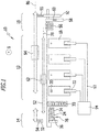
- An embodiment of a machine tool system according to the invention which in the Figures 1 to 5 and is denoted there by 10, comprises a processing area 12, a supply area 14 and a discharge area 16.
- the processing area 12 includes one and in particular a plurality of machine tools 18.
- the machine tools 18 are in particular arranged next to one another.
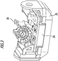
- a machine tool 18 comprises a workpiece holding device 20 (cf. also Figure 3 ), which holds the one or more workpieces in the machine tool 18 when machining one or more workpieces.
- a Machine tool 18 further comprises a tool carrier device 22 which holds one or more tools during workpiece machining on the corresponding machine tool 18.
- the tool carrier device 22 comprises in particular one or more tool spindles.
- the workpiece is machined, in particular by machining.
- a workpiece that is machined on a machine tool 18 is a metallic workpiece.
- the machine tools 18 are designed as machining centers, for example.
- a mobility of the tool carrier device 22 with respect to the workpiece holding device 20 comprises linear axes and one or more pivot axes or axes of rotation. For example, relative mobility between a machined workpiece and a tool is implemented in five axes.
- an adapter 24 (cf. Figure 3 ) held on the corresponding workpiece holding device 20.
- a workpiece 26 is clamped onto the corresponding adapter 24.
- the adapter 24, in turn, is clamped on the workpiece holding device 20.
- the adapter 24, which is designed in particular as an adapter plate (pallet), enables different workpieces to be fixed to the workpiece holding device 20 without converting or replacing the workpiece holding device 20.
- An adapter 24 provides an interface between the workpiece 26 and the workpiece holding device 20.
- Workpiece blanks are provided to the machining area 12 via the feed area 14 for machining.
- the feed area 14 comprises a positioning device 28.
- workpiece blanks are positioned on adapters 24.
- they are also fixed there on corresponding adapters 24 on a clamping station, that is to say clamped with them.
- the feed area 14 comprises a storage device 30 which has adapters 24 ready. It is fundamentally possible for only empty adapters 24, only adapters 24 loaded with workpiece blanks, or both empty adapters 24 and loaded adapters 24 to be kept ready on the storage device 30.
- the feed area 14 is connected to a belt 32 via which workpiece blanks are supplied.
- the feed area 14 and in particular the positioning device 28 include a cleaning device 34.
- the cleaning device 34 adapters 24 in particular are cleaned, for example by rinsing.
- the feed area 14 comprises an embossing device 36 which, for example, comprises one or more writing units, for example with a needle embossing device.
- embossing device 36 At the embossing device 36, the processing machine tool 18 and an adapter number (in particular after fixing a workpiece blank on the corresponding adapter 24) are embossed into the workpiece by a corresponding writing unit.
- the positioning device 28 comprises a workpiece gripping device 38 ( Figure 2 ).
- This workpiece gripping device 38 of the positioning device 28 has at least one gripper 40.
- This gripper 40 is linearly displaceable in a height direction 42, which is related to the direction of gravity g (in Figure 2 if the direction of gravity is perpendicular to the plane of the drawing), it is in particular a vertical direction. Further, the gripper 40 is in a linear one
- the direction 44 is displaceable transversely and in particular perpendicular to the height direction 42.
- the linear direction 44 is in particular a horizontal direction in relation to the direction of gravity g.
- the gripper 40 can be rotated or pivoted about a first axis of rotation 46 (C-axis), which in particular lies transversely and preferably perpendicular to the height direction 42 and transversely and in particular perpendicular to the linear direction 44.
- C-axis first axis of rotation 46
- the gripper 40 is rotatable or pivotable about a second axis of rotation 48 (bucket axis).
- the second axis of rotation 48 lies, for example, parallel to the linear direction 44.
- the gripper (I-gripper) of the workpiece gripping device 38 allows a workpiece blank to be picked up from the belt 32 and placed on an adapter 24 that is kept ready, where it is then clamped in particular with the adapter 24.
- the gripper 40 picks up a workpiece blank on the front side, causes a pivoting about the second axis of rotation 48 and a pivoting about the first axis of rotation 46.
- the corresponding data is then attached to the workpiece blank at the embossing device 36, as described above.
- the workpiece blank is then placed on the adapter 24 and clamped to it.
- Adapters 24 are provided by the storage device 30.
- the discharge area 16 serves to discharge workpieces processed by the machine tools 18.
- the removal area 16 comprises a belt 50, by means of which processed workpieces are removed and, in particular, are removed to a next processing unit.
- a main transport direction of workpieces between the feed area 14, the processing area 12 and the discharge area 16 is a linear direction 52 (cf. Figure 1 ).
- This linear direction 52 is in particular parallel to the linear direction 44.
- a feed direction 54 of the strip 32 lies transversely to the linear direction 52 and, in particular, perpendicular to it.
- the machine tool system 10 can thereby be implemented in a compact manner.
- a removal direction 55 of the belt 50 lies transversely and in particular perpendicular to the linear direction 52 in order to be able to implement a compact machine tool system 10.
- a discharge direction 60 is in particular transverse and preferably perpendicular to the linear direction 52.
- the workpiece gripping device 38 which is assigned to the positioning device 28, ensures the transport of workpiece blanks between the belt 32 and the positioning device 28. Via the workpiece gripping device 38, workpiece blanks are deposited on provided adapters 24 and clamped there.
- an adapter loading transport device 62 For workpiece communication between the feed area 14 and the processing area 12, within the processing area 12 and between the processing area 12 and the discharge area 16, an adapter loading transport device 62 is provided, and a workpiece transport device 64 is provided.
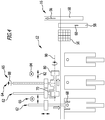
- the adapter loading transport device 62 comprises an adapter gripping device 66 ( Figures 2 , 4th ), which engages an adapter 24 and can grasp and hold it.
- the adapter gripping device 66 has a first gripper 68 and a second gripper 70.
- the first gripper 68 and the second gripper 70 can each be moved linearly in a first direction 72 and in a second direction 74.
- the second direction 74 lies transversely and in particular perpendicular to the first direction 72.
- the first direction 72 lies in particular parallel to the linear direction 52.
- the first direction 72 is a horizontal direction with respect to the direction of gravity g and the second direction 74 is a vertical direction.
- first gripper 68 and the second gripper 70 are movable in a third direction 76.
- This third direction 76 lies transversely and in particular perpendicular to the first direction 72 and transversely and in particular perpendicular to the second direction 74.
- the third direction 76 is, in particular, a horizontal direction in relation to the direction of gravity g.
- first gripper 68 and the second gripper 70 are arranged in a group, so that they are mechanically connected to one another, for example, with regard to mobility in the first direction 72 and / or in the second direction 74 or by a corresponding software solution in a control are "virtually" connected to each other.
- the first gripper 68 and the second gripper 70 are designed in such a way that they each engage an adapter 24 (see FIG Figure 5 ) and not on a workpiece.
- the first gripper 68 or the second gripper 70 contacts the corresponding adapter 24 and clamps it in place. He holds it and can transport it.
- Workpiece blanks are gripped by the positioning device 28 via the adapter loading transport device 62. As already mentioned above, the attack takes place on the corresponding adapter 24 on which the workpiece blank or blanks are arranged.
- the adapter 24 with the workpiece blank (s) is then moved in a first movement axis 78, which runs along a distance direction (in the linear direction 52) between the feed area 14 and the processing area 12 and thus in the distance direction between the positioning device 28 and which runs in particular machine tools 18 arranged in a row, are transported to the corresponding machine tool 18.
- the adapter 24 with the work piece (s) is then loaded into the corresponding machine tool 18 by the adapter loading transport device 62.
- the corresponding machine tool 18 is loaded from above in relation to the direction of gravity g.
- the corresponding gripper 68 or 70 after being positioned on the corresponding machine tool 18 by moving in the first direction 72 and positioned at the corresponding height by moving in the second direction 74, travels in the third direction 76 over the corresponding work space.
- the corresponding gripper 68 or 70 with the adapter 24 loaded with one or more workpiece blanks is then moved onto the workpiece holding device 20 from above.
- the corresponding adapter 24 is used on the workpiece holding device 20 and clamped to it there.
- the corresponding gripper 68 or 70 of the adapter loading transport device 62 removes the adapter 24 with the machined work piece (s) from the corresponding machine tool 18 positioned and then driven down in the direction 74.
- the corresponding adapter 24 (with the machined work piece (s)) is picked up and moved out of the machine tool 18.
- the adapter loading transport device 62 When the corresponding machine tool 18 is unloaded by the adapter loading transport device 62, the work piece (s) sit loosely on the adapter 24, as it were.
- the gripper 68 or 70 engages the adapter 24.
- the work piece or work pieces which sit “loosely” on the adapter 24 are supported by the latter.
- the adapter 24 still holds the machined work piece or pieces, but without clamping.
- the workpiece transport device 64 comprises a gripper 80 (I-gripper).
- This gripper 80 (see also Figure 5 ) is designed for gripping (grasping) machined workpieces. It is linearly displaceable in a first direction 82 and in a second direction 84 lying transversely thereto. The second direction 84 is in particular perpendicular to the first direction 82.
- the first direction 82 is a horizontal direction and the second direction 84 is a vertical direction with respect to the direction of gravity g.
- the first direction 82 is in particular parallel to the linear direction 52.
- the mobility in the first direction 82 defines a second movement axis 86 for the workpiece transport device 64.
- This second axis of movement 86 is in particular parallel to the first axis of movement 78 of the adapter loading transport device 62.
- the gripper 80 can be rotated or pivoted about a first axis of rotation 88, which in particular lies transversely and preferably perpendicular to the first direction 82 and the second direction 84.
- the gripper 80 is pivotable or rotatable about a second axis of rotation 90.
- the second axis of rotation 90 forms, in particular, a bucket axis.
- the second axis of rotation 90 lies in particular parallel to the first direction 82.
- the gripper 80 is linearly displaceable in a third direction perpendicular to the first direction 82 and perpendicular to the second direction 84. With a corresponding design of the adapter-loading-transport device 82, such displaceability in the third direction does not have to be provided.
- the gripper 80 is basically designed in the same way as the gripper 40 of the workpiece gripping device 38 and, in one exemplary embodiment, has the same forms of movement.
- the workpiece transport device 64 is used to transport workpieces from the processing area 12 into the discharge area 16.
- the adapter gripping device 66 of the adapter loading transport device 62 and the gripper 80 of the workpiece transport device 64 have an overlapping movement space.
- the workpiece transport device 64 is designed in such a way that it can remove workpieces provided by the adapter gripping device 66 outside the machine tools 18 and from the removal area 16 by appropriate displacement and can optionally provide alignment via rotation about the first axis of rotation 88 and / or the second axis of rotation 90.
- the adapter gripping device 66 provides an adapter 24 with one or more machined workpieces seated thereon, with these being released.
- the gripper 80 of the workpiece transport device 64 then grips the corresponding machined work piece (s) (cf. Figure 5 ).
- a removal from the adapter 24 then takes place.
- the removal takes place by a relative movement of the gripper 80 to the corresponding gripper 68 or 70, which holds the adapter.
- the gripper 80 which holds the machined workpiece, then feeds it to the discharge area 16.
- the corresponding adapter gripping device 66 holds an "empty", that is to say unloaded, adapter with the first gripper 68 or the second gripper 70.
- the machine tools 18 of the machining area 12 have a hydraulic system 92, which is used in particular to release workpieces from adapters 24 within the machine tools 18 when the corresponding adapter 24 is still clamped to the respective workpiece holding device 20.
- This hydraulic system 92 comprises, in particular, a common hydraulic unit 94 with a corresponding hydraulic oil supply, via which a plurality of machine tools 18 are operated.
- a compact machine tool system 10 can be implemented by means of such a “central” hydraulic unit 94.
- the machine tool system 10 is operated as follows: On the positioning device 28, one or more workpiece blanks are positioned and in particular also fixed in place via the workpiece gripping device 38 on corresponding adapters 24.
- the positioning device 28 includes a corresponding tensioning station for this purpose. With a corresponding mobility of the gripper 40, in addition to the positioning, a corresponding alignment can also take place compared to a delivery state of workpiece blanks via the belt 32.
- the adapter gripping device 36 picks up a "clamped" adapter 24 via a gripper (such as, for example) the gripper 70, that is to say picks up an adapter 24 on which one or more workpieces are clamped.
- the other gripper such as, for example, the first gripper 68, holds an “empty” adapter, which is delivered to the positioning device 28 after the loaded adapter has been picked up. This is cleaned at the cleaning device 34 before it is loaded with a workpiece blank.
- the adapter gripping device 66 fetches the corresponding adapter 24 with the machined work piece (s) from the corresponding machine tool 18.
- the machined work piece (s) is relaxed from the adapter 24 when the Adapter 24 is still seated on the corresponding workpiece holding device 20 of the corresponding machine tool 18.
- the adapter 24 supports the workpiece and still holds it, but relaxed.
- the adapter gripping device 66 provides the machined work piece (s), which are still arranged on the corresponding adapter 24, to the workpiece transport device with its workpiece gripping device 65 with the gripper 80.
- the gripper 80 engages the workpiece or workpieces being processed.
- the work piece (s) are held on the gripper 80 and the processed work piece (s) is made available to the discharge area 16 by a corresponding movement.
- the corresponding gripper of the adapter gripping device 66 now holds an unloaded adapter 24, which is again made available to the positioning device 28 by a corresponding movement.
- the machined workpieces are, for example, cylinder crankcases.
- the solution according to the invention provides a flexible interface for transferring the workpiece. Short system cycle times can be achieved, with loss of set-up times being minimized.
- the alignment (via the workpiece gripping device 38 of the positioning device 28) and the clamping of workpiece blanks on adapters 24 takes place separately from the processing area 12.
- the workpiece transfer between the adapter loading transport device 62 and the workpiece transport device 64 takes place according to a "shake" Hand principle ". This enables short system cycle times to be achieved.
- the number of necessary adapters 24 can be kept low. In principle, no massive conversion of the machine tools 18 is necessary. For example, in the exemplary embodiment in which workpieces are relaxed from adapters 24 within machine tools 18 on the corresponding workpiece holding device 20, a corresponding design of the workpiece holding device 20 is sufficient.
- the system can be flexibly adapted to different workpiece types.
- the loading and unloading of the machine tools 18 is the most critical.
- the system cycle time the loading and unloading of the machine tools 18 is the most critical.
- the grippers 68, 70 By using at least two grippers 68, 70, short system cycle times can be achieved.
Description
Die Erfindung betrifft ein Werkzeugmaschinensystem, umfassend mindestens eine Werkzeugmaschine zur Bearbeitung von Werkstücken, mit einer Werkstückhalteeinrichtung, wobei bei einer Werkstückbearbeitung ein oder mehrere Werkstücke über einen Adapter an der Werkstückhalteeinrichtung gehalten sind.The invention relates to a machine tool system, comprising at least one machine tool for machining workpieces, with a workpiece holding device, one or more workpieces being held on the workpiece holding device via an adapter during workpiece machining.
Die Erfindung betrifft ferner ein Verfahren zum Betreiben eines Werkzeugmaschinensystems, welches mindestens eine Werkzeugmaschine umfasst, wobei bei einer Werkstückbearbeitung an der mindestens einen Werkzeugmaschine ein oder mehrere Werkstücke über einen Adapter an einer Werkstückhalteeinrichtung gehalten werden.The invention further relates to a method for operating a machine tool system which comprises at least one machine tool, one or more workpieces being held on a workpiece holding device via an adapter during workpiece machining on the at least one machine tool.
Bei Werkzeugmaschinensystemen, bei denen Werkstücke nicht direkt an einer Werkstückhalteeinrichtung einer Werkzeugmaschine gehalten werden, sondern mittels eines Adapters, lassen sich minimierte Umrüstzeiten realisieren, wenn unterschiedliche Werkstücke bearbeitet werden sollen. Durch Verwendung geeigneter Adapter kann die gleiche Werkstückhalteeinrichtung ohne Umbau oder dergleichen für unterschiedliche Werkstücke verwendet werden.In machine tool systems in which workpieces are not held directly on a workpiece holding device of a machine tool, but rather by means of an adapter, it is possible to achieve minimized changeover times when different workpieces are to be machined. By using suitable adapters, the same workpiece holding device can be used for different workpieces without conversion or the like.
Die
Aus der
Aus der
Der Erfindung liegt die Aufgabe zugrunde, ein Werkzeugmaschinensystem der eingangs genannten Art und ein Verfahren der eingangs genannten Art bereitzustellen, welches minimierte Systemtaktzeiten aufweist.The invention is based on the object of providing a machine tool system of the type mentioned at the beginning and a method of the type mentioned at the beginning which has minimized system cycle times.
Diese Aufgabe wird bei dem eingangs genannten Werkzeugmaschinensystem erfindungsgemäß dadurch gelöst, dass eine Positioniereinrichtung vorgesehen ist, welche Werkstückrohlinge an Adaptern positioniert, eine Adapter-Lade-Transporteinrichtung vorgesehen ist, mit einer Adapter-Greifeinrichtung, welche an Adaptern angreift, wobei die Adapter-Lade-Transporteinrichtung mit Werkstückrohlingen versehene Adapter von der Positioniereinrichtung zu der mindestens einen Werkzeugmaschine bringt, die mindestens eine Werkzeugmaschine belädt und mit einem oder mehreren bearbeiteten Werkstücken versehene Adapter von der mindestens einen Werkzeugmaschine entlädt, und eine Werkstück-Transporteinrichtung vorgesehen ist mit einer Werkstück-Greifeinrichtung, welche an Werkstücken angreift, wobei die Werkstück-Transporteinrichtung bearbeitete Werkstücke nach Entladung an der mindestens einen Werkzeugmaschine durch die Adapter-Lade-Transporteinrichtung von der Adapter-Lade-Transporteinrichtung übernimmt und abführt, und dass die Werkstückhalteeinrichtung ein Lösesystem zum Lösen einer Spannung von einem oder mehreren bearbeiteten Werkstücken an einem Adapter umfasst und/oder ein Spannsystem zum Spannen eines oder mehrerer Werkstücke an dem Adapter umfasst, wobei bearbeitete Werkstücke, welche an Adaptern positioniert sind, innerhalb der mindestens einen Werkzeugmaschine von dem Adapter entspannbar sind und/oder Werkstücke, welche an Adaptern positioniert sind, innerhalb der Werkzeugmaschine an den Adaptern spannbar sind.In the machine tool system mentioned at the beginning, this object is achieved according to the invention in that a positioning device is provided which positions workpiece blanks on adapters, an adapter loading transport device is provided with an adapter gripping device which engages adapters, the adapter loading Transport device brings adapters provided with workpiece blanks from the positioning device to the at least one machine tool, which loads at least one machine tool and unloads adapters provided with one or more machined workpieces from the at least one machine tool, and a workpiece transport device is provided with a workpiece gripping device which attacks on workpieces, the workpiece transport device taking over and removing machined workpieces after unloading on the at least one machine tool by the adapter loading transport device from the adapter loading transport device leads, and that the workpiece holding device comprises a release system for releasing a clamping of one or more machined workpieces on an adapter and / or comprises a clamping system for clamping one or more workpieces on the adapter, wherein machined workpieces which are positioned on adapters, within the at least one machine tool can be released from the adapter and / or workpieces that are positioned on adapters can be clamped on the adapters within the machine tool.
Bei der erfindungsgemäßen Lösung wird gemäß einem "Shake-Hand-Prinzip" ein bearbeitetes Werkstück nach Entladung der mindestens einen Werkzeugmaschine von der Adapter-Lade-Transporteinrichtung an die Werkstück-Transporteinrichtung übergeben.In the solution according to the invention, a machined workpiece is transferred from the adapter loading transport device to the workpiece transport device after the at least one machine tool has been unloaded according to a “shake hand principle”.
Das Beladen der mindestens einen Werkzeugmaschine und das Entladen lassen sich auf effektive Weise durchführen. Die Übergabe an die Werkstück-Greifeinrichtung von bearbeiteten Werkstücken kann außerhalb der mindestens einen Werkzeugmaschine erfolgen. Es lassen sich so insgesamt Systemtaktzeiten und Rüstzeiten minimieren.The loading of the at least one machine tool and the unloading can be carried out in an effective manner. The transfer of processed workpieces to the workpiece gripping device can take place outside of the at least one machine tool. In this way, overall system cycle times and set-up times can be minimized.
Ein "Umbau" der mindestens einen Werkzeugmaschine kann minimal gehalten werden. Es lassen sich dadurch beispielsweise auch Fünf-Achs-Bearbeitungsvorgänge an der mindestens einen Werkzeugmaschine durchführen.A “conversion” of the at least one machine tool can be kept to a minimum. In this way, for example, five-axis machining operations can also be carried out on the at least one machine tool.
Das erfindungsgemäße Werkzeugmaschinensystem ist flexibel einsetzbar und anpassbar.The machine tool system according to the invention can be used flexibly and adapted.
Günstig ist es, wenn die Werkstück-Transporteinrichtung bearbeitete Werkstücke außerhalb der mindestens einen Werkzeugmaschine von der Adapter-Lade-Transporteinrichtung übernimmt. Dadurch lassen sich kurze Systemtaktzeiten erreichen.It is favorable if the workpiece transport device accepts processed workpieces outside the at least one machine tool from the adapter loading transport device. This enables short system cycle times to be achieved.
Bei einem Ausführungsbeispiel umfasst die Adapter-Greifeinrichtung mindestens zwei Greifer. Dadurch lassen sich kurze Systemtaktzeiten realisieren. Beispielsweise kann ein Greifer einen mit einem oder mehreren Werkstückrohlingen beladenen Adapter halten und der andere Greifer kann einen "leeren" Adapter halten.In one embodiment, the adapter gripping device comprises at least two grippers. This enables short system cycle times to be achieved. For example, one gripper can hold an adapter loaded with one or more workpiece blanks and the other gripper can hold an "empty" adapter.
Bei einem konstruktiv einfachen Ausführungsbeispiel ist vorgesehen, dass die mindestens zwei Greifer miteinander verbunden sind und gemeinsam zumindest in einer Bewegungsachse bewegt sind. Die Verbindung kann dabei mechanisch sein oder es kann sich um eine softwaremäßige Verbindung in einer Steuerung handeln.In a structurally simple embodiment, it is provided that the at least two grippers are connected to one another and are moved together at least in one movement axis. The connection can be mechanical or it can be a software connection in a controller.
Günstig ist es, wenn ein Greifer der Adapter-Greifeinrichtung eine Linearbeweglichkeit in einer ersten Richtung aufweist und in einer zweiten Richtung quer zu der ersten Richtung aufweist. Es kann ferner eine Linearbeweglichkeit in einer dritten Richtung quer zur ersten Richtung und quer zur zweiten Richtung vorgesehen sein. Dadurch lässt sich auf effektive Weise die mindestens eine Werkzeugmaschine anfahren und es lässt sich die Positioniereinrichtung anfahren. Es lässt sich auf effektive Weise eine Beladung der mindestens einen Werkzeugmaschine erreichen und eine Entladung der mindestens einen Werkzeugmaschine. Ferner lässt sich auf einfache Weise eine Übergabe an die Werkstück-Greifeinrichtung realisieren.It is favorable if a gripper of the adapter gripping device has a linear mobility in a first direction and has a second direction transverse to the first direction. Furthermore, linear mobility in a third direction transverse to the first direction and transverse to the second direction can be provided. As a result, the at least one machine tool can be approached in an effective manner and the positioning device can be approached. Loading of the at least one machine tool and unloading of the machine tool can be achieved in an effective manner at least one machine tool. Furthermore, a transfer to the workpiece gripping device can be implemented in a simple manner.
Bei einem Ausführungsbeispiel ist die erste Achse bezogen auf die Schwerkraftrichtung eine horizontale Richtung. Es ist dann ferner günstig, wenn die zweite Richtung bezogen auf die Schwerkraftrichtung eine vertikale Richtung ist. Dadurch lässt sich das Werkzeugmaschinensystem auf einfache und kompakte Weise realisieren.In one embodiment, the first axis is a horizontal direction with respect to the direction of gravity. It is then also advantageous if the second direction is a vertical direction in relation to the direction of gravity. This allows the machine tool system to be implemented in a simple and compact manner.
Es ist günstig, wenn die Werkstück-Greifeinrichtung der Werkstück-Transporteinrichtung mindestens einen Greifer umfasst. Dieser Greifer, welcher an einem Werkstück angreift, kann dann auf effektive Weise ein Werkstück von der Adapter-Greifeinrichtung übernehmen und dabei auch von dem entsprechenden Adapter abheben.It is favorable if the workpiece gripping device of the workpiece transport device comprises at least one gripper. This gripper, which engages a workpiece, can then effectively take over a workpiece from the adapter gripping device and in the process also lift off the corresponding adapter.
Es ist ebenfalls günstig, wenn die Positioniereinrichtung eine Werkstück-Greifeinrichtung mit mindestens einem Greifer umfasst, welcher an Werkstückrohlingen angreift. Über diesen mindestens einen Greifer können Werkstückrohlinge beispielsweise von einem Zuführband entnommen werden und an der Positioniereinrichtung auf Adaptern abgelegt werden.It is also favorable if the positioning device comprises a workpiece gripping device with at least one gripper which engages workpiece blanks. Via this at least one gripper, workpiece blanks can be removed from a feed belt, for example, and placed on adapters at the positioning device.
Es ist insbesondere günstig, wenn ein Greifer der Werkstück-Transporteinrichtung und/oder der Positioniereinrichtung in einer ersten Richtung und einer zweiten Richtung quer zur ersten Richtung linear verschieblich ist. Dadurch ergibt sich eine entsprechende Beweglichkeit, um Werkstückrohlinge an der Positioniereinrichtung zu positionieren beziehungsweise bearbeitete Werkstücke beispielsweise an einem Abführband zu positionieren.It is particularly favorable if a gripper of the workpiece transport device and / or the positioning device is linearly displaceable in a first direction and a second direction transverse to the first direction. This results in a corresponding mobility in order to position workpiece blanks on the positioning device or to position processed workpieces, for example, on a discharge belt.
Es ist ferner günstig, wenn ein Greifer der Werkstück-Transporteinrichtung und/oder der Positioniereinrichtung um eine erste Drehachse schwenkbar oder drehbar ist. Dadurch lässt sich eine entsprechende Ausrichtung beziehungsweise Positionierung von Werkstücken (vor beziehungsweise nach der Bearbeitung) erreichen.It is also favorable if a gripper of the workpiece transport device and / or the positioning device can be pivoted or rotated about a first axis of rotation. In this way, a corresponding alignment or positioning of workpieces (before or after processing) can be achieved.
Aus dem gleichen Grund ist es günstig, wenn der Greifer der Werkstück-Transporteinrichtung und/oder der Positioniereinrichtung um eine zweite Drehachse schwenkbar oder drehbar ist, welche verschieden von der ersten Drehachse und insbesondere quer zu dieser orientiert ist. Durch die Drehbarkeit beziehungsweise Schwenkbarkeit um die erste Drehachse und/oder zweite Drehachse kann ein Werkstück (ein Werkstückrohling beziehungsweise bearbeitetes Werkstück) gegriffen werden und dann entsprechend transportiert werden und bei der Entnahme beziehungsweise Ablage kann die geeignete Ausrichtung erfolgen.For the same reason, it is advantageous if the gripper of the workpiece transport device and / or the positioning device can be pivoted or rotated about a second axis of rotation which is different from the first axis of rotation and, in particular, is oriented transversely to it. As it can be rotated or pivoted about the first axis of rotation and / or the second axis of rotation, a workpiece (a workpiece blank or machined workpiece) can be gripped and then transported accordingly and the appropriate alignment can take place during removal or storage.
Insbesondere weist die Adapter-Greifeinrichtung eine erste Bewegungsachse auf, welche entlang einer Abstandsrichtung zwischen der Positioniereinrichtung und der mindestens einen Werkzeugmaschine liegt. Dadurch lassen sich Adapter, welche mit einem oder mehreren Werkstücken beladen sind, von der Positioniereinrichtung zu der mindestens einen Werkzeugmaschine bringen. Ferner lassen sich "leere" Adapter, welche mittels der Werkstück-Greifeinrichtung der Werkstück-Transporteinrichtung entladen wurden, wieder der Positioniereinrichtung zur neuen Beladung zuführen.In particular, the adapter gripping device has a first axis of movement which lies along a distance direction between the positioning device and the at least one machine tool. As a result, adapters which are loaded with one or more workpieces can be brought from the positioning device to the at least one machine tool. Furthermore, "empty" adapters, which have been unloaded by means of the workpiece gripping device of the workpiece transport device, can be fed back to the positioning device for reloading.
Es ist ferner günstig, wenn die Werkstück-Greifeinrichtung der Werkstück-Transporteinrichtung eine zweite Bewegungsachse aufweist, welche entlang einer Abstandsrichtung zwischen der mindestens einen Werkzeugmaschine und einer Abführungseinrichtung für bearbeitete Werkstücke liegt. Dadurch lassen sich bearbeitete Werkstücke auf effektive Weise abführen. Ferner lässt sich dadurch auf einfache Weise eine Übergabe von bearbeiteten Werkstücken von der Adapter-Lade-Transporteinrichtung zu der Werkstück-Transporteinrichtung realisieren.It is also favorable if the workpiece gripping device of the workpiece transport device has a second movement axis which lies along a distance direction between the at least one machine tool and a discharge device for processed workpieces. This allows processed workpieces to be removed effectively. Furthermore, a transfer of processed workpieces from the adapter loading transport device to the workpiece transport device can thereby be implemented in a simple manner.
Es ist dann günstig, wenn die zweite Bewegungsachse parallel zu einer ersten Bewegungsachse der Adapter-Greifeinrichtung liegt. Dadurch lässt sich das erfindungsgemäße Werkzeugmaschinensystem auf kompakte Weise und konstruktiv günstige Weise realisieren.It is then advantageous if the second axis of movement lies parallel to a first axis of movement of the adapter gripping device. As a result, the machine tool system according to the invention can be implemented in a compact and structurally favorable manner.
Die Werkstückhalteeinrichtung ist so ausgebildet, dass bearbeitete Werkstücke, welche an Adaptern positioniert sind, innerhalb der mindestens einen Werkzeugmaschine von dem Adapter entspannbar sind und/oder Werkstücke, welche an Adaptern positioniert sind, innerhalb der Werkzeugmaschine an Adaptern spannbar sind. Dadurch lässt sich unter geringem konstruktivem Aufwand ein erfindungsgemäßes Werkzeugmaschinensystem realisieren. Die Adapter-Greifeinrichtung beziehungsweise die Werkstück-Greifeinrichtung lässt sich mit konstruktiv geringem Aufwand realisieren, da an diesen keine Entspannung von Werkstücken von Adaptern beziehungsweise Spannung von Werkstücken an Adaptern vorgesehen werden muss.The workpiece holding device is designed such that machined workpieces that are positioned on adapters can be released from the adapter within the at least one machine tool and / or workpieces that are positioned on adapters can be clamped on adapters within the machine tool. As a result, a machine tool system according to the invention can be implemented with little constructive effort. The adapter gripping device or the workpiece gripping device can be implemented with little constructive effort, since there is no need to provide relaxation of workpieces on adapters or tensioning of workpieces on adapters on these.
Es ist ferner günstig, wenn die Werkstück-Greifeinrichtung der Werkstück-Transporteinrichtung einen Bewegungsraum aufweist, welcher in einem Bewegungsraum der Adapter-Greifeinrichtung liegt und bearbeitete Werkstücke von der Adapter-Greifeinrichtung an die Werkstück-Greifeinrichtung zu übergeben. Durch überlappende Bewegungsräume lässt sich eine Werkstückübergabe nach dem "Shake-Hand-Prinzip" auf einfache Weise realisieren.It is also advantageous if the workpiece gripping device of the workpiece transport device has a movement space which is located in a movement space of the adapter gripping device and to transfer processed workpieces from the adapter gripping device to the workpiece gripping device. Overlapping movement spaces make it easy to transfer the workpiece according to the "shake-hand principle".
Bei einem Ausführungsbeispiel ist eine Mehrzahl von Werkzeugmaschinen vorgesehen. In den Werkzeugmaschinen erfolgt beispielsweise gleichzeitig eine Bearbeitung einer Mehrzahl von Werkstücken, wobei in unterschiedlichen Werkzeugmaschinen grundsätzlich unterschiedliche Bearbeitungsvorgänge stattfinden können oder gleiche Bearbeitungsvorgänge und insbesondere eine Parallelbearbeitung stattfinden kann. Durch die Adapter-Lade-Transporteinrichtung und durch die Werkstück-Transporteinrichtung lassen sich diese Werkzeugmaschinen anfahren, beladen und entladen und es lassen sich bearbeitete Werkstücke abführen.In one embodiment, a plurality of machine tools are provided. In the machine tools, for example, a plurality of workpieces are machined at the same time, wherein in different machine tools, in principle, different machining operations can take place or the same machining operations and in particular parallel machining can take place. These machine tools can be approached, loaded and unloaded through the adapter loading transport device and through the workpiece transport device, and processed workpieces can be removed.
Es ist günstig, wenn ein Hydrauliksystem für die Werkzeugmaschinen vorgesehen ist. Dieses Hydrauliksystem dient insbesondere zum Spannen beziehungsweise Lösen von Werkstücken an Adaptern innerhalb von Werkzeugmaschinen. Durch ein gemeinsames Hydrauliksystem für die Werkzeugmaschinen lässt sich der konstruktive Aufwand gering halten.It is advantageous if a hydraulic system is provided for the machine tools. This hydraulic system is used in particular to clamp or loosen workpieces on adapters within machine tools. A common hydraulic system for the machine tools means that the design effort can be kept low.
Insbesondere ist ein gemeinsames Hydraulikaggregat und insbesondere gemeinsamer Hydraulikölvorrat für die Werkzeugmaschinen der Mehrzahl von Werkzeugmaschinen vorgesehen. Dadurch lässt sich der konstruktive Aufwand gering halten.In particular, a common hydraulic unit and, in particular, a common hydraulic oil supply are provided for the machine tools of the plurality of machine tools. This allows the design effort to be kept low.
Insbesondere sind Werkstückhalteeinrichtungen der Werkzeugmaschinen an das Hydrauliksystem angeschlossen. Dadurch lässt sich an den Werkstückhalteeinrichtungen innerhalb einer Werkzeugmaschine ein an einem Adapter eingespanntes Werkstück lösen oder bei einem Ausführungsbeispiel lässt sich ein an einem Adapter angeordnetes Werkstück mit diesem verspannen. Dadurch ist der Aufwand zum Lösen beziehungsweise zum Spannen außerhalb der mindestens einen Werkzeugmaschine verringert.In particular, workpiece holding devices of the machine tools are connected to the hydraulic system. As a result, a workpiece clamped on an adapter can be released on the workpiece holding devices within a machine tool or, in one embodiment, a workpiece arranged on an adapter can be clamped to the adapter. As a result, the effort for releasing or clamping outside the at least one machine tool is reduced.
Es ist ferner günstig, wenn eine Speichereinrichtung für Adapter vorgesehen ist, welche Adapter der Positioniereinrichtung bereitstellt. Es kann so eine effektive Positionierung und insbesondere auch Einspannung von Werkstücken an Adaptern erfolgen.It is also advantageous if a storage device is provided for adapters which provides adapters for the positioning device. Effective positioning and, in particular, also clamping of workpieces on adapters can thus take place.
Ein kompakt aufgebautes Werkzeugmaschinensystem lässt sich realisieren, wenn die Speichereinrichtung zwischen der Positioniereinrichtung und der mindestens einen Werkzeugmaschine angeordnet ist. Dadurch lassen sich auch die Verfahrwege für die Adapter-Lade-Transporteinrichtung minimieren, um beispielsweise leere (unbeladene) Adapter der Positioniereinrichtung bereitzustellen.A machine tool system with a compact structure can be implemented if the storage device is arranged between the positioning device and the at least one machine tool. As a result, the travel paths for the adapter-loading-transport device can also be minimized, for example in order to provide empty (unloaded) adapters for the positioning device.
Insbesondere ist die Speichereinrichtung durch die Adapter-Lade-Transporteinrichtung anfahrbar, um einen effektiven Transport von beladenen und unbeladenen Adaptern zu erreichen.In particular, the storage device can be approached by the adapter loading transport device in order to achieve effective transport of loaded and unloaded adapters.
Es ist günstig, wenn eine Reinigungseinrichtung für Adapter vorgesehen ist. Es lassen sich dann Adapter nach einer Werkstückbearbeitung reinigen und beispielsweise spülen.It is advantageous if a cleaning device is provided for adapters. Adapters can then be cleaned and, for example, rinsed after a workpiece has been processed.
Insbesondere ist die Reinigungseinrichtung durch die Adapter-Lade-Transporteinrichtung anfahrbar. Es ergeben sich so kurze Systemtaktzeiten.In particular, the cleaning device can be approached by the adapter loading transport device. This results in short system cycle times.
Es ist ferner günstig, wenn eine Prüfeinrichtung für bearbeitete Werkstücke und/oder eine Ausschleuseinrichtung für bearbeitete Werkstücke vorgesehen ist. Es lassen sich dadurch beispielsweise statistisch ausgewählte bearbeitete Werkstücke auf Fehlerhaftigkeit prüfen und gegebenenfalls vor der Weiterbearbeitung ausschließen.It is also advantageous if a test device for machined workpieces and / or a discharge device for machined workpieces is provided. In this way, for example, statistically selected machined workpieces can be checked for defects and, if necessary, excluded before further machining.
Insbesondere ist dann die Prüfeinrichtung und/oder die Ausschleuseinrichtung durch die Werkstück-Transporteinrichtung anfahrbar. Dadurch ergeben sich kurze Systemtaktzeiten.In particular, the testing device and / or the discharge device can then be approached by the workpiece transport device. This results in short system cycle times.
Die eingangs genannte Aufgabe wird bei dem eingangs genannten Verfahren erfindungsgemäß dadurch gelöst, dass das Verfahren folgende Schritte umfasst: Greifen eines mit einem oder mehreren Werkstückrohlingen versehenen Adapters durch eine Adapter-Greifeinrichtung; Zuführen des Adapters zu der mindestens einen Werkzeugmaschine durch die Adapter-Greifeinrichtung; Beladen der mindestens einen Werkzeugmaschine mit dem Adapter durch die Adapter-Greifeinrichtung und nach der Werkstückbearbeitung Entladung der mindestens einen Werkzeugmaschine durch Greifen des Adapters durch die Adapter-Greifeinrichtung, wobei das Werkstück oder die Werkstücke nach der Bearbeitung innerhalb der mindestens einen Werkzeugmaschine von dem Adapter entspannt werden, Greifen des oder der bearbeiteten Werkstücke, welche an dem Adapter sitzen, wobei der Adapter durch die Adapter-Greifeinrichtung gehalten wird, von einer Werkstück-Greifeinrichtung; Übernahme des oder der Werkstücke von der Adapter-Greifeinrichtung; und Abführung des Werkstücks oder der Werkstücke mit der Werkstück-Greifeinrichtung.The object mentioned at the beginning is achieved according to the invention in the method mentioned at the beginning in that the method comprises the following steps: gripping an adapter provided with one or more workpiece blanks by an adapter gripping device; Feeding the adapter to the at least one machine tool by the adapter gripping device; The adapter gripping device loads the at least one machine tool with the adapter and, after machining the workpiece, unloading the at least one machine tool by gripping the adapter with the adapter gripping device, the workpiece or workpieces being released from the adapter after machining within the at least one machine tool gripping the machined work piece (s) which are seated on the adapter, the adapter being held by the adapter gripping device, by a workpiece gripping device; Takeover of the work piece (s) from the adapter gripping device; and removing the workpiece or the workpieces with the workpiece gripping device.
Das erfindungsgemäße Verfahren weist die bereits im Zusammenhang mit dem erfindungsgemäßen Werkzeugmaschinensystem erläuterten Vorteile auf. Das erfindungsgemäße Verfahren ist an dem erfindungsgemäßen Werkzeugmaschinensystem durchführbar beziehungsweise das erfindungsgemäße Werkzeugmaschinensystem lässt sich mit dem erfindungsgemäßen Verfahren betreiben.The method according to the invention has the advantages already explained in connection with the machine tool system according to the invention. The method according to the invention can be carried out on the machine tool system according to the invention or the machine tool system according to the invention can be operated with the method according to the invention.
Insbesondere übernimmt die Werkstück-Greifeinrichtung das oder die bearbeiteten Werkstücke außerhalb der mindestens einen Werkzeugmaschine. Dadurch wird durch den Werkstücktransport außerhalb der Werkzeugmaschine der Bearbeitungsvorgang, welcher durch die mindestens eine Werkzeugmaschine durchführbar ist, nicht eingeschränkt. Beispielsweise sind Fünf-Achs-Bearbeitungsvorgänge durch die mindestens eine Werkzeugmaschine durchführbar.In particular, the workpiece gripping device takes over the machined work piece or pieces outside of the at least one machine tool. As a result, the machining process that can be carried out by the at least one machine tool is not restricted by the workpiece transport outside the machine tool. For example, five-axis machining operations can be carried out by the at least one machine tool.
Das Werkstück oder die Werkstücke werden nach der Bearbeitung innerhalb der mindestens einen Werkzeugmaschine von dem Adapter entspannt. Dadurch lässt sich die Werkstück-Greifeinrichtung und die Adapter-Greifeinrichtung mit geringem konstruktivem Aufwand ausbilden.The workpiece or the workpieces are relaxed from the adapter after machining within the at least one machine tool. As a result, the workpiece gripping device and the adapter gripping device can be designed with little constructive effort.
Die Werkstückhalteeinrichtung der mindestens einen Werkzeugmaschine umfasst ein Lösesystem zum Lösen einer Spannung von einem oder mehreren bearbeiteten Werkstücken an einem Adapter und/oder umfasst ein Spannsystem zum Spannen eines oder mehrerer Werkstücke und insbesondere Werkstückrohlinge an einem Adapter. Dadurch lässt sich ein Lösen beziehungsweise Spannen innerhalb der mindestens einen Werkzeugmaschine erreichen. Es kann dabei vorgesehen sein, dass das Lösen (Entspannen) innerhalb der mindestens einen Werkzeugmaschine erfolgt und das Spannen eines Werkstückrohlings an einem Adapter außerhalb der mindestens einen Werkzeugmaschine beispielsweise an einer Spannstation einer entsprechenden Positioniereinrichtung erfolgt.The workpiece holding device of the at least one machine tool comprises a release system for releasing a clamping of one or more machined workpieces on an adapter and / or comprises a clamping system for clamping one or more workpieces and in particular workpiece blanks on an adapter. As a result, loosening or clamping can be achieved within the at least one machine tool. It can be provided that the loosening (relaxing) takes place within the at least one machine tool and the clamping of a workpiece blank on an adapter outside of the at least one machine tool takes place, for example, at a clamping station of a corresponding positioning device.
Insbesondere ist bei Entladen der mindestens einen Werkzeugmaschine das oder die bearbeiteten Werkstücke an einem Adapter abgestützt. Der Adapter und das oder die Werkstücke sind entspannt voneinander, wobei der Adapter das Werkstück selber abstützt und dadurch hält. Dadurch kann die Adapter-Greifeinrichtung an dem Adapter angreifen und über die Werkstück-Greifeinrichtung kann das entspannte Werkstück von dem Adapter losgelöst und abgeführt werden und damit übernommen werden.In particular, when the at least one machine tool is unloaded, the machined work piece (s) is supported on an adapter. The adapter and the work piece or work pieces are relaxed from one another, the adapter supporting the work piece itself and thereby holding it. As a result, the adapter gripping device can grip the adapter and the relaxed workpiece can be detached from the adapter and removed via the workpiece gripping device and thus taken over.
Es kann vorgesehen sein, dass die Adapter-Greifeinrichtung mindestens einen ersten Greifer und einen zweiten Greifer aufweist, wobei mindestens in einem zeitlichen Teilbereich der erste Greifer einen leeren Adapter hält und der zweite Greifer ein mit einem oder mehreren Werkstücken beladenen Adapter hält. Dadurch lassen sich Systemtaktzeiten gering halten und Verfahrwege lassen sich gering halten.It can be provided that the adapter gripping device has at least a first gripper and a second gripper, the first gripper holding an empty adapter and the second gripper holding an adapter loaded with one or more workpieces at least in a partial range of time. As a result, system cycle times can be kept short and travel distances can be kept short.
Ganz besonders vorteilhaft ist es, wenn die mindestens eine Werkzeugmaschine durch die Adapter-Greifeinrichtung bezogen auf die Schwerkraftrichtung von oben her beladen wird und/oder entladen wird. Dadurch lassen sich ein Beladungsvorgang und ein Entladungsvorgang effektiv durchführen.It is particularly advantageous if the at least one machine tool is loaded and / or unloaded from above by the adapter gripping device in relation to the direction of gravity. Thereby, a loading process and an unloading process can be carried out effectively.
Bei einem Ausführungsbeispiel wird ein Greifer der Adapter-Greifeinrichtung und/oder ein Greifer der Werkstück-Greifeinrichtung in einer horizontalen Richtung und in einer vertikalen Richtung, bezogen auf die Schwerkraftrichtung, verfahren. Dadurch ergibt sich ein effektiver Transport beziehungsweise ein effektives Entladen und Beladen. Es kann insbesondere vorgesehen sein, dass ein Greifer der Adapter-Greifeinrichtung auch noch in einer weiteren horizontalen Richtung verfahrbar ist und dadurch in drei linear unabhängigen Linearrichtungen verfahrbar ist.In one embodiment, a gripper of the adapter gripping device and / or a gripper of the workpiece gripping device is moved in a horizontal direction and in a vertical direction, based on the direction of gravity. This results in effective transport or effective unloading and loading. In particular, it can be provided that a gripper of the adapter gripping device can also be moved in a further horizontal direction and, as a result, can be moved in three linearly independent linear directions.
Es ist ferner günstig, wenn ein Greifer der Werkstück-Greifeinrichtung um mindestens eine Drehachse gedreht oder geschwenkt wird. Dadurch lässt sich eine Ausrichtung von Werkstücken (als Rohling und/oder bearbeitetes Werkstück) erreichen. Dadurch ergibt sich eine effektive Positionierung an einem Adapter beziehungsweise es lässt sich auf einfache Weise eine Übergabe von der Adapter-Greifeinrichtung an die Werkstück-Greifeinrichtung erreichen.It is also advantageous if a gripper of the workpiece gripping device is rotated or pivoted about at least one axis of rotation. This allows workpieces to be aligned (as a blank and / or as a machined workpiece). This results in effective positioning on an adapter or a transfer from the adapter gripping device to the workpiece gripping device can be achieved in a simple manner.
Die nachfolgende Beschreibung bevorzugter Ausführungsformen dient im Zusammenhang mit den Zeichnungen der näheren Erläuterung der Erfindung. Es zeigen:
- Figur 1
- eine schematische Draufsicht auf ein Ausführungsbeispiel eines erfindungsgemäßen Werkzeugmaschinensystems (die Schwerkraftrichtung g liegt senkrecht zur Zeichenebene);
- Figur 2
- eine Detailansicht des Werkzeugmaschinensystems gemäß
Figur 1 in einem Zuführungsbereich für Werkstücke; - Figur 3
- eine schematische Darstellung eines Ausführungsbeispiels einer Werkzeughalteeinrichtung einer Werkzeugmaschine des Werkzeugmaschinensystems gemäß
Figur 1 , welche einen Adapter hält, an welchem wiederum ein Werkstück sitzt; - Figur 4
- eine Detailansicht des Werkzeugmaschinensystems gemäß
Figur 1 bei einer Werkstückübergabe; und - Figur 5
- eine schematische Darstellung von Greifern bei der Werkstückübergabe nach Bearbeitung des Werkstücks.
- Figure 1
- a schematic plan view of an embodiment of a machine tool system according to the invention (the direction of gravity g is perpendicular to the plane of the drawing);
- Figure 2
- a detailed view of the machine tool system according to
Figure 1 in a feed area for workpieces; - Figure 3
- a schematic representation of an embodiment of a tool holding device of a machine tool of the machine tool system according to FIG
Figure 1 which holds an adapter on which a workpiece is in turn; - Figure 4
- a detailed view of the machine tool system according to
Figure 1 when handing over a workpiece; and - Figure 5
- a schematic representation of grippers when the workpiece is transferred after the workpiece has been processed.
Ein Ausführungsbeispiel eines erfindungsgemäßen Werkzeugmaschinensystems, welches in den
Eine Werkzeugmaschine 18 umfasst eine Werkstückhalteeinrichtung 20 (vgl. auch
An einer Werkzeugmaschine 18 erfolgt eine Werkstückbearbeitung insbesondere durch spanabhebende Bearbeitung.On a
Beispielsweise ist ein Werkstück, welches an einer Werkzeugmaschine 18 bearbeitet wird, ein metallisches Werkstück.For example, a workpiece that is machined on a
Die Werkzeugmaschinen 18 sind beispielsweise als Bearbeitungszentren ausgebildet. Eine Beweglichkeit der Werkzeugträgereinrichtung 22 bezüglich der Werkstückhalteeinrichtung 20 umfasst Linearachsen und eine oder mehrere Schwenkachsen beziehungsweise Drehachsen. Beispielsweise ist eine relative Beweglichkeit zwischen einem bearbeiteten Werkstück und einem Werkzeug in fünf Achsen realisiert.The
Bei der Bearbeitung von Werkstücken an den jeweiligen Werkzeugmaschinen sind diese über einen Adapter 24 (vgl.
Über den Zuführungsbereich 14 werden dem Bearbeitungsbereich 12 Werkstückrohlinge zur Bearbeitung bereitgestellt.Workpiece blanks are provided to the
Der Zuführungsbereich 14 umfasst eine Positioniereinrichtung 28. An der Positioniereinrichtung 28 werden Werkstückrohlinge an Adaptern 24 positioniert. Insbesondere werden sie dort auch an entsprechenden Adaptern 24 an einer Spannstation fixiert, das heißt mit diesen verspannt.The
Der Zuführungsbereich 14 umfasst eine Speichereinrichtung 30, welche Adapter 24 bereithält. Es ist grundsätzlich möglich, dass an der Speichereinrichtung 30 nur leere Adapter 24, nur mit Werkstückrohlingen beladene Adapter 24, oder sowohl leere Adapter 24 als auch beladene Adapter 24 bereitgehalten werden.The
Bei einem Ausführungsbeispiel ist der Zuführungsbereich 14 an ein Band 32 angeschlossen, über welches Werkstückrohlinge geliefert werden.In one embodiment, the
Es kann auch vorgesehen sein, dass der Zuführungsbereich 14 und insbesondere die Positioniereinrichtung 28 eine Reinigungseinrichtung 34 umfasst. An der Reinigungseinrichtung 34 werden insbesondere Adapter 24 beispielsweise durch Spülen gereinigt.It can also be provided that the
Es kann ferner vorgesehen sein, dass der Zuführungsbereich 14 eine Prägungseinrichtung 36 umfasst, welche beispielsweise eine oder mehrere Schreibeinheiten beispielsweise mit einem Nadelpräger umfasst. An der Prägeeinrichtung 36 wird durch eine entsprechende Schreibeinheit die bearbeitende Werkzeugmaschine 18 und eine Adapternummer (insbesondere nach Fixierung eines Werkstückrohlings an dem entsprechenden Adapter 24) in das Werkstück eingeprägt.It can further be provided that the
Die Positioniereinrichtung 28 umfasst eine Werkstück-Greifeinrichtung 38 (
Es kann ferner vorgesehen sein, dass der Greifer 40 um eine erste Drehachse 46 drehbar oder schwenkbar ist (C-Achse), welche insbesondere quer und vorzugsweise senkrecht zu der Höhenrichtung 42 liegt und quer und insbesondere senkrecht zu der linearen Richtung 44 liegt.It can further be provided that the
Bei einem Ausführungsbeispiel ist der Greifer 40 um eine zweite Drehachse 48 (Kübelachse) drehbar oder schwenkbar. Die zweite Drehachse 48 liegt beispielsweise parallel zu der linearen Richtung 44.In one embodiment, the
Durch den Greifer (I-Greifer) der Werkstück-Greifeinrichtung 38 lässt sich ein Werkstückrohling von dem Band 32 aufnehmen und auf einen bereitgehaltenen Adapter 24 aufsetzen, wo er dann insbesondere mit dem Adapter 24 verspannt wird.The gripper (I-gripper) of the
Beispielsweise nimmt der Greifer 40 einen Werkstückrohling stirnseitig auf, bewirkt eine Schwenkung um die zweite Drehachse 48 und eine Schwenkung um die erste Drehachse 46. An der Prägeeinrichtung 36 werden dann wie oben beschrieben die entsprechenden Daten an dem Werkstückrohling angebracht. Der Werkstückrohling wird dann auf den Adapter 24 abgesetzt und mit diesem verspannt.For example, the
Adapter 24 werden durch die Speichereinrichtung 30 bereitgestellt.
Der Abführungsbereich 16 dient zur Abführung von durch die Werkzeugmaschinen 18 bearbeiteten Werkstücken.The
Bei einem Ausführungsbeispiel (
Bei einem Ausführungsbeispiel ist eine Haupttransportrichtung von Werkstücken zwischen dem Zuführungsbereich 14, dem Bearbeitungsbereich 12 und dem Abführungsbereich 16 eine lineare Richtung 52 (vgl.
Bei einem Ausführungsbeispiel liegt eine Zuführungsrichtung 54 des Bands 32 quer zu der linearen Richtung 52 und insbesondere senkrecht zu dieser. Dadurch lässt sich das Werkzeugmaschinensystem 10 kompakt realisieren.In one exemplary embodiment, a
Eine Abführungsrichtung 55 des Bands 50 liegt quer und insbesondere senkrecht zu der linearen Richtung 52, um ein kompaktes Werkzeugmaschinensystem 10 realisieren zu können.A
Es kann vorgesehen sein, dass an dem Abführungsbereich 16 und dabei dem Band 50 für bearbeitete Werkstücke vorgeschaltet eine Prüfeinrichtung 56 angeordnet ist, an der bearbeitete Werkstücke geprüft werden. Es kann dabei vorgesehen sein, dass jedes bearbeitete Werkstück geprüft wird oder dass statistisch ausgewählte Werkstücke geprüft werden. Werkstücke, für welche die Prüfung ergab, dass sie Fehler aufweisen, werden einem Ausschleusband 58 übergeben. Eine Ausschleusrichtung 60 liegt dabei insbesondere quer und vorzugsweise senkrecht zu der linearen Richtung 52.Provision can be made for a
Werkstücke, welche an der Prüfeinrichtung 56 geprüft wurden und die Prüfung "bestehen", werden an das Band 50 übergeben.Workpieces which have been tested on the
Die Werkstück-Greifeinrichtung 38, welche der Positioniereinrichtung 28 zugeordnet ist, sorgt für den Transport von Werkstückrohlingen zwischen dem Band 32 und der Positioniereinrichtung 28. Über die Werkstück-Greifeinrichtung 38 werden Werkstückrohlinge an bereitgestellten Adaptern 24 abgelegt und dort verspannt.The
Zur Werkstückkommunikation zwischen dem Zuführungsbereich 14 und dem Bearbeitungsbereich 12, innerhalb des Bearbeitungsbereichs 12 und zwischen dem Bearbeitungsbereich 12 und dem Abführungsbereich 16 ist eine Adapter-Lade-Transporteinrichtung 62 vorgesehen, und ist eine Werkstück-Transporteinrichtung 64 vorgesehen. Die Adapter-Lade-Transporteinrichtung 62 umfasst eine Adapter-Greifeinrichtung 66 (
Bei einem Ausführungsbeispiel hat die Adapter-Greifeinrichtung 66 einen ersten Greifer 68 und einen zweiten Greifer 70.In one embodiment, the
Der erste Greifer 68 und der zweite Greifer 70 sind jeweils in einer ersten Richtung 72 und in einer zweiten Richtung 74 linear beweglich. Die zweite Richtung 74 liegt quer und insbesondere senkrecht zu der ersten Richtung 72. Die erste Richtung 72 liegt insbesondere parallel zu der linearen Richtung 52.The
Bei einem Ausführungsbeispiel ist die erste Richtung 72 bezogen auf die Schwerkraftrichtung g eine horizontale Richtung und die zweite Richtung 74 ist eine vertikale Richtung.In one embodiment, the
Es kann ferner vorgesehen sein, dass der erste Greifer 68 und der zweite Greifer 70 in einer dritten Richtung 76 beweglich sind. Diese dritte Richtung 76 liegt quer und insbesondere senkrecht zu der ersten Richtung 72 und quer und insbesondere senkrecht zu der zweiten Richtung 74. Die dritte Richtung 76 ist insbesondere bezogen auf die Schwerkraftrichtung g eine horizontale Richtung.It can further be provided that the
Bei einem Ausführungsbeispiel sind der erste Greifer 68 und der zweite Greifer 70 in einem Verbund angeordnet, so dass sie beispielsweise bezüglich einer Beweglichkeit in der ersten Richtung 72 und/oder in der zweiten Richtung 74 miteinander mechanisch verbunden sind oder durch eine entsprechende Softwarelösung in einer Ansteuerung "virtuell" miteinander verbunden sind.In one embodiment, the
Der erste Greifer 68 und der zweite Greifer 70 sind so ausgebildet, dass sie jeweils an einem Adapter 24 angreifen (siehe
Über die Adapter-Lade-Transporteinrichtung 62 werden Werkstückrohlinge von der Positioniereinrichtung 28 gegriffen. Wie oben bereits erwähnt, erfolgt dabei der Angriff an dem entsprechenden Adapter 24, auf dem das oder die Werkstückrohlinge angeordnet sind.Workpiece blanks are gripped by the
Über die Adapter-Greifeinrichtung 66 wird dann der Adapter 24 mit dem oder den Werkstückrohlingen in einer ersten Bewegungsachse 78, welche längs einer Abstandsrichtung (in der linearen Richtung 52) zwischen dem Zuführungsbereich 14 und dem Bearbeitungsbereich 12 verläuft und damit in der Abstandsrichtung zwischen der Positioniereinrichtung 28 und der insbesondere in einer Reihe angeordneten Werkzeugmaschinen 18 verläuft, zu der entsprechenden Werkzeugmaschine 18 transportiert.Via the
Der Adapter 24 mit dem oder den Werkstücken wird dann durch die Adapter-Lade-Transporteinrichtung 62 in die entsprechende Werkzeugmaschine 18 geladen. Insbesondere erfolgt eine Beladung der entsprechenden Werkzeugmaschine 18 bezogen auf die Schwerkraftrichtung g von oben her. Dazu fährt der entsprechende Greifer 68 beziehungsweise 70, nachdem er durch Bewegung in der ersten Richtung 72 an der entsprechenden Werkzeugmaschine 18 positioniert ist und durch Bewegung in der zweiten Richtung 74 in der entsprechenden Höhe positioniert ist, in der dritten Richtung 76 über den entsprechenden Arbeitsraum. Es wird dann der entsprechende Greifer 68 oder 70 mit dem mit einem oder mehreren Werkstückrohlingen beladenen Adapter 24 auf die Werkstückhalteeinrichtung 20 von oben her gefahren. Der entsprechende Adapter 24 wird an der Werkstückhalteeinrichtung 20 eingesetzt und dort mit dieser verspannt.The
Nach Bearbeitung eines Werkstücks entnimmt der entsprechende Greifer 68 beziehungsweise 70 der Adapter-Lade-Transporteinrichtung 62 den Adapter 24 mit dem oder den bearbeiteten Werkstücken aus der entsprechenden Werkzeugmaschine 18. Dazu wird wiederum ein jetzt leerer Greifer 68 beziehungsweise 70 oberhalb des Arbeitsraums der entsprechenden Werkzeugmaschine 18 positioniert und dann in der Richtung 74 nach unten gefahren. Es wird der entsprechende Adapter 24 (mit dem oder den bearbeiteten Werkstücken) aufgenommen und aus der Werkzeugmaschine 18 herausgefahren.After machining a workpiece, the corresponding
Es ist dabei insbesondere vorgesehen, dass vor dem Fassen des Adapters 24 durch den entsprechenden Greifer 68 beziehungsweise 70 das oder die bearbeiteten Werkstücke von dem Adapter 24 entspannt werden. Diese Entspannung erfolgt über die Werkstückhalteeinrichtung 20.It is provided in particular that before the
Beim Entladen der entsprechenden Werkzeugmaschine 18 durch die Adapter-Lade-Transporteinrichtung 62 sitzen das oder die Werkstücke gewissermaßen lose an dem Adapter 24. Der Greifer 68 beziehungsweise 70 greift an dem Adapter 24 an. Das oder die Werkstücke, welche "lose" an dem Adapter 24 sitzen, werden durch diesen abgestützt. Der Adapter 24 hält das oder die bearbeiteten Werkstücke immer noch, jedoch ohne Einspannung.When the
Die Werkstück-Transporteinrichtung 64 umfasst bei einem Ausführungsbeispiel einen Greifer 80 (I-Greifer). Dieser Greifer 80 (vgl. auch
Bei einem Ausführungsbeispiel ist die erste Richtung 82 bezogen auf die Schwerkraftrichtung g eine horizontale Richtung und die zweite Richtung 84 eine vertikale Richtung.In one embodiment, the
Die erste Richtung 82 ist insbesondere parallel zu der linearen Richtung 52. Durch die Beweglichkeit in der ersten Richtung 82 wird für die Werkstück-Transporteinrichtung 64 eine zweite Bewegungsachse 86 definiert. Diese zweite Bewegungsachse 86 ist insbesondere parallel zu der ersten Bewegungsachse 78 der Adapter-Lade-Transporteinrichtung 62.The
Bei einem Ausführungsbeispiel ist der Greifer 80 um eine erste Drehachse 88 drehbar oder schwenkbar, welche insbesondere quer und vorzugsweise senkrecht zu der ersten Richtung 82 und der zweiten Richtung 84 liegt.In one embodiment, the
Ferner ist der Greifer 80 um eine zweite Drehachse 90 schwenkbar beziehungsweise drehbar. Die zweite Drehachse 90 bildet insbesondere eine Kübelachse. Die zweite Drehachse 90 liegt insbesondere parallel zu der ersten Richtung 82.Furthermore, the
Es kann auch noch vorgesehen sein, dass der Greifer 80 in einer dritten Richtung senkrecht zur ersten Richtung 82 und senkrecht zur zweiten Richtung 84 linear verschieblich ist. Bei entsprechender Ausbildung der Adapter-Lade-Transporteinrichtung 82 muss eine solche Verschieblichkeit in der dritten Richtung nicht vorgesehen werden.It can also be provided that the
Der Greifer 80 ist grundsätzlich auf die gleiche Weise ausgebildet wie der Greifer 40 der Werkstück-Greifeinrichtung 38 und weist bei einem Ausführungsbeispiel die gleichen Bewegungsformen auf.The
Die Werkstück-Transporteinrichtung 64 dient zum Transport von Werkstücken aus dem Bearbeitungsbereich 12 in den Abführungsbereich 16. Die Adapter-Greifeinrichtung 66 der Adapter-Lade-Transporteinrichtung 62 und der Greifer 80 der Werkstück-Transporteinrichtung 64 weisen einen überlappenden Bewegungsraum auf. Die Werkstück-Transporteinrichtung 64 ist so ausgebildet, dass sie außerhalb der Werkzeugmaschinen 18 durch die Adapter-Greifeinrichtung 66 bereitgestellte Werkstücke entnehmen kann und dem Abführungsbereich 16 durch entsprechende Verschiebung und gegebenenfalls Ausrichtung über Drehung um die erste Drehachse 88 und/oder die zweite Drehachse 90 bereitstellen kann.The
Die Adapter-Greifeinrichtung 66 stellt einen Adapter 24 mit einem oder mehreren daran sitzenden bearbeiteten Werkstücken bereit, wobei diese gelöst sind. Der Greifer 80 der Werkstück-Transporteinrichtung 64 fasst dann das oder die entsprechenden bearbeiteten Werkstücke (vgl.
Bei einem Ausführungsbeispiel weisen die Werkzeugmaschinen 18 des Bearbeitungsbereichs 12 ein Hydrauliksystem 92 auf, welches insbesondere zum Lösen von Werkstücken an Adaptern 24 innerhalb der Werkzeugmaschinen 18 dient, wenn der entsprechende Adapter 24 noch an der jeweiligen Werkstückhalteeinrichtung 20 eingespannt ist. Dieses Hydrauliksystem 92 umfasst insbesondere ein gemeinsames Hydraulikaggregat 94 mit einem entsprechenden Hydraulikölvorrat, über welchen eine Mehrzahl von Werkzeugmaschinen 18 bedient wird.In one embodiment, the
Durch ein solches "zentrales" Hydraulikaggregat 94 lässt sich ein kompaktes Werkzeugmaschinensystem 10 realisieren.A compact
Das erfindungsgemäße Werkzeugmaschinensystem 10 wird wie folgt betrieben:
An der Positioniereinrichtung 28 werden über die Werkstück-Greifeinrichtung 38 an entsprechenden Adaptern 24 ein oder mehrere Werkstückrohlinge positioniert und insbesondere auch fixiert. Die Positioniereinrichtung 28 umfasst dazu eine entsprechende Spannstation. Durch eine entsprechende Beweglichkeit des Greifers 40 kann neben der Positionierung auch eine entsprechende Ausrichtung verglichen zu einem Anlieferungszustand von Werkstückrohlingen über das Band 32 erfolgen.The
On the
Die Adapter-Greifeinrichtung 36 nimmt über einen Greifer (wie beispielsweise) dem Greifer 70, einen "gespannten" Adapter 24 auf, das heißt nimmt einen Adapter 24 auf, an welchem ein oder mehrere Werkstücke eingespannt sind. Der andere Greifer, wie beispielsweise der erste Greifer 68 hält einen "leeren" Adapter, welcher nach der Aufnahme des beladenen Adapters an der Positioniereinrichtung 28 abgegeben wird. Dieser wird an der Reinigungseinrichtung 34 gereinigt, bevor er mit einem Werkstückrohling beladen wird.The
Nach der Bearbeitung des oder der Werkstücke an der entsprechenden Werkzeugmaschine 18 holt die Adapter-Greifeinrichtung 66 den entsprechenden Adapter 24 mit dem oder den bearbeiteten Werkstücken aus der entsprechenden Werkzeugmaschine 18. Es wird dabei das oder die bearbeiteten Werkstücke von dem Adapter 24 entspannt, wenn der Adapter 24 noch an der entsprechenden Werkstückhalteeinrichtung 20 der entsprechenden Werkzeugmaschine 18 sitzt. Beim Herausnehmen des Adapters 24 mit entspanntem Werkstück stützt der Adapter 24 das Werkstück ab und hält dieses immer noch, jedoch entspannt.After the machining of the work piece (s) on the
Die Adapter-Greifeinrichtung 66 stellt außerhalb der entsprechenden Werkzeugmaschine 18 das oder die bearbeiteten Werkstücke, welche noch an dem entsprechenden Adapter 24 angeordnet sind, der Werkstück-Transporteinrichtung mit ihrer Werkstück-Greifeinrichtung 65 mit dem Greifer 80 bereit. Der Greifer 80 greift an dem oder den bearbeiteten Werkstücken an. Durch entsprechende relative Bewegung zwischen dem Greifer 80 und dem entsprechenden Greifer der Adapter-Greifeinrichtung 66 erfolgt ein Abnehmen des oder der bearbeiteten Werkstücke von dem Adapter 24. Das oder die Werkstücke sind dabei an dem Greifer 80 gehalten und durch eine entsprechende Bewegung wird das oder die bearbeiteten Werkstücke dem Abführungsbereich 16 bereitgestellt.Outside of the
Der entsprechende Greifer der Adapter-Greifeinrichtung 66 hält jetzt einen unbeladenen Adapter 24, welcher durch eine entsprechende Verfahrbewegung wieder der Positioniereinrichtung 28 bereitgestellt wird.The corresponding gripper of the
An den Werkzeugmaschinen 18 erfolgt beispielsweise eine Fünf-Achs-Bearbeitung.For example, five-axis machining takes place on the
Die bearbeiteten Werkstücke sind beispielsweise Zylinderkurbelgehäuse.The machined workpieces are, for example, cylinder crankcases.
Durch die erfindungsgemäße Lösung wird eine flexible Schnittstelle für die Werkstückübergabe bereitgestellt. Es lassen sich kurze Systemtaktzeiten erreichen, wobei Rüstzeitverluste minimierbar sind. Das Ausrichten (über die Werkstück-Greifeinrichtung 38 der Positioniereinrichtung 28) und das Spannen von Werkstückrohlingen an Adaptern 24 erfolgt getrennt von dem Bearbeitungsbereich 12. Die Werkstückübergabe zwischen der Adapter-Lade-Transporteinrichtung 62 und der Werkstück-Transporteinrichtung 64 erfolgt gemäß einem "Shake-Hand-Prinzip". Es lassen sich dadurch kurze Systemtaktzeiten erreichen. Weiterhin lässt sich die Anzahl der notwendigen Adapter 24 gering halten. Grundsätzlich ist kein massiver Umbau der Werkzeugmaschinen 18 notwendig. Es genügt beispielsweise bei dem Ausführungsbeispiel, bei dem ein Entspannen von Werkstücken von Adaptern 24 innerhalb von Werkzeugmaschinen 18 an der entsprechenden Werkstückhalteeinrichtung 20 erfolgt, eine entsprechende Ausbildung der Werkstückhalteeinrichtung 20.The solution according to the invention provides a flexible interface for transferring the workpiece. Short system cycle times can be achieved, with loss of set-up times being minimized. The alignment (via the
Durch die Verwendung von Adaptern 24 lässt sich das System flexibel an unterschiedliche Werkstücktypen anpassen.By using
Bei der Ausbildung der Greifer 68, 70, 80 und 40 lässt sich auf existierende Industrielösungen zurückgreifen.Existing industrial solutions can be used when designing the
Bezüglich der Systemtaktzeit ist das Beladen und Entladen der Werkzeugmaschinen 18 am kritischsten. Durch Verwendung von mindestens zwei Greifer 68, 70 lassen sich dadurch kurze Systemtaktzeiten erreichen. In der Regel genügt es, nur einen einzigen Greifer 80 vorzusehen, da die Übergabe von bearbeiteten Werkstücken von der Adapter-Greifeinrichtung 66 an die Werkstück-Greifeinrichtung 65 bezüglich der Systemtaktzeiten weniger relevant ist.With regard to the system cycle time, the loading and unloading of the
- 1010
- WerkzeugmaschinensystemMachine tool system
- 1212th
- BearbeitungsbereichMachining area
- 1414th
- ZuführungsbereichFeed area
- 1616
- AbführungsbereichDischarge area
- 1818th
- WerkzeugmaschineMachine tool
- 2020th
- WerkstückhalteeinrichtungWorkpiece holding device
- 2222nd
- WerkzeugträgereinrichtungTool carrier device
- 2424
- Adapteradapter
- 2626th
- Werkstückworkpiece
- 2828
- PositioniereinrichtungPositioning device
- 3030th
- SpeichereinrichtungStorage facility
- 3232
- Bandtape
- 3434
- ReinigungseinrichtungCleaning facility
- 3636
- PrägeeinrichtungEmbossing device
- 3838
- Werkstück-GreifeinrichtungWorkpiece gripping device
- 4040
- GreiferGrapple
- 4242
- HöhenrichtungHeight direction
- 4444
- Lineare RichtungLinear direction
- 4646
- Erste DrehachseFirst axis of rotation
- 4848
- Zweite DrehachseSecond axis of rotation
- 5050
- Bandtape
- 5252
- Lineare RichtungLinear direction
- 5454
- ZuführungsrichtungFeed direction
- 5555
- AbführungsrichtungDischarge direction
- 5656
- PrüfeinrichtungTest facility
- 5858
- AusschleusbandDischarge belt
- 6060
- AusschleusrichtungDischarge direction
- 6262
- Adapter-Lade-TransporteinrichtungAdapter loading transport device
- 6464
- Werkstück-TransporteinrichtungWorkpiece transport device
- 6565
- Werkstück-Greifeinrichtung der Werkstück-TransporteinrichtungWorkpiece gripping device of the workpiece transport device
- 6666
- Adapter-GreifeinrichtungAdapter gripping device
- 6868
- Erster GreiferFirst gripper
- 7070
- Zweiter GreiferSecond gripper
- 7272
- Erste RichtungFirst direction
- 7474
- Zweite RichtungSecond direction
- 7676
- Dritte RichtungThird direction
- 7878
- Erste BewegungsachseFirst axis of movement
- 8080
- GreiferGrapple
- 8282
- Erste RichtungFirst direction
- 8484
- Zweite RichtungSecond direction
- 8686
- Zweite BewegungsachseSecond axis of movement
- 8888
- Erste DrehachseFirst axis of rotation
- 9090
- Zweite DrehachseSecond axis of rotation
- 9292
- HydrauliksystemHydraulic system
- 9494
- HydraulikaggregatHydraulic power pack
Claims (16)
- Machine tool system, comprising:- at least one machine tool (18) for machining workpieces, having a workpiece holding device (20), wherein, during workpiece machining, one or more workpieces are held on the workpiece holding device (20) by way of an adapter (24);- a positioning device (28) that positions workpiece blanks on adapters (24),- an adapter loading and transporting device (62), having an adapter gripping device (66) that acts on adapters (24), wherein the adapter loading and transporting device (62) moves adapters (24) that are provided with workpiece blanks from the positioning device (28) to the at least one machine tool (18), loads the at least one machine tool (18) and unloads adapters (24) that are provided with one or more machined workpieces from the at least one machine tool (18), and- a workpiece transporting device (64), having a workpiece gripping device (65) that acts on workpieces, wherein, after machined workpieces have been unloaded at the at least one machine tool (18) by the adapter loading and transporting device (62), the workpiece transporting device (64) takes them up from the adapter loading and transporting device (62) and removes them,
characterized in that the workpiece holding device (20) comprises a release system for releasing clamping of one or more machined workpieces on an adapter (24), and/or a clamping system for clamping one or more workpieces on the adapter (24), wherein machined workpieces that are positioned on adapters (24) are unclampable from the adapter (24) within the at least one machine tool (18) and/or workpieces that are positioned on adapters (24) are clampable on the adapters within the machine tool (18). - Machine tool system according to claim 1, characterized in that the workpiece transporting device (64) takes up machined workpieces from the adapter loading and transporting device (62) outside the at least one machine tool (18).
- Machine tool system according to claim 1 or 2, characterized in that the adapter gripping device (66) includes at least two grippers (68, 70), and in particular in that the at least two grippers (68, 70) are connected to one another and moved together.
- Machine tool system according to any one of the preceding claims, characterized in that a gripper (68, 70) of the adapter gripping device (66) is linearly movable in a first direction (72) and is linearly movable in a second direction (74) transverse to the first direction (72), and in particular in that the first direction (72) is a horizontal direction, in relation to the direction of gravity (g), and in particular in that the second direction (74) is a vertical direction, in relation to the direction of gravity (g).
- Machine tool system according to any one of the preceding claims, characterized in that the workpiece gripping device (65) of the workpiece transporting device (64) includes at least one gripper (80).
- Machine tool system according to any one of the preceding claims, characterized in that the positioning device (28) includes a workpiece gripping device (38) having at least one gripper (40) that acts on workpiece blanks, and in particular in that a gripper (80; 40) of the workpiece transporting device (64) and/or the positioning device (28) is linearly displaceable in a first direction (82) and in a second direction (84) transverse to the first direction (82), and in particular in that a gripper (80; 40) of the workpiece transporting device (64) and/or the positioning device (28) is pivotal or rotatable about a first axis of rotation (46; 88), and in particular in that the gripper (80; 40) of the workpiece transporting device (64) and/or the positioning device (28) is pivotal or rotatable about a second axis of rotation (48; 90) which is different from the first axis of rotation (46; 88) and is in particular oriented transversely to same.
- Machine tool system according to any one of the preceding claims, characterized in that the adapter gripping device (66) has a first movement axis (78) that lies in the direction of a spacing between the positioning device (28) and the at least one machine tool (18).
- Machine tool system according to any one of the preceding claims, characterized in that the workpiece gripping device (65) of the workpiece transporting device (64) has a second movement axis (86) that lies in the direction of a spacing between the at least one machine tool (18) and a device (16) for removing machined workpieces, and in particular in that the second movement axis (86) lies parallel to a first movement axis (78) of the adapter gripping device (66).
- Machine tool system according to any one of the preceding claims, characterized in that the workpiece gripping device (65) of the workpiece transporting device (64) has a movement space that lies in a movement space of the adapter gripping device (66), in order to transfer machined workpieces from the adapter gripping device (66) to the workpiece gripping device (65).
- Machine tool system according to any one of the preceding claims, characterized in that a plurality of machine tools (18) are provided, and in particular in that a hydraulic system (92) is provided for the machine tools (18), and in particular in that a common hydraulic unit (94) is provided for the machine tools (18), and in particular in that workpiece holding devices (20) of the machine tools (18) are connected to the hydraulic system (92).
- Machine tool system according to any one of the preceding claims, characterized by:a storage device (30) for adapters (24) that holds adapters (24) ready for the positioning device (28), in particular wherein the storage device (30) is arranged between the positioning device (28) and the at least one machine tool (18), and in particular wherein the storage device (30) is approachable by the adapter loading and transporting device (62), and/ora cleaning device (34) for adapters (24), in particular wherein the cleaning device (34) is approachable by the adapter loading and transporting device (62), and/ora testing device (56) for machined workpieces and/or an ejection device (58) for machined workpieces, in particular wherein the testing device (56) and/or the ejection device 58) is approachable by the workpiece transporting device (64).
- Method for operating a machine tool system that includes at least one machine tool (18), wherein, during workpiece machining at the at least one machine tool (18), one or more workpieces are held on a workpiece holding device (20) by way of an adapter (24), comprising:gripping an adapter (24), which is provided with one or more workpiece blanks, by an adapter gripping device (66);supplying the adapter (24) to the at least one machine tool (18), by the adapter gripping device (66);loading the at least one machine tool (18) with the adapter (24), by the adapter gripping device (66), and after workpiece machining unloading the at least one machine tool (18), in that the adapter gripping device (66) grips the adapter (24), wherein, after machining, the workpiece or workpieces is/are unclamped from the adapter (24) within the at least one machine tool (18);gripping the machined workpiece or workpieces that are seated on the adapter (24), wherein the adapter (24) is held by the adapter gripping device (66), by a workpiece gripping device (65);taking up the workpiece or workpieces from the adapter gripping device (66); andremoving the workpiece or workpieces by means of the workpiece gripping device (65).
- Method according to claim 12, characterized in that the workpiece gripping device (65) takes up the machined workpiece or workpieces outside the at least one machine tool (18).
- Method according to claim 12 or 13, characterized in that, on unloading of the at least one machine tool (18), the machined workpiece or workpieces is/are supported on the adapter (24).
- Method according to any one of claims 12 to 14, characterized in that the at least one machine tool (18) is loaded and/or unloaded by the adapter gripping device (66) from above, in relation to the direction of gravity (g).
- Method according to any one of claims 12 to 15, characterized in that a gripper (68; 70) of the adapter gripping device (66) and/or a gripper (80) of the workpiece gripping device (65) is moved in a horizontal direction (82) and a vertical direction (84), in relation to the direction of gravity (g), and/or in that a gripper (80) of the workpiece gripping device (65) is rotated or pivoted about at least one axis of rotation (88; 90).
Applications Claiming Priority (2)
| Application Number | Priority Date | Filing Date | Title |
|---|---|---|---|
| DE102014106572.7A DE102014106572A1 (en) | 2014-05-09 | 2014-05-09 | Machine tool system and method for operating a machine tool system |
| PCT/EP2015/059817 WO2015169790A1 (en) | 2014-05-09 | 2015-05-05 | Machine tool system and method for operating a machine tool system |
Publications (2)
| Publication Number | Publication Date |
|---|---|
| EP3140077A1 EP3140077A1 (en) | 2017-03-15 |
| EP3140077B1 true EP3140077B1 (en) | 2021-05-05 |
Family
ID=53191647
Family Applications (1)
| Application Number | Title | Priority Date | Filing Date |
|---|---|---|---|
| EP15723662.1A Active EP3140077B1 (en) | 2014-05-09 | 2015-05-05 | Machine tool system and method for operating a machine tool system |
Country Status (5)
| Country | Link |
|---|---|
| US (1) | US20170129063A1 (en) |
| EP (1) | EP3140077B1 (en) |
| CN (1) | CN106457496A (en) |
| DE (1) | DE102014106572A1 (en) |
| WO (1) | WO2015169790A1 (en) |
Families Citing this family (7)
| Publication number | Priority date | Publication date | Assignee | Title |
|---|---|---|---|---|
| DE102015107574A1 (en) * | 2015-05-13 | 2016-11-17 | Dr. Ing. H.C. F. Porsche Aktiengesellschaft | Method and device for continuous production or assembly |
| DE202016008624U1 (en) * | 2016-12-20 | 2018-09-14 | EZU-Metallwaren GmbH & Co. KG | Machine tool for machining workpieces |
| JP6748616B2 (en) * | 2017-08-22 | 2020-09-02 | Dmg森精機株式会社 | Work information recognition system |
| CN108015306A (en) * | 2017-11-22 | 2018-05-11 | 温州职业技术学院 | Full-automatic drilling processing machine tool |
| CN107983985B (en) * | 2017-11-22 | 2019-04-16 | 温州职业技术学院 | Mechanical Hand supplementary intelligent machining center |
| CN108015305A (en) * | 2017-11-22 | 2018-05-11 | 温州职业技术学院 | Automatic drilling processing machine tool based on intelligence manufacture |
| CN109436703A (en) * | 2018-11-12 | 2019-03-08 | 深圳市凯中精密技术股份有限公司 | A kind of more device for transporting objects |
Family Cites Families (6)
| Publication number | Priority date | Publication date | Assignee | Title |
|---|---|---|---|---|
| JPS6176250A (en) * | 1984-09-24 | 1986-04-18 | Toyoda Mach Works Ltd | Tool changing system by robot |
| EP1321224B2 (en) * | 2002-03-02 | 2005-09-21 | Maschinenfabrik Berthold Hermle Aktiengesellschaft | Device for exchanging workpiece carrier for machine tools |
| DE102004030150A1 (en) * | 2004-06-22 | 2006-01-19 | Daimlerchrysler Ag | Processing system for piston rods has shifting devices that aid in clamping piston rod blanks to workpiece support |
| EP1787750B1 (en) * | 2005-11-16 | 2013-01-16 | StarragHeckert AG | Method and apparatus for preparing workpieces for fluid conducting parts in turbines or engines |
| DE102007042288A1 (en) * | 2007-01-25 | 2008-09-25 | Mauser-Werke Oberndorf Maschinenbau Gmbh | Machine tool, has multiple tool spindle heads supported in machine rack and workpiece carrier, which is displaced along guidance and machine frame has closed frame with regard to force flow |
| DE102008009995A1 (en) * | 2008-02-19 | 2009-08-20 | Kuka Systems Gmbh | Workpieces transporting method for use between processing locations of processing system, involves clamping workpieces at processing locations by gripping device, and transporting workpieces and gripping device together |
-
2014
- 2014-05-09 DE DE102014106572.7A patent/DE102014106572A1/en not_active Withdrawn
-
2015
- 2015-05-05 CN CN201580024049.3A patent/CN106457496A/en active Pending
- 2015-05-05 EP EP15723662.1A patent/EP3140077B1/en active Active
- 2015-05-05 WO PCT/EP2015/059817 patent/WO2015169790A1/en active Application Filing
-
2016
- 2016-10-24 US US15/332,046 patent/US20170129063A1/en not_active Abandoned
Also Published As
| Publication number | Publication date |
|---|---|
| EP3140077A1 (en) | 2017-03-15 |
| DE102014106572A1 (en) | 2015-11-12 |
| CN106457496A (en) | 2017-02-22 |
| WO2015169790A1 (en) | 2015-11-12 |
| US20170129063A1 (en) | 2017-05-11 |
Similar Documents
| Publication | Publication Date | Title |
|---|---|---|
| EP3140077B1 (en) | Machine tool system and method for operating a machine tool system | |
| EP1712330B1 (en) | Manufacturing plant | |
| EP0216261B1 (en) | Machine tool | |
| EP1743736B1 (en) | Machine tool and process with at least a machining unit and two workpiece transporting devices | |
| EP3268165B1 (en) | Clamping means system capable of automation | |
| EP3231552B1 (en) | Workpiece positioning device for a machining centre, machining centre and method | |
| EP4041501B1 (en) | Method for the transport and/or handling of components | |
| DE102017121557B4 (en) | Process and device for conveying and positioning workpieces | |
| DE102008009090B3 (en) | Loading and unloading system for machine tools | |
| EP1712329B1 (en) | Production line with a workpiece load and transport device | |
| EP2881219B1 (en) | Tool exchange apparatus for use in a machining centre and machining centre for machining a workpiece | |
| DE60219267T2 (en) | Gripping unit for the automated machining of workpieces, and apparatus and method with such a unit | |
| EP1459838B1 (en) | Vertical machining center | |
| DE202017106030U1 (en) | Honing machine and use of a honing machine | |
| DE102018213131A1 (en) | Machining system for machining workpieces with a bore | |
| DE3428992C1 (en) | Apparatus for the automatic loading of several work stations or machine tools with workpieces | |
| DE10025614A1 (en) | Device for gripping and transporting workpieces in lathes | |
| DE10058627A1 (en) | Double spindle industrial lathe, comprising area for temporary depositing of workpiece before being picked-up by second spindle | |
| WO2020120352A1 (en) | Method for processing flat workpieces | |
| EP3124153B1 (en) | Device for machining workpieces, in particular saw blades | |
| EP3663035A1 (en) | Machine tool with tool spindle and loading portal | |
| EP0637277B1 (en) | Device for cutting metal-machining | |
| DE4308676C2 (en) | Device for the automatic feeding, input and removal of workpieces in machine tools | |
| DE4100148A1 (en) | Pallet for transporting cylindrical workpieces - incorporates pairs of sliding jaws to grip workpieces | |
| DE3149779C2 (en) | Feed and discharge device of a front lathe |
Legal Events
| Date | Code | Title | Description |
|---|---|---|---|
| STAA | Information on the status of an ep patent application or granted ep patent |
Free format text: STATUS: THE INTERNATIONAL PUBLICATION HAS BEEN MADE |
|
| PUAI | Public reference made under article 153(3) epc to a published international application that has entered the european phase |
Free format text: ORIGINAL CODE: 0009012 |
|
| STAA | Information on the status of an ep patent application or granted ep patent |
Free format text: STATUS: REQUEST FOR EXAMINATION WAS MADE |
|
| 17P | Request for examination filed |
Effective date: 20161025 |
|
| AK | Designated contracting states |
Kind code of ref document: A1 Designated state(s): AL AT BE BG CH CY CZ DE DK EE ES FI FR GB GR HR HU IE IS IT LI LT LU LV MC MK MT NL NO PL PT RO RS SE SI SK SM TR |
|
| AX | Request for extension of the european patent |
Extension state: BA ME |
|
| DAV | Request for validation of the european patent (deleted) | ||
| DAX | Request for extension of the european patent (deleted) | ||
| STAA | Information on the status of an ep patent application or granted ep patent |
Free format text: STATUS: EXAMINATION IS IN PROGRESS |
|
| 17Q | First examination report despatched |
Effective date: 20190709 |
|
| GRAP | Despatch of communication of intention to grant a patent |
Free format text: ORIGINAL CODE: EPIDOSNIGR1 |
|
| STAA | Information on the status of an ep patent application or granted ep patent |
Free format text: STATUS: GRANT OF PATENT IS INTENDED |
|
| INTG | Intention to grant announced |
Effective date: 20201203 |
|
| GRAS | Grant fee paid |
Free format text: ORIGINAL CODE: EPIDOSNIGR3 |
|
| GRAA | (expected) grant |
Free format text: ORIGINAL CODE: 0009210 |
|
| STAA | Information on the status of an ep patent application or granted ep patent |
Free format text: STATUS: THE PATENT HAS BEEN GRANTED |
|
| AK | Designated contracting states |
Kind code of ref document: B1 Designated state(s): AL AT BE BG CH CY CZ DE DK EE ES FI FR GB GR HR HU IE IS IT LI LT LU LV MC MK MT NL NO PL PT RO RS SE SI SK SM TR |
|
| REG | Reference to a national code |
Ref country code: GB Ref legal event code: FG4D Free format text: NOT ENGLISH |
|
| REG | Reference to a national code |
Ref country code: CH Ref legal event code: EP |
|
| REG | Reference to a national code |
Ref country code: AT Ref legal event code: REF Ref document number: 1389200 Country of ref document: AT Kind code of ref document: T Effective date: 20210515 |
|
| REG | Reference to a national code |
Ref country code: DE Ref legal event code: R096 Ref document number: 502015014674 Country of ref document: DE |
|
| REG | Reference to a national code |
Ref country code: IE Ref legal event code: FG4D Free format text: LANGUAGE OF EP DOCUMENT: GERMAN |
|
| REG | Reference to a national code |
Ref country code: LT Ref legal event code: MG9D |
|
| PG25 | Lapsed in a contracting state [announced via postgrant information from national office to epo] |
Ref country code: LT Free format text: LAPSE BECAUSE OF FAILURE TO SUBMIT A TRANSLATION OF THE DESCRIPTION OR TO PAY THE FEE WITHIN THE PRESCRIBED TIME-LIMIT Effective date: 20210505 Ref country code: FI Free format text: LAPSE BECAUSE OF FAILURE TO SUBMIT A TRANSLATION OF THE DESCRIPTION OR TO PAY THE FEE WITHIN THE PRESCRIBED TIME-LIMIT Effective date: 20210505 Ref country code: HR Free format text: LAPSE BECAUSE OF FAILURE TO SUBMIT A TRANSLATION OF THE DESCRIPTION OR TO PAY THE FEE WITHIN THE PRESCRIBED TIME-LIMIT Effective date: 20210505 Ref country code: BG Free format text: LAPSE BECAUSE OF FAILURE TO SUBMIT A TRANSLATION OF THE DESCRIPTION OR TO PAY THE FEE WITHIN THE PRESCRIBED TIME-LIMIT Effective date: 20210805 |
|
| PG25 | Lapsed in a contracting state [announced via postgrant information from national office to epo] |
Ref country code: PT Free format text: LAPSE BECAUSE OF FAILURE TO SUBMIT A TRANSLATION OF THE DESCRIPTION OR TO PAY THE FEE WITHIN THE PRESCRIBED TIME-LIMIT Effective date: 20210906 Ref country code: PL Free format text: LAPSE BECAUSE OF FAILURE TO SUBMIT A TRANSLATION OF THE DESCRIPTION OR TO PAY THE FEE WITHIN THE PRESCRIBED TIME-LIMIT Effective date: 20210505 Ref country code: NO Free format text: LAPSE BECAUSE OF FAILURE TO SUBMIT A TRANSLATION OF THE DESCRIPTION OR TO PAY THE FEE WITHIN THE PRESCRIBED TIME-LIMIT Effective date: 20210805 Ref country code: ES Free format text: LAPSE BECAUSE OF FAILURE TO SUBMIT A TRANSLATION OF THE DESCRIPTION OR TO PAY THE FEE WITHIN THE PRESCRIBED TIME-LIMIT Effective date: 20210505 Ref country code: SE Free format text: LAPSE BECAUSE OF FAILURE TO SUBMIT A TRANSLATION OF THE DESCRIPTION OR TO PAY THE FEE WITHIN THE PRESCRIBED TIME-LIMIT Effective date: 20210505 Ref country code: RS Free format text: LAPSE BECAUSE OF FAILURE TO SUBMIT A TRANSLATION OF THE DESCRIPTION OR TO PAY THE FEE WITHIN THE PRESCRIBED TIME-LIMIT Effective date: 20210505 Ref country code: IS Free format text: LAPSE BECAUSE OF FAILURE TO SUBMIT A TRANSLATION OF THE DESCRIPTION OR TO PAY THE FEE WITHIN THE PRESCRIBED TIME-LIMIT Effective date: 20210905 Ref country code: GR Free format text: LAPSE BECAUSE OF FAILURE TO SUBMIT A TRANSLATION OF THE DESCRIPTION OR TO PAY THE FEE WITHIN THE PRESCRIBED TIME-LIMIT Effective date: 20210806 Ref country code: LV Free format text: LAPSE BECAUSE OF FAILURE TO SUBMIT A TRANSLATION OF THE DESCRIPTION OR TO PAY THE FEE WITHIN THE PRESCRIBED TIME-LIMIT Effective date: 20210505 |
|
| REG | Reference to a national code |
Ref country code: NL Ref legal event code: MP Effective date: 20210505 |
|
| REG | Reference to a national code |
Ref country code: CH Ref legal event code: PL |
|
| PG25 | Lapsed in a contracting state [announced via postgrant information from national office to epo] |
Ref country code: NL Free format text: LAPSE BECAUSE OF FAILURE TO SUBMIT A TRANSLATION OF THE DESCRIPTION OR TO PAY THE FEE WITHIN THE PRESCRIBED TIME-LIMIT Effective date: 20210505 |
|
| PG25 | Lapsed in a contracting state [announced via postgrant information from national office to epo] |
Ref country code: EE Free format text: LAPSE BECAUSE OF FAILURE TO SUBMIT A TRANSLATION OF THE DESCRIPTION OR TO PAY THE FEE WITHIN THE PRESCRIBED TIME-LIMIT Effective date: 20210505 Ref country code: CZ Free format text: LAPSE BECAUSE OF FAILURE TO SUBMIT A TRANSLATION OF THE DESCRIPTION OR TO PAY THE FEE WITHIN THE PRESCRIBED TIME-LIMIT Effective date: 20210505 Ref country code: DK Free format text: LAPSE BECAUSE OF FAILURE TO SUBMIT A TRANSLATION OF THE DESCRIPTION OR TO PAY THE FEE WITHIN THE PRESCRIBED TIME-LIMIT Effective date: 20210505 Ref country code: SK Free format text: LAPSE BECAUSE OF FAILURE TO SUBMIT A TRANSLATION OF THE DESCRIPTION OR TO PAY THE FEE WITHIN THE PRESCRIBED TIME-LIMIT Effective date: 20210505 Ref country code: SM Free format text: LAPSE BECAUSE OF FAILURE TO SUBMIT A TRANSLATION OF THE DESCRIPTION OR TO PAY THE FEE WITHIN THE PRESCRIBED TIME-LIMIT Effective date: 20210505 Ref country code: RO Free format text: LAPSE BECAUSE OF FAILURE TO SUBMIT A TRANSLATION OF THE DESCRIPTION OR TO PAY THE FEE WITHIN THE PRESCRIBED TIME-LIMIT Effective date: 20210505 Ref country code: LI Free format text: LAPSE BECAUSE OF NON-PAYMENT OF DUE FEES Effective date: 20210531 Ref country code: LU Free format text: LAPSE BECAUSE OF NON-PAYMENT OF DUE FEES Effective date: 20210505 Ref country code: CH Free format text: LAPSE BECAUSE OF NON-PAYMENT OF DUE FEES Effective date: 20210531 |
|
| REG | Reference to a national code |
Ref country code: DE Ref legal event code: R097 Ref document number: 502015014674 Country of ref document: DE |
|
| REG | Reference to a national code |
Ref country code: BE Ref legal event code: MM Effective date: 20210531 |
|
| PLBE | No opposition filed within time limit |
Free format text: ORIGINAL CODE: 0009261 |
|
| STAA | Information on the status of an ep patent application or granted ep patent |
Free format text: STATUS: NO OPPOSITION FILED WITHIN TIME LIMIT |
|
| PG25 | Lapsed in a contracting state [announced via postgrant information from national office to epo] |
Ref country code: MC Free format text: LAPSE BECAUSE OF FAILURE TO SUBMIT A TRANSLATION OF THE DESCRIPTION OR TO PAY THE FEE WITHIN THE PRESCRIBED TIME-LIMIT Effective date: 20210505 |
|
| 26N | No opposition filed |
Effective date: 20220208 |
|
| GBPC | Gb: european patent ceased through non-payment of renewal fee |
Effective date: 20210805 |
|
| PG25 | Lapsed in a contracting state [announced via postgrant information from national office to epo] |
Ref country code: IE Free format text: LAPSE BECAUSE OF NON-PAYMENT OF DUE FEES Effective date: 20210505 |
|
| PG25 | Lapsed in a contracting state [announced via postgrant information from national office to epo] |
Ref country code: IS Free format text: LAPSE BECAUSE OF FAILURE TO SUBMIT A TRANSLATION OF THE DESCRIPTION OR TO PAY THE FEE WITHIN THE PRESCRIBED TIME-LIMIT Effective date: 20210905 Ref country code: FR Free format text: LAPSE BECAUSE OF NON-PAYMENT OF DUE FEES Effective date: 20210705 Ref country code: AL Free format text: LAPSE BECAUSE OF FAILURE TO SUBMIT A TRANSLATION OF THE DESCRIPTION OR TO PAY THE FEE WITHIN THE PRESCRIBED TIME-LIMIT Effective date: 20210505 |
|
| REG | Reference to a national code |
Ref country code: AT Ref legal event code: MM01 Ref document number: 1389200 Country of ref document: AT Kind code of ref document: T Effective date: 20210505 |
|
| PG25 | Lapsed in a contracting state [announced via postgrant information from national office to epo] |
Ref country code: IT Free format text: LAPSE BECAUSE OF FAILURE TO SUBMIT A TRANSLATION OF THE DESCRIPTION OR TO PAY THE FEE WITHIN THE PRESCRIBED TIME-LIMIT Effective date: 20210505 Ref country code: GB Free format text: LAPSE BECAUSE OF NON-PAYMENT OF DUE FEES Effective date: 20210805 Ref country code: BE Free format text: LAPSE BECAUSE OF NON-PAYMENT OF DUE FEES Effective date: 20210531 |
|
| PG25 | Lapsed in a contracting state [announced via postgrant information from national office to epo] |
Ref country code: AT Free format text: LAPSE BECAUSE OF NON-PAYMENT OF DUE FEES Effective date: 20210505 |
|
| PG25 | Lapsed in a contracting state [announced via postgrant information from national office to epo] |
Ref country code: HU Free format text: LAPSE BECAUSE OF FAILURE TO SUBMIT A TRANSLATION OF THE DESCRIPTION OR TO PAY THE FEE WITHIN THE PRESCRIBED TIME-LIMIT; INVALID AB INITIO Effective date: 20150505 |
|
| PG25 | Lapsed in a contracting state [announced via postgrant information from national office to epo] |
Ref country code: CY Free format text: LAPSE BECAUSE OF FAILURE TO SUBMIT A TRANSLATION OF THE DESCRIPTION OR TO PAY THE FEE WITHIN THE PRESCRIBED TIME-LIMIT Effective date: 20210505 |
|
| PGFP | Annual fee paid to national office [announced via postgrant information from national office to epo] |
Ref country code: DE Payment date: 20230519 Year of fee payment: 9 |