EP3139839B1 - Guide members and associated apparatuses useful for intravascular ultrasound procedures - Google Patents
Guide members and associated apparatuses useful for intravascular ultrasound procedures Download PDFInfo
- Publication number
- EP3139839B1 EP3139839B1 EP15789395.9A EP15789395A EP3139839B1 EP 3139839 B1 EP3139839 B1 EP 3139839B1 EP 15789395 A EP15789395 A EP 15789395A EP 3139839 B1 EP3139839 B1 EP 3139839B1
- Authority
- EP
- European Patent Office
- Prior art keywords
- guide body
- body portion
- echogenic
- guidewire
- guide member
- Prior art date
- Legal status (The legal status is an assumption and is not a legal conclusion. Google has not performed a legal analysis and makes no representation as to the accuracy of the status listed.)
- Active
Links
- 238000002608 intravascular ultrasound Methods 0.000 title claims description 47
- 238000000034 method Methods 0.000 title claims description 28
- 239000000463 material Substances 0.000 claims description 71
- 239000003550 marker Substances 0.000 claims description 50
- 239000000523 sample Substances 0.000 claims description 39
- 230000002792 vascular Effects 0.000 claims description 34
- 229910052751 metal Inorganic materials 0.000 claims description 17
- 239000002184 metal Substances 0.000 claims description 17
- 238000002604 ultrasonography Methods 0.000 claims description 13
- 238000003384 imaging method Methods 0.000 description 28
- 230000000007 visual effect Effects 0.000 description 11
- 238000002592 echocardiography Methods 0.000 description 10
- 210000001519 tissue Anatomy 0.000 description 10
- 241001465754 Metazoa Species 0.000 description 9
- -1 Polytetrafluoroethylene Polymers 0.000 description 8
- 238000010276 construction Methods 0.000 description 8
- 239000007789 gas Substances 0.000 description 8
- 239000004698 Polyethylene Substances 0.000 description 7
- 239000011324 bead Substances 0.000 description 7
- 229920000573 polyethylene Polymers 0.000 description 7
- 239000000126 substance Substances 0.000 description 6
- 210000004204 blood vessel Anatomy 0.000 description 5
- 230000008859 change Effects 0.000 description 4
- 210000000056 organ Anatomy 0.000 description 4
- 210000001124 body fluid Anatomy 0.000 description 3
- 239000000835 fiber Substances 0.000 description 3
- 229910001000 nickel titanium Inorganic materials 0.000 description 3
- HLXZNVUGXRDIFK-UHFFFAOYSA-N nickel titanium Chemical compound [Ti].[Ti].[Ti].[Ti].[Ti].[Ti].[Ti].[Ti].[Ti].[Ti].[Ti].[Ni].[Ni].[Ni].[Ni].[Ni].[Ni].[Ni].[Ni].[Ni].[Ni].[Ni].[Ni].[Ni].[Ni] HLXZNVUGXRDIFK-UHFFFAOYSA-N 0.000 description 3
- 239000003605 opacifier Substances 0.000 description 3
- IJGRMHOSHXDMSA-UHFFFAOYSA-N Atomic nitrogen Chemical compound N#N IJGRMHOSHXDMSA-UHFFFAOYSA-N 0.000 description 2
- PXHVJJICTQNCMI-UHFFFAOYSA-N Nickel Chemical compound [Ni] PXHVJJICTQNCMI-UHFFFAOYSA-N 0.000 description 2
- 239000004677 Nylon Substances 0.000 description 2
- 210000003484 anatomy Anatomy 0.000 description 2
- TZCXTZWJZNENPQ-UHFFFAOYSA-L barium sulfate Chemical compound [Ba+2].[O-]S([O-])(=O)=O TZCXTZWJZNENPQ-UHFFFAOYSA-L 0.000 description 2
- 210000000988 bone and bone Anatomy 0.000 description 2
- 230000000694 effects Effects 0.000 description 2
- 238000005516 engineering process Methods 0.000 description 2
- 238000002594 fluoroscopy Methods 0.000 description 2
- 230000006870 function Effects 0.000 description 2
- 239000007769 metal material Substances 0.000 description 2
- 210000003205 muscle Anatomy 0.000 description 2
- 229920001778 nylon Polymers 0.000 description 2
- 230000000149 penetrating effect Effects 0.000 description 2
- 229920001343 polytetrafluoroethylene Polymers 0.000 description 2
- 239000004810 polytetrafluoroethylene Substances 0.000 description 2
- 239000004800 polyvinyl chloride Substances 0.000 description 2
- 230000008569 process Effects 0.000 description 2
- 238000012552 review Methods 0.000 description 2
- 230000001953 sensory effect Effects 0.000 description 2
- 210000004872 soft tissue Anatomy 0.000 description 2
- 239000010935 stainless steel Substances 0.000 description 2
- 229910001220 stainless steel Inorganic materials 0.000 description 2
- 238000012285 ultrasound imaging Methods 0.000 description 2
- 239000011800 void material Substances 0.000 description 2
- QTBSBXVTEAMEQO-UHFFFAOYSA-M Acetate Chemical compound CC([O-])=O QTBSBXVTEAMEQO-UHFFFAOYSA-M 0.000 description 1
- HTTJABKRGRZYRN-UHFFFAOYSA-N Heparin Chemical compound OC1C(NC(=O)C)C(O)OC(COS(O)(=O)=O)C1OC1C(OS(O)(=O)=O)C(O)C(OC2C(C(OS(O)(=O)=O)C(OC3C(C(O)C(O)C(O3)C(O)=O)OS(O)(=O)=O)C(CO)O2)NS(O)(=O)=O)C(C(O)=O)O1 HTTJABKRGRZYRN-UHFFFAOYSA-N 0.000 description 1
- 229920000914 Metallic fiber Polymers 0.000 description 1
- 229910000990 Ni alloy Inorganic materials 0.000 description 1
- 239000004793 Polystyrene Substances 0.000 description 1
- 229910001069 Ti alloy Inorganic materials 0.000 description 1
- 230000005856 abnormality Effects 0.000 description 1
- NIXOWILDQLNWCW-UHFFFAOYSA-N acrylic acid group Chemical group C(C=C)(=O)O NIXOWILDQLNWCW-UHFFFAOYSA-N 0.000 description 1
- 239000004676 acrylonitrile butadiene styrene Substances 0.000 description 1
- 239000000654 additive Substances 0.000 description 1
- 230000004075 alteration Effects 0.000 description 1
- 239000003146 anticoagulant agent Substances 0.000 description 1
- 238000003491 array Methods 0.000 description 1
- 230000008901 benefit Effects 0.000 description 1
- 210000004369 blood Anatomy 0.000 description 1
- 239000008280 blood Substances 0.000 description 1
- 230000023555 blood coagulation Effects 0.000 description 1
- 239000000919 ceramic Substances 0.000 description 1
- 238000000576 coating method Methods 0.000 description 1
- 230000000593 degrading effect Effects 0.000 description 1
- 125000001495 ethyl group Chemical group [H]C([H])([H])C([H])([H])* 0.000 description 1
- 239000012530 fluid Substances 0.000 description 1
- 239000011521 glass Substances 0.000 description 1
- 229960002897 heparin Drugs 0.000 description 1
- 229920000669 heparin Polymers 0.000 description 1
- 239000007788 liquid Substances 0.000 description 1
- 238000004519 manufacturing process Methods 0.000 description 1
- 150000002739 metals Chemical class 0.000 description 1
- 238000012986 modification Methods 0.000 description 1
- 230000004048 modification Effects 0.000 description 1
- 239000002105 nanoparticle Substances 0.000 description 1
- 229910052757 nitrogen Inorganic materials 0.000 description 1
- 229920000515 polycarbonate Polymers 0.000 description 1
- 239000004417 polycarbonate Substances 0.000 description 1
- 229920000306 polymethylpentene Polymers 0.000 description 1
- 239000011116 polymethylpentene Substances 0.000 description 1
- 229920001296 polysiloxane Polymers 0.000 description 1
- 229920002223 polystyrene Polymers 0.000 description 1
- 229920002635 polyurethane Polymers 0.000 description 1
- 239000004814 polyurethane Substances 0.000 description 1
- 229920000915 polyvinyl chloride Polymers 0.000 description 1
- 238000012545 processing Methods 0.000 description 1
- 230000001737 promoting effect Effects 0.000 description 1
- 238000002601 radiography Methods 0.000 description 1
- 230000009467 reduction Effects 0.000 description 1
- 239000007787 solid Substances 0.000 description 1
- WFKWXMTUELFFGS-UHFFFAOYSA-N tungsten Chemical compound [W] WFKWXMTUELFFGS-UHFFFAOYSA-N 0.000 description 1
- 229910052721 tungsten Inorganic materials 0.000 description 1
- 239000010937 tungsten Substances 0.000 description 1
- 125000000391 vinyl group Chemical group [H]C([*])=C([H])[H] 0.000 description 1
- 229920002554 vinyl polymer Polymers 0.000 description 1
- 238000012800 visualization Methods 0.000 description 1
Images


Classifications
-
- A—HUMAN NECESSITIES
- A61—MEDICAL OR VETERINARY SCIENCE; HYGIENE
- A61M—DEVICES FOR INTRODUCING MEDIA INTO, OR ONTO, THE BODY; DEVICES FOR TRANSDUCING BODY MEDIA OR FOR TAKING MEDIA FROM THE BODY; DEVICES FOR PRODUCING OR ENDING SLEEP OR STUPOR
- A61M25/00—Catheters; Hollow probes
- A61M25/01—Introducing, guiding, advancing, emplacing or holding catheters
- A61M25/09—Guide wires
-
- A—HUMAN NECESSITIES
- A61—MEDICAL OR VETERINARY SCIENCE; HYGIENE
- A61B—DIAGNOSIS; SURGERY; IDENTIFICATION
- A61B8/00—Diagnosis using ultrasonic, sonic or infrasonic waves
- A61B8/44—Constructional features of the ultrasonic, sonic or infrasonic diagnostic device
- A61B8/4444—Constructional features of the ultrasonic, sonic or infrasonic diagnostic device related to the probe
- A61B8/445—Details of catheter construction
-
- A—HUMAN NECESSITIES
- A61—MEDICAL OR VETERINARY SCIENCE; HYGIENE
- A61B—DIAGNOSIS; SURGERY; IDENTIFICATION
- A61B8/00—Diagnosis using ultrasonic, sonic or infrasonic waves
- A61B8/08—Detecting organic movements or changes, e.g. tumours, cysts, swellings
- A61B8/0891—Detecting organic movements or changes, e.g. tumours, cysts, swellings for diagnosis of blood vessels
-
- A—HUMAN NECESSITIES
- A61—MEDICAL OR VETERINARY SCIENCE; HYGIENE
- A61B—DIAGNOSIS; SURGERY; IDENTIFICATION
- A61B8/00—Diagnosis using ultrasonic, sonic or infrasonic waves
- A61B8/12—Diagnosis using ultrasonic, sonic or infrasonic waves in body cavities or body tracts, e.g. by using catheters
-
- A—HUMAN NECESSITIES
- A61—MEDICAL OR VETERINARY SCIENCE; HYGIENE
- A61B—DIAGNOSIS; SURGERY; IDENTIFICATION
- A61B8/00—Diagnosis using ultrasonic, sonic or infrasonic waves
- A61B8/48—Diagnostic techniques
- A61B8/483—Diagnostic techniques involving the acquisition of a 3D volume of data
-
- A—HUMAN NECESSITIES
- A61—MEDICAL OR VETERINARY SCIENCE; HYGIENE
- A61M—DEVICES FOR INTRODUCING MEDIA INTO, OR ONTO, THE BODY; DEVICES FOR TRANSDUCING BODY MEDIA OR FOR TAKING MEDIA FROM THE BODY; DEVICES FOR PRODUCING OR ENDING SLEEP OR STUPOR
- A61M25/00—Catheters; Hollow probes
- A61M25/01—Introducing, guiding, advancing, emplacing or holding catheters
- A61M2025/0177—Introducing, guiding, advancing, emplacing or holding catheters having external means for receiving guide wires, wires or stiffening members, e.g. loops, clamps or lateral tubes
-
- A—HUMAN NECESSITIES
- A61—MEDICAL OR VETERINARY SCIENCE; HYGIENE
- A61M—DEVICES FOR INTRODUCING MEDIA INTO, OR ONTO, THE BODY; DEVICES FOR TRANSDUCING BODY MEDIA OR FOR TAKING MEDIA FROM THE BODY; DEVICES FOR PRODUCING OR ENDING SLEEP OR STUPOR
- A61M25/00—Catheters; Hollow probes
- A61M25/01—Introducing, guiding, advancing, emplacing or holding catheters
- A61M25/09—Guide wires
- A61M2025/09133—Guide wires having specific material compositions or coatings; Materials with specific mechanical behaviours, e.g. stiffness, strength to transmit torque
-
- A—HUMAN NECESSITIES
- A61—MEDICAL OR VETERINARY SCIENCE; HYGIENE
- A61M—DEVICES FOR INTRODUCING MEDIA INTO, OR ONTO, THE BODY; DEVICES FOR TRANSDUCING BODY MEDIA OR FOR TAKING MEDIA FROM THE BODY; DEVICES FOR PRODUCING OR ENDING SLEEP OR STUPOR
- A61M25/00—Catheters; Hollow probes
- A61M25/01—Introducing, guiding, advancing, emplacing or holding catheters
- A61M25/09—Guide wires
- A61M2025/09166—Guide wires having radio-opaque features
-
- A—HUMAN NECESSITIES
- A61—MEDICAL OR VETERINARY SCIENCE; HYGIENE
- A61M—DEVICES FOR INTRODUCING MEDIA INTO, OR ONTO, THE BODY; DEVICES FOR TRANSDUCING BODY MEDIA OR FOR TAKING MEDIA FROM THE BODY; DEVICES FOR PRODUCING OR ENDING SLEEP OR STUPOR
- A61M25/00—Catheters; Hollow probes
- A61M25/01—Introducing, guiding, advancing, emplacing or holding catheters
- A61M25/0105—Steering means as part of the catheter or advancing means; Markers for positioning
- A61M25/0108—Steering means as part of the catheter or advancing means; Markers for positioning using radio-opaque or ultrasound markers
Definitions
- the present invention relates generally to medical devices and procedures, and in particular aspects, to vascular guidewires and combinations thereof with other vascular devices, such as catheters, that can be beneficially used in animal and human patients when conducting procedures that employ intravascular ultrasound (IVUS) for imaging.
- IVUS intravascular ultrasound
- Guidewires useful for intravascular procedures can be constructed using various materials and techniques.
- guidewires can be constructed of segments of metallic wire formed into coils or strands, or both.
- Wire guides may also be coated with one or more of a wide range of coatings, such as for example, Polytetrafluoroethylene (PTFE) for reduced friction, or an anticoagulation agent like Heparin to reduce blood clotting.
- PTFE Polytetrafluoroethylene
- metal wire guides are highly reflective to ultrasound because the characteristic acoustic impedance of metallic substances causes substantially all of the sound waves to reflect off the device rather than passing through. Therefore, when metal guidewires are inserted into a patient and imaged using ultrasound imaging devices, various artifacts are routinely observed which can obscure important imaging features. For example, when a metallic guidewire is in use, a bright dot may be observed with a large shadow behind the wire.
- IVUS transducers may have lower overall performance as compared to conventional transcutaneous transducers. Therefore, artifacts may be more pronounced further degrading image quality. The artifacts may be especially severe if the wire is close to the IVUS transducer further reducing opportunities to obtain usable, and perhaps critically important, clinical information from the ultrasound image.
- US 2009/0131910 and US 2008/0154136 disclose a catheter for use in a patient's body lumen, having a shaft section configured to minimize ultrasonic image artifacts and to produce its image at a wide range of imaging angles, preferably with an intensity not substantially different than surrounding tissue of the body lumen under ultrasound visualization.
- the shaft section has inner and outer layers designed to produce echoes in the patient's body of approximately equal amplitude which destructively interfere.
- the embodiments disclosed are directed toward guide members, such as guidewires and wire guides having similar function and purpose to those discussed above that are useable in conjunction with intravascular ultrasound procedures but which reduce or eliminate visual artifacts caused by metallic or other echogenic materials. Also included are modes of construction as well as examples of techniques and descriptions of their use.
- Embodiments described include guidewires that are at least partially echolucent presenting reduced visual interference in an ultrasound image when the echolucent portion is present within the imageable region.
- Ultrasonic waves preferably resonate in a frequency range as low as 20khz or as high as 4Ghz, with lower or higher frequencies possible as well depending on factors such as the imaging device used and the clinical objectives to name a few.
- Sound waves at any frequency cause the molecules of a physical substance they pass through (a "medium") to vibrate.
- the density and the speed at which sound travels in the medium dictates how easily sound energy can pass through the medium.
- the energy waves can change velocity causing some of the sound energy to be reflected off the new medium and some to pass through at a new velocity.
- Different materials can be chosen to adjust the "echolucence" of a device because doing so changes the characteristic acoustic impedance of the device.
- the characteristic acoustic impedance of a material or medium is an inherent property of that particular medium and is the product of the density of the medium and the speed of sound in the medium when no sound waves are traveling in it. Measured in Rayleigh (Rayl), 1 Rayl equals 1 newton-second per cubic meter or 1 kg/s-m 2 . Therefore the materials used in the construction of a guidewire or other similar apparatus may be varied to adjust the characteristic acoustic impedance of the material, thereby changing the ratio of sound energy passing through the material to the sound energy reflected by it.
- echogenic markers and marker regions are included along with the echolucent regions of the guide members.
- These echogenic markers may, for example, be constructed from a medium having a characteristic acoustic impedance that differs widely from that of human or animal flesh.
- the characteristic acoustic impedance of air at about room temperature is about 415 Rayl while the characteristic acoustic impedance of certain human or animal tissue can be in the range between about 1.5 to about 1.7 MRayl (or million Rayl) - over 3800 times higher.
- examples of guidewires with echogenic markers include guidewires made at least partially of materials having a characteristic acoustic impedance that is approximately equal to that of human flesh where the material also encapsulates or includes one or more voids containing air.
- the voids i.e. "bubbles", or “markers”
- the voids are more visible in the resulting image than the surrounding material which can be substantially invisible, or at least its visibility can be substantially reduced.
- Illustrated in Fig. 1 at 100 is one embodiment of a guide member 133 along with other associated apparatuses useful for intravascular ultrasound procedures in an animal or human patient.
- Guide member 133 is shown having a segmented arrangement of individual portions or segments joined together, these portions themselves may then also include other portions or segments as well depending on the materials used, the mode of construction, and the intended use.
- a first guide body portion 130 forming the distal end of guide member 133 is coupled to a second guide body portion 103, with the two segments joined to one another at joint 113.
- First guide body portion 130 has one or more longitudinally spaced discrete echogenic markers 129 interspersed along its length which are operable to appear during ultrasonic imaging procedures.
- Guide member 133 may be positioned within a first lumen 117 and can extend beyond distal end 127 of an elongate carrier body 110.
- Elongate carrier body 110 can serve various functions such as maintaining an association between guide member 133 and an intravascular ultrasound probe 107 positioned within a second lumen 124. By maintaining this association, guide member 133 can aid in maneuvering intravascular ultrasound probe 107 into position within the patient's body.
- Intravascular ultrasound probe 107 positioned within second lumen 124 has at its distal end an ultrasonic transducer 120 which is operable to emit ultrasonic energy and detect the reflected energy for the purpose of performing ultrasonic imaging of interior spaces of a patient's anatomy such as organs, blood vessels, and the like.
- Ultrasonic transducer 120 is preferably positioned distal to joint 113 so that ultrasonic energy emitted from ultrasonic transducer 120 passes through carrier body 110 and first guide body portion 130 but not through second guide body portion 103.
- Elongate carrier body 110 can be constructed of any material suitable for intravascular introduction and navigation through blood vessels, organs, and other structures within a patient's body. Suitable materials include, but are not limited to, polyurethane, nylon, polyethylene, and silicone. Preferably elongate carrier body 110 includes echo lucent materials to reduce or substantially eliminate sound energy reflected by the echolucent portion of carrier body 110. By including echo lucent material in elongate carrier body 110 in those regions where ultrasonic energy resonates from transducer 120, ultrasonic waves can pass substantially unimpeded through carrier body 110 allowing the tissue surrounding carrier body 110 to be imaged.
- elongate carrier body 110 is a catheter having multiple lumens extending through some or all of the length of the catheter and exiting at or near the catheter's distal end.
- the catheter acts to keep guide member 133 and intravascular ultrasound probe 107 properly positioned relative to one another such that guide member 133 can be used to help advance elongate carrier body 110.
- Elongate carrier body 110 can then be useful for properly advancing intravascular ultrasound probe 107 to its intended region within the body.
- Other embodiments of elongate carrier body 110 include catheters having an intravascular ultrasound probe 107 embedded in, or otherwise coupled with, the catheter itself.
- Fig. 1 illustrates a first guide body portion 130 that includes an echolucent material.
- An echolucent material includes any material having a characteristic acoustic impedance substantially similar or about equal to the characteristic acoustic impedance of the surrounding material (e.g. bone, blood, muscle, bodily fluids, or other human or animal anatomical features of interest).
- the surrounding material e.g. bone, blood, muscle, bodily fluids, or other human or animal anatomical features of interest.
- the echolucent material in first guide body portion 130 may have a characteristic acoustic impedance of between about 1.5 MRayl and about 2.2 MRayl, which is approximately the range of characteristic acoustic impedances for many types of human or animal tissue.
- echolucent materials include Polyethylene (PE), Polymethylpentene, and Ethyl Vinil Acetate.
- the echolucent material in first guide body portion 130 may have a characteristic acoustic impedance of between about 1 MRayl and about 5 MRayl, although such a material may cause reduced performance making guide body portion 130 more visible during ultrasonic imaging procedures.
- First guide body portion 130 may, for example, include a polymeric material having a density in the range of 0.5 grams/cc to 3.5 grams/cc. In another embodiment, first guide body portion 130 includes polyethylene or another polymeric material having a density in the range of about 0.8 grams/cc to about 1.1 grams/cc.
- first guide body portion 130 may include other echogenic structures or substances to modify the number and strength of reflected sound waves. Making a first guide body portion 130 disappear entirely from the resulting image may be undesirable and may result in a substantial reduction or complete loss of positional feedback. As a result, the clinician may, in such situations, be unable to properly maneuver and position first guide body portion 130 during the ultrasonic imaging procedure.
- Providing positional feedback using the ultrasonic imaging system may be achieved in various ways such as through the use of echogenic markers or marker regions as discussed below.
- echo-opacifiers that might be used include tungsten nanoparticles, glass or ceramic beads, or gas filled voids or other similar structures or materials included with guide body portion 130.
- the acoustic impedance and corresponding echogenicity and echolucence may be modified to control the resulting appearance of first guide body portion 130 in an ultrasound image.
- the echolucence may also be reduced and echogenicity increased by using materials with characteristic acoustic impedances that differ from the characteristic acoustic impedance of the human or animal tissue in the surrounding region.
- materials with characteristic acoustic impedances that differ from the characteristic acoustic impedance of the human or animal tissue in the surrounding region.
- constructing a guide body portion 130 from PVC which has a characteristic acoustic impedance of about 3 MRayl, can provide additional visibility of first guide body portion 130 for the clinician while still allowing some of the sound waves to pass through making it still possible to image the area behind guide body portion 130.
- first guide body portion 130 may also be included in first guide body portion 130 to modify its visibility with respect to other types of imaging technologies such as to make first guide body portion 130 partially or completely radio opaque.
- first guide body portion 130 may be constructed of Polyethylene (which has a characteristic acoustic impedance of about 1.73 MRayl) that also includes Barium sulfate or other similar radio-opacifier.
- the resulting guide wire may therefore be echolucent returning very few echoes to transducer 120 presenting a reduced or minimally visible ultrasound image while also being visible during X-ray imaging.
- Tracking the position of first guide body portion 130 may also be achieved by including one or more echogenic markers 129 spaced longitudinally along the long axis of first guide body portion 130.
- Fig. 1 illustrates a first guide body portion 130 having three echogenic markers 129, the precise number of echogenic markers 129 shown in Fig. 1 is only illustrative. In some embodiments only one echogenic marker 129 may appear while in other embodiments numerous markers, or groups of markers, may be included. (See Figs. 5A through 7C and the accompanying description below for examples.)
- Echogenic markers 129 include individual flakes of metal of the proper size and shape affixed to or embedded within guide member 133, metal beads or plugs embedded within guide member 133, metal strands or fibers adhered to the external surface of guide member 133, or metal strands or fibers embedded within the interior of guide member 133.
- Various metals might be used as an echogenic material for echogenic markers 129.
- substances such as stainless steel or a nickel and titanium alloy like nitinol might be formed into flakes, strands, fibers, or other forms and embedded, attached, adhered, or otherwise coupled and included with guide member 133 to form echogenic markers 129.
- echogenic markers 129 include a first guide body portion 130 of guide member 133 where each echogenic marker 129 includes one or more echogenic structures such as one or more empty or gas filled spaces or "bubbles" at the proper positions along the length of guide member 133.
- These bubbles may be of various sizes such as large and individually positioned bubbles where each individual bubble serves as an echogenic marker 129, or individually small bubbles arranged together to form rings, lines, or other shapes serving as echogenic markers 129 (See Figs. 5C - 7B ).
- the bubbles themselves may define an empty space containing a near vacuum, or be filled with a small quantity of gas, or contain any type of matter having a characteristic acoustic impedance that substantially differs from the surrounding tissue.
- first guide body portion 130 is a single first guide body segment formed of echolucent material and has associated with it at least one echogenic marker 129.
- first guide body portion 130 is a single first guide body segment formed of echolucent material and has associated with it at least one echogenic marker 129.
- a guide member 133 is a guidewire for use in an intravascular ultrasound procedure formed from an echolucent material with one or more echogenic markers associated with the guidewire, preferably at or near its distal end.
- a guidewire is a polyethylene guidewire having a single echogenic marker formed from a nitinol bead embedded within the guidewire near its distal end.
- second guide body portion 103 may be formed from an echogenic material, or other similar material.
- second guide body portion 103 includes a metal or metallic substance such as a material containing a combination of polymeric (or other nonmetallic) and metallic fibers.
- a guide member 133 having echogenic properties include a guidewire constructed of strands or coils of stainless steel or nitinol, or other similarly echogenic material, having a segment coupled to the distal end constructed from Polyethylene or other similar echolucent material.
- FIG. 2 Shown in Fig. 2 is an illustration of the apparatus illustrated in Fig. 1 in use during a procedure such as an intravascular procedure to image internal areas of a human or animal patient's body.
- Elongate carrier body 110 is shown in Fig. 2 introduced into a vascular vessel 200 having a vascular lumen 204 with a vascular wall 206 and a vascular blockage 214.
- Guide member 133 is shown projecting from the distal end of elongate carrier body 110 beyond intravascular ultrasound probe 107.
- ultrasonic energy waves 219 begin to radiate outwardly from intravascular ultrasound probe 107 through elongate carrier body 110 into and through an imageable region 212 which is external to elongate carrier body 110 and extends through the contents of vascular lumen 204, through vascular wall 206 and perhaps beyond.
- the imageable region may at any time include only a partial imageable region 211 of the total imageable region 212. Therefore, some embodiments of intravascular ultrasound probe 107 must be rotated repeatedly to obtain updated views of the entire imageable region 212.
- updated views of the imageable region 212 are generated automatically by an ultrasonic transducer 120 having an array of one or more radiating elements configured to electronically sweep imageable region 212 without rotating ultrasonic transducer 120.
- updated image data from imageable region 212 is generated by manually rotating ultrasonic transducer 120 such as by the clinician applying rotational torque on ultrasound probe 107, or by the use of a rotational device such as an electric motor coupled to ultrasound probe 107.
- the imageable region is a substantially two-dimensional cross-sectional slice which can include the vascular lumen 204 and its contents, vascular wall 206, as well as any abnormalities in vascular wall 206 such as vascular blockage 214.
- the cross-sectional slice is imaged at the approximate location of ultrasonic transducer 120 as indicated by the location of imageable region 212. It should be noted that although Fig. 2 indicates an apparent maximum extent of the imageable region 212, no assumption should be made from the illustration as to whether such a maximum range exists, nor how far it extends. Many factors determine the sensory capabilities of an ultrasonic imaging probe in general.
- the result of penetrating imageable region 212 with ultrasonic energy waves 219 and detecting the return echoes may include image data indicating various information such as the extent to which vascular blockage 214 extends into vascular lumen 204, and the type of material vascular blockage 214 is composed of, to name a few examples.
- elongate carrier body 110 is coupled to an image data interface device 233 through a transducer link 223 such as a data cable or wireless data link that is operable to transmit data from transducer 120 to data interface device 233.
- Data interface device is also coupled to image data display device 227 by a connecting member 229 such as a data cable, wireless data link, or other similar device able to transmit data to data display device 227.
- Return echoes from objects within the imageable region 212 are converted to a data stream by image data interface device 233 and the data is then passed to image data display device 227 where the data is processed into image data 225 and displayed as an image of imageable area 212 for the clinician to view, review, save for the patient to view later, archive in medical records, or use for other purposes.
- image data display device 227 is a general purpose computer capable of operating specialized software able to capture data received through connecting member 229 from image data display device 227, process the data into one or more images, and display this image data 225.
- image data display device 227 is a specialty built computer designed and built for only the purpose of capturing image data from connecting member 229 and processing the data into image data 225.
- image data 225 is processed into any of various visual representations such as still frames containing individual snapshots of imageable region 212, or as a stream of image data 225 appearing on image data display device 227 as a moving image.
- image data 225 is preferably refreshed with new data from imageable region 212 at a rate of greater than 15 frames per second, more preferably greater than 20 frames per second, and most preferably 30 frames per second or more.
- guide member 133 is shown in Fig. 2 where guide member 133 has been introduced into the body along with elongate carrier body 110 and intravascular ultrasound probe 107. It is commonly the case that guide member 133 is introduced into the body first, followed by elongate carrier body 110, possibly then followed by intravascular ultrasound probe 107. It is also common for guide member 133 to be advanced some distance through the body ahead of elongate carrier body 110 before the elongate carrier body and intravascular ultrasound probe 107 are then advanced together as well. The sequence of advancing guide member 133 followed by elongate carrier body 110 is then repeated until the area of interest is reached, or until the procedure is complete for in some cases the purpose of advancing intravascular ultrasound probe 107 is to obtain image data throughout the journey.
- guide member 133 Upon arriving at the area to be imaged, or possibly in some cases throughout the journey, guide member 133 extends beyond distal end of elongate carrier body 110 as shown in Fig. 2 . Intravascular ultrasound probe 107 can then be activated (if it is not already active) causing image data 225 to begin appearing on image data display device 227.
- joint 113 can be positioned proximal to ultrasonic transducer 120 and is therefore proximal to imageable region 212.
- first guide body portion 130 comprising an echolucent material is the only portion of guide member 133 within imageable region 212.
- ultrasonic energy emitted by ultrasonic transducer 120 passes through first guide body portion 130 rather than being reflected by it, and therefore first guide body portion 130 does not substantially interfere with image data 225.
- This result is preferable insofar as it avoids extraneous information appearing within image data 225 that may obscure more important information, make important information more difficult to discern, or otherwise interfere with image data 225.
- second guide body portion 103 will be positioned within imageable region 212. Extraneous information will then begin to appear in image data 225 because second guide body portion 103 is composed of an echogenic material that will not allow some or all of the ultrasonic energy emitted by ultrasonic transducer 120 to pass through it thus causing interference to appear within with image data 225.
- ultrasonic energy 219 passes through first guide body portion 130 but is reflected back to intravascular ultrasonic transducer 120 by any echogenic markers 129 in the path of emitted ultrasonic energy 219.
- echogenic markers 129 appear in image data 225, and therefore indicate the position of first guide body portion 130 without causing substantial visual interference. Echogenic markers 129 therefore aid the clinician in maneuvering guide member 133 while still maintaining visual cues within image data 225 that do not cause substantial visual interference.
- the image data collected may be a series of two dimensional cross-sectional slices captured at various points within the patient's body and then displayed.
- the ultrasonic transducer may be capable of generating image data which includes a three dimensional or volumetric representation of the area of interest. An example of a device having these capabilities is illustrated in Fig. 3 and shown in operation in Fig. 4 and described below.
- Illustrated in Fig. 3 at 300 is an example of use the guide member 133 illustrated in Fig. 1 in conjunction with a forward-looking ultrasound transducer.
- Guide member 133 extends beyond the distal end of an elongate carrier body 304 having an internal lumen 311 and an intravascular ultrasound probe 320 at distal end 327.
- Intravascular ultrasound probe 320 includes a forward-looking transducer array 325 arranged annularly around distal end 327 of elongate carrier body 304.
- Guide member 133 extends past forward-looking transducer array 325 thereby allowing ultrasonic energy emanating from forward-looking transducer array 325 to pass through and around first guide body portion 130.
- joint 113 appears proximally to intravascular ultrasound probe 320 such that second guide body portion 103 composed of echogenic material is proximal to forward-looking transducer array 325 while first guide body portion 130 composed primarily of echolucent material passes through distal end 327 and is distal to forward-looking transducer array 325.
- an ultrasonic transducer that radiates ultrasonic energy laterally through the side walls of the elongate carrier body 304 (as in Figs. 1 and 2 )
- an array of multiple transducers are arranged to emit ultrasonic energy forward of transducer array 325 toward the region distal to distal end 327.
- intravascular ultrasound probe 320 contains an array of Capacitive Micromachined Ultrasonic Transducers (CMUT) arranged in a forward-looking transducer array 325 such that ultrasonic energy is directed longitudinally ahead of transducer array 325 and carrier body 304. Ultrasonic energy is emitted and detected by elements in the array 325 which are controlled by integrated circuits 317. Other types of transducers and transducer arrays may be used as well such as piezoelectric transducers.
- the CMUT transducer array is positioned at the distal end of a single lumen catheter. Other configurations are also envisioned such as multi-lumen catheters, or a forward-looking transducer array positioned next to the distal end rather than annularly around it.
- FIG. 4 illustrates how the devices shown in Fig. 3 could be used in an imaging procedure such as intravascular imaging of a partially blocked internal lumen in a patient such as a vascular vessel.
- a blood vessel 400 appears in Fig. 4 which is similar to the vessel appearing in Fig. 2 .
- Blood vessel 400 has a vascular lumen 404, within which has been introduced elongate carrier body 304 having an intravascular ultrasound probe 320 coupled to its distal end.
- Intravascular ultrasound probe 320 includes a forward-looking transducer array 325. Ultrasonic waves 419 are generated by forward-looking transducer array 325 creating a three-dimensional imageable region 411 into which is positioned guide member 133. Parts of vascular wall 406 and vascular blockage 414 are also within imageable region 411 as shown in Fig. 4 given their relative position to transducer array 325.
- ultrasonic energy waves 419 begin to radiate from intravascular ultrasound probe 320 beyond distal end 327 of elongate carrier body 304 and into and through imageable region 411.
- Imageable region 411 is external to elongate carrier body 304 and includes the contents of vascular lumen 404, vascular wall 406, vascular blockage 414, and possibly the contents of structures and tissues outside vascular vessel 400.
- each individual transducer within the forward-looking transducer array 325 is coordinated by integrated circuits 317 so that intravascular ultrasound probe 320 operates to image all of imageable area 411 as a three-dimensional region capturing properties of the structures within the region such as volumes, densities, rates of flow of fluids through vascular lumen 404, shapes, sizes, lengths, and other properties of objects found within the region that may be determined.
- Fig. 4 indicates an apparent maximum extent of the imageable region 411, no assumption should be made from the illustration as to whether such a maximum range exists, nor to what extent it reaches. Many factors determine the sensory capabilities of an ultrasonic imaging probe in general.
- the result of penetrating imageable region 411 with ultrasonic energy and sensing the return echoes is three-dimensional image data 425 indicating various information such as the extent to which vascular blockage 414 extends into vascular lumen 404, the type and density of the material vascular blockage 414 is made of, and various other related information.
- elongate carrier body 110 is coupled to an image data interface device 233 through a transducer link 223 as described above.
- the data interface device 233 is in turn coupled to image data display device 227 by connecting member 229, also as described above.
- Return echoes from within imageable region 411 are converted to a data stream by image data interface device 233 and the data is then passed to image data display device 227.
- the data is then processed into three-dimensional image data 425 and displayed as a three-dimensional image of imageable area 411, or possibly also viewed as a collection of two-dimensional images, or "slices", extracted from the three-dimensional image data 425.
- the clinician may then view, review, or save the images or the data for the patient to view later, archive in medical records, or use for other purposes.
- Elongate carrier body 304 is advanced through the body, preferably through a vascular lumen such as a blood vessel, to the area of the body to be imaged by intravascular ultrasound probe 320. This navigation is facilitated by guide member 133 which is often introduced well ahead of elongate carrier body 320 for the purpose of guiding it through the body.
- the navigation of guide member 133 may also be aided through imaging performed by other means such as by fluoroscopy, MRI imaging, and the like. In many cases it may be advantageous to operate intravascular ultrasound probe 320 to obtain image data as the elongate carrier body 304 is advanced as well.
- Fig. 4 illustrates the operation of intravascular ultrasound probe 320 in conjunction with guide member 133. It can be seen in Fig. 4 (as in Fig. 2 ) that joint 113 is preferably positioned proximally to ultrasonic transducer 320 and is therefore proximal to imageable region 411.
- first guide body portion 130 including echolucent material is the only portion of guide member 133 within imageable region 411.
- ultrasonic energy 419 emitted from forward-looking transducer array 325 passes primarily through first guide body portion 130 rather than being substantially reflected by it and therefore first guide body portion 130 does not substantially interfere with image data 425.
- the clinician may be preferable for the clinician to maintain visual cues within image data 425 indicating the location of the echolucent portion of guide member 133 within vascular lumen 404. This may be especially useful where the clinician is operating an automated imaging system that may rely on the echogenic markers in order to automatically position intravascular ultrasound ultrasonic probe 320. Therefore, as noted above, at least one, and possibly more than one, longitudinally spaced echogenic marker 129 is provided as part of first guide body portion 130 of guide member 133.
- Echogenic markers 129 may be individual markings or marker regions having groups of markings arranged in various patterns such as a helix, lines, stripes, dots and the like (examples of various embodiments of echogenic markers and marker regions are shown in Figs. 5A through 7C ). Some or all of ultrasonic energy 419 can then pass through the rest of guide member 133 with small amounts being reflected back to ultrasonic transducer array 325 by echogenic markers 129 or optionally by guide member 133 as well depending on its construction. Because of their small size relative to first guide body portion 130, echogenic markers 129 appear in image data 425 and therefore indicate the position of first guide body portion 130 but without causing substantial visual interference. Echogenic markers 129 thereby aid the clinician in maneuvering guide member 133 through vascular lumen 404 by maintaining visual cues within three-dimensional image data 425.
- Figs. 5A through 7C various examples of guide members similar to guide member 133 having various arrangements of echogenic markers and marker regions.
- echogenic markers have various modes of construction. For example an echogenic marker that appears as a ring (such as echogenic marker 129 in Fig. 1 through Fig.
- a narrow band of echogenic material such as metal, or other acoustically reflective material
- the exterior surface of the guide member such as guide member 133 in Fig. 1
- a similar effect may be achieved by embedding a narrow band of echogenic material within or beneath the surface of the guide member.
- Other embodiments are also envisioned such as a void within the guide member filled with a vacuum, or a gas such as nitrogen, air, or other gas, or a small piece of echogenic material such as a metal bead, metal flakes, or other echogenic material within the body of the guide member.
- a guide member 500 having a first guide body portion 510, joined to a second guide body portion 503 at joint 504.
- a continuous longitudinally extending echogenic marker 506 appears as well.
- echogenic marker 506 appears as a single continuous unbroken ribbon or band extending along first guide body portion 510 substantially parallel to the longitudinal axis of first guide body portion 510.
- echogenic marker 506 may be created by attaching echogenic material to the exterior of guide member 500, by embedding echogenic material within the guide member 500, or by manufacturing guide member 500 with echogenic structures or materials within first guide body portion 510.
- echogenic marker 506 is a single continuous longitudinally extending echogenic marker defining a helical pattern.
- a similar echogenic marker 506 appears in Fig. 5C comprising a continuous longitudinally extending echogenic marker 506 here embodied as a marker pattern having a pattern of echogenic marker elements 508 separated by discontinuities in the marker material or structure.
- each individual echogenic marker element 508 is part of a single echogenic marker 506.
- Each "dot" (marker element 508 ) in Fig. 5C may be an individual metal flake, metal bead, gas bubble, or other echogenic material or structure as described above with respect to markers 129.
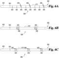
- guide member 600 is illustrated having a first guide body portion 610 with an echogenic marker 606 embodied as a marker pattern with one or more longitudinally spaced echogenic marker regions 605.
- Marker regions 605 include one or more echogenic marker elements 608.
- first guide body portion 610 is joined to a second guide body portion 603 at joint 604.
- marker elements 608 may be separated from one another by discontinuities in the echogenic material or structure.
- Each of the individual marker elements 608 are constructed as discussed above with respect to marker elements 508 and markers 129.
- Each individual echogenic marker element 608 in Fig. 6A can therefore be thought of as an echogenic "dot”.
- each individual echogenic marker element 608 is an echogenic ring, or individual dots arranged annularly in one or more ring patterns within each marker region 605.
- Figs. 7A, 7B, and 7C also illustrate various arrangements of discrete echogenic markers 708 spaced along a first guide body portion 710 of a guide member 700 also having a second guide body portion 703 joined to the first guide body portion 710 at joint 704.
- multiple echogenic markers 708 are illustrated as individual echogenic "dots" as discussed above.
- the echogenic markers 708 are positioned in a helical marker pattern rather than in a straight line shown in Fig. 7A .
- each echogenic marker 708 is a configured as a band disposed around at least a portion of the perimeter or circumference of guide member 700.
- each "dot" or ring illustrated in Fig. 7A through 7C indicates an individual echogenic marker 708 formed from an echogenic substance or structure as described above such as a ring of metal, solid bead of metal, a bubble of air, metal flake, or void filled with a gas, a vacuum, or other echogenic substance.
Landscapes
- Health & Medical Sciences (AREA)
- Life Sciences & Earth Sciences (AREA)
- General Health & Medical Sciences (AREA)
- Heart & Thoracic Surgery (AREA)
- Biophysics (AREA)
- Veterinary Medicine (AREA)
- Public Health (AREA)
- Animal Behavior & Ethology (AREA)
- Engineering & Computer Science (AREA)
- Biomedical Technology (AREA)
- Medical Informatics (AREA)
- Physics & Mathematics (AREA)
- Molecular Biology (AREA)
- Surgery (AREA)
- Radiology & Medical Imaging (AREA)
- Pathology (AREA)
- Nuclear Medicine, Radiotherapy & Molecular Imaging (AREA)
- Vascular Medicine (AREA)
- Hematology (AREA)
- Pulmonology (AREA)
- Anesthesiology (AREA)
- Ultra Sonic Daignosis Equipment (AREA)
Description
- This application claims the benefit of priority of
United States Patent Application Serial No. 61/989,679 filed May 7, 2014 - The present invention relates generally to medical devices and procedures, and in particular aspects, to vascular guidewires and combinations thereof with other vascular devices, such as catheters, that can be beneficially used in animal and human patients when conducting procedures that employ intravascular ultrasound (IVUS) for imaging.
- Guidewires useful for intravascular procedures can be constructed using various materials and techniques. For example, guidewires can be constructed of segments of metallic wire formed into coils or strands, or both. Wire guides may also be coated with one or more of a wide range of coatings, such as for example, Polytetrafluoroethylene (PTFE) for reduced friction, or an anticoagulation agent like Heparin to reduce blood clotting.
- However, metal wire guides are highly reflective to ultrasound because the characteristic acoustic impedance of metallic substances causes substantially all of the sound waves to reflect off the device rather than passing through. Therefore, when metal guidewires are inserted into a patient and imaged using ultrasound imaging devices, various artifacts are routinely observed which can obscure important imaging features. For example, when a metallic guidewire is in use, a bright dot may be observed with a large shadow behind the wire.
- These artifacts may be especially severe in IVUS imaging. Due to space, size, and cost (i.e. one time use) limitations, IVUS transducers may have lower overall performance as compared to conventional transcutaneous transducers. Therefore, artifacts may be more pronounced further degrading image quality. The artifacts may be especially severe if the wire is close to the IVUS transducer further reducing opportunities to obtain usable, and perhaps critically important, clinical information from the ultrasound image.
- Reference is directed to
US 2009/0131910 andUS 2008/0154136 which disclose a catheter for use in a patient's body lumen, having a shaft section configured to minimize ultrasonic image artifacts and to produce its image at a wide range of imaging angles, preferably with an intensity not substantially different than surrounding tissue of the body lumen under ultrasound visualization. To do this, the shaft section has inner and outer layers designed to produce echoes in the patient's body of approximately equal amplitude which destructively interfere. - The embodiments disclosed are directed toward guide members, such as guidewires and wire guides having similar function and purpose to those discussed above that are useable in conjunction with intravascular ultrasound procedures but which reduce or eliminate visual artifacts caused by metallic or other echogenic materials. Also included are modes of construction as well as examples of techniques and descriptions of their use.
- Embodiments described include guidewires that are at least partially echolucent presenting reduced visual interference in an ultrasound image when the echolucent portion is present within the imageable region. Ultrasonic waves preferably resonate in a frequency range as low as 20khz or as high as 4Ghz, with lower or higher frequencies possible as well depending on factors such as the imaging device used and the clinical objectives to name a few. Sound waves at any frequency cause the molecules of a physical substance they pass through (a "medium") to vibrate. The density and the speed at which sound travels in the medium dictates how easily sound energy can pass through the medium. As sound waves pass through one medium to another different medium, the energy waves can change velocity causing some of the sound energy to be reflected off the new medium and some to pass through at a new velocity.
- For example in a clinical setting, as sound waves move away from an ultrasonic transducer and through a human or animal, they may encounter several substances along the way such as muscle, bone, various liquids, air or other gases, and the like. Various clinical instruments and apparatus (such as a guidewire) may also be in the path of these waves. As the sound waves travel from one medium to another, such as from human tissue, through bodily fluids, through a guidewire, perhaps through bodily fluids again, and into the same or other human tissue behind the guidewire, the sound waves change speed at the interfaces between the different media. This speed change causes some of the sound energy to be reflected back toward the transducer, while some of the sound energy continues on away from the transducer. Generally speaking, as more sound energy is reflected back to the transducer, the reflecting medium generally appears more distinctly in the resulting ultrasound image. Therefore, materials that are "echolucent" appear less distinctly because they allow sound waves to travel through them causing fewer echoes. Materials that are "echogenic" allow fewer sound waves to travel through and cause more sound energy to be reflected. For example, as disclosed below, materials reflecting about the same amount of sound energy as soft tissue and fat result in few if any echoes being returned from these materials when they are used in a medical apparatus such as a guidewire inserted in the body adjacent to soft tissue and fat.
- Different materials can be chosen to adjust the "echolucence" of a device because doing so changes the characteristic acoustic impedance of the device. The characteristic acoustic impedance of a material or medium is an inherent property of that particular medium and is the product of the density of the medium and the speed of sound in the medium when no sound waves are traveling in it. Measured in Rayleigh (Rayl), 1 Rayl equals 1 newton-second per cubic meter or 1 kg/s-m2. Therefore the materials used in the construction of a guidewire or other similar apparatus may be varied to adjust the characteristic acoustic impedance of the material, thereby changing the ratio of sound energy passing through the material to the sound energy reflected by it. This can result in a guidewire or similar apparatus creating few if any resulting echoes under ultrasonic imaging thus reducing the visibility of the device. Reduced visibility caused by using echolucent materials makes it possible to image structures behind the guidewire (that is structures opposite the guidewire from the transducer) because sound energy can reach the more distal media by passing through the guidewire both after leaving the transducer and again on the way back to it.
- Various materials and modes of construction can be used to vary the echolucent properties of a guidewire or other such apparatus as disclosed. In one example, echogenic markers and marker regions are included along with the echolucent regions of the guide members. These echogenic markers may, for example, be constructed from a medium having a characteristic acoustic impedance that differs widely from that of human or animal flesh. For instance, the characteristic acoustic impedance of air at about room temperature is about 415 Rayl while the characteristic acoustic impedance of certain human or animal tissue can be in the range between about 1.5 to about 1.7 MRayl (or million Rayl) - over 3800 times higher. Thus, examples of guidewires with echogenic markers include guidewires made at least partially of materials having a characteristic acoustic impedance that is approximately equal to that of human flesh where the material also encapsulates or includes one or more voids containing air. Under ultrasound imaging, the voids (i.e. "bubbles", or "markers") enclosed in the material are more visible in the resulting image than the surrounding material which can be substantially invisible, or at least its visibility can be substantially reduced.
- Also disclosed are other materials, forms, and configurations besides air bubbles that could be used as markers, this being merely one example. Metallic flakes, elongated strips, beads, and other arrangements of marking elements or groups of elements embedded within or coupled to an echolucent guide member, or guide member portion, can therefore assist clinicians in tracking and positioning the guide members during imaging while minimizing unwanted artifacts. Also disclosed are embodiments of guide members used in conjunction with two dimensional and three dimensional intravascular ultrasound imaging devices.
-
-
Fig. 1 is a longitudinal cross-sectional view of the distal end of one example of a guide member and other apparatuses useful in intravascular ultrasound procedures. -
Fig. 2 is a perspective partial cut-away view of the devices fromFig. 1 introduced within a vascular lumen and connected to imaging equipment. -
Fig. 3 is a longitudinal cross-sectional view of the distal end of the guide member fromFig. 1 in use with still other apparatuses useful in intravascular ultrasound procedures. -
Fig. 4 is a perspective partial cut-away view of the devices fromFigs. 1 and3 introduced within a vascular lumen and connected to the imaging equipment ofFig. 1 . -
Fig. 5A - 7C are perspective views of other embodiments of the guide member shown inFigs. 1 - 4 . - For the purpose of promoting an understanding of the principles of the invention, reference will now be made to embodiments, some of which are illustrated in the drawings, and specific language will be used to describe the same. It will nevertheless be understood that no limitation of the scope of the invention is thereby intended. Any alterations and further modifications in the described embodiments, and any further applications of the principles of the invention as described herein are contemplated as would normally occur to one skilled in the art to which the invention relates.
- Illustrated in
Fig. 1 at 100 is one embodiment of aguide member 133 along with other associated apparatuses useful for intravascular ultrasound procedures in an animal or human patient.Guide member 133 is shown having a segmented arrangement of individual portions or segments joined together, these portions themselves may then also include other portions or segments as well depending on the materials used, the mode of construction, and the intended use. In the embodiment shown inFig. 1 , a firstguide body portion 130 forming the distal end ofguide member 133 is coupled to a secondguide body portion 103, with the two segments joined to one another atjoint 113. Firstguide body portion 130 has one or more longitudinally spaced discreteechogenic markers 129 interspersed along its length which are operable to appear during ultrasonic imaging procedures.Guide member 133 may be positioned within afirst lumen 117 and can extend beyonddistal end 127 of anelongate carrier body 110.Elongate carrier body 110 can serve various functions such as maintaining an association betweenguide member 133 and anintravascular ultrasound probe 107 positioned within asecond lumen 124. By maintaining this association,guide member 133 can aid in maneuveringintravascular ultrasound probe 107 into position within the patient's body. -
Intravascular ultrasound probe 107 positioned withinsecond lumen 124 has at its distal end anultrasonic transducer 120 which is operable to emit ultrasonic energy and detect the reflected energy for the purpose of performing ultrasonic imaging of interior spaces of a patient's anatomy such as organs, blood vessels, and the like.Ultrasonic transducer 120 is preferably positioned distal to joint 113 so that ultrasonic energy emitted fromultrasonic transducer 120 passes throughcarrier body 110 and firstguide body portion 130 but not through secondguide body portion 103. -
Elongate carrier body 110 can be constructed of any material suitable for intravascular introduction and navigation through blood vessels, organs, and other structures within a patient's body. Suitable materials include, but are not limited to, polyurethane, nylon, polyethylene, and silicone. Preferablyelongate carrier body 110 includes echo lucent materials to reduce or substantially eliminate sound energy reflected by the echolucent portion ofcarrier body 110. By including echo lucent material inelongate carrier body 110 in those regions where ultrasonic energy resonates fromtransducer 120, ultrasonic waves can pass substantially unimpeded throughcarrier body 110 allowing the tissue surroundingcarrier body 110 to be imaged. - One embodiment of
elongate carrier body 110 is a catheter having multiple lumens extending through some or all of the length of the catheter and exiting at or near the catheter's distal end. In this embodiment, the catheter acts to keepguide member 133 andintravascular ultrasound probe 107 properly positioned relative to one another such thatguide member 133 can be used to help advanceelongate carrier body 110.Elongate carrier body 110 can then be useful for properly advancingintravascular ultrasound probe 107 to its intended region within the body. Other embodiments ofelongate carrier body 110 include catheters having anintravascular ultrasound probe 107 embedded in, or otherwise coupled with, the catheter itself. -
Fig. 1 illustrates a firstguide body portion 130 that includes an echolucent material. An echolucent material includes any material having a characteristic acoustic impedance substantially similar or about equal to the characteristic acoustic impedance of the surrounding material (e.g. bone, blood, muscle, bodily fluids, or other human or animal anatomical features of interest). Thus as sound waves pass through from the surrounding media and through firstguide body portion 130, the change in speed of the high frequency sound waves is minimized resulting in fewer echoes being returned totransducer 120 fromguide body portion 130. The results include ultrasound images whereguide body portion 130 may be substantially or completely invisible. This allows the surrounding tissue or other anatomical structures of interest to be imaged rather than guidebody portion 130. - In one example, the echolucent material in first
guide body portion 130 may have a characteristic acoustic impedance of between about 1.5 MRayl and about 2.2 MRayl, which is approximately the range of characteristic acoustic impedances for many types of human or animal tissue. Examples of such echolucent materials include Polyethylene (PE), Polymethylpentene, and Ethyl Vinil Acetate. In another example, the echolucent material in firstguide body portion 130 may have a characteristic acoustic impedance of between about 1 MRayl and about 5 MRayl, although such a material may cause reduced performance makingguide body portion 130 more visible during ultrasonic imaging procedures. Examples of such materials include Acrylic, Polyvinyl Chloride (PVC), Polycarbonate, Nylon, Polystyrene, Vinyl, and Acrylonitrile Butadiene Styrene (ABS). Firstguide body portion 130 may, for example, include a polymeric material having a density in the range of 0.5 grams/cc to 3.5 grams/cc. In another embodiment, firstguide body portion 130 includes polyethylene or another polymeric material having a density in the range of about 0.8 grams/cc to about 1.1 grams/cc. - In other embodiments, first
guide body portion 130 may include other echogenic structures or substances to modify the number and strength of reflected sound waves. Making a firstguide body portion 130 disappear entirely from the resulting image may be undesirable and may result in a substantial reduction or complete loss of positional feedback. As a result, the clinician may, in such situations, be unable to properly maneuver and position firstguide body portion 130 during the ultrasonic imaging procedure. - Providing positional feedback using the ultrasonic imaging system may be achieved in various ways such as through the use of echogenic markers or marker regions as discussed below. However, it may also be advantageous to optionally include an echo-opacifier into the polymeric material used to construct first
guide body portion 130 to precisely control its characteristic acoustic impedance. Examples of echo-opacifiers that might be used include tungsten nanoparticles, glass or ceramic beads, or gas filled voids or other similar structures or materials included withguide body portion 130. By varying the concentration, placement, size and other aspects of the additives or structures, the acoustic impedance and corresponding echogenicity and echolucence may be modified to control the resulting appearance of firstguide body portion 130 in an ultrasound image. - The echolucence may also be reduced and echogenicity increased by using materials with characteristic acoustic impedances that differ from the characteristic acoustic impedance of the human or animal tissue in the surrounding region. For example, constructing a
guide body portion 130 from PVC, which has a characteristic acoustic impedance of about 3 MRayl, can provide additional visibility of firstguide body portion 130 for the clinician while still allowing some of the sound waves to pass through making it still possible to image the area behindguide body portion 130. - In other embodiments, other materials or structures may also be included in first
guide body portion 130 to modify its visibility with respect to other types of imaging technologies such as to make firstguide body portion 130 partially or completely radio opaque. Such an embodiment may be useful where two different imaging technologies (e.g. ultrasonography and radiography) are used during the same procedure. For example, firstguide body portion 130 may be constructed of Polyethylene (which has a characteristic acoustic impedance of about 1.73 MRayl) that also includes Barium sulfate or other similar radio-opacifier. The resulting guide wire may therefore be echolucent returning very few echoes totransducer 120 presenting a reduced or minimally visible ultrasound image while also being visible during X-ray imaging. - Tracking the position of first
guide body portion 130 may also be achieved by including one or moreechogenic markers 129 spaced longitudinally along the long axis of firstguide body portion 130. AlthoughFig. 1 illustrates a firstguide body portion 130 having threeechogenic markers 129, the precise number ofechogenic markers 129 shown inFig. 1 is only illustrative. In some embodiments only oneechogenic marker 129 may appear while in other embodiments numerous markers, or groups of markers, may be included. (SeeFigs. 5A through 7C and the accompanying description below for examples.) -
Echogenic markers 129 include individual flakes of metal of the proper size and shape affixed to or embedded withinguide member 133, metal beads or plugs embedded withinguide member 133, metal strands or fibers adhered to the external surface ofguide member 133, or metal strands or fibers embedded within the interior ofguide member 133. Various metals might be used as an echogenic material forechogenic markers 129. For example, substances such as stainless steel or a nickel and titanium alloy like nitinol might be formed into flakes, strands, fibers, or other forms and embedded, attached, adhered, or otherwise coupled and included withguide member 133 to formechogenic markers 129. - Other embodiments of
echogenic markers 129 include a firstguide body portion 130 ofguide member 133 where eachechogenic marker 129 includes one or more echogenic structures such as one or more empty or gas filled spaces or "bubbles" at the proper positions along the length ofguide member 133. These bubbles may be of various sizes such as large and individually positioned bubbles where each individual bubble serves as anechogenic marker 129, or individually small bubbles arranged together to form rings, lines, or other shapes serving as echogenic markers 129 (SeeFigs. 5C - 7B ). The bubbles themselves may define an empty space containing a near vacuum, or be filled with a small quantity of gas, or contain any type of matter having a characteristic acoustic impedance that substantially differs from the surrounding tissue. - Other embodiments of
guide member 133 are envisioned as well. For example, it is envisioned that in another embodiment ofguide member 133 no joint 113 exists. In this embodiment, firstguide body portion 130 is a single first guide body segment formed of echolucent material and has associated with it at least oneechogenic marker 129. In this embodiment, no concern need be given to the positioning ofguide member 133 relative to ultrasonic transducer 120 (discussed in greater detail below with regard toFigs. 2 and4 ) because all ofguide member 133 is echolucent and no secondguide body portion 103 is included. One example of such aguide member 133 is a guidewire for use in an intravascular ultrasound procedure formed from an echolucent material with one or more echogenic markers associated with the guidewire, preferably at or near its distal end. One example of such a guidewire is a polyethylene guidewire having a single echogenic marker formed from a nitinol bead embedded within the guidewire near its distal end. - In the embodiment illustrated in
Fig. 1 , secondguide body portion 103 may be formed from an echogenic material, or other similar material. In one preferred embodiment, secondguide body portion 103 includes a metal or metallic substance such as a material containing a combination of polymeric (or other nonmetallic) and metallic fibers. Examples of aguide member 133 having echogenic properties include a guidewire constructed of strands or coils of stainless steel or nitinol, or other similarly echogenic material, having a segment coupled to the distal end constructed from Polyethylene or other similar echolucent material. - Shown in
Fig. 2 is an illustration of the apparatus illustrated inFig. 1 in use during a procedure such as an intravascular procedure to image internal areas of a human or animal patient's body.Elongate carrier body 110 is shown inFig. 2 introduced into avascular vessel 200 having avascular lumen 204 with avascular wall 206 and avascular blockage 214.Guide member 133 is shown projecting from the distal end ofelongate carrier body 110 beyondintravascular ultrasound probe 107. Asultrasonic transducer 120 ofintravascular ultrasound probe 107 is energized,ultrasonic energy waves 219 begin to radiate outwardly fromintravascular ultrasound probe 107 throughelongate carrier body 110 into and through animageable region 212 which is external to elongatecarrier body 110 and extends through the contents ofvascular lumen 204, throughvascular wall 206 and perhaps beyond. Depending on the particular implementation ofintravascular ultrasound probe 107 in use, the imageable region may at any time include only a partialimageable region 211 of the totalimageable region 212. Therefore, some embodiments ofintravascular ultrasound probe 107 must be rotated repeatedly to obtain updated views of the entireimageable region 212. In one embodiment ofintravascular ultrasound probe 107, updated views of theimageable region 212 are generated automatically by anultrasonic transducer 120 having an array of one or more radiating elements configured to electronically sweepimageable region 212 without rotatingultrasonic transducer 120. In another embodiment ofintravascular ultrasound probe 107, updated image data fromimageable region 212 is generated by manually rotatingultrasonic transducer 120 such as by the clinician applying rotational torque onultrasound probe 107, or by the use of a rotational device such as an electric motor coupled toultrasound probe 107. - Regardless of how much or little of
imageable region 212 is scanned or imaged at any given time, in this embodiment ofintravascular ultrasound probe 107, the imageable region is a substantially two-dimensional cross-sectional slice which can include thevascular lumen 204 and its contents,vascular wall 206, as well as any abnormalities invascular wall 206 such asvascular blockage 214. The cross-sectional slice is imaged at the approximate location ofultrasonic transducer 120 as indicated by the location ofimageable region 212. It should be noted that althoughFig. 2 indicates an apparent maximum extent of theimageable region 212, no assumption should be made from the illustration as to whether such a maximum range exists, nor how far it extends. Many factors determine the sensory capabilities of an ultrasonic imaging probe in general. Among them are the unique attributes of a particular patient, the particular location within the body relative to various organs and structures, the power and frequency of the emitted energy, as well as various other operational settings of the particular embodiment ofultrasonic transducer 120 in use. Thus no particular assumption should be made as to the degree to whichimageable region 212 extends beyond the walls ofelongate carrier body 110. - The result of penetrating
imageable region 212 withultrasonic energy waves 219 and detecting the return echoes may include image data indicating various information such as the extent to whichvascular blockage 214 extends intovascular lumen 204, and the type of materialvascular blockage 214 is composed of, to name a few examples. In order to collect this information,elongate carrier body 110 is coupled to an imagedata interface device 233 through atransducer link 223 such as a data cable or wireless data link that is operable to transmit data fromtransducer 120 todata interface device 233. Data interface device is also coupled to imagedata display device 227 by a connectingmember 229 such as a data cable, wireless data link, or other similar device able to transmit data todata display device 227. Return echoes from objects within theimageable region 212 are converted to a data stream by imagedata interface device 233 and the data is then passed to imagedata display device 227 where the data is processed intoimage data 225 and displayed as an image ofimageable area 212 for the clinician to view, review, save for the patient to view later, archive in medical records, or use for other purposes. - In some embodiments, image
data display device 227 is a general purpose computer capable of operating specialized software able to capture data received through connectingmember 229 from imagedata display device 227, process the data into one or more images, and display thisimage data 225. In other embodiments, imagedata display device 227 is a specialty built computer designed and built for only the purpose of capturing image data from connectingmember 229 and processing the data intoimage data 225. In either case,image data 225 is processed into any of various visual representations such as still frames containing individual snapshots ofimageable region 212, or as a stream ofimage data 225 appearing on imagedata display device 227 as a moving image. In the case of a moving image,image data 225 is preferably refreshed with new data fromimageable region 212 at a rate of greater than 15 frames per second, more preferably greater than 20 frames per second, and most preferably 30 frames per second or more. - The use of
guide member 133 is shown inFig. 2 whereguide member 133 has been introduced into the body along withelongate carrier body 110 andintravascular ultrasound probe 107. It is commonly the case that guidemember 133 is introduced into the body first, followed byelongate carrier body 110, possibly then followed byintravascular ultrasound probe 107. It is also common forguide member 133 to be advanced some distance through the body ahead ofelongate carrier body 110 before the elongate carrier body andintravascular ultrasound probe 107 are then advanced together as well. The sequence of advancingguide member 133 followed byelongate carrier body 110 is then repeated until the area of interest is reached, or until the procedure is complete for in some cases the purpose of advancingintravascular ultrasound probe 107 is to obtain image data throughout the journey. Navigation ofguide member 133 throughout this process is frequently aided by other imaging techniques such as fluoroscopy, MRI imaging, and the like. Upon arriving at the area to be imaged, or possibly in some cases throughout the journey,guide member 133 extends beyond distal end ofelongate carrier body 110 as shown inFig. 2 .Intravascular ultrasound probe 107 can then be activated (if it is not already active) causingimage data 225 to begin appearing on imagedata display device 227. - As can be seen in
Fig. 2 , joint 113 can be positioned proximal toultrasonic transducer 120 and is therefore proximal toimageable region 212. By this relative positioning ofguide member 133 andintravascular ultrasound probe 107, firstguide body portion 130 comprising an echolucent material is the only portion ofguide member 133 withinimageable region 212. As a result, ultrasonic energy emitted byultrasonic transducer 120 passes through firstguide body portion 130 rather than being reflected by it, and therefore firstguide body portion 130 does not substantially interfere withimage data 225. This result is preferable insofar as it avoids extraneous information appearing withinimage data 225 that may obscure more important information, make important information more difficult to discern, or otherwise interfere withimage data 225. However, ifguide member 133 is positioned such that joint 113 is distal toultrasonic transducer 120, secondguide body portion 103 will be positioned withinimageable region 212. Extraneous information will then begin to appear inimage data 225 because secondguide body portion 103 is composed of an echogenic material that will not allow some or all of the ultrasonic energy emitted byultrasonic transducer 120 to pass through it thus causing interference to appear within withimage data 225. - In some cases it may be preferable for the clinician to have a visual cue appearing within
image data 225 indicating the location of the echolucent portion ofguide member 133 withinvascular lumen 204. This potential need is facilitated by a plurality of longitudinally spacedechogenic markers 129 which may also be implemented as marker regions having groups of markings arranged in various patterns such as a helix, lines, stripes, dots and the like (examples of various embodiments of echogenic markings are shown inFigs. 5A through 7C ).Ultrasonic energy 219 passes through firstguide body portion 130 but is reflected back to intravascularultrasonic transducer 120 by anyechogenic markers 129 in the path of emittedultrasonic energy 219. Because of their small size relative to guidemember 133,echogenic markers 129 appear inimage data 225, and therefore indicate the position of firstguide body portion 130 without causing substantial visual interference.Echogenic markers 129 therefore aid the clinician in maneuveringguide member 133 while still maintaining visual cues withinimage data 225 that do not cause substantial visual interference. - Depending on the type of ultrasonic transducer used, the image data collected may be a series of two dimensional cross-sectional slices captured at various points within the patient's body and then displayed. In other embodiments, the ultrasonic transducer may be capable of generating image data which includes a three dimensional or volumetric representation of the area of interest. An example of a device having these capabilities is illustrated in
Fig. 3 and shown in operation inFig. 4 and described below. - Illustrated in
Fig. 3 at 300 is an example of use theguide member 133 illustrated inFig. 1 in conjunction with a forward-looking ultrasound transducer.Guide member 133 extends beyond the distal end of anelongate carrier body 304 having aninternal lumen 311 and anintravascular ultrasound probe 320 atdistal end 327.Intravascular ultrasound probe 320 includes a forward-lookingtransducer array 325 arranged annularly arounddistal end 327 ofelongate carrier body 304.Guide member 133 extends past forward-lookingtransducer array 325 thereby allowing ultrasonic energy emanating from forward-lookingtransducer array 325 to pass through and around firstguide body portion 130. As inFigs. 1 and 2 , joint 113 appears proximally tointravascular ultrasound probe 320 such that secondguide body portion 103 composed of echogenic material is proximal to forward-lookingtransducer array 325 while firstguide body portion 130 composed primarily of echolucent material passes throughdistal end 327 and is distal to forward-lookingtransducer array 325. Rather than an ultrasonic transducer that radiates ultrasonic energy laterally through the side walls of the elongate carrier body 304 (as inFigs. 1 and 2 ), an array of multiple transducers are arranged to emit ultrasonic energy forward oftransducer array 325 toward the region distal todistal end 327. - One embodiment of
intravascular ultrasound probe 320 contains an array of Capacitive Micromachined Ultrasonic Transducers (CMUT) arranged in a forward-lookingtransducer array 325 such that ultrasonic energy is directed longitudinally ahead oftransducer array 325 andcarrier body 304. Ultrasonic energy is emitted and detected by elements in thearray 325 which are controlled byintegrated circuits 317. Other types of transducers and transducer arrays may be used as well such as piezoelectric transducers. In this example ofelongate carrier body 304, the CMUT transducer array is positioned at the distal end of a single lumen catheter. Other configurations are also envisioned such as multi-lumen catheters, or a forward-looking transducer array positioned next to the distal end rather than annularly around it. -
Fig. 4 illustrates how the devices shown inFig. 3 could be used in an imaging procedure such as intravascular imaging of a partially blocked internal lumen in a patient such as a vascular vessel. Ablood vessel 400 appears inFig. 4 which is similar to the vessel appearing inFig. 2 .Blood vessel 400 has avascular lumen 404, within which has been introducedelongate carrier body 304 having anintravascular ultrasound probe 320 coupled to its distal end.Intravascular ultrasound probe 320 includes a forward-lookingtransducer array 325.Ultrasonic waves 419 are generated by forward-lookingtransducer array 325 creating a three-dimensional imageable region 411 into which is positionedguide member 133. Parts ofvascular wall 406 andvascular blockage 414 are also withinimageable region 411 as shown inFig. 4 given their relative position totransducer array 325. - As forward-looking
transducer array 325 is activated,ultrasonic energy waves 419 begin to radiate fromintravascular ultrasound probe 320 beyonddistal end 327 ofelongate carrier body 304 and into and throughimageable region 411.Imageable region 411 is external to elongatecarrier body 304 and includes the contents ofvascular lumen 404,vascular wall 406,vascular blockage 414, and possibly the contents of structures and tissues outsidevascular vessel 400. The behavior of each individual transducer within the forward-lookingtransducer array 325 is coordinated byintegrated circuits 317 so thatintravascular ultrasound probe 320 operates to image all ofimageable area 411 as a three-dimensional region capturing properties of the structures within the region such as volumes, densities, rates of flow of fluids throughvascular lumen 404, shapes, sizes, lengths, and other properties of objects found within the region that may be determined. It should be noted that althoughFig. 4 indicates an apparent maximum extent of theimageable region 411, no assumption should be made from the illustration as to whether such a maximum range exists, nor to what extent it reaches. Many factors determine the sensory capabilities of an ultrasonic imaging probe in general. Among them are the unique attributes of a particular patient, the particular location within the body relative to various organs and structures, as well as the power and construction of the forward-lookingtransducer array 325. Thus no particular assumption should be made as to the degree to whichimageable region 411 extends beyonddistal end 327. - The result of penetrating
imageable region 411 with ultrasonic energy and sensing the return echoes is three-dimensional image data 425 indicating various information such as the extent to whichvascular blockage 414 extends intovascular lumen 404, the type and density of the materialvascular blockage 414 is made of, and various other related information. In order to collect this information,elongate carrier body 110 is coupled to an imagedata interface device 233 through atransducer link 223 as described above. Thedata interface device 233 is in turn coupled to imagedata display device 227 by connectingmember 229, also as described above. Return echoes from withinimageable region 411 are converted to a data stream by imagedata interface device 233 and the data is then passed to imagedata display device 227. The data is then processed into three-dimensional image data 425 and displayed as a three-dimensional image ofimageable area 411, or possibly also viewed as a collection of two-dimensional images, or "slices", extracted from the three-dimensional image data 425. The clinician may then view, review, or save the images or the data for the patient to view later, archive in medical records, or use for other purposes. - During the use of
guide member 133 shown inFig. 4 , the clinician may introduceelongate carrier body 304 into the body at an appropriate point by various methods depending on the procedure required. The clinician may also introduceguide member 133 throughfirst lumen 311 at the same time, or at another time as well. The precise order of activities used to introduceguide member 133 is unimportant to the use of the system for collecting information.Elongate carrier body 304 is advanced through the body, preferably through a vascular lumen such as a blood vessel, to the area of the body to be imaged byintravascular ultrasound probe 320. This navigation is facilitated byguide member 133 which is often introduced well ahead ofelongate carrier body 320 for the purpose of guiding it through the body. The navigation ofguide member 133 may also be aided through imaging performed by other means such as by fluoroscopy, MRI imaging, and the like. In many cases it may be advantageous to operateintravascular ultrasound probe 320 to obtain image data as theelongate carrier body 304 is advanced as well. -
Fig. 4 illustrates the operation ofintravascular ultrasound probe 320 in conjunction withguide member 133. It can be seen inFig. 4 (as inFig. 2 ) that joint 113 is preferably positioned proximally toultrasonic transducer 320 and is therefore proximal toimageable region 411. By this relative positioning ofguide member 133 andintravascular ultrasound probe 320, firstguide body portion 130 including echolucent material is the only portion ofguide member 133 withinimageable region 411. As a result,ultrasonic energy 419 emitted from forward-lookingtransducer array 325 passes primarily through firstguide body portion 130 rather than being substantially reflected by it and therefore firstguide body portion 130 does not substantially interfere withimage data 425. This result is preferable insofar as it avoids excessive extraneous information appearing withinimage data 425 that may otherwise obscure important information or make important information more difficult to discern. However, ifguide member 133 is positioned with joint 113 distal to forward-lookingtransducer array 325, extraneous information, "noise," "shadows," or other interference may begin to appear inimage data 425 if secondguide body portion 103 is composed of echogenic material that blocks the passage ofultrasonic energy 419 throughguide member 133 causing it to appear in, or interfere with, resultingimage data 425. - As discussed above with regard to
Fig. 2 , in some cases it may be preferable for the clinician to maintain visual cues withinimage data 425 indicating the location of the echolucent portion ofguide member 133 withinvascular lumen 404. This may be especially useful where the clinician is operating an automated imaging system that may rely on the echogenic markers in order to automatically position intravascular ultrasoundultrasonic probe 320. Therefore, as noted above, at least one, and possibly more than one, longitudinally spacedechogenic marker 129 is provided as part of firstguide body portion 130 ofguide member 133.Echogenic markers 129 may be individual markings or marker regions having groups of markings arranged in various patterns such as a helix, lines, stripes, dots and the like (examples of various embodiments of echogenic markers and marker regions are shown inFigs. 5A through 7C ). Some or all ofultrasonic energy 419 can then pass through the rest ofguide member 133 with small amounts being reflected back toultrasonic transducer array 325 byechogenic markers 129 or optionally byguide member 133 as well depending on its construction. Because of their small size relative to firstguide body portion 130,echogenic markers 129 appear inimage data 425 and therefore indicate the position of firstguide body portion 130 but without causing substantial visual interference.Echogenic markers 129 thereby aid the clinician in maneuveringguide member 133 throughvascular lumen 404 by maintaining visual cues within three-dimensional image data 425. - Various types of visual cues may be required depending on a number of factors such as whether the imageable region is two-dimensional or three-dimensional, the location to be imaged within the body, the type of structures to be imaged, and others. Illustrated in
Figs. 5A through 7C are various examples of guide members similar to guidemember 133 having various arrangements of echogenic markers and marker regions. In each of these embodiments described in the followingFigs. 5A through 7C , as withechogenic markers 129 shown inFigs. 1 through 4 above, echogenic markers have various modes of construction. For example an echogenic marker that appears as a ring (such asechogenic marker 129 inFig. 1 through Fig. 4 ) may be created by adhering a narrow band of echogenic material such as metal, or other acoustically reflective material, to the exterior surface of the guide member (such asguide member 133 inFig. 1 ). Likewise, a similar effect may be achieved by embedding a narrow band of echogenic material within or beneath the surface of the guide member. Other embodiments are also envisioned such as a void within the guide member filled with a vacuum, or a gas such as nitrogen, air, or other gas, or a small piece of echogenic material such as a metal bead, metal flakes, or other echogenic material within the body of the guide member. These various modes of construction can be used together as well in various combinations to create the echogenic markers described. - Illustrated in
Figs. 5A, 5B, and 5C , are examples of aguide member 500 having a firstguide body portion 510, joined to a secondguide body portion 503 at joint 504. A continuous longitudinally extendingechogenic marker 506 appears as well. InFig. 5A ,echogenic marker 506 appears as a single continuous unbroken ribbon or band extending along firstguide body portion 510 substantially parallel to the longitudinal axis of firstguide body portion 510. As described above,echogenic marker 506 may be created by attaching echogenic material to the exterior ofguide member 500, by embedding echogenic material within theguide member 500, or by manufacturingguide member 500 with echogenic structures or materials within firstguide body portion 510. Other techniques may be used as well for causingechogenic marker 506 to appear during imaging as well. InFig. 5B ,echogenic marker 506 is a single continuous longitudinally extending echogenic marker defining a helical pattern. A similarechogenic marker 506 appears inFig. 5C comprising a continuous longitudinally extendingechogenic marker 506 here embodied as a marker pattern having a pattern ofechogenic marker elements 508 separated by discontinuities in the marker material or structure. In this embodiment, each individualechogenic marker element 508 is part of a singleechogenic marker 506. Each "dot" (marker element 508) inFig. 5C may be an individual metal flake, metal bead, gas bubble, or other echogenic material or structure as described above with respect tomarkers 129. - In
Fig. 6A, 6B, and 6C ,guide member 600 is illustrated having a firstguide body portion 610 with anechogenic marker 606 embodied as a marker pattern with one or more longitudinally spacedechogenic marker regions 605.Marker regions 605 include one or moreechogenic marker elements 608. Similar to previously mentioned embodiments, firstguide body portion 610 is joined to a secondguide body portion 603 at joint 604. As illustrated,marker elements 608 may be separated from one another by discontinuities in the echogenic material or structure. Each of theindividual marker elements 608 are constructed as discussed above with respect tomarker elements 508 andmarkers 129. Each individualechogenic marker element 608 inFig. 6A can therefore be thought of as an echogenic "dot". InFig. 6B and 6C , each individualechogenic marker element 608 is an echogenic ring, or individual dots arranged annularly in one or more ring patterns within eachmarker region 605. -
Figs. 7A, 7B, and 7C also illustrate various arrangements of discreteechogenic markers 708 spaced along a firstguide body portion 710 of aguide member 700 also having a secondguide body portion 703 joined to the firstguide body portion 710 at joint 704. InFig. 7A and 7B , multipleechogenic markers 708 are illustrated as individual echogenic "dots" as discussed above. InFig. 7B , theechogenic markers 708 are positioned in a helical marker pattern rather than in a straight line shown inFig. 7A . InFig. 7C , eachechogenic marker 708 is a configured as a band disposed around at least a portion of the perimeter or circumference ofguide member 700. As withFig. 5C , each "dot" or ring illustrated inFig. 7A through 7C indicates an individualechogenic marker 708 formed from an echogenic substance or structure as described above such as a ring of metal, solid bead of metal, a bubble of air, metal flake, or void filled with a gas, a vacuum, or other echogenic substance. - The uses of the terms "a" and "an" and "the" and similar references in the context of describing the invention (especially in the context of the following claims) are to be construed to cover both the singular and the plural, unless otherwise indicated herein or clearly contradicted by context. Recitation of ranges of values herein are merely intended to serve as a shorthand method of referring individually to each separate value falling within the range, unless otherwise indicated herein, and each separate value is incorporated into the specification as if it were individually recited herein. All methods described herein can be performed in any suitable order unless otherwise indicated herein or otherwise clearly contradicted by context. The use of any and all examples, or exemplary language (e.g., "such as") provided herein, is intended merely to better illuminate the invention and does not pose a limitation on the scope of the invention unless otherwise claimed. No language in the specification should be construed as indicating any non-claimed element as essential to the practice of the invention.
- The invention is defined by the appended claims.
Claims (15)
- A guidewire for use in an intravascular ultrasound procedure, comprising:an elongate guide body (133) configured to traverse a vascular vessel, the elongate guide body having at least a first guide body portion (130) including an echolucent material, the echolucent material allowing ultrasonic energy to pass through the first guide body portion rather than being reflected by it; andat least one echogenic marker (129) associated with the first guide body portion;wherein ultrasonic energy is reflected in use by the at least one echogenic marker (129).
- The guidewire of claim 1, wherein the elongate guide body comprises at least two longitudinally-extending guide body portions joined to one another.
- The guidewire of claims 1 or 2, further comprising:a second guide body portion (103) formed of an echogenic material;wherein said elongate guide body (133) includes at least said first guide body portion (130) joined to said second guide body portion (103).
- The guidewire of claims 2 or 3, wherein the first guide body portion (130) includes a polymeric material, and the second guide body portion includes a metal.
- The guidewire of any one of claims 1 through 4, wherein the at least one echogenic marker includes a plurality of longitudinally spaced echogenic marker regions.
- The guidewire of any one of claims 1 through 4, wherein the at least one echogenic marker includes a plurality of discrete echogenic markers or a continuous longitudinally-extending echogenic marker.
- The guidewire of claim 6, wherein the at least one echogenic maker includes said continuous longitudinally-extending echogenic marker, and wherein the longitudinally-extending echogenic marker defines a helical pattern.
- The guidewire of any one of claims 1 through 7, wherein the first guide body portion (130) includes a polymeric material having a density in the range of 0.5 grams/cc to 3.5 grams/cc.
- The guidewire of any one of claims 1 through 8, wherein the first guide body portion (130) includes polyetheylene having a density in the range of about 0.8 grams/cc to about 1.1 grams/cc.
- The guidewire of any one of claims 1 through 9 in combination with an elongate carrier body (110) for intravascular passage, the carrier body defining at least one lumen (117) and carrying at least one intravascular ultrasound probe (107) for generating image data representing an imageable region (212) external of the carrier body; wherein the elongate guide body (130) is receivable through said lumen, and a first guide body portion is capable of passage into said imageable region (212).
- The apparatus of claim 10, wherein the elongate carrier body (110) is a catheter.
- The apparatus of claim 10 or 11, wherein the imageable region (212) is a substantially two-dimensional cross-sectional slice.
- The apparatus of claim 10 or 11 wherein the imageable region is three-dimensional.
- The guidewire of any one of claims 10 to 13, wherein the imageable region (212) includes a region forward of the ultrasound probe (107).
- The apparatus or guidewire of any preceding claim, wherein the echolucent material has an acoustic impedance of between about 1 and 5 M kg s-1 m2 (MRayl) and preferably between about 1.5 and 2.2 M kg s-1 m2 (MRayl).
Applications Claiming Priority (2)
| Application Number | Priority Date | Filing Date | Title |
|---|---|---|---|
| US201461989679P | 2014-05-07 | 2014-05-07 | |
| PCT/US2015/029229 WO2015171602A1 (en) | 2014-05-07 | 2015-05-05 | Guide members and associated apparatuses useful for intravascular ultrasound procedures |
Publications (3)
| Publication Number | Publication Date |
|---|---|
| EP3139839A1 EP3139839A1 (en) | 2017-03-15 |
| EP3139839A4 EP3139839A4 (en) | 2018-01-03 |
| EP3139839B1 true EP3139839B1 (en) | 2024-01-24 |
Family
ID=54366895
Family Applications (1)
| Application Number | Title | Priority Date | Filing Date |
|---|---|---|---|
| EP15789395.9A Active EP3139839B1 (en) | 2014-05-07 | 2015-05-05 | Guide members and associated apparatuses useful for intravascular ultrasound procedures |
Country Status (5)
| Country | Link |
|---|---|
| US (1) | US10485957B2 (en) |
| EP (1) | EP3139839B1 (en) |
| JP (1) | JP6639413B2 (en) |
| AU (1) | AU2015256182B2 (en) |
| WO (1) | WO2015171602A1 (en) |
Families Citing this family (5)
| Publication number | Priority date | Publication date | Assignee | Title |
|---|---|---|---|---|
| US11141565B2 (en) * | 2016-06-23 | 2021-10-12 | Avent, Inc. | Echogenic coil member for a catheter assembly |
| CN211884905U (en) | 2019-08-22 | 2020-11-10 | 贝克顿·迪金森公司 | Balloon dilatation catheter and balloon thereof |
| US20210220620A1 (en) * | 2020-01-22 | 2021-07-22 | Baylis Medical Company Inc. | Medical guidewire assembly having identification device |
| US20210322731A1 (en) * | 2020-01-22 | 2021-10-21 | Baylis Medical Company Inc. | Medical guidewire assembly having identification device |
| CN115484872A (en) * | 2020-03-31 | 2022-12-16 | 泰尔茂株式会社 | Image processing device, image processing system, image display method, and image processing program |
Citations (2)
| Publication number | Priority date | Publication date | Assignee | Title |
|---|---|---|---|---|
| US20100262013A1 (en) * | 2009-04-14 | 2010-10-14 | Smith David M | Universal Multiple Aperture Medical Ultrasound Probe |
| US20140107489A1 (en) * | 2012-10-12 | 2014-04-17 | Muffin Incorporated | Reciprocating internal ultrasound transducer assembly |
Family Cites Families (19)
| Publication number | Priority date | Publication date | Assignee | Title |
|---|---|---|---|---|
| US5596990A (en) * | 1995-06-06 | 1997-01-28 | Yock; Paul | Rotational correlation of intravascular ultrasound image with guide catheter position |
| CA2347391C (en) | 1998-08-19 | 2008-11-18 | Cook Incorporated | Preformed wire guide |
| GB2345543A (en) | 1999-01-06 | 2000-07-12 | Intravascular Res Ltd | Ultrasonic visualisation system with remote components |
| US6475226B1 (en) | 1999-02-03 | 2002-11-05 | Scimed Life Systems, Inc. | Percutaneous bypass apparatus and method |
| ES2220026T3 (en) | 1999-03-29 | 2004-12-01 | William Cook Europe Aps | GUIDE-THREADS. |
| JP3735019B2 (en) * | 2000-08-09 | 2006-01-11 | 英雄 中嶋 | Medical instrument or member capable of ultrasonic diagnosis |
| AU2002245243B2 (en) * | 2001-01-11 | 2007-03-22 | Angiodynamics, Inc. | Bone-treatment instrument and method |
| US7065394B2 (en) * | 2001-12-12 | 2006-06-20 | Medtronic, Inc | Guide catheter |
| AU2003262988A1 (en) * | 2002-08-30 | 2004-03-19 | Inrad, Inc. | Localizing needle with fluid delivery |
| CN100558423C (en) * | 2003-12-18 | 2009-11-11 | 泰尔茂株式会社 | Leading line |
| US8382674B2 (en) * | 2005-12-02 | 2013-02-26 | Abbott Cardiovascular Systems Inc. | Visualization of a catheter viewed under ultrasound imaging |
| US8430863B2 (en) * | 2005-12-02 | 2013-04-30 | Abbott Cardiovascular Systems Inc. | Visualization of a catheter viewed under ultrasound imaging |
| US20110021924A1 (en) * | 2007-02-09 | 2011-01-27 | Shriram Sethuraman | Intravascular photoacoustic and utrasound echo imaging |
| EP2134778A1 (en) * | 2007-03-09 | 2009-12-23 | Dow Global Technologies Inc. | Stress/thermal cracking resistant cable sheath material |
| US8083690B2 (en) * | 2008-09-04 | 2011-12-27 | Vascular Solutions, Inc. | Convertible guidewire system and methods |
| CN104622599B (en) * | 2009-05-18 | 2017-04-12 | 纽姆克斯股份有限公司 | Cross-sectional modification during deployment of an elongate lung volume reduction device |
| AU2011239637B2 (en) | 2010-04-13 | 2014-12-11 | Atricure, Inc. | Methods and devices for pericardial access |
| JP5888740B2 (en) * | 2012-06-13 | 2016-03-22 | 朝日インテック株式会社 | Guide wire |
| EP3384853B1 (en) * | 2013-03-06 | 2019-12-11 | Muffin Incorporated | Echolucent catheter |
-
2015
- 2015-05-05 WO PCT/US2015/029229 patent/WO2015171602A1/en active Application Filing
- 2015-05-05 JP JP2016566648A patent/JP6639413B2/en active Active
- 2015-05-05 AU AU2015256182A patent/AU2015256182B2/en active Active
- 2015-05-05 EP EP15789395.9A patent/EP3139839B1/en active Active
- 2015-05-05 US US14/704,236 patent/US10485957B2/en active Active
Patent Citations (2)
| Publication number | Priority date | Publication date | Assignee | Title |
|---|---|---|---|---|
| US20100262013A1 (en) * | 2009-04-14 | 2010-10-14 | Smith David M | Universal Multiple Aperture Medical Ultrasound Probe |
| US20140107489A1 (en) * | 2012-10-12 | 2014-04-17 | Muffin Incorporated | Reciprocating internal ultrasound transducer assembly |
Also Published As
| Publication number | Publication date |
|---|---|
| AU2015256182A1 (en) | 2016-12-15 |
| JP6639413B2 (en) | 2020-02-05 |
| US20150320979A1 (en) | 2015-11-12 |
| EP3139839A4 (en) | 2018-01-03 |
| US10485957B2 (en) | 2019-11-26 |
| EP3139839A1 (en) | 2017-03-15 |
| WO2015171602A1 (en) | 2015-11-12 |
| JP2017514617A (en) | 2017-06-08 |
| AU2015256182B2 (en) | 2019-11-14 |
Similar Documents
| Publication | Publication Date | Title |
|---|---|---|
| EP3139839B1 (en) | Guide members and associated apparatuses useful for intravascular ultrasound procedures | |
| US20070167822A1 (en) | Echogenic needle catheter configured to produce an improved ultrasound image | |
| US20100305428A1 (en) | Ultrasonic guidance of subcutaneous tunneling | |
| EP2995260B1 (en) | Shaped echogenic needle groove | |
| AU2017204446B2 (en) | Echolucent guidewire tip | |
| JP7194733B2 (en) | Digital Rotation Patient Interface Module | |
| JP2009500070A (en) | Medical imaging device with forward-facing flow detector | |
| US20150305716A1 (en) | Ultrasound Transducer Array Apparatus and Method of Imaging Using Transducer Arrays | |
| US11883235B2 (en) | Phased array imaging and therapy intraluminal ultrasound device | |
| US20150238730A1 (en) | Ultrasound visible catheter | |
| EP3570751B1 (en) | Multi-patch array and ultrasound system | |
| US11754694B2 (en) | Endobronchial catheter system and method for rapid diagnosis of lung disease | |
| JP2018519080A (en) | Multi-mode capacitive micromachined ultrasonic transducer and related devices, systems and methods | |
| CN111065342B (en) | Intracavity ultrasound device for diagnostic imaging and therapy | |
| US12099149B2 (en) | Endobronchial catheter system and method for rapid diagnosis of lung disease | |
| US20230380806A1 (en) | Systems and methods for intravascular visualization | |
| CN118450850A (en) | Medical device system for automated lesion assessment | |
| Fronheiser et al. | 10B-3 Vibrating Interventional Device Detection Using Real-Time 3D Color Doppler |
Legal Events
| Date | Code | Title | Description |
|---|---|---|---|
| STAA | Information on the status of an ep patent application or granted ep patent |
Free format text: STATUS: THE INTERNATIONAL PUBLICATION HAS BEEN MADE |
|
| PUAI | Public reference made under article 153(3) epc to a published international application that has entered the european phase |
Free format text: ORIGINAL CODE: 0009012 |
|
| STAA | Information on the status of an ep patent application or granted ep patent |
Free format text: STATUS: REQUEST FOR EXAMINATION WAS MADE |
|
| 17P | Request for examination filed |
Effective date: 20161104 |
|
| AK | Designated contracting states |
Kind code of ref document: A1 Designated state(s): AL AT BE BG CH CY CZ DE DK EE ES FI FR GB GR HR HU IE IS IT LI LT LU LV MC MK MT NL NO PL PT RO RS SE SI SK SM TR |
|
| AX | Request for extension of the european patent |
Extension state: BA ME |
|
| RIN1 | Information on inventor provided before grant (corrected) |
Inventor name: MCKINNIS, PETER S. Inventor name: HAWKINS, KEM Inventor name: FEARNOT, NEAL E. |
|
| DAV | Request for validation of the european patent (deleted) | ||
| DAX | Request for extension of the european patent (deleted) | ||
| A4 | Supplementary search report drawn up and despatched |
Effective date: 20171130 |
|
| RIC1 | Information provided on ipc code assigned before grant |
Ipc: A61B 8/00 20060101ALI20171124BHEP Ipc: A61B 8/08 20060101AFI20171124BHEP Ipc: A61B 8/14 20060101ALI20171124BHEP |
|
| STAA | Information on the status of an ep patent application or granted ep patent |
Free format text: STATUS: EXAMINATION IS IN PROGRESS |
|
| 17Q | First examination report despatched |
Effective date: 20190321 |
|
| STAA | Information on the status of an ep patent application or granted ep patent |
Free format text: STATUS: EXAMINATION IS IN PROGRESS |
|
| STAA | Information on the status of an ep patent application or granted ep patent |
Free format text: STATUS: EXAMINATION IS IN PROGRESS |
|
| GRAP | Despatch of communication of intention to grant a patent |
Free format text: ORIGINAL CODE: EPIDOSNIGR1 |
|
| STAA | Information on the status of an ep patent application or granted ep patent |
Free format text: STATUS: GRANT OF PATENT IS INTENDED |
|
| INTG | Intention to grant announced |
Effective date: 20230316 |
|
| GRAJ | Information related to disapproval of communication of intention to grant by the applicant or resumption of examination proceedings by the epo deleted |
Free format text: ORIGINAL CODE: EPIDOSDIGR1 |
|
| STAA | Information on the status of an ep patent application or granted ep patent |
Free format text: STATUS: EXAMINATION IS IN PROGRESS |
|
| GRAP | Despatch of communication of intention to grant a patent |
Free format text: ORIGINAL CODE: EPIDOSNIGR1 |
|
| STAA | Information on the status of an ep patent application or granted ep patent |
Free format text: STATUS: GRANT OF PATENT IS INTENDED |
|
| INTC | Intention to grant announced (deleted) | ||
| INTG | Intention to grant announced |
Effective date: 20230823 |
|
| GRAS | Grant fee paid |
Free format text: ORIGINAL CODE: EPIDOSNIGR3 |
|
| GRAA | (expected) grant |
Free format text: ORIGINAL CODE: 0009210 |
|
| STAA | Information on the status of an ep patent application or granted ep patent |
Free format text: STATUS: THE PATENT HAS BEEN GRANTED |
|
| AK | Designated contracting states |
Kind code of ref document: B1 Designated state(s): AL AT BE BG CH CY CZ DE DK EE ES FI FR GB GR HR HU IE IS IT LI LT LU LV MC MK MT NL NO PL PT RO RS SE SI SK SM TR |
|
| REG | Reference to a national code |
Ref country code: GB Ref legal event code: FG4D |
|
| REG | Reference to a national code |
Ref country code: CH Ref legal event code: EP |
|
| REG | Reference to a national code |
Ref country code: IE Ref legal event code: FG4D |
|
| REG | Reference to a national code |
Ref country code: DE Ref legal event code: R096 Ref document number: 602015087373 Country of ref document: DE |
|
| P01 | Opt-out of the competence of the unified patent court (upc) registered |
Effective date: 20240129 |
|
| REG | Reference to a national code |
Ref country code: LT Ref legal event code: MG9D |
|
| REG | Reference to a national code |
Ref country code: NL Ref legal event code: MP Effective date: 20240124 |
|
| PG25 | Lapsed in a contracting state [announced via postgrant information from national office to epo] |
Ref country code: NL Free format text: LAPSE BECAUSE OF FAILURE TO SUBMIT A TRANSLATION OF THE DESCRIPTION OR TO PAY THE FEE WITHIN THE PRESCRIBED TIME-LIMIT Effective date: 20240124 |
|
| PG25 | Lapsed in a contracting state [announced via postgrant information from national office to epo] |
Ref country code: NL Free format text: LAPSE BECAUSE OF FAILURE TO SUBMIT A TRANSLATION OF THE DESCRIPTION OR TO PAY THE FEE WITHIN THE PRESCRIBED TIME-LIMIT Effective date: 20240124 |
|
| PG25 | Lapsed in a contracting state [announced via postgrant information from national office to epo] |
Ref country code: IS Free format text: LAPSE BECAUSE OF FAILURE TO SUBMIT A TRANSLATION OF THE DESCRIPTION OR TO PAY THE FEE WITHIN THE PRESCRIBED TIME-LIMIT Effective date: 20240524 |
|
| PGFP | Annual fee paid to national office [announced via postgrant information from national office to epo] |
Ref country code: IE Payment date: 20240508 Year of fee payment: 10 |
|
| PGFP | Annual fee paid to national office [announced via postgrant information from national office to epo] |
Ref country code: GB Payment date: 20240522 Year of fee payment: 10 |
|
| PG25 | Lapsed in a contracting state [announced via postgrant information from national office to epo] |
Ref country code: LT Free format text: LAPSE BECAUSE OF FAILURE TO SUBMIT A TRANSLATION OF THE DESCRIPTION OR TO PAY THE FEE WITHIN THE PRESCRIBED TIME-LIMIT Effective date: 20240124 |
|
| PG25 | Lapsed in a contracting state [announced via postgrant information from national office to epo] |
Ref country code: GR Free format text: LAPSE BECAUSE OF FAILURE TO SUBMIT A TRANSLATION OF THE DESCRIPTION OR TO PAY THE FEE WITHIN THE PRESCRIBED TIME-LIMIT Effective date: 20240425 |
|
| REG | Reference to a national code |
Ref country code: AT Ref legal event code: MK05 Ref document number: 1651537 Country of ref document: AT Kind code of ref document: T Effective date: 20240124 |
|
| PG25 | Lapsed in a contracting state [announced via postgrant information from national office to epo] |
Ref country code: RS Free format text: LAPSE BECAUSE OF FAILURE TO SUBMIT A TRANSLATION OF THE DESCRIPTION OR TO PAY THE FEE WITHIN THE PRESCRIBED TIME-LIMIT Effective date: 20240424 Ref country code: HR Free format text: LAPSE BECAUSE OF FAILURE TO SUBMIT A TRANSLATION OF THE DESCRIPTION OR TO PAY THE FEE WITHIN THE PRESCRIBED TIME-LIMIT Effective date: 20240124 |
|
| PG25 | Lapsed in a contracting state [announced via postgrant information from national office to epo] |
Ref country code: ES Free format text: LAPSE BECAUSE OF FAILURE TO SUBMIT A TRANSLATION OF THE DESCRIPTION OR TO PAY THE FEE WITHIN THE PRESCRIBED TIME-LIMIT Effective date: 20240124 |
|
| PG25 | Lapsed in a contracting state [announced via postgrant information from national office to epo] |
Ref country code: AT Free format text: LAPSE BECAUSE OF FAILURE TO SUBMIT A TRANSLATION OF THE DESCRIPTION OR TO PAY THE FEE WITHIN THE PRESCRIBED TIME-LIMIT Effective date: 20240124 |
|
| PG25 | Lapsed in a contracting state [announced via postgrant information from national office to epo] |
Ref country code: RS Free format text: LAPSE BECAUSE OF FAILURE TO SUBMIT A TRANSLATION OF THE DESCRIPTION OR TO PAY THE FEE WITHIN THE PRESCRIBED TIME-LIMIT Effective date: 20240424 Ref country code: NO Free format text: LAPSE BECAUSE OF FAILURE TO SUBMIT A TRANSLATION OF THE DESCRIPTION OR TO PAY THE FEE WITHIN THE PRESCRIBED TIME-LIMIT Effective date: 20240424 Ref country code: LT Free format text: LAPSE BECAUSE OF FAILURE TO SUBMIT A TRANSLATION OF THE DESCRIPTION OR TO PAY THE FEE WITHIN THE PRESCRIBED TIME-LIMIT Effective date: 20240124 Ref country code: IS Free format text: LAPSE BECAUSE OF FAILURE TO SUBMIT A TRANSLATION OF THE DESCRIPTION OR TO PAY THE FEE WITHIN THE PRESCRIBED TIME-LIMIT Effective date: 20240524 Ref country code: HR Free format text: LAPSE BECAUSE OF FAILURE TO SUBMIT A TRANSLATION OF THE DESCRIPTION OR TO PAY THE FEE WITHIN THE PRESCRIBED TIME-LIMIT Effective date: 20240124 Ref country code: GR Free format text: LAPSE BECAUSE OF FAILURE TO SUBMIT A TRANSLATION OF THE DESCRIPTION OR TO PAY THE FEE WITHIN THE PRESCRIBED TIME-LIMIT Effective date: 20240425 Ref country code: FI Free format text: LAPSE BECAUSE OF FAILURE TO SUBMIT A TRANSLATION OF THE DESCRIPTION OR TO PAY THE FEE WITHIN THE PRESCRIBED TIME-LIMIT Effective date: 20240124 Ref country code: ES Free format text: LAPSE BECAUSE OF FAILURE TO SUBMIT A TRANSLATION OF THE DESCRIPTION OR TO PAY THE FEE WITHIN THE PRESCRIBED TIME-LIMIT Effective date: 20240124 Ref country code: BG Free format text: LAPSE BECAUSE OF FAILURE TO SUBMIT A TRANSLATION OF THE DESCRIPTION OR TO PAY THE FEE WITHIN THE PRESCRIBED TIME-LIMIT Effective date: 20240124 Ref country code: AT Free format text: LAPSE BECAUSE OF FAILURE TO SUBMIT A TRANSLATION OF THE DESCRIPTION OR TO PAY THE FEE WITHIN THE PRESCRIBED TIME-LIMIT Effective date: 20240124 |
|
| PG25 | Lapsed in a contracting state [announced via postgrant information from national office to epo] |
Ref country code: PT Free format text: LAPSE BECAUSE OF FAILURE TO SUBMIT A TRANSLATION OF THE DESCRIPTION OR TO PAY THE FEE WITHIN THE PRESCRIBED TIME-LIMIT Effective date: 20240524 Ref country code: PL Free format text: LAPSE BECAUSE OF FAILURE TO SUBMIT A TRANSLATION OF THE DESCRIPTION OR TO PAY THE FEE WITHIN THE PRESCRIBED TIME-LIMIT Effective date: 20240124 |
|
| PG25 | Lapsed in a contracting state [announced via postgrant information from national office to epo] |
Ref country code: SE Free format text: LAPSE BECAUSE OF FAILURE TO SUBMIT A TRANSLATION OF THE DESCRIPTION OR TO PAY THE FEE WITHIN THE PRESCRIBED TIME-LIMIT Effective date: 20240124 Ref country code: PT Free format text: LAPSE BECAUSE OF FAILURE TO SUBMIT A TRANSLATION OF THE DESCRIPTION OR TO PAY THE FEE WITHIN THE PRESCRIBED TIME-LIMIT Effective date: 20240524 Ref country code: PL Free format text: LAPSE BECAUSE OF FAILURE TO SUBMIT A TRANSLATION OF THE DESCRIPTION OR TO PAY THE FEE WITHIN THE PRESCRIBED TIME-LIMIT Effective date: 20240124 Ref country code: LV Free format text: LAPSE BECAUSE OF FAILURE TO SUBMIT A TRANSLATION OF THE DESCRIPTION OR TO PAY THE FEE WITHIN THE PRESCRIBED TIME-LIMIT Effective date: 20240124 |