JP2017514617A - Guide member and related instrument useful for intravascular ultrasound treatment - Google Patents
Guide member and related instrument useful for intravascular ultrasound treatment Download PDFInfo
- Publication number
- JP2017514617A JP2017514617A JP2016566648A JP2016566648A JP2017514617A JP 2017514617 A JP2017514617 A JP 2017514617A JP 2016566648 A JP2016566648 A JP 2016566648A JP 2016566648 A JP2016566648 A JP 2016566648A JP 2017514617 A JP2017514617 A JP 2017514617A
- Authority
- JP
- Japan
- Prior art keywords
- ultrasonic
- guide body
- strong reflection
- guide
- marker
- Prior art date
- Legal status (The legal status is an assumption and is not a legal conclusion. Google has not performed a legal analysis and makes no representation as to the accuracy of the status listed.)
- Granted
Links
- 238000002608 intravascular ultrasound Methods 0.000 title claims abstract description 48
- 238000000034 method Methods 0.000 claims abstract description 46
- 238000002604 ultrasonography Methods 0.000 claims abstract description 46
- 239000000523 sample Substances 0.000 claims abstract description 44
- 238000003384 imaging method Methods 0.000 claims abstract description 24
- 239000003550 marker Substances 0.000 claims description 107
- 239000000463 material Substances 0.000 claims description 76
- 229910052751 metal Inorganic materials 0.000 claims description 30
- 239000002184 metal Substances 0.000 claims description 30
- 210000004204 blood vessel Anatomy 0.000 claims description 26
- -1 polyethylene Polymers 0.000 claims description 15
- 239000002861 polymer material Substances 0.000 claims description 15
- 239000004698 Polyethylene Substances 0.000 claims description 13
- 229920000573 polyethylene Polymers 0.000 claims description 13
- 238000001514 detection method Methods 0.000 abstract description 3
- 238000007631 vascular surgery Methods 0.000 abstract 1
- 210000001519 tissue Anatomy 0.000 description 14
- 230000000007 visual effect Effects 0.000 description 12
- 241001465754 Metazoa Species 0.000 description 9
- 239000011324 bead Substances 0.000 description 7
- 230000002792 vascular Effects 0.000 description 7
- 230000006870 function Effects 0.000 description 6
- 239000007789 gas Substances 0.000 description 6
- 206010053648 Vascular occlusion Diseases 0.000 description 4
- 210000001124 body fluid Anatomy 0.000 description 4
- 239000010839 body fluid Substances 0.000 description 4
- 239000000835 fiber Substances 0.000 description 4
- 229910001000 nickel titanium Inorganic materials 0.000 description 4
- 210000000056 organ Anatomy 0.000 description 4
- 208000021331 vascular occlusion disease Diseases 0.000 description 4
- 230000005540 biological transmission Effects 0.000 description 3
- 239000003795 chemical substances by application Substances 0.000 description 3
- 239000007769 metal material Substances 0.000 description 3
- HLXZNVUGXRDIFK-UHFFFAOYSA-N nickel titanium Chemical compound [Ti].[Ti].[Ti].[Ti].[Ti].[Ti].[Ti].[Ti].[Ti].[Ti].[Ti].[Ni].[Ni].[Ni].[Ni].[Ni].[Ni].[Ni].[Ni].[Ni].[Ni].[Ni].[Ni].[Ni].[Ni] HLXZNVUGXRDIFK-UHFFFAOYSA-N 0.000 description 3
- IJGRMHOSHXDMSA-UHFFFAOYSA-N Atomic nitrogen Chemical compound N#N IJGRMHOSHXDMSA-UHFFFAOYSA-N 0.000 description 2
- 239000004677 Nylon Substances 0.000 description 2
- 210000003484 anatomy Anatomy 0.000 description 2
- TZCXTZWJZNENPQ-UHFFFAOYSA-L barium sulfate Chemical compound [Ba+2].[O-]S([O-])(=O)=O TZCXTZWJZNENPQ-UHFFFAOYSA-L 0.000 description 2
- 210000000988 bone and bone Anatomy 0.000 description 2
- 238000010276 construction Methods 0.000 description 2
- 230000000694 effects Effects 0.000 description 2
- 238000002594 fluoroscopy Methods 0.000 description 2
- 238000012986 modification Methods 0.000 description 2
- 230000004048 modification Effects 0.000 description 2
- 210000003205 muscle Anatomy 0.000 description 2
- 229920001778 nylon Polymers 0.000 description 2
- 229920001343 polytetrafluoroethylene Polymers 0.000 description 2
- 239000004810 polytetrafluoroethylene Substances 0.000 description 2
- 239000004800 polyvinyl chloride Substances 0.000 description 2
- 210000004872 soft tissue Anatomy 0.000 description 2
- 229910001220 stainless steel Inorganic materials 0.000 description 2
- 239000010935 stainless steel Substances 0.000 description 2
- 239000000126 substance Substances 0.000 description 2
- 238000012285 ultrasound imaging Methods 0.000 description 2
- HTTJABKRGRZYRN-UHFFFAOYSA-N Heparin Chemical compound OC1C(NC(=O)C)C(O)OC(COS(O)(=O)=O)C1OC1C(OS(O)(=O)=O)C(O)C(OC2C(C(OS(O)(=O)=O)C(OC3C(C(O)C(O)C(O3)C(O)=O)OS(O)(=O)=O)C(CO)O2)NS(O)(=O)=O)C(C(O)=O)O1 HTTJABKRGRZYRN-UHFFFAOYSA-N 0.000 description 1
- 229920000914 Metallic fiber Polymers 0.000 description 1
- 239000004793 Polystyrene Substances 0.000 description 1
- 230000005856 abnormality Effects 0.000 description 1
- NIXOWILDQLNWCW-UHFFFAOYSA-N acrylic acid group Chemical group C(C=C)(=O)O NIXOWILDQLNWCW-UHFFFAOYSA-N 0.000 description 1
- 239000004676 acrylonitrile butadiene styrene Substances 0.000 description 1
- 239000000654 additive Substances 0.000 description 1
- 230000000996 additive effect Effects 0.000 description 1
- 239000003146 anticoagulant agent Substances 0.000 description 1
- 229940127219 anticoagulant drug Drugs 0.000 description 1
- 238000003491 array Methods 0.000 description 1
- 210000004369 blood Anatomy 0.000 description 1
- 239000008280 blood Substances 0.000 description 1
- 230000023555 blood coagulation Effects 0.000 description 1
- 210000000746 body region Anatomy 0.000 description 1
- 239000000919 ceramic Substances 0.000 description 1
- 238000000576 coating method Methods 0.000 description 1
- BFMKFCLXZSUVPI-UHFFFAOYSA-N ethyl but-3-enoate Chemical compound CCOC(=O)CC=C BFMKFCLXZSUVPI-UHFFFAOYSA-N 0.000 description 1
- 239000012530 fluid Substances 0.000 description 1
- 239000011521 glass Substances 0.000 description 1
- 229960002897 heparin Drugs 0.000 description 1
- 229920000669 heparin Polymers 0.000 description 1
- 238000003780 insertion Methods 0.000 description 1
- 230000037431 insertion Effects 0.000 description 1
- 238000004519 manufacturing process Methods 0.000 description 1
- 150000002739 metals Chemical class 0.000 description 1
- 239000002105 nanoparticle Substances 0.000 description 1
- 229910052757 nitrogen Inorganic materials 0.000 description 1
- 229920000515 polycarbonate Polymers 0.000 description 1
- 239000004417 polycarbonate Substances 0.000 description 1
- 229920000642 polymer Polymers 0.000 description 1
- 229920000306 polymethylpentene Polymers 0.000 description 1
- 239000011116 polymethylpentene Substances 0.000 description 1
- 229920001296 polysiloxane Polymers 0.000 description 1
- 229920002223 polystyrene Polymers 0.000 description 1
- 229920002635 polyurethane Polymers 0.000 description 1
- 239000004814 polyurethane Substances 0.000 description 1
- 229920000915 polyvinyl chloride Polymers 0.000 description 1
- 230000001902 propagating effect Effects 0.000 description 1
- 238000002601 radiography Methods 0.000 description 1
- WFKWXMTUELFFGS-UHFFFAOYSA-N tungsten Chemical compound [W] WFKWXMTUELFFGS-UHFFFAOYSA-N 0.000 description 1
- 229910052721 tungsten Inorganic materials 0.000 description 1
- 239000010937 tungsten Substances 0.000 description 1
- 125000000391 vinyl group Chemical group [H]C([*])=C([H])[H] 0.000 description 1
- 229920002554 vinyl polymer Polymers 0.000 description 1
Images


Classifications
-
- A—HUMAN NECESSITIES
- A61—MEDICAL OR VETERINARY SCIENCE; HYGIENE
- A61M—DEVICES FOR INTRODUCING MEDIA INTO, OR ONTO, THE BODY; DEVICES FOR TRANSDUCING BODY MEDIA OR FOR TAKING MEDIA FROM THE BODY; DEVICES FOR PRODUCING OR ENDING SLEEP OR STUPOR
- A61M25/00—Catheters; Hollow probes
- A61M25/01—Introducing, guiding, advancing, emplacing or holding catheters
- A61M25/09—Guide wires
-
- A—HUMAN NECESSITIES
- A61—MEDICAL OR VETERINARY SCIENCE; HYGIENE
- A61B—DIAGNOSIS; SURGERY; IDENTIFICATION
- A61B8/00—Diagnosis using ultrasonic, sonic or infrasonic waves
- A61B8/08—Detecting organic movements or changes, e.g. tumours, cysts, swellings
- A61B8/0891—Detecting organic movements or changes, e.g. tumours, cysts, swellings for diagnosis of blood vessels
-
- A—HUMAN NECESSITIES
- A61—MEDICAL OR VETERINARY SCIENCE; HYGIENE
- A61B—DIAGNOSIS; SURGERY; IDENTIFICATION
- A61B8/00—Diagnosis using ultrasonic, sonic or infrasonic waves
- A61B8/12—Diagnosis using ultrasonic, sonic or infrasonic waves in body cavities or body tracts, e.g. by using catheters
-
- A—HUMAN NECESSITIES
- A61—MEDICAL OR VETERINARY SCIENCE; HYGIENE
- A61B—DIAGNOSIS; SURGERY; IDENTIFICATION
- A61B8/00—Diagnosis using ultrasonic, sonic or infrasonic waves
- A61B8/44—Constructional features of the ultrasonic, sonic or infrasonic diagnostic device
- A61B8/4444—Constructional features of the ultrasonic, sonic or infrasonic diagnostic device related to the probe
- A61B8/445—Details of catheter construction
-
- A—HUMAN NECESSITIES
- A61—MEDICAL OR VETERINARY SCIENCE; HYGIENE
- A61B—DIAGNOSIS; SURGERY; IDENTIFICATION
- A61B8/00—Diagnosis using ultrasonic, sonic or infrasonic waves
- A61B8/48—Diagnostic techniques
- A61B8/483—Diagnostic techniques involving the acquisition of a 3D volume of data
-
- A—HUMAN NECESSITIES
- A61—MEDICAL OR VETERINARY SCIENCE; HYGIENE
- A61M—DEVICES FOR INTRODUCING MEDIA INTO, OR ONTO, THE BODY; DEVICES FOR TRANSDUCING BODY MEDIA OR FOR TAKING MEDIA FROM THE BODY; DEVICES FOR PRODUCING OR ENDING SLEEP OR STUPOR
- A61M25/00—Catheters; Hollow probes
- A61M25/01—Introducing, guiding, advancing, emplacing or holding catheters
- A61M2025/0177—Introducing, guiding, advancing, emplacing or holding catheters having external means for receiving guide wires, wires or stiffening members, e.g. loops, clamps or lateral tubes
-
- A—HUMAN NECESSITIES
- A61—MEDICAL OR VETERINARY SCIENCE; HYGIENE
- A61M—DEVICES FOR INTRODUCING MEDIA INTO, OR ONTO, THE BODY; DEVICES FOR TRANSDUCING BODY MEDIA OR FOR TAKING MEDIA FROM THE BODY; DEVICES FOR PRODUCING OR ENDING SLEEP OR STUPOR
- A61M25/00—Catheters; Hollow probes
- A61M25/01—Introducing, guiding, advancing, emplacing or holding catheters
- A61M25/09—Guide wires
- A61M2025/09133—Guide wires having specific material compositions or coatings; Materials with specific mechanical behaviours, e.g. stiffness, strength to transmit torque
-
- A—HUMAN NECESSITIES
- A61—MEDICAL OR VETERINARY SCIENCE; HYGIENE
- A61M—DEVICES FOR INTRODUCING MEDIA INTO, OR ONTO, THE BODY; DEVICES FOR TRANSDUCING BODY MEDIA OR FOR TAKING MEDIA FROM THE BODY; DEVICES FOR PRODUCING OR ENDING SLEEP OR STUPOR
- A61M25/00—Catheters; Hollow probes
- A61M25/01—Introducing, guiding, advancing, emplacing or holding catheters
- A61M25/09—Guide wires
- A61M2025/09166—Guide wires having radio-opaque features
-
- A—HUMAN NECESSITIES
- A61—MEDICAL OR VETERINARY SCIENCE; HYGIENE
- A61M—DEVICES FOR INTRODUCING MEDIA INTO, OR ONTO, THE BODY; DEVICES FOR TRANSDUCING BODY MEDIA OR FOR TAKING MEDIA FROM THE BODY; DEVICES FOR PRODUCING OR ENDING SLEEP OR STUPOR
- A61M25/00—Catheters; Hollow probes
- A61M25/01—Introducing, guiding, advancing, emplacing or holding catheters
- A61M25/0105—Steering means as part of the catheter or advancing means; Markers for positioning
- A61M25/0108—Steering means as part of the catheter or advancing means; Markers for positioning using radio-opaque or ultrasound markers
Abstract
少なくとも1つの超音波弱反射セグメントを有するガイドワイヤ、関連する装置および方法が記載される。ガイドワイヤは、血管内超音波プローブを備える装置と併用され、血管手術中、区域の効率的な撮影に使用することができる。超音波弱反射セグメントは、1つ以上の超音波強反射マーカを有することができる。これによって、血管内超音波を用いて、セグメントの検出および/またはセグメントの相対運動の検出が可能になる。A guidewire having at least one ultrasound weakly reflective segment, associated apparatus and methods are described. Guidewires can be used in conjunction with devices with intravascular ultrasound probes and can be used for efficient imaging of areas during vascular surgery. The ultrasound weak reflection segment can have one or more ultrasound strong reflection markers. This allows the detection of segments and / or the relative movement of segments using intravascular ultrasound.
Description
関連出願の参照
本願は、2014年5月7日に出願され、「血管内超音波処置に有用なガイド部材および関連器具」と題された米国特許出願第61/989679号の優先権を主張し、その全体が参照により本明細書に組み込まれる。
REFERENCE TO RELATED APPLICATIONS This application claims priority from US patent application Ser. No. 61 / 999,679, filed on May 7, 2014, entitled “Guide members and related instruments useful for intravascular ultrasound procedures”. , Which is incorporated herein by reference in its entirety.
背景
本発明は、一般的に医療装置および医療処置に関し、特に、血管内超音波(IVUS)を利用して撮影する処置を行う際に、動物およびヒト患者に有益に使用され得る血管ガイドワイヤおよび他の血管装置と組み合わせて使用され得る血管ガイドワイヤ、例えばカテーテルに関する。
BACKGROUND The present invention relates generally to medical devices and procedures, and more particularly to vascular guidewires that can be beneficially used for animals and human patients in performing procedures that utilize intravascular ultrasound (IVUS) imaging. It relates to a vascular guidewire, such as a catheter, that can be used in combination with other vascular devices.
血管内処置に有用なガイドワイヤは、さまざまな材料および技術を用いて構成することができる。例えば、ガイドワイヤは、コイルまたは撚線もしくはその両方に形成された金属ワイヤのセグメントから構成することができる。また、ワイヤガイドは、広範囲の塗布剤のうち1種類以上の塗布剤、例えば、摩擦を低減するためのポリテトラフルオロエチレン(PTFE)、または血液凝固を減少するためのヘパリンなどの抗凝固剤で塗布することができる。 Guidewires useful for endovascular procedures can be constructed using a variety of materials and techniques. For example, the guide wire can be composed of segments of metal wire formed in coils and / or stranded wires. The wire guide is also an anticoagulant such as one or more of a wide range of coatings such as polytetrafluoroethylene (PTFE) for reducing friction or heparin for reducing blood coagulation. Can be applied.
しかしながら、金属性材料の特徴音響インピーダンスが実質的にすべての音波を通過せず、装置から反射するため、金属ワイヤガイドは、超音波を高度に反射する。したがって、金属ガイドワイヤを患者に挿入して、超音波造影装置を用いて撮影する場合、さまざまな人工物が常に観察され、重要な撮影特徴が見難くなる。例えば、金属製ガイドワイヤを使用する場合、大きな陰影と共に、ワイヤ裏側に明るいドットが観察される可能性がある。 However, the metal wire guide highly reflects ultrasound because the characteristic acoustic impedance of the metallic material does not pass substantially all of the sound waves and reflects from the device. Therefore, when a metal guide wire is inserted into a patient and imaging is performed using an ultrasonic imaging apparatus, various artifacts are always observed, making it difficult to see important imaging characteristics. For example, when a metal guide wire is used, a bright dot may be observed on the back side of the wire with a large shadow.
これらの人工物は、IVUS撮影を非常に酷く影響する可能性がある。空間、サイズおよびコスト(例えば1次使用)の制限によって、IVUSトランスデューサは、従来の経皮トランスデューサに比べて、全体的な性能が低下する可能性がある。したがって、これらの人工物の影響は、より酷くなり、画質をさらに悪化する可能性がある。ワイヤがIVUSトランスデューサに近接する場合、これらの人工物の影響は、特に深刻になり、超音波画像から有用な臨床情報、場合によって非常に重要な臨床情報を得る可能性をさらに低減することがある。 These artifacts can very seriously affect IVUS photography. Due to space, size and cost (eg, primary use) limitations, IVUS transducers may have reduced overall performance compared to conventional transcutaneous transducers. Therefore, the influence of these artifacts becomes more severe and image quality may be further deteriorated. When the wire is in close proximity to the IVUS transducer, the effects of these artifacts are particularly severe and may further reduce the possibility of obtaining useful clinical information, and possibly very important clinical information, from ultrasound images. .
概要
開示された実施形態は、上述したものと同様の機能および目的を有し、血管内超音波処置に併用可能であり、金属材料または他の超音波強反射材料によって引き起こされる視覚影響を低減または排除するガイドワイヤおよびワイヤガイドなどのガイド部材に関する。また、構築方法と共に、技術例および使用の説明も含まれている。
SUMMARY The disclosed embodiments have similar functions and objectives as described above and can be used in conjunction with intravascular ultrasound procedures to reduce or reduce the visual effects caused by metallic materials or other ultrasound highly reflective materials. The present invention relates to a guide member such as a guide wire to be excluded and a wire guide. In addition to the construction method, technical examples and usage descriptions are also included.
実施形態に記載されたガイドワイヤは、少なくとも部分的に超音波弱反射である。これによって、超音波弱反射部分が造影可能な領域内に位置する場合、超音波画像における視覚干渉が低減される。好ましくは、超音波は、20kHzという低周波数〜4Ghzという高周波数の範囲で共振する。使用される撮影装置および臨床目的などの要因に応じて、より低い周波数またはより高い周波数も可能である。任意周波数の音波は、通過する物理物質(「媒体」)の分子を振動させることができる。媒体の密度および音波が媒体に伝播する速度は、音波エネルギーが媒体を容易に通過できるか否かを決める。音波が一媒体を通って別の異なる媒体に伝播するときに、エネルギー波の速度が変化し、音波エネルギーの一部が新しい媒体から反射され、一部が新しい速度で媒体を通過する。 The guidewire described in the embodiments is at least partially ultrasonically weak. As a result, when the ultrasonic weakly reflected portion is located in a region where contrast can be performed, visual interference in the ultrasonic image is reduced. Preferably, the ultrasonic waves resonate in a range from a low frequency of 20 kHz to a high frequency of 4 Ghz. Lower or higher frequencies are possible depending on factors such as the imaging device used and the clinical purpose. Sound waves of any frequency can oscillate the molecules of the passing physical substance (“medium”). The density of the medium and the speed at which sound waves propagate through the medium determine whether sonic energy can easily pass through the medium. As sound waves propagate through one medium to another different medium, the velocity of the energy wave changes, some of the sonic energy is reflected from the new medium, and some passes through the medium at the new speed.
例えば臨床において、音波が超音波トランスデューサから出射され、人間または動物を通過する途中に、筋肉、骨、さまざまな体液、空気または他の気体などのいくつかの物質に当たる。また、さまざまな臨床器具および装置(例えば、ガイドワイヤ)は、音波の経路に存在する可能性もある。音波は、一媒体から別の媒体に、例えば、人間組織から、体液、ガイドワイヤ、場合によって再び体液を通過して、ガイドワイヤの裏側にある同様のまたは別の人間組織に伝播する際に、異なる媒体間の界面でその速度が変化する。この速度変化によって、音響エネルギの一部がトランスデューサに向かって反射され、音響エネルギの一部が継続的にトランスデューサから離れていく。一般的に、より多くの音響エネルギーがトランスデューサに反射されると、得られた超音波画像において、反射媒体がより鮮明に表示される。したがって、「超音波弱反射」材料は、音波を通過させ、より少ない超音波反射を引き起こすため、あまり鮮明に表示されない。「超音波強反射」材料は、より少ない音波を通過させ、より多くの音響エネルギーを反射する。以下に記載のように、例えば、軟組織および脂肪とほぼ同様の量の音波エネルギーを反射する材料は、軟組織および脂肪に隣接して体内に挿入されるガイドワイヤなどのような医療装置に使用される場合、このような材料から反射される超音波があったとしても、非常に少ない。 For example, in the clinic, sound waves are emitted from an ultrasound transducer and hit several substances such as muscles, bones, various body fluids, air or other gases while passing through a human or animal. Various clinical instruments and devices (eg, guidewires) may also be present in the sonic path. When a sound wave propagates from one medium to another, e.g., from human tissue, through body fluids, guidewires, and possibly again body fluids, to similar or another human tissue behind the guidewire, Its speed changes at the interface between different media. This change in velocity causes some of the acoustic energy to be reflected back towards the transducer, and some of the acoustic energy continues away from the transducer. Generally, when more acoustic energy is reflected by the transducer, the reflection medium is displayed more clearly in the resulting ultrasound image. Thus, “ultrasonic weakly reflective” materials are less visible because they pass sound waves and cause less ultrasonic reflection. “Ultrasonic strongly reflecting” materials pass less sound waves and reflect more acoustic energy. As described below, for example, materials that reflect approximately the same amount of sonic energy as soft tissue and fat are used in medical devices such as guidewires inserted into the body adjacent to soft tissue and fat. In some cases, very few, if any, are reflected from such materials.
さまざまな材料を選択することによって、装置の特徴音響インピーダンスを変更することができるため、装置の「エコー透過度」を調整することができる。材料または媒体の特徴音響インピーダンスは、その特定の媒体の固有特性であり、音波が存在ていないときの媒体の密度と、媒体に伝播する音波の音速との積である。インピーダンスは、レイリー(Rayl)で測れる。1 Raylは、1ニュートン秒/m3または1kg/s・m2に等しい。したがって、ガイドワイヤまたは他の類似装置の作製に使用される材料を変更することによって、材料の特徴音響インピーダンスを調整し、それによって、材料を通過する音波エネルギーと、材料によって反射される音波エネルギーとの比率を変更することができる。その結果、ガイドワイヤまたは同様の装置は、超音波造影時に超音波反射を引き起こすとしても、非常に少ない超音波反射を生成し、装置の可視性を低減することができる。超音波弱反射材料を使用することによって生じた可視性の低減は、ガイドワイヤの裏側の構造(トランスデューサから見て、ガイドワイヤの反対側の構造)を造影することができる。その理由は、トランスデューサから離れた音波エネルギーは、ガイドワイヤを通過して、より遠くの媒体に到達することができ、反射された音波エネルギーは、ガイドワイヤを通過して、トランスデューサに到達することができるからである。 By selecting various materials, the characteristic acoustic impedance of the device can be changed, so that the “echo transmission” of the device can be adjusted. The characteristic acoustic impedance of a material or medium is an intrinsic property of that particular medium and is the product of the density of the medium when no sound wave is present and the speed of sound of the sound wave propagating through the medium. Impedance can be measured in Rayleigh. 1 Rayl is equal to 1 Newton second / m 3 or 1 kg / s · m 2 . Therefore, by changing the material used to make the guidewire or other similar device, the characteristic acoustic impedance of the material is adjusted, thereby allowing the sonic energy passing through the material and the sonic energy reflected by the material to The ratio of can be changed. As a result, a guidewire or similar device can produce very little ultrasound reflection, even if it causes ultrasound reflection during ultrasound contrast, and reduce the visibility of the device. The reduced visibility caused by the use of an ultrasound weakly reflective material can image the structure behind the guidewire (the structure on the opposite side of the guidewire from the transducer). The reason is that sonic energy away from the transducer can pass through the guidewire to reach more distant media, and reflected sonic energy can pass through the guidewire and reach the transducer. Because it can.
さまざまな材料および作製方法を使用して、ガイドワイヤまたは開示された他の類似装置の超音波弱反射特性を変更ことができる。一例において、ガイド部材の超音波弱反射領域と共に、超音波強反射マーカまたは超音波強反射マーカ領域を設ける。これらの超音波強反射マーカは、例えば、人間または動物の肉体の特徴音響インピーダンスと大きく異なる特徴音響インピーダンスを有する媒体から作製することができる。例えば、室温前後の空気の特徴音響インピーダンスが約415 Raylであるのに対して、人間または動物組織の特徴音響インピーダンスは、約1.5〜約1.7MRayl(または百万Rayl)の範囲内にあり、3800倍以上である。したがって、超音波強反射マーカを有するガイドワイヤの例としては、空気を含有する1つ以上の空洞を封入するまたは含む場合に、人間の肉体の音響インピーダンスにほぼ等しい特徴音響インピーダンスを有する材料から少なくとも部分的に作られたガイドワイヤを含む。超音波造影に得られた画像において、材料に封入された空洞(すなわち、「気泡」または「マーカ」)が周囲の材料よりも、より可視であり、周囲の材料が実質的に不可視であり、または少なくともその可視性が実質的に低減される。 A variety of materials and fabrication methods can be used to alter the ultrasound weak reflection properties of a guidewire or other similar devices disclosed. In one example, an ultrasonic strong reflection marker or an ultrasonic strong reflection marker region is provided together with the ultrasonic weak reflection region of the guide member. These ultrasonic strong reflection markers can be made from, for example, a medium having a characteristic acoustic impedance greatly different from the characteristic acoustic impedance of the human or animal body. For example, the characteristic acoustic impedance of air around room temperature is about 415 Rayl, whereas the characteristic acoustic impedance of human or animal tissue is in the range of about 1.5 to about 1.7 MRayl (or 1 million Rayl). Yes, over 3800 times. Thus, examples of guidewires having ultrasonically reflective markers include at least from a material having a characteristic acoustic impedance approximately equal to the acoustic impedance of a human body when enclosing or including one or more cavities containing air. Includes a partially made guidewire. In images obtained for ultrasound contrast, cavities encapsulated in the material (ie, “bubbles” or “markers”) are more visible than the surrounding material, and the surrounding material is substantially invisible; Or at least its visibility is substantially reduced.
気泡以外に、マーカとして使用できる他の材料、形態および構成も開示されており、開示されたものは、単に例示である。したがって、超音波弱反射ガイド部材または超音波弱反射ガイド部材の部分に埋入されまたは連結された金属フレーク、細長いストリップ、ビーズおよび他の構成のマーカ要素または要素群は、撮影中に、望ましくない影響を最小限にしながら、ガイド部材の追跡および位置決めにおいて医師を支援することができる。また、2次元および3次元の血管内超音波造影装置と共に使用されるガイド部材の実施形態も開示される。 In addition to bubbles, other materials, forms and configurations that can be used as markers are also disclosed, and what is disclosed is merely exemplary. Therefore, metal flakes, elongated strips, beads and other configurations of marker elements or groups of elements embedded or connected to ultrasonic weakly reflecting guide members or portions of ultrasonic weakly reflecting guide members are undesirable during imaging. The physician can be assisted in tracking and positioning the guide member with minimal impact. Also disclosed are embodiments of guide members for use with two-dimensional and three-dimensional intravascular ultrasound contrast devices.
詳細な説明
本開示の原理に対する理解を促進するため、図面に示された一部の実施形態に参照番号を付し、特定の用語を用いてこれらの実施形態を説明する。しかしながら、これらの参照番号および特定の用語は、特許請求の範囲を限定することを意図していないことを理解すべきである。説明した実施形態に対する任意の変更およびさらなる修正、および本開示に記載の原理のさらなる用途は、通常、本開示に関連する技術分野の当業者にとって考えられるであろう。
DETAILED DESCRIPTION To facilitate an understanding of the principles of the present disclosure, certain embodiments illustrated in the drawings are numbered with reference numerals and specific terms are used to describe the embodiments. However, it should be understood that these reference numbers and specific terms are not intended to limit the scope of the claims. Any changes and further modifications to the described embodiments, and further applications of the principles described in this disclosure will generally be contemplated by those skilled in the art to which this disclosure relates.
図1は、参照番号100を用いて、他の関連装置と共に、動物またはヒト患者の血管内超音波処置に有用なガイド部材133の一実施形態を示している。図示されたガイド部材133は、個別の部分またはセグメントを接続することによって得られたセグメント構成を有している。使用された材料、構成方法および使用目的に応じて、これらの個別の部分は、さらに別の部分またはセグメントを含むこともできる。図1に示された実施形態において、ガイド部材133の遠位端を形成する第1ガイド本体部130は、第2ガイド本体部103に連結されている。2つのセグメントは、接合部113で互いに接続される。第1ガイド本体部130は、その長さの長手方向に沿って離間され、点在する1つ以上の超音波強反射マーカ129を有する。これらの超音波強反射マーカは、超音波造影処置中に表示するように動作可能である。ガイド部材133は、第1管腔117内に配置され、細長いキャリア本体110の遠位端127を越えて延在することができる。細長いキャリア本体110は、ガイド部材133と第2管腔124内に配置された血管内超音波プローブ107との位置関係の維持などのさまざまな機能を果たすことができる。この位置関係を維持することによって、ガイド部材133は、血管内超音波プローブ107を操作して患者の体内位置に進入することに支援することができる。
FIG. 1 uses
第2管腔124内に配置された血管内超音波プローブ107は、その遠位端で、超音波トランスデューサ120を有している。超音波トランスデューサ120は、超音波エネルギーを出射し、反射されたエネルギーを検出することによって、患者の血管および臓器などの解剖学構造の内部空間の超音波造影を行うように動作可能である。好ましくは、超音波トランスデューサ120は、接合部113の遠位端に配置される。これによって、超音波トランスデューサ120から出射された超音波エネルギーは、第2ガイド本体部103を通過せず、細長いキャリア本体110および第1ガイド本体部130を通過する。
The
細長いキャリア本体110は、患者体内の血管、臓器および他の構造組織の挿入およびの移動に適する任意の材料で構成することができる。適切な材料としては、ポリウレタン、ナイロン、ポリエチレンおよびシリコーンを含むがこれらに限定されない。好ましくは、細長いキャリア本体110は、キャリア本体110の超音波弱反射部分によって反射された音響エネルギーを実質的に低減または排除するために、超音波弱反射材料を含む。トランスデューサ120からの超音波エネルギーが共振する細長いキャリア本体110の領域に超音波弱反射材料を含ませることによって、超音波は、実質的に阻害されず、キャリア本体110を通過し、キャリア本体110周囲の組織を造影することができる。
The
一実施形態において、細長いキャリア本体110は、カテーテルである。このカテーテルは、カテーテルの全長または一部を通って延在し、カテーテルの遠位端またはその近傍に出口を有する複数の管腔を含む。この実施形態において、カテーテルは、ガイド部材133および血管内超音波プローブ107の適切な相互位置を維持するように機能する。よって、ガイド部材133を用いて、細長いキャリア本体110の前進を支援することができる。その後、細長いキャリア本体110を用いて、血管内超音波プローブ107を体内の対象部位に適切に前進させることができる。他の実施形態において、細長いキャリア本体110は、血管内超音波プローブ107が埋入されたまたは接続されたカテーテルを含む。
In one embodiment, the
図1は、超音波弱反射材料を含む第1ガイド本体部130を示している。超音波弱反射材料は、周囲組織(例えば、対象物としてのヒトまたは動物の骨、血液、筋肉、体液または他の解剖学的特徴)の特徴音響インピーダンスに実質的に同様またはほぼ同等な特徴音響インピーダンスを有する任意の材料を含む。したがって、周囲組織から通過した超音波が第1ガイド本体部130を通過する時に、高周波超音波の周波数変化が最小化される。これによって、ガイド本体部130からトランスデューサ120に反射される超音波が少なくなり、または超音波画像においてガイド本体部130が実質的に見えなくなりまたは完全に見えなくなる。したがって、ガイド本体部130ではなく、造影対象である周囲組織または他の解剖学的構造を造影することができる。
FIG. 1 shows a first guide
一例において、第1ガイド本体部130の超音波弱反射材料は、約1.5MRayl〜約2.2MRayl範囲の特徴音響インピーダンスを有することができる。この範囲の特徴音響インピーダンスは、多く種類のヒト組織または動物組織の特徴音響インピーダンス範囲と概ね同様である。このような超音波弱反射材料の例としては、ポリエチレン(PE)、ポリメチルペンテンおよびエチルビニルアセテートが挙げられる。別の例において、第1ガイド本体部130の超音波弱反射材料は、約1MRayl〜約5MRayl範囲の特徴音響インピーダンスを有することができる。しかしながら、このような材料は、超音波造影処置中にガイド本体部130の可視を引き起こし、性能を低下することができる。このような材料の例として、アクリル、ポリ塩化ビニル(PVC)、ポリカーボネート、ナイロン、ポリスチレン、ビニルおよびアクリロニトリルブタジエンスチレン(ABS)が挙げられる。第1ガイド本体部130は、例えば、0.5g/cc〜3.5g/cc範囲の密度を有するポリマ材料を含むことができる。別の実施形態において、第1ガイド本体部130は、約0.8g/cc〜約1.1g/cc範囲の密度を有するポリエチレンまたは別のポリマ材料を含む。
In one example, the ultrasonic weakly reflective material of the
他の実施形態において、第1ガイド本体部130は、反射された超音波の数および強度を変更するための他の超音波強反射構造物または物質を含んでもよい。得られた画像から第1ガイド本体部130を完全に消すと、位置フィードバックが実質的に減少されまたは完全に喪失されるため、望ましくない。位置フィードバックがない場合、臨床医は、超音波造影処置中に、第1ガイド本体部130を適切に操縦および位置決めることができない。
In other embodiments, the
以下に説明するように、超音波造影システムを用いて位置フィードバックを提供することは、超音波強反射マーカまたはマーカ領域の使用などのさまざまな方法で達成することができる。しかしながら、材料の特徴音響インピーダンスを正確に制御するために、有利には、第1ガイド本体部130の作製に使用されるポリマ材料に超音波不透過剤を選択的に添加してもよい。使用され得る超音波不透過剤の例として、ガイド本体部130に添加されるタングステンナノ粒子、ガラスまたはセラミックビーズ、またはガス充填空洞または他の類似構造物または材料を含む。添加剤または構造物の濃度、配置、サイズおよびの他の性質を変更することによって、第1ガイド本体部130の音響インピーダンス並びに対応するエコー輝度およびエコー透過度を変更することができ、その結果、超音波画像において、第1ガイド本体部130の表示を制御することができる。
As described below, providing position feedback using an ultrasound imaging system can be accomplished in a variety of ways, such as the use of ultrasound strongly reflective markers or marker regions. However, in order to accurately control the characteristic acoustic impedance of the material, advantageously, an ultrasonic impermeable agent may be selectively added to the polymer material used to make the
周辺領域に位置するヒトまたは動物組織の特徴音響インピーダンスと異なる特徴音響インピーダンスを有する材料を使用することによって、エコー透過度を減少し、エコー輝度を増加することができる。例えば、PVCでガイド本体部130を作製すると、ガイド本体部130が約3MRaylの特徴音響インピーダンスを有する。これによって、超音波の一部がガイド本体部130を通過して、イメージガイド本体部130の裏側領域を造影することができると共に、第1ガイド本体部130の付加的な可視性を臨床医に提供することができる。
By using a material having a characteristic acoustic impedance different from that of human or animal tissue located in the surrounding area, the echo transmission can be reduced and the echo brightness can be increased. For example, when the guide
他の実施形態において、他の材料または構造物を第1ガイド本体部130に添加することによって、他の種類の造影技術に対して、第1ガイド本体部130の可視性を変更することができ、例えば第1ガイド本体部130を部分的にX線不透過または完全にX線不透過に変更することができる。このような実施形態は、同一の処置中に2つの異なる造影技術(例えば、超音波検査およびX線撮影)を使用する場合に、有用であり得る。例えば、第1ガイド本体部130は、同時に硫酸バリウムまたは他の類似するX線不透過剤を含むポリエチレン(約1.73MRaylの特徴音響インピーダンスを有する)で形成されてもよい。したがって、得られたガイドワイヤは、超音波弱反射になり、トランスデューサ120に非常に少ない超音波を反射する。よって、X線撮影中に可視でありながら、超音波画像に非可視または最小限に可視である。
In other embodiments, other materials or structures can be added to the
第1ガイド本体部130の位置追跡は、第1ガイド本体部130の長軸に沿って、長手方向に離間された1つ以上の超音波強反射マーカ129を設けることによって、達成することができる。図1に示された第1ガイド本体部130は、3つの超音波強反射マーカ129を有する。しかしながら、図1に示された超音波強反射マーカ129の正確な数は、単なる例示である。一部の実施形態において、単一の超音波強反射マーカ129を設けることができ、他の実施形態において、複数のマーカまたはマーカ群を設けることができる(例示として、以下の図5A〜図7Cおよび関連する説明を参照)。
The position tracking of the first guide
超音波強反射マーカ129は、ガイド部材133に固定または埋入され、適切な大きさおよび形状を有する個別の金属フレーク、またはガイド部材133に埋入された金属ビーズまたは金属プラグ、またはガイド部材133の外面に接着された金属撚線または金属繊維、またはガイド部材133に埋入された金属撚線または金属繊維を含む。超音波強反射マーカ129の超音波強反射材料として、さまざまな金属を使用することができる。例えば、ステンレス鋼またはニッケルチタン合金、例えばニチノールなどのような物質は、フレーク状、撚線状、繊維状または他の形状に形成され、ガイド部材133に埋入され、取付けられ、接着され、または他の方法でガイド部材133に結合または包含されることによって、超音波強反射マーカ129を形成することができる。
The ultrasonic
別の実施形態において、ガイド部材133の第1ガイド本体部130は、複数の超音波強反射マーカ129を含み、各超音波強反射マーカ129は、ガイド部材133の長さに沿って適切な位置に設けられた1つ以上の超音波強反射構造物、例えば1つ以上の空洞またはガス充填空洞または「気泡」を含む。これらの気泡は、さまざまなサイズを有することができる。例えば、より大きなサイズを有し、個別に配置された気泡は、各々単独に超音波強反射マーカ129として機能することができ、より小さなサイズを有する気泡は、環状、線状または他の形状に配置され、共に超音波強反射マーカ129として機能することができる(図5C〜7Bを参照)。気泡自体は、ほぼ真空の空洞、または少量のガスで充填された空洞、または周囲の組織とは実質的に異なる特徴音響インピーダンスを有する任意種類の物質を含有する空洞を形成することができる。
In another embodiment, the first
ガイド部材133の他の実施形態も考えられる。例えば、別の実施形態において、ガイド部材133には、接合部113が設けられない。この実施形態において、第1ガイド本体部130は、超音波弱反射材料で形成された単一のセグメントであり、少なくとも1つの超音波強反射マーカ129を備える。この実施形態において、ガイド部材133の全体が超音波弱反射であり、第2ガイド本体部103が存在しないため、超音波トランスデューサ120に対するガイド部材133の位置決めを考慮する必要がない(図2および図4を参照して、以下により詳細に説明する)。このようなガイド部材133の一例として、血管内超音波処置に使用されるガイドワイヤが挙げられる。このガイドワイヤは、超音波弱反射材料から形成され、好ましくはその遠位端にまたは遠位端の近傍に設けられた1つ以上の超音波強反射マーカを有する。このようなガイドワイヤの一例として、ポリエチレンガイドワイヤが挙げられる。このガイドワイヤの遠位端の近傍に、ニチノールビーズから形成された単一の超音波強反射マーカが埋入されている。
Other embodiments of the
図1に示された実施形態において、第2ガイド本体部103は、超音波強反射材料または他の類似する材料から形成されてもよい。好ましい一実施形態において、第2ガイド本体部103は、金属、または例えばポリマ(または他の非金属)繊維および金属繊維の組合せからなる金属性材料を含む。超音波強反射特性を有するガイド部材133の例としては、ステンレス鋼またはニチノールもしくは他の類似する超音波強反射材料から形成された撚線またはコイルで構成され、その遠位端にポリエチレンまたは他の類似する超音波弱反射材料から構成されたセグメントを有するガイドワイヤを含む。
In the embodiment shown in FIG. 1, the
図2は、図1に示された装置を用いて、血管内処置などの処置中においてヒト患者または動物の体内領域を造影することを示している。図2に示された細長いキャリア本体110は、血管200の血管内腔204に挿入されている。血管内腔204は、血管壁206および血管閉塞物214を有する。図示されたガイド部材133は、血管内超音波プローブ107を越えて、細長いキャリア本体110の遠位端から突出している。血管内超音波プローブ107の超音波トランスデューサ120を通電すると、超音波エネルギー219は、血管内超音波プローブ107から外側に出射され、細長いキャリア本体110を通って造影可能な領域212に進入し且つ造影可能な領域212を通過する。この造影可能な領域212は、細長いキャリア本体110の外部に位置し、血管内腔204の内容物、血管壁206および血管壁206以外のものを含む。使用される血管内超音波プローブ107の特定の実装に応じて、造影可能な領域は、常に、すべての造影可能な領域212の一部である造影可能な部分領域211である。したがって、一部の実施形態において、造影可能な領域212の全体の最新画像を取得するために、血管内超音波プローブ107を繰り返して回転しなければならない。血管内超音波プローブ107の一実施形態において、超音波トランスデューサ120は、造影可能な領域212を電子掃引するように構成された1つ以上の出射素子からなるアレイを有するため、超音波トランスデューサ120を回転せず、自動的に造影可能な領域212の最新画像を生成する。血管内超音波プローブ107の別の実施形態において、造影可能な領域212の最新画像は、臨床医が手動でまたは超音波プローブ107に連結されている電動モータ等の回転装置を用いて、回転トルクを超音波プローブ107に適用し、超音波トランスデューサ120を回転することによって、生成される。
FIG. 2 illustrates imaging a body region of a human patient or animal during a procedure, such as an endovascular procedure, using the apparatus shown in FIG. The
血管内超音波プローブ107のこの実施形態において、所定の時点で造影可能な領域212を走査または造影する範囲にかかわらず、造影可能な領域は、血管内腔204およびその内容物、血管壁206および血管閉塞物214などの血管壁206上の任意の異常物を含む実質的に2次元断面の切片である。断面切片は、造影可能な領域212の位置で示されるように、超音波トランスデューサ120の適切な位置に造影される。留意すべきことは、図2が造影可能な領域212の見かけ最大範囲を示しているが、図示からは、この最大範囲が存在するか否かまたはこの最大範囲がどこまで延在するかを決めることができないことである。一般的に、多くの要因は、超音波造影プローブの感知能力を決定する。その中でも、特定の患者の特別な属性、さまざまな臓器および組織構造に対する体内の特定の場所、出射されるエネルギーのパワーおよび周波数、並びに使用される超音波トランスデューサ120の特定の実施形態のさまざまな他の操作設定が、決定要因である。したがって、細長いキャリア本体110の壁を越えて延在する造影可能な領域212の範囲は、特に制限されない。
In this embodiment of the
造影可能な領域212を通過する超音波エネルギーおよび反射される超音波の検出結果は、種々の情報を示す画像データ、いくつか例として、血管閉塞物214が血管内腔204内で延在する範囲および血管閉塞物214を構成する成分の種類などを示す画像データを含んでもよい。これらの情報を収集するために、細長いキャリア本体110は、トランスデューサリンク223を介して、画像データインタフェース装置233に連結される。トランスデューサリンク223は、トランスデューサ120からのデータをデータインターフェース装置233に送信するように動作可能な任意のデータケーブルまたはワイヤレスデータリンクであってもよい。また、データインターフェース装置は、接続部材229を介して、画像データ表示装置227に連結される。接続部材229は、データをデータ表示装置227に送信することができる任意のデータケーブル、ワイヤレスデータリンクまたは他の類似物であってもよい。造影可能な領域212内の対象物から反射された超音波は、画像データインターフェース装置233によってデータストリームに変換され、変換されたデータは、画像データ表示装置227に伝送される。画像データ表示装置227において、データは、画像データ225に処理され、造影可能な領域212の画像として表示される。臨床医は、表示された画像を観察する、閲覧する、後で患者に示すために保存する、医療記録に保管する、または他の目的のために使用することができる。
The detection results of the ultrasonic energy passing through the
いくつかの実施形態において、画像データ表示装置227は、専用のソフトウェアを動作させ、接続部材229を介して画像データ表示装置227からデータを受信し、受信したデータを1つ以上の画像に処理し、その画像データ225を表示することができる汎用コンピュータである。他の実施形態において、画像データ表示装置227は、接続部材229からデータを受信し、受信したデータを画像データ225に処理する目的のみに設計され、構築された専用コンピュータである。いずれの場合においても、画像データ225は、造影可能な領域212の各々のスナップショットを含む静止フレーム、または動画として画像データ表示装置227に表示される画像データ225のストリーム等の種々の視覚表現のいずれかに処理される。動画の場合に、画像データ225は、造影可能な領域212からの新しいデータを用いて、好ましくは毎秒15フレームを超えるレートで、より好ましくは毎秒20フレームを超えるレートで、最も好ましくは毎秒30フレーム以上のレートで、更新される。
In some embodiments, the image
ガイド部材133の使用は、図2に示されている。ガイド部材133は、細長いキャリア本体110および血管内超音波プローブ107と共に、体内に挿入される。一般的には、最初に、ガイド部材133を体内に挿入し、続いて、細長いキャリア本体110を体内に挿入し、必要に応じて、その後、血管内超音波プローブ107を体内に挿入する。また、細長いキャリア本体110および血管内超音波プローブ107を共に前進させる前に、細長いキャリア本体よりもある程度の距離でガイド部材133を前進させることも一般的である。その後、対象領域に到達するまで、またはいくつかの場合に、血管内超音波プローブ107を前進させる目的として、通過する領域の画像データを取得するための操作が完了するまで、細長いキャリア本体110に続いて、ガイド部材133を前進させる操作を繰り返す。この操作において、ガイド部材133の移動は、しばしば、蛍光透視法、MRI撮影等の他の造影技術によって補助される。図2に示すように、対象領域に到達する際に、または場合によって前進中に、ガイド部材133は、細長いキャリア本体110の遠位端を越えて延在する。その後、(作動されていない場合に)血管内超音波プローブ107を動作させ、画像データ表示装置227上に画像データ225を表示させる。
The use of
図2から分かるように、接合部113は、超音波トランスデューサ120の近位に、したがって造影可能な領域212の近位に配置されることができる。このガイド部材133と血管内超音波プローブ107との相対的な配置によって、超音波弱反射材料を含む第1ガイド本体部130は、造影可能な領域212内に位置するガイド部材133の唯一の部分である。その結果、超音波トランスデューサ120によって出射された超音波エネルギーは、第1ガイド本体部130によって反射されず、第1ガイド本体部を通過する。したがって、第1ガイド本体部130は、画像データ225を干渉しない。このことは、より重要な情報を曖昧にし、より重要な情報の識別をより困難になり、または画像データ225を干渉することができる余分な情報が画像データ225に現れることを避けるため、好ましい。しかしながら、接合部113を超音波トランスデューサ120の遠位に配置するようにガイド部材133を設ける場合に、第2ガイド本体部103が造影可能な領域212内に配置されることになる。第2ガイド本体部103が超音波トランスデューサ120によって出射された超音波エネルギーの一部またはすべてを通さない超音波強反射材料で構成されているため、余分な情報が画像データ225に現れ、画像データ225に干渉を与える。
As can be seen from FIG. 2, the joint 113 can be located proximal to the
血管内腔204内に位置するガイド部材133の超音波弱反射部分の位置を示す視覚指示を画像データ225に表示させることは、臨床医にとって好ましい場合がある。この潜在的な需要は、長手方向に離間された複数の超音波強反射マーカ129によって達成される。これらの超音波強反射マーカは、螺旋状、直線状、ストライプ状またはドット状などのさまざまなパターンに配置されたマーカ群を有するマーカ領域として実装することができる(超音波強反射マーカのさまざまな実施例は、図5A〜図7Cに示されている)。超音波エネルギー219は、第1ガイド本体部130を通過するが、出射された超音波エネルギー219の経路内に位置する超音波強反射マーカ129によって血管内超音波トランスデューサ120に反射される。超音波強反射マーカ129は、ガイド部材133に比べてサイズが小さいため、画像データ225に現れ、第1ガイド本体部130の位置を示すとしても、実質的な視覚干渉を引き起こすことがない。したがって、超音波強反射マーカ129は、実質的な視覚干渉を引き起こすことなく、画像データ225に視覚指示を残しながら、臨床医のガイド部材133に対する操縦を支援する。
It may be preferable for the clinician to display a visual instruction indicating the position of the ultrasonic weak reflection portion of the
使用される超音波トランスデューサの種類に応じて、収集された画像データは、患者体内のさまざまな部位で取得され、表示される一連の2次元断面切片であることがある。他の実施形態において、超音波トランスデューサは、対象領域の3次元または立体表現を含む画像データを生成することができる。これらの機能を有する装置の例は、図3に示され、その動作が図4に示され、以下に説明される。 Depending on the type of ultrasound transducer used, the collected image data may be a series of two-dimensional cross-sectional sections that are acquired and displayed at various locations within the patient. In other embodiments, the ultrasound transducer can generate image data that includes a three-dimensional or three-dimensional representation of the region of interest. An example of a device having these functions is shown in FIG. 3 and its operation is shown in FIG. 4 and described below.
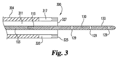
図3は、参照番号300を用いて、前方向きの超音波トランスデューサと共に使用される図1のガイド部材133の一例を示している。ガイド部材133は、内部管腔311を備える細長いキャリア本体304の遠位端327および遠位端に配置された血管内超音波プローブ320を越えて延在している。血管内超音波プローブ320は、細長いキャリア本体304の遠位端327の周囲に環状に配置された前向きのトランスデューサアレイ325を含む。ガイド部材133が前向きのトランスデューサアレイ325を越えて延在しているため、前向きのトランスデューサアレイ325から出射された超音波エネルギーが第1ガイド本体部130の周りを通過することができる。図1および2に示されたように、接合部113が血管内超音波プローブ320の近位に設けられるため、超音波強反射材料からなる第2ガイド本体部103が前向きのトランスデューサアレイ325の近位に位置し、主に超音波弱反射材料から形成された第1ガイド本体部130が遠位端327を超えて延在し、前向きのトランスデューサアレイ325の遠位に位置する。(図1および2に示されたように)細長いキャリア本体304の側壁を横方向に貫通する超音波エネルギーを出射する超音波トランスデューサを使用せず、複数のトランスデューサのアレイを配置することによって、トランスデューサアレイ325の前方から、遠位端327の遠位領域に向かって、超音波エネルギーを出射する。
FIG. 3 shows an example of the
血管内超音波プローブ320の一実施形態は、前向きのトランスデューサアレイ325に配置された一列の静電容量性小型超音波トランスデューサ(Capacitive Micromachined Ultrasonic Transducers、CMUT)を含む。したがって、超音波エネルギーは、トランスデューサアレイ325およびキャリア本体304の縦方向の前方に向けられる。アレイ325内に配置された要素は、集積回路317によって制御され、超音波エネルギーの出射および検出を行う。同様に、他の種類のトランスデューサまたはトランスデューサアレイ、例えば圧電トランスデューサを使用することもできる。この細長いキャリア本体304の例において、CMUTトランスデューサアレイは、単一の血管内腔カテーテルの遠位端に配置されている。他の構成、例えば、複数の血管内腔カテーテル構成、またはトランスデューサアレイを遠位端の周りに環状に配置するではなく、遠位端の隣りに配置する構成も考えられる。
One embodiment of the
図4は、図3に示された装置を使用して、患者の部分的に閉塞された内腔、例えば血管の血管内撮影などの撮影手順を示している。図4に示された血管400は、図2に示された血管と類似する。血管400は、血管内腔404を有する。血管内腔404には、細長いキャリア本体304およびキャリア本体の遠位端に連結されている血管内超音波プローブ320が挿入されている。血管内超音波プローブ320は、前向きのトランスデューサアレイ325を含む。超音波419は、前向きのトランスデューサアレイ325によって生成され、3次元の結像可能な領域411を形成する。ガイド部材133は、この結像可能な領域411内に位置する。図4に示すように、血管壁406の一部および血管閉塞物414も、トランスデューサアレイ325に対して相対的な位置で、造影可能な領域内411内に位置する。
FIG. 4 shows an imaging procedure, such as intravascular imaging of a partially occluded lumen of a patient, eg, a blood vessel, using the apparatus shown in FIG. The
前向きのトランスデューサアレイ325を作動させると、超音波エネルギー419は、血管内超音波プローブ320から出射され、細長いキャリア本体304の遠位端327を越えて、造影可能な領域411に進入し、造影可能な領域を通過する。造影可能な領域411は、細長いキャリア本体304の外部に位置し、血管内腔404の内容物、血管壁406、血管閉塞物414、場合によって、血管400外部の構造および組織の内容物を含む。前向きのトランスデューサアレイ325内の各個別のトランスデューサの動作は、集積回路317によって制御される。これによって、血管内超音波プローブ320は、動作して、造影可能な領域411の全体を3次元領域として撮影し、造影可能な領域内の構造物の特性、例えば体積、密度、血管内腔404を流通する流体の流速、領域内に発見され、決定することができる対象物の形状、サイズ、長さおよび他の特性を取得する。留意すべきことは、図4が造影可能な領域411の見かけ最大範囲を示しているが、図示からは、この最大範囲が存在するか否かまたはこの最大範囲がどこまで延在するかを決めることができないことである。一般的に、多くの要因は、超音波造影プローブの感知能力を決定する。その中でも、特定の患者の特別な属性、さまざまな臓器および組織構造に対する体内の特定の場所、出射されるエネルギーのパワーおよび周波数、並びに使用される前向きのトランスデューサアレイ325の特定の実施形態のさまざまな他の操作設定が、決定要因である。したがって、遠位端327を越えて延在する造影可能な領域411の範囲は、特に制限されない。
When the forward-facing
造影可能な領域411を通過する超音波エネルギーおよび反射される超音波の検出結果は、種々の情報を示す画像データ、例えば血管閉塞物414が血管内腔404内で延在する範囲、血管閉塞物414を構成する成分の種類および密度、並びに他の関連情報を示す3次元画像データ425である。これらの情報を収集するために、上述したように、細長いキャリア本体110は、トランスデューサリンク223を介して、画像データインタフェース装置233に連結される。その後、上述したように、データインターフェース装置233は、接続部材229を介して、画像データ表示装置227に連結される。造影可能な領域212の内部から反射された超音波は、画像データインターフェース装置233によってデータストリームに変換され、変換されたデータは、画像データ表示装置227に伝送される。伝送されたデータは、3次元画像データ425に処理され、造影可能な領域411の3次元画像としてまたは3次元画像データ425から抽出された2次元画像または「切片」の集合として表示される。臨床医は、表示された画像を観察する、閲覧する、後で患者に示すために保存する、医療記録に保管する、または他の目的のために使用することができる。
The detection result of the ultrasonic energy passing through the
図4に示されたガイド部材133を使用する時に、臨床医は、必要な手順に応じて、さまざまな方法を用いて、細長いキャリア本体304を体内の適切な箇所に挿入することができる。それと同時にまたは別の時間に、臨床医は、ガイド部材133を第1管腔311に挿入することができる。ガイド部材133を挿入するための動作の正確な順序は、システムの情報を収集するための用途に重要ではない。細長いキャリア本体304は、身体を通って、好ましくは血管などの血管内腔を通って、血管内超音波プローブ320によって撮影される体内部位に挿入される。この移動は、体内で細長いキャリア本体320をガイドする目的で、しばしば細長いキャリア本体の前方に挿入されるガイド部材133によって促進される。ガイド部材133の移動は、蛍光透視法、MRI撮影等の他の造影技術によって補助されてもよい。多くの場合、細長いキャリア本体304を前進させながら、血管内超音波プローブ320を操作して、画像データを取得することが有利であり得る。
When using the
図4は、ガイド部材133と共に使用される血管内超音波プローブ320の動作を示している。図4から分かるように、(図2と同様に)接合部113は、好ましくは、超音波トランスデューサ320の近位に、したがって造影可能な領域411の近位に配置される。このガイド部材133と血管内超音波プローブ320との相対的な配置によって、超音波弱反射材料を含む第1ガイド本体部130は、造影可能な領域411内に位置するガイド部材133の唯一の部分である。その結果、前向きのトランスデューサアレイ325から出射された超音波エネルギー419は、第1ガイド本体部130によって実質的に反射されず、主に第1ガイド本体部を通過する。したがって、第1ガイド本体部130は、実質的に画像データ425を干渉しない。このことは、さもなければより重要な情報を曖昧にし、より重要な情報の識別をより困難になり、または画像データ425を干渉することができる余分な情報が画像データ425に現れることを避けるため、好ましい。しかしながら、接合部113を前向きのトランスデューサアレイ325の遠位に配置するようにガイド部材133を設ける場合に、第2ガイド本体部103は、ガイド部材133を通過する超音波エネルギー419をブロックする超音波強反射材料で構成されているため、余分な情報、「ノイズ」、「陰影」または他の干渉物が画像データ425に現れ、画像データ425を干渉する。
FIG. 4 shows the operation of the
図2を参照して上述したように、血管内腔404内に位置するガイド部材133の超音波弱反射部分の位置を示す視覚指示を画像データ425に表示することは、臨床医にとって好ましい場合がある。このことは、臨床医が、超音波強反射マーカに依存して、血管内超音波プローブ320を自動的に位置付けることができる自動化撮影システムを操作する場合に、特に有用である。したがって、上述したように、少なくとも1つ、場合によって2つ以上の長手方向に離間した超音波強反射マーカ129は、ガイド部材133の第1ガイド本体部の一部として設けられる。超音波強反射マーカ129は、個別のマーカであってもよく、螺旋状、直線状、ストライプ状またはドット状などのさまざまなパターンに配置されたマーカ群を有するマーカ領域であってもよい(超音波強反射マーカおよびマーク領域のさまざまな実施例は、図5A〜図7Cに示されている)。超音波エネルギー419のうち少量の超音波エネルギーは、超音波強反射マーカ129によってまたはガイド部材133の構造に応じてガイド部材133によって、超音波トランスデューサアレイ325に反射されるが、大部分の超音波エネルギーは、ガイド部材133の他の部分を通過することができる。超音波強反射マーカ129は、第1ガイド部材130に比べてサイズが小さいため、画像データ425に現れ、第1ガイド本体部130の位置を示すとしても、実質的な視覚干渉を引き起こすことがない。したがって、超音波強反射マーカ129は、実質的な視覚干渉を引き起こすことなく、画像データ425に視覚指示を残しながら、臨床医のガイド部材133に対する操縦を支援する。
As described above with reference to FIG. 2, it may be preferable for the clinician to display the visual indication indicating the position of the ultrasonically weakly reflected portion of the
2次元または3次元の造影可能な領域、撮影される体内位置および撮影される構造の種類などの多くの要素に応じて、さまざまな種類の視覚指示は、必要とされる。図5A〜図7Cは、さまざまな配置の超音波強反射マーカまたは超音波強反射マーカ領域を有するガイド部材133に類似するガイド部材のさまざまな実施例を示している。図5A〜図7Cに示された実施形態の各々において、超音波強反射マーカは、図1〜4に示された超音波強反射マーカ129と同様に、さまざまな方法で配置されている。例えば、(図1〜図4に示された超音波強反射マーカ129のような)環状の超音波強反射マーカは、金属または他の音響反射材料などの超音波強反射材料からなる狭窄バンドをガイド部材(例えば、図1のガイド部材133)の外面に接着することによって作製することができる。同様に、ガイド部材の表面内または表面下に、超音波強反射材料からなる狭窄バンドを埋入することによって、同様の効果を達成することができる。他の実施形態、例えば、ガイド部材内に設けられた真空空洞、または窒素、空気または他のガスで充填した空洞、金属ビーズまたは金属フレークなどの超音波強反射材料の小切れ、または他の超音波強反射部材も考えられる。説明した超音波強反射マーカを作製するために、これらのさまざまな構造を併用してもよく、さまざまな組み合わせで使用してもよい。
Depending on a number of factors such as the 2D or 3D contrastable area, the location of the body being imaged and the type of structure being imaged, various types of visual indications are required. FIGS. 5A-7C illustrate various embodiments of guide members similar to guide
図5A、5Bおよび5Cは、ガイド部材500の例示を示している。ガイド部材500は、接合部504で接合された第1ガイド本体部510および第2ガイド本体部503を有する。超音波強反射マーカ506は、長手方向に沿って連続延在するように表示される。図5Aにおいて、超音波強反射マーカ506は、第1ガイド本体部510に沿って延在し且つ第1ガイド本体部510の長手方向軸に実質的に平行である単一の連続なリボンまたはバンドとして表示される。上述したように、超音波強反射マーカ506は、超音波強反射材料をガイド部材500の外面に接着することによって、または超音波強反射材料をガイド部材500内に埋入することによって、または第1ガイド本体部510内に超音波強反射構造または材料を設けるようにガイド部材500を製造することによって、作成することができる。同様に、撮影中に超音波強反射マーカ506を表示させるための他の技術を使用することもできる。図5Bにおいて、超音波強反射マーカ506は、螺旋パターンを形成するように、長手方向に連続延在する単一の超音波強反射マーカである。同様に、図5Cに示された超音波強反射マーカ506は、長手方向に連続延在する超音波強反射マーカである。この超音波強反射マーカ506は、マーカ材料または構造に設けられた不連続要素によって分離され、パターンを有する超音波強反射マーカ要素508として具体化される。この実施形態において、各個別の超音波強反射マーカ要素508は、単一の超音波強反射マーカ506の一部である。図5Cにおいて、各「ドット」(マーカ要素508)は、マーカ129に関して上述したように、個別の金属フレーク、金属ビーズ、気泡、または他の超音波強反射材料または構造であってもよい。
5A, 5B, and 5C show an example of the
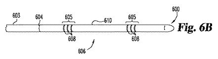
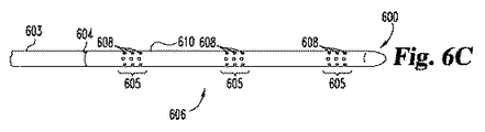
図6A、6Bおよび6Cは、第1ガイド本体部610を有するガイド部材600を示している。第1ガイド本体部610は、超音波強反射マーカ606を有する。超音波強反射マーカ606は、長手方向に離間された1つ以上の超音波強反射マーカ領域605からなるマーカパターンとして具体化される。マーカ領域605は、1つ以上の超音波強反射マーカ要素608を含む。前述の実施形態と同様に、第1ガイド本体部610は、接合部604で第2ガイド本体部603に接合される。図示のように、マーカ要素608は、超音波強反射材料または構造に設けられた不連続要素によって互いに分離されてもよい。各個別のマーカ要素608は、マーカ要素508およびマーカ129に関して上述したように構成される。したがって、図6Aに示された各個別の超音波強反射マーカ要素608は、超音波強反射「ドット」と見なされてもよい。図6Bに示された各個別の超音波強反射マーカ要素608は、超音波強反射環である。図6Cに示された各個別の超音波強反射マーカ要素608は、各マーカ領域605内に1つ以上の環状パターンで配置された個別のドットである。
6A, 6B and 6C show a
図7A、7Bおよび7Cは、ガイド部材700の例示を示している。ガイド部材700は、接合部704で接合された第1ガイド本体部710および第2ガイド本体部703を有する。第1ガイド本体部710に沿って離間された離散的な超音波強反射マーカ708は、さまざまな配置で設けられる。図7Aおよび7Bにおいて、複数の超音波強反射マーカ708は、上述したように個別の超音波強反射「ドット」として示される。図7Aにおいて、超音波強反射マーカ708は、直線状に配置されるが、図7Bにおいて、超音波強反射マーカ708は、螺旋状マーカパターンに配置される。
7A, 7B and 7C show an example of the
図7Cにおいて、各超音波強反射マーカ708は、ガイド部材700の周囲または外周の少なくとも一部の周りに配置されたバンドとして構成される。図5Cと同様に、図7A〜7Cに示された各「ドット」または環は、上述したように超音波強反射材料または構造から形成された個別の超音波強反射マーカ708、例えば、金属環、実心金属ビーズ、気泡、金属フレーク、ガス充填空洞、真空空洞、または他の超音波強反射材料部材を表す。
In FIG. 7C, each ultrasonic
本発明を説明する文脈に(特に特許請求の範囲の文脈に)使用された不定冠詞「a」/「an」、定冠詞「the」および同様の参照は、本明細書に特に明記しない限りまたは内容上明らかに他の意味を示す場合を除き、単数および複数の両方を含むように解釈すべきである。本明細書において、値の範囲の列挙は、単にその範囲内に含まれる各個別の値を各々言及する速記方法として意図され、本明細書に特に明記しない限り、各個別の値は、本明細書に個別に記載されるように、本明細書に組み込まれる。本明細書に特に明記しない限りまたは内容上明らかに他の意味を示す場合を除き、本明細書に記載のすべての方法は、任意の適切な順序で行うことができる。本明細書において、任意の例およびすべての例または例示的な言語(例えば、「〜のような」)の使用は、本発明をより明瞭にするよう意図されており、特に明記しない限り、本発明の範囲を限定するものではない。明細書内の用語は、本発明の実施に不可欠な任意の非請求要素を示すものと解釈すべきではない。 The indefinite article “a” / “an”, the definite article “the” and like references used in the context of describing the present invention (particularly in the context of the claims) or unless otherwise indicated herein. It should be interpreted to include both singular and plural unless the context clearly indicates otherwise. In this specification, the recitation of a range of values is intended merely as a shorthand way of referring to each individual value included within that range, and unless otherwise specified herein, each individual value is Are incorporated herein as if individually set forth in the document. All methods described herein can be performed in any suitable order unless otherwise indicated herein or otherwise clearly indicated by context. In this specification, the use of any and all examples or exemplary languages (eg, “such as”) is intended to make the present invention clearer, and unless stated otherwise, It is not intended to limit the scope of the invention. No language in the specification should be construed as indicating any non-claimed element essential to the practice of the invention.
図面および前述の説明において、本発明を詳細に説明してきたが、前述の説明は、例示であって、文言上本発明を限定するものではないと考えられるべきである。理解すべきことは、前述の説明は、好適な実施形態を図示および説明したのみであり、すべての変更および修正は、本発明の精神内に含まれ、保護されることである。さらに、本明細書に引用されたすべての参考文献は、当業者のレベルを示す指標であり、その全体が参考として本明細書に援用される。 While the invention has been described in detail in the drawings and foregoing description, the foregoing description is to be considered illustrative and not restrictive in terms of wording. It should be understood that the foregoing description has only shown and described the preferred embodiment, and all changes and modifications are included and protected within the spirit of the invention. Furthermore, all references cited herein are indicative of the level of ordinary skill in the art and are hereby incorporated by reference in their entirety.
以下の番号付けの請求項は、上述した具体的な実施形態を設定し、本開示の理解に有用である。 The following numbered claims set forth the specific embodiments described above and are useful for understanding the present disclosure.
1.血管内に挿入可能な装置であって、
血管内に通路を形成するための細長いキャリア本体を備え、前記キャリア本体は、少なくとも1つの内腔を規定し、前記キャリア本体の外部の造影可能な領域を表す画像データを生成するための少なくとも1つの血管内超音波プローブを運搬し、
前記内腔に収容可能な細長いガイド本体を有するガイド部材を備え、前記細長いガイド本体は、前記造影可能な領域に進入することができる少なくとも第1ガイド本体部を有し、
前記第1ガイド本体部は、超音波弱反射材料を含み、関連する少なくとも1つの超音波強反射マーカを有する、装置。
1. A device that can be inserted into a blood vessel,
An elongate carrier body for forming a passageway in a blood vessel, the carrier body defining at least one lumen and at least one for generating image data representing a contrastable region outside the carrier body Carrying two intravascular ultrasound probes,
A guide member having an elongate guide body that can be accommodated in the lumen, the elongate guide body having at least a first guide body part capable of entering the contrastable region;
The first guide body includes an ultrasonic weakly reflective material and has at least one ultrasonic strong reflective marker associated therewith.
2.第1項に記載の装置において、
前記細長いガイド本体は、互いに連結される少なくとも2つの長手方向に延在するガイド本体部分を含む。
2. In the apparatus according to item 1,
The elongate guide body includes at least two longitudinally extending guide body portions that are coupled together.
3.第2項に記載の装置において、
超音波強反射材料で形成された第2ガイド本体部をさらに備え、
前記細長いガイド本体は、少なくとも前記第2ガイド本体部に連結された前記第1ガイド本体部を含む。
3. In the apparatus according to item 2,
A second guide body formed of an ultrasonic strong reflection material;
The elongated guide body includes at least the first guide body part coupled to the second guide body part.
4.第2または3項に記載の装置において、
前記第1ガイド本体部は、ポリマ材料を含み、
前記第2ガイド本体部は、金属を含む。
4). In the apparatus according to item 2 or 3,
The first guide body includes a polymer material;
The second guide main body includes a metal.
5.第1〜4項のいずれか1項に記載の装置において、
前記少なくとも1つの超音波強反射マーカは、長手方向に離間された複数の超音波強反射マーカ領域を含む。
5). In the apparatus according to any one of Items 1 to 4,
The at least one ultrasonic strong reflection marker includes a plurality of ultrasonic strong reflection marker regions spaced in the longitudinal direction.
6.第1〜4項のいずれか1項に記載の装置において、
前記少なくとも1つの超音波強反射マーカは、複数の離散的な超音波強反射マーカまたは長手方向に延在する連続的な超音波強反射マーカを含む。
6). In the apparatus according to any one of Items 1 to 4,
The at least one ultrasonic strong reflection marker includes a plurality of discrete ultrasonic strong reflection markers or a continuous ultrasonic strong reflection marker extending in the longitudinal direction.
7.第61項に記載の装置において、
前記少なくとも1つの超音波強反射メーカは、前記長手方向に延在する連続的な超音波強反射マーカを含み、
前記長手方向に延在する連続的な超音波強反射マーカは、螺旋パターンを形成する。
7). In the apparatus of paragraph 61,
The at least one ultrasonic strong reflection maker includes a continuous ultrasonic strong reflection marker extending in the longitudinal direction;
The continuous ultrasonic reflection marker extending in the longitudinal direction forms a spiral pattern.
8.第1〜7項のいずれか1項に記載の装置において、
前記細長いキャリア本体は、カテーテルである。
8). The apparatus according to any one of Items 1 to 7,
The elongated carrier body is a catheter.
9.第1〜8項のいずれか1項に記載の装置において、
前記造影可能な領域は、実質的に2次元断面の切片である。
9. In the apparatus according to any one of Items 1 to 8,
The region that can be contrasted is substantially a two-dimensional section.
10.第1〜8項のいずれか1項に記載の装置において、
前記造影可能な領域は、3次元である。
10. In the apparatus according to any one of Items 1 to 8,
The region that can be contrasted is three-dimensional.
11.第1〜10項のいずれか1項に記載の装置において、
前記造影可能な領域は、前記超音波プローブの前方に位置する領域を含む。
11. In the apparatus according to any one of Items 1 to 10,
The region capable of being contrasted includes a region located in front of the ultrasonic probe.
12.第1〜11項のいずれか1項に記載の装置において、
前記第1ガイド本体部は、0.5g/cc〜3.5g/cc範囲の密度を有するポリマ材料を含む。
12 The apparatus according to any one of Items 1 to 11,
The first guide body includes a polymer material having a density in the range of 0.5 g / cc to 3.5 g / cc.
13.第1〜12項のいずれか1項に記載の装置において、
前記第1ガイド本体部は、約0.8g/cc〜約1.1g/cc範囲の密度を有するポリエチレンを含む。
13. In the apparatus according to any one of Items 1 to 12,
The first guide body includes polyethylene having a density in the range of about 0.8 g / cc to about 1.1 g / cc.
14.血管内超音波処置に使用されるガイドワイヤであって、
血管を通過するように構成された細長いガイド本体を備え、前記細長いガイド本体は、超音波弱反射材料を含む少なくとも第1ガイド本体部を有し、
前記第1ガイド本体部に関連された少なくとも1つの超音波強反射マーカを備える、ガイドワイヤ。
14 A guide wire used for intravascular ultrasound treatment,
An elongate guide body configured to pass through a blood vessel, the elongate guide body having at least a first guide body portion comprising an ultrasonically weakly reflective material;
A guide wire comprising at least one strong ultrasonic reflection marker associated with the first guide body.
15.第14項に記載のガイドワイヤにおいて、
前記細長いガイド本体は、互いに連結される少なくとも2つの長手方向に延在するガイド本体部分を含む。
15. In the guide wire of paragraph 14,
The elongate guide body includes at least two longitudinally extending guide body portions that are coupled together.
16.第14または15項に記載のガイドワイヤにおいて、
超音波強反射材料で形成された第2ガイド本体部をさらに備え、
前記細長いガイド本体は、少なくとも前記第2ガイド本体部に連結された前記第1ガイド本体部を含む。
16. The guidewire according to paragraph 14 or 15,
A second guide body formed of an ultrasonic strong reflection material;
The elongated guide body includes at least the first guide body part coupled to the second guide body part.
17.第15または16項に記載のガイドワイヤにおいて、
前記第1ガイド本体部は、ポリマ材料を含み、
前記第2ガイド本体部は、金属を含む。
17. The guidewire according to paragraph 15 or 16,
The first guide body includes a polymer material;
The second guide main body includes a metal.
18.第14〜17項のいずれか1項に記載のガイドワイヤにおいて、
前記少なくとも1つの超音波強反射マーカは、長手方向に離間された複数の超音波強反射マーカ領域を含む。
18. In the guide wire according to any one of Items 14 to 17,
The at least one ultrasonic strong reflection marker includes a plurality of ultrasonic strong reflection marker regions spaced in the longitudinal direction.
19.第14〜17項のいずれか1項に記載のガイドワイヤにおいて、
前記少なくとも1つの超音波強反射マーカは、複数の離散的な超音波強反射マーカまたは長手方向に延在する連続的な超音波強反射マーカを含む。
19. In the guide wire according to any one of Items 14 to 17,
The at least one ultrasonic strong reflection marker includes a plurality of discrete ultrasonic strong reflection markers or a continuous ultrasonic strong reflection marker extending in the longitudinal direction.
20.第19項に記載のガイドワイヤにおいて、
前記少なくとも1つの超音波強反射メーカは、前記長手方向に延在する連続的な超音波強反射マーカを含み、
前記長手方向に延在する連続的な超音波強反射マーカは、螺旋パターンを形成する。
20. In the guide wire of paragraph 19,
The at least one ultrasonic strong reflection maker includes a continuous ultrasonic strong reflection marker extending in the longitudinal direction;
The continuous ultrasonic reflection marker extending in the longitudinal direction forms a spiral pattern.
21.第14〜20項のいずれか1項に記載のガイドワイヤにおいて、
前記第1ガイド本体部は、0.5g/cc〜3.5g/cc範囲の密度を有するポリマ材料を含む。
21. In the guide wire according to any one of Items 14 to 20,
The first guide body includes a polymer material having a density in the range of 0.5 g / cc to 3.5 g / cc.
22.第14〜21項のいずれか1項に記載のガイドワイヤにおいて、
第1ガイド本体部は、約0.8g/cc〜約1.1g/cc範囲の密度を有するポリエチレンを含む。
22. In the guide wire according to any one of Items 14 to 21,
The first guide body includes polyethylene having a density in the range of about 0.8 g / cc to about 1.1 g / cc.
23.血管内処置であって、
細長いガイド本体を血管内に挿入するステップを備え、前記細長いガイド本体は、超音波弱反射材料を含む少なくとも第1ガイド本体部と、前記第1ガイド本体部に関連された少なくとも1つの超音波強反射マーカとを有し、
血管内超音波プローブを用いて、前記血管内の領域を撮影するステップを備え、前記撮影中に、前記第1ガイド本体部の少なくても一部は、前記領域内に配置される。
23. An endovascular procedure,
Inserting an elongate guide body into a blood vessel, the elongate guide body comprising at least a first guide body portion comprising an ultrasonically weakly reflective material and at least one ultrasonic intensity associated with the first guide body portion. A reflective marker,
The method includes imaging a region in the blood vessel using an intravascular ultrasonic probe, and at least a part of the first guide main body is disposed in the region during the imaging.
24.第23項に記載の方法において、
前記細長いガイド本体は、互いに連結される少なくとも2つの長手方向に延在するガイド本体部分を含む。
24. In the method of paragraph 23,
The elongate guide body includes at least two longitudinally extending guide body portions that are coupled together.
25.第24項に記載の方法において、
超音波強反射材料で形成された第2前記ガイド本体部をさらに備え、
前記細長いガイド本体は、少なくとも前記第2ガイド本体部に連結された前記第1ガイド本体部を含む。
25. In the method of paragraph 24,
A second guide body formed of an ultrasonic strong reflection material;
The elongated guide body includes at least the first guide body part coupled to the second guide body part.
26.第24または25項に記載の方法において、
前記第1ガイド本体部は、ポリマ材料を含み、
前記第2ガイド本体部は、金属を含む。
26. In the method of paragraph 24 or 25,
The first guide body includes a polymer material;
The second guide main body includes a metal.
27.第24〜26項のいずれか1項に記載の方法において、
前記少なくとも1つの超音波強反射マーカは、長手方向に離間された複数の超音波強反射マーカ領域を含む。
27. In the method of any one of paragraphs 24-26,
The at least one ultrasonic strong reflection marker includes a plurality of ultrasonic strong reflection marker regions spaced in the longitudinal direction.
28.第24〜26項のいずれか1項に記載の方法において、
前記少なくとも1つの超音波強反射マーカは、複数の離散的な超音波強反射マーカまたは長手方向に延在する連続的な超音波強反射マーカを含む。
28. In the method of any one of paragraphs 24-26,
The at least one ultrasonic strong reflection marker includes a plurality of discrete ultrasonic strong reflection markers or a continuous ultrasonic strong reflection marker extending in the longitudinal direction.
29.第28項に記載の方法において、
前記少なくとも1つの超音波強反射メーカは、前記長手方向に延在する連続的な超音波強反射マーカを含み、
前記長手方向に延在する連続的な超音波強反射マーカは、螺旋パターンを形成する。
29. In the method of paragraph 28,
The at least one ultrasonic strong reflection maker includes a continuous ultrasonic strong reflection marker extending in the longitudinal direction;
The continuous ultrasonic reflection marker extending in the longitudinal direction forms a spiral pattern.
30.第24〜29項のいずれか1項に記載の方法において、
前記第1ガイド本体部は、0.5g/cc〜3.5g/cc範囲の密度を有するポリマ材料を含む。
30. 30. The method according to any one of items 24 to 29,
The first guide body includes a polymer material having a density in the range of 0.5 g / cc to 3.5 g / cc.
31.第24〜30項のいずれか1項に記載の方法において、
前記第1ガイド本体部は、約0.8g/cc〜約1.1g/cc範囲の密度を有するポリエチレンを含む。
31. In the method according to any one of paragraphs 24-30,
The first guide body includes polyethylene having a density in the range of about 0.8 g / cc to about 1.1 g / cc.
Claims (31)
血管内に通路を形成するための細長いキャリア本体を備え、前記キャリア本体は、少なくとも1つの内腔を規定し、前記キャリア本体の外部の造影可能な領域を表す画像データを生成するための少なくとも1つの血管内超音波プローブを運搬し、
前記内腔に収容可能な細長いガイド本体を有するガイド部材を備え、前記細長いガイド本体は、前記造影可能な領域に進入することができる少なくとも第1ガイド本体部を有し、
前記第1ガイド本体部は、超音波弱反射材料を含み、関連する少なくとも1つの超音波強反射マーカを有する、装置。 A device that can be inserted into a blood vessel,
An elongate carrier body for forming a passageway in a blood vessel, the carrier body defining at least one lumen and at least one for generating image data representing a contrastable region outside the carrier body Carrying two intravascular ultrasound probes,
A guide member having an elongate guide body that can be accommodated in the lumen, the elongate guide body having at least a first guide body part capable of entering the contrastable region;
The first guide body includes an ultrasonic weakly reflective material and has at least one ultrasonic strong reflective marker associated therewith.
前記細長いガイド本体は、少なくとも前記第2ガイド本体部に連結された前記第1ガイド本体部を含む、請求項2に記載の装置。 A second guide body formed of an ultrasonic strong reflection material;
The apparatus of claim 2, wherein the elongate guide body includes at least the first guide body portion coupled to the second guide body portion.
前記第2ガイド本体部は、金属を含む、請求項2または3に記載の装置。 The first guide body includes a polymer material;
The apparatus according to claim 2, wherein the second guide main body includes a metal.
前記長手方向に延在する連続的な超音波強反射マーカは、螺旋パターンを形成する、請求項6に記載の装置。 The at least one ultrasonic strong reflection maker includes a continuous ultrasonic strong reflection marker extending in the longitudinal direction;
The apparatus according to claim 6, wherein the continuous ultrasonic strong reflection marker extending in the longitudinal direction forms a spiral pattern.
血管を通過するように構成された細長いガイド本体を備え、前記細長いガイド本体は、超音波弱反射材料を含む少なくとも第1ガイド本体部を有し、
前記第1ガイド本体部に関連された少なくとも1つの超音波強反射マーカを備える、ガイドワイヤ。 A guide wire used for intravascular ultrasound treatment,
An elongate guide body configured to pass through a blood vessel, the elongate guide body having at least a first guide body portion comprising an ultrasonically weakly reflective material;
A guide wire comprising at least one strong ultrasonic reflection marker associated with the first guide body.
前記細長いガイド本体は、少なくとも前記第2ガイド本体部に連結された前記第1ガイド本体部を含む、請求項14または15に記載のガイドワイヤ。 A second guide body formed of an ultrasonic strong reflection material;
The guide wire according to claim 14 or 15, wherein the elongated guide body includes at least the first guide body part coupled to the second guide body part.
前記第2ガイド本体部は、金属を含む、請求項15または16に記載のガイドワイヤ。 The first guide body includes a polymer material;
The guide wire according to claim 15 or 16, wherein the second guide main body portion includes a metal.
前記長手方向に延在する連続的な超音波強反射マーカは、螺旋パターンを形成する、請求項19に記載の装置。 The at least one ultrasonic strong reflection maker includes a continuous ultrasonic strong reflection marker extending in the longitudinal direction;
20. The apparatus of claim 19, wherein the longitudinally extending continuous strong ultrasound marker forms a spiral pattern.
細長いガイド本体を血管内に挿入するステップを備え、前記細長いガイド本体は、超音波弱反射材料を含む少なくとも第1ガイド本体部と、前記第1ガイド本体部に関連された少なくとも1つの超音波強反射マーカとを有し、
血管内超音波プローブを用いて、前記血管内の領域を撮影するステップを備え、前記撮影中に、前記第1ガイド本体部の少なくても一部は、前記領域内に配置される。 An endovascular procedure,
Inserting an elongate guide body into a blood vessel, the elongate guide body comprising at least a first guide body portion comprising an ultrasonically weakly reflective material and at least one ultrasonic intensity associated with the first guide body portion. A reflective marker,
The method includes imaging a region in the blood vessel using an intravascular ultrasonic probe, and at least a part of the first guide main body is disposed in the region during the imaging.
前記細長いガイド本体は、少なくとも前記第2ガイド本体部に連結された前記第1ガイド本体部を含む、請求項24に記載の方法。 A second guide body formed of an ultrasonic strong reflection material;
25. The method of claim 24, wherein the elongate guide body includes at least the first guide body portion coupled to the second guide body portion.
前記第2ガイド本体部は、金属を含む、請求項24または25に記載の方法。 The first guide body includes a polymer material;
26. A method according to claim 24 or 25, wherein the second guide body comprises a metal.
前記長手方向に延在する連続的な超音波強反射マーカは、螺旋パターンを形成する、請求項28に記載の方法。 The at least one ultrasonic strong reflection maker includes a continuous ultrasonic strong reflection marker extending in the longitudinal direction;
30. The method of claim 28, wherein the longitudinally extending continuous ultrasonic strong reflection marker forms a spiral pattern.
Applications Claiming Priority (3)
| Application Number | Priority Date | Filing Date | Title |
|---|---|---|---|
| US201461989679P | 2014-05-07 | 2014-05-07 | |
| US61/989,679 | 2014-05-07 | ||
| PCT/US2015/029229 WO2015171602A1 (en) | 2014-05-07 | 2015-05-05 | Guide members and associated apparatuses useful for intravascular ultrasound procedures |
Publications (2)
| Publication Number | Publication Date |
|---|---|
| JP2017514617A true JP2017514617A (en) | 2017-06-08 |
| JP6639413B2 JP6639413B2 (en) | 2020-02-05 |
Family
ID=54366895
Family Applications (1)
| Application Number | Title | Priority Date | Filing Date |
|---|---|---|---|
| JP2016566648A Active JP6639413B2 (en) | 2014-05-07 | 2015-05-05 | Apparatus with guide member and related equipment useful for intravascular ultrasonic treatment and endovascular treatment method (excluding human) |
Country Status (5)
| Country | Link |
|---|---|
| US (1) | US10485957B2 (en) |
| EP (1) | EP3139839B1 (en) |
| JP (1) | JP6639413B2 (en) |
| AU (1) | AU2015256182B2 (en) |
| WO (1) | WO2015171602A1 (en) |
Cited By (1)
| Publication number | Priority date | Publication date | Assignee | Title |
|---|---|---|---|---|
| WO2021200295A1 (en) * | 2020-03-31 | 2021-10-07 | テルモ株式会社 | Image processing device, image processing system, image display method, and image processing program |
Families Citing this family (4)
| Publication number | Priority date | Publication date | Assignee | Title |
|---|---|---|---|---|
| MX2018014612A (en) * | 2016-06-23 | 2019-03-01 | Avent Inc | Echogenic coil member for a catheter assembly. |
| CN211884905U (en) | 2019-08-22 | 2020-11-10 | 贝克顿·迪金森公司 | Balloon dilatation catheter and balloon thereof |
| US20210220620A1 (en) * | 2020-01-22 | 2021-07-22 | Baylis Medical Company Inc. | Medical guidewire assembly having identification device |
| US20210322731A1 (en) * | 2020-01-22 | 2021-10-21 | Baylis Medical Company Inc. | Medical guidewire assembly having identification device |
Citations (7)
| Publication number | Priority date | Publication date | Assignee | Title |
|---|---|---|---|---|
| JPH11506628A (en) * | 1995-06-06 | 1999-06-15 | カーディオヴァスキュラー イメイジング システムズ インコーポレイテッド | Rotational correlation between intravascular ultrasound image and guide catheter position |
| JP2002052079A (en) * | 2000-08-09 | 2002-02-19 | Hideo Nakajima | Medical instrument or member capable of ultrasonic diagnosis |
| US6475226B1 (en) * | 1999-02-03 | 2002-11-05 | Scimed Life Systems, Inc. | Percutaneous bypass apparatus and method |
| JP2005512664A (en) * | 2001-12-12 | 2005-05-12 | メドトロニック・インコーポレーテッド | Guide catheter |
| US20080154136A1 (en) * | 2005-12-02 | 2008-06-26 | Abbott Cardiovascular Systems Inc. | Visualization of a catheter viewed under ultrasound imaging |
| US20100056955A1 (en) * | 2008-09-04 | 2010-03-04 | Dean Peterson | Convertible guidewire system and methods |
| JP2012527317A (en) * | 2009-05-18 | 2012-11-08 | ヌームアールエックス・インコーポレーテッド | Method for correcting a cross section during deployment of an elongated lung volume reduction device |
Family Cites Families (14)
| Publication number | Priority date | Publication date | Assignee | Title |
|---|---|---|---|---|
| JP2002523152A (en) | 1998-08-19 | 2002-07-30 | クック インコーポレイティド | Preformed wire guide |
| GB2345543A (en) | 1999-01-06 | 2000-07-12 | Intravascular Res Ltd | Ultrasonic visualisation system with remote components |
| EP1040842B1 (en) | 1999-03-29 | 2004-05-12 | William Cook Europe ApS | A guidewire |
| WO2002054941A2 (en) * | 2001-01-11 | 2002-07-18 | Rita Medical Systems Inc | Bone-treatment instrument and method |
| US20040106891A1 (en) * | 2002-08-30 | 2004-06-03 | Inrad, Inc. | Localizing needle with fluid delivery |
| CN100558423C (en) * | 2003-12-18 | 2009-11-11 | 泰尔茂株式会社 | Leading line |
| US8430863B2 (en) * | 2005-12-02 | 2013-04-30 | Abbott Cardiovascular Systems Inc. | Visualization of a catheter viewed under ultrasound imaging |
| US20110021924A1 (en) | 2007-02-09 | 2011-01-27 | Shriram Sethuraman | Intravascular photoacoustic and utrasound echo imaging |
| JP2010520937A (en) * | 2007-03-09 | 2010-06-17 | ダウ グローバル テクノロジーズ インコーポレイティド | Stress crack / thermal crack resistant cable sheathing material |
| WO2010120913A2 (en) * | 2009-04-14 | 2010-10-21 | Maui Imaging, Inc. | Universal multiple aperture medical ultrasound probe |
| EP2558151A4 (en) * | 2010-04-13 | 2018-01-10 | Sentreheart, Inc. | Methods and devices for pericardial access |
| JP5888740B2 (en) * | 2012-06-13 | 2016-03-22 | 朝日インテック株式会社 | Guide wire |
| JP6661372B2 (en) * | 2012-10-12 | 2020-03-11 | マフィン・インコーポレイテッドMuffin Incorporated | Reciprocating internal ultrasonic transducer assembly |
| EP3384853B1 (en) * | 2013-03-06 | 2019-12-11 | Muffin Incorporated | Echolucent catheter |
-
2015
- 2015-05-05 WO PCT/US2015/029229 patent/WO2015171602A1/en active Application Filing
- 2015-05-05 US US14/704,236 patent/US10485957B2/en active Active
- 2015-05-05 EP EP15789395.9A patent/EP3139839B1/en active Active
- 2015-05-05 AU AU2015256182A patent/AU2015256182B2/en active Active
- 2015-05-05 JP JP2016566648A patent/JP6639413B2/en active Active
Patent Citations (7)
| Publication number | Priority date | Publication date | Assignee | Title |
|---|---|---|---|---|
| JPH11506628A (en) * | 1995-06-06 | 1999-06-15 | カーディオヴァスキュラー イメイジング システムズ インコーポレイテッド | Rotational correlation between intravascular ultrasound image and guide catheter position |
| US6475226B1 (en) * | 1999-02-03 | 2002-11-05 | Scimed Life Systems, Inc. | Percutaneous bypass apparatus and method |
| JP2002052079A (en) * | 2000-08-09 | 2002-02-19 | Hideo Nakajima | Medical instrument or member capable of ultrasonic diagnosis |
| JP2005512664A (en) * | 2001-12-12 | 2005-05-12 | メドトロニック・インコーポレーテッド | Guide catheter |
| US20080154136A1 (en) * | 2005-12-02 | 2008-06-26 | Abbott Cardiovascular Systems Inc. | Visualization of a catheter viewed under ultrasound imaging |
| US20100056955A1 (en) * | 2008-09-04 | 2010-03-04 | Dean Peterson | Convertible guidewire system and methods |
| JP2012527317A (en) * | 2009-05-18 | 2012-11-08 | ヌームアールエックス・インコーポレーテッド | Method for correcting a cross section during deployment of an elongated lung volume reduction device |
Cited By (1)
| Publication number | Priority date | Publication date | Assignee | Title |
|---|---|---|---|---|
| WO2021200295A1 (en) * | 2020-03-31 | 2021-10-07 | テルモ株式会社 | Image processing device, image processing system, image display method, and image processing program |
Also Published As
| Publication number | Publication date |
|---|---|
| JP6639413B2 (en) | 2020-02-05 |
| AU2015256182B2 (en) | 2019-11-14 |
| WO2015171602A1 (en) | 2015-11-12 |
| EP3139839A4 (en) | 2018-01-03 |
| US10485957B2 (en) | 2019-11-26 |
| EP3139839B1 (en) | 2024-01-24 |
| EP3139839A1 (en) | 2017-03-15 |
| US20150320979A1 (en) | 2015-11-12 |
| AU2015256182A1 (en) | 2016-12-15 |
Similar Documents
| Publication | Publication Date | Title |
|---|---|---|
| JP6639413B2 (en) | Apparatus with guide member and related equipment useful for intravascular ultrasonic treatment and endovascular treatment method (excluding human) | |
| JP4944045B2 (en) | System and method for predicting the length and position of a stent applied within a patient | |
| JP5420572B2 (en) | Improved visualization of catheters visible under ultrasound imaging | |
| EP2411963B1 (en) | Improvements to medical imaging | |
| CN105979879A (en) | Virtual image with optical shape sensing device perspective | |
| JP2008535560A (en) | 3D imaging for guided interventional medical devices in body volume | |
| KR101588014B1 (en) | Methods for Preparing Complex Reality Three-Dimensional Images and Systems therefor | |
| JP2013517039A (en) | Imaging device | |
| US20080071292A1 (en) | System and method for displaying the trajectory of an instrument and the position of a body within a volume | |
| US20230181148A1 (en) | Vascular system visualization | |
| US20190365351A1 (en) | Multi-patch array, ultrasound system, and method for obtaining an extended field of view | |
| JP2018527092A (en) | Device for characterizing blood vessels | |
| US9844361B2 (en) | Pulmonary ultrasound techniques for elastography in lungs | |
| EP3570756B1 (en) | System for imaging and tracking interventional devices | |
| JP2021186284A (en) | Ultrasonic imaging apparatus, treatment support system and image display method | |
| JP6794440B2 (en) | A device that characterizes the walls of blood vessels | |
| US11883114B2 (en) | Ultrasound locatable surgical guidewire system and method | |
| KR101727567B1 (en) | Methods for Preparing Complex Reality Three-Dimensional Images and Systems therefor |
Legal Events
| Date | Code | Title | Description |
|---|---|---|---|
| A621 | Written request for application examination |
Free format text: JAPANESE INTERMEDIATE CODE: A621 Effective date: 20180507 |
|
| A977 | Report on retrieval |
Free format text: JAPANESE INTERMEDIATE CODE: A971007 Effective date: 20190131 |
|
| A131 | Notification of reasons for refusal |
Free format text: JAPANESE INTERMEDIATE CODE: A131 Effective date: 20190219 |
|
| A521 | Request for written amendment filed |
Free format text: JAPANESE INTERMEDIATE CODE: A523 Effective date: 20190520 |
|
| A131 | Notification of reasons for refusal |
Free format text: JAPANESE INTERMEDIATE CODE: A131 Effective date: 20190723 |
|
| A521 | Request for written amendment filed |
Free format text: JAPANESE INTERMEDIATE CODE: A523 Effective date: 20191021 |
|
| TRDD | Decision of grant or rejection written | ||
| A01 | Written decision to grant a patent or to grant a registration (utility model) |
Free format text: JAPANESE INTERMEDIATE CODE: A01 Effective date: 20191203 |
|
| A61 | First payment of annual fees (during grant procedure) |
Free format text: JAPANESE INTERMEDIATE CODE: A61 Effective date: 20191224 |
|
| R150 | Certificate of patent or registration of utility model |
Ref document number: 6639413 Country of ref document: JP Free format text: JAPANESE INTERMEDIATE CODE: R150 |
|
| R250 | Receipt of annual fees |
Free format text: JAPANESE INTERMEDIATE CODE: R250 |
|
| R250 | Receipt of annual fees |
Free format text: JAPANESE INTERMEDIATE CODE: R250 |