EP3139701A1 - Materialbahn und heizelement - Google Patents
Materialbahn und heizelement Download PDFInfo
- Publication number
- EP3139701A1 EP3139701A1 EP16184149.9A EP16184149A EP3139701A1 EP 3139701 A1 EP3139701 A1 EP 3139701A1 EP 16184149 A EP16184149 A EP 16184149A EP 3139701 A1 EP3139701 A1 EP 3139701A1
- Authority
- EP
- European Patent Office
- Prior art keywords
- heating element
- conductive layer
- material web
- electrodes
- separating strip
- Prior art date
- Legal status (The legal status is an assumption and is not a legal conclusion. Google has not performed a legal analysis and makes no representation as to the accuracy of the status listed.)
- Granted
Links
Images


Classifications
-
- H—ELECTRICITY
- H05—ELECTRIC TECHNIQUES NOT OTHERWISE PROVIDED FOR
- H05B—ELECTRIC HEATING; ELECTRIC LIGHT SOURCES NOT OTHERWISE PROVIDED FOR; CIRCUIT ARRANGEMENTS FOR ELECTRIC LIGHT SOURCES, IN GENERAL
- H05B3/00—Ohmic-resistance heating
- H05B3/20—Heating elements having extended surface area substantially in a two-dimensional [2D] plane, e.g. plate-heater
- H05B3/34—Heating elements having extended surface area substantially in a two-dimensional [2D] plane, e.g. plate-heater flexible, e.g. heating nets or webs
-
- H—ELECTRICITY
- H05—ELECTRIC TECHNIQUES NOT OTHERWISE PROVIDED FOR
- H05B—ELECTRIC HEATING; ELECTRIC LIGHT SOURCES NOT OTHERWISE PROVIDED FOR; CIRCUIT ARRANGEMENTS FOR ELECTRIC LIGHT SOURCES, IN GENERAL
- H05B3/00—Ohmic-resistance heating
- H05B3/20—Heating elements having extended surface area substantially in a two-dimensional [2D] plane, e.g. plate-heater
- H05B3/22—Heating elements having extended surface area substantially in a two-dimensional [2D] plane, e.g. plate-heater non-flexible
- H05B3/26—Heating elements having extended surface area substantially in a two-dimensional [2D] plane, e.g. plate-heater non-flexible heating conductor mounted on insulating base
-
- H—ELECTRICITY
- H05—ELECTRIC TECHNIQUES NOT OTHERWISE PROVIDED FOR
- H05B—ELECTRIC HEATING; ELECTRIC LIGHT SOURCES NOT OTHERWISE PROVIDED FOR; CIRCUIT ARRANGEMENTS FOR ELECTRIC LIGHT SOURCES, IN GENERAL
- H05B2203/00—Aspects relating to Ohmic resistive heating covered by group H05B3/00
- H05B2203/017—Manufacturing methods or apparatus for heaters
-
- H—ELECTRICITY
- H05—ELECTRIC TECHNIQUES NOT OTHERWISE PROVIDED FOR
- H05B—ELECTRIC HEATING; ELECTRIC LIGHT SOURCES NOT OTHERWISE PROVIDED FOR; CIRCUIT ARRANGEMENTS FOR ELECTRIC LIGHT SOURCES, IN GENERAL
- H05B2203/00—Aspects relating to Ohmic resistive heating covered by group H05B3/00
- H05B2203/026—Heaters specially adapted for floor heating
-
- H—ELECTRICITY
- H05—ELECTRIC TECHNIQUES NOT OTHERWISE PROVIDED FOR
- H05B—ELECTRIC HEATING; ELECTRIC LIGHT SOURCES NOT OTHERWISE PROVIDED FOR; CIRCUIT ARRANGEMENTS FOR ELECTRIC LIGHT SOURCES, IN GENERAL
- H05B2203/00—Aspects relating to Ohmic resistive heating covered by group H05B3/00
- H05B2203/029—Heaters specially adapted for seat warmers
-
- H—ELECTRICITY
- H05—ELECTRIC TECHNIQUES NOT OTHERWISE PROVIDED FOR
- H05B—ELECTRIC HEATING; ELECTRIC LIGHT SOURCES NOT OTHERWISE PROVIDED FOR; CIRCUIT ARRANGEMENTS FOR ELECTRIC LIGHT SOURCES, IN GENERAL
- H05B2203/00—Aspects relating to Ohmic resistive heating covered by group H05B3/00
- H05B2203/036—Heaters specially adapted for garment heating
Definitions
- the invention relates to a material web comprising a conductive layer and at least one cover layer with an intermediate separating strip, a heating element, and a method for producing the heating element, especially for use in the motor vehicle.
- WO 2012/104826 A1 and RU 2 403 686 C1 describe electrodes that are sewn with insulating material.
- WO 98/09478 A1 describes electrodes sewn with multiple layers at once so that the conductive suture is placed on the surface.
- Heating foils are for example off EP 2 000 005 B1 known.
- Conductive layers are for example off DE 10 2005 026 031 A1 1 known.
- the object of the present invention is to provide a technology with which heating foils for seats and armrests in vehicles can be produced as simply as possible.
- the object underlying the invention is achieved in a first embodiment by a material web of a plurality of material layers, the at least one conductive layer for electrical current and at least have a cover layer, characterized in that between the at least one cover layer and the at least one conductive layer, at least one release strip is arranged perpendicular to the longitudinal direction of the material web, said release strip having an anti-adhesion coating at least on the surface facing the conductive layer.
- the precursor can be produced for example as a seat heater or a heater for an armrest as a roll product.
- the material web can be easily opened after the material web has been severed in the region of the separating strip.
- the conductive layer and optionally with einlamin convinced electrodes is possible to allow, for example, a subsequent contact.
- Perpendicular to the longitudinal direction of the web within the meaning of the invention also includes angles in a range of 80 ° to 100 °.
- the conductive layer is preferably an electrically conductive polymer film and / or woven carbon fibers.
- the conductive layer preferably comprises a carrier material, in particular a plastic or a binder and distributed in the carrier material electrically conductive pigments, characterized in that the electrically conductive pigments have a broad size distribution and / or different shapes.
- the carrier material comprises polyurethane, polyacrylate, polycarbonate or mixtures thereof.
- the electrically conductive pigments are finely dispersed within the carrier material.
- the electrically conductive pigments are carbon-based.
- the sheet resistance of the conductive layer is preferably in a range of 0.1 to 1 k ⁇ / m 2 .
- the resistivity of the conductive layer is preferably in a range of 3 to 300 ⁇ / ⁇ .
- the basis weight of the conductive layer is preferably in a range of 80 to 200 g / m 2 . Above this range, the layer may be brittle. Below this range, it is often difficult to process.
- the electrically conductive layer may comprise metallic and / or non-metallic conductive pigments.
- the electrically conductive layer has predominantly non-metallic conductive pigments. This embodiment makes it possible to achieve a particularly flexible contacting system.
- the electrically conductive layer may have a resistivity in a range of 0.01 to 10 ⁇ ⁇ cm. A specific resistance of 0.05 to 1 ⁇ ⁇ cm is preferred.
- the carbon is preferably present within a polymer matrix.
- the material of the polymer matrix is preferably polyurethane.
- the cover layer is preferably electrically insulating.
- the cover layer is a layer of film, woven material or non-woven, very particularly preferably polyurethane films or needle felt.
- the material of the cover layer is preferably thermoplastic, more preferably selected from polyurethane, polyester, polypropylene and / or polyethylene.
- the cover layer preferably has a thickness in a range of 0.01 to 2 mm.
- a carrier layer is arranged in the material web and / or the heating element on the other side of the conductive layer.
- This carrier layer is preferably electrically insulating.
- the carrier layer is preferably a layer of film, woven material or non-woven, very particularly preferably needle-punched nonwoven.
- the material of the carrier layer is preferably thermoplastic, more preferably selected from polyurethane, polyester, polypropylene and / or polyethylene.
- the carrier layer preferably has a thickness in a range of 0.1 to 2 mm.
- the cover layer and / or independently of the support layer have a basis weight in a range of 25 to 120 g / m 2 . Below this range, the fleece is no longer so easy to process. In addition, it may not take on the function of an electrical insulator. If the thickness is higher, it can happen that the material web can no longer be processed with a calender.
- the material web preferably has at least two electrodes between the cover layer and the conductive layer.
- the electrodes may be, for example, metal wires, metal seats, braided metal seats, metal bands or electrode bands.
- the electrodes are sewn with contact cables and in particular with strands of contact cables.
- a heating element could be produced in which the contact cables were connected to the electrodes in a particularly stable manner. Surprisingly, the contact cables could no longer be pulled out of the heating element with the usual effort of a person.
- the electrodes comprise or are preferably electrode bands to which contact cables are very particularly preferably connected.
- the electrode tapes are preferably a woven composite of one or more metal hoops, metal wires or braided metal hoops or braided metal wires and fibers or yarns or twines
- the material web and / or the heating element preferably have at least two electrically conductive electrode bands.
- the electrode bands are preferably arranged between the cover layer and the electrically conductive layer.
- the electrode bands preferably extend in the direction of the material web.
- the electrode bands preferably contain metal filaments.
- the metal of these metal filaments is preferably selected from copper, tin-plated copper, silver-plated copper, silver, gold or mixtures thereof.
- the electrode bands preferably have a width in a range of 0.3 to 5 cm.
- the electrode tapes preferably have a thickness in a range of 0.05 to 1 mm.
- the electrode bands preferably have a length which corresponds at least to the length of the material web and / or of the heating element.
- the electrode bands particularly preferably have silver-plated copper strands woven into textile.
- the distance between the electrodes or electrode bands to the edge of the material web and / or the heating element is preferably in a range of 0.1 to 20 cm.
- the distance between at least two electrodes or Electrode tapes are preferably in a range of 50 to 90% of the width of the material web and / or the heating element.
- At least one electrode band is preferably connected to a contact cable.
- the contact cable preferably has strands.
- the strands are preferably connected to the at least one electrode band, most preferably sewn.
- the strands are arranged in the heating element according to the invention between the electrode tape and the cover layer and / or the adhesive strip.
- the strands are sutured through the electrode band to the conductive layer. It has been found that this allows particularly low contact resistance and a particularly high strain relief can be realized.
- the electrodes in the heating element according to the invention are preferably sewn to the strands only in a range of 1 to 20 cm 2 .
- the electrodes or electrode tapes are sewn to the conductive layer in the region of the strands of the at least one contact cable.
- the strands are disposed between the electrodes and the cover layer.
- the electrodes or electrode strips are preferably spaced a constant distance apart. As a result, the heating power remains constant.
- the metal of the strands is preferably selected from copper, tin-plated copper, silver-plated copper, silver, gold or mixtures thereof.
- the suture is preferably metal or metallized polymer. Most preferably, the suture is silver-plated or copper-plated polyamide twisted yarn.
- the fiber weight of the suture is preferably in a range of 100 to 400 dtex. It has been found that, outside of this range, surprisingly, the electrical resistance of the contact between the contact cables or their strands and the electrodes became worse.
- the seam pattern is preferably a zig-zag pattern with intermediate stitches.
- the contact cables are preferably each insulated.
- the insulation is preferably removed at the end of the contact cable. Particularly preferably, the insulation is removed in a range of 0.5 to 5 cm.
- the strands of the contact cable are so blank, for example. In order for a particularly good electrical contact to occur, the strands at the end of the contact cable are preferably distributed over the entire width of the electrode or of the electrode band.
- the contact cable in the heating element according to the invention is preferably sewn to the electrode band and the conductive layer at the end of the electrode band.
- the insulation of the contact cable extends over a length in a range of 1 to 10 mm into the heating element.
- the electrodes or electrode bands are connected on the same side of the heating element, each with a contact cable.
- the separating strip may preferably be a double-sided adhesive strip, this adhesive strip having an adhesive layer and a protective film on the side facing the conductive layer.
- the surface with the release coating of the release strip may be a siliconized or a polytetrafluoroethylene coated surface.
- the adhesive strip may be a double-sided adhesive strip having a protective film on the side facing the conductive layer.
- This protective film may be, for example, siliconized paper.
- the protective film may, for example, be made of siliconized paper, PE film or PTFE film.
- the double-sided adhesive strip is glued to the inside of the cover layer;
- a protective film is preferably not removed, so that in the subsequent lamination of the complete band adhesion takes place with the conductive layer and / or the electrodes.
- the separating strip preferably has a protective film on only one of its two sides.
- the separating strip preferably has a width in a range of 2 to 10 cm.
- the separating strip preferably has a thickness in a range of 10 to 500 ⁇ m.
- the separating strip preferably has a length of at least the width of the material web and / or of the heating element.
- the separating strip is very particularly preferably also arranged between the electrode or the electrode strip and the covering layer.
- the layers are preferably glued together and / or laminated.
- the width of the material web according to the invention and / or the heating element according to the invention is preferably in a range of 3 to 150 cm.
- the thickness of the material web according to the invention and / or the heating element according to the invention is preferably in a range of 0.5 to 2 mm.
- the heating element has a thermal sensor or a thermocouple.
- This thermocouple is preferably arranged between the conductive layer and the cover layer or carrier layer.
- the cover layer is then connected to the conductive layer.
- the material web is completely severed in the middle of the separating strip.
- a double-sided adhesive tape is used as separating strip, in which one surface is adhesively bonded to the cover layer and a protective film is first arranged on the other surface. If the material web is then severed in the region of the double-sided adhesive tape, the conductive layer and the electrodes are easily accessible, and the latter can be easily sewn, for example, with contact cables or contact wires. Subsequently, the anti-adhesion coating or protective film may preferably be removed and the cover layer may be easily bonded to the conductive layer by squeezing.
- the object underlying the invention is achieved by a vehicle comprising a heating element according to the invention.
- FIG. 1 shows a material web 10 with a conductive layer 14 on which a cover layer 16 is applied. At regular intervals, there is a separating strip 30 between these layers 14, 16.
- FIG. 2 shows an enlarged detail of the FIG. 1 , Here it can be seen that the separating strip 30 has a protective film 34 between the layers 14, 16.
- the separating strip is provided on both sides with an adhesive layer 32 (not shown).
- FIG. 3 shows the heating element 12 before final assembly.
- the overlying cover layer 16 is separated from the conductive layer 14 by the release strip 30.
- an electrode tape 22 is adhered on the conductive layer 14.
- Strands 26 of the contact cable 24 are placed on the electrode strip 22 and are then fixed with the electrode strip 22 and the conductive layer 14 with a seam 28.
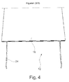
- FIG. 4 shows the heating element 12 with the cover layer 16 and the contact cables 24th
- polyester needle punched nonwoven fabric 70-80 g / m 2
- a material width of about 150 cm was stuck at intervals of 60 cm with 10 cm wide double-sided adhesive tape transversely to the running direction.
- the release paper remained on the adhesive layer.
- This prepared material served as a cover layer, the previously glued double-sided adhesive tapes with silicone paper served as a separating strip.
- the material web produced in this way was then cut through between the small distances (5 cm) of the electrode bands, whereby 5 rolls with a width of approx. 28 cm were produced.
- the narrower material webs were cut through at intervals of 30 cm between the separating strips and then exactly in the middle of the separating strips. In this way, individual precursors were obtained a heating element with a width of about 28 cm and a length of 30 cm.
- this "separation process” could also be carried out in one step (eg by punching out).
- the isolated heating element precursor has now been unfolded along the cut-through separating strip.
Landscapes
- Surface Heating Bodies (AREA)
- Resistance Heating (AREA)
Abstract
Description
- Die Erfindung betrifft eine Materialbahn aus einer leitfähigen Schicht und wenigstens einer Deckschicht mit dazwischenliegendem Trennstreifen, ein Heizelement, sowie ein Verfahren zur Herstellung des Heizelements speziell zur Verwendung im KFZ.
- Es sind bereits verschiedene Technologien bekannt, wie beispielsweise Sitzheizungen oder Heizungen für Armablagen realisiert werden können. Bislang ist es schwierig, diese möglichst hochautomatisiert anzufertigen.
-
WO 2012/104826 A1 undRU 2 403 686 C1 -
WO 98/09478 A1 - Heizfolien sind beispielsweise aus
EP 2 000 005 B1 bekannt. - Leitfähige Schichten sind beispielsweise aus
DE 10 2005 026 031 A1 1 bekannt. - Die Aufgabe der vorliegenden Erfindung besteht darin, eine Technologie bereitzustellen, mit der möglichst einfach beispielsweise Heizfolien für Sitze und Armauflagen in Fahrzeugen erzeugt werden können.
- Die der Erfindung zugrunde liegende Aufgabe wird in einer ersten Ausführungsform gelöst durch eine Materialbahn aus mehreren Materialschichten, die wenigstens eine für elektrischen Strom leitfähige Schicht und wenigstens eine Deckschicht aufweisen, dadurch gekennzeichnet, dass zwischen der wenigstens einen Deckschicht und der wenigstens einen leitfähigen Schicht wenigstens ein Trennstreifen senkrecht zur Längsrichtung der Materialbahn angeordnet ist, wobei dieser Trennstreifen wenigstens auf der der leitfähigen Schicht zugewandten Oberfläche eine Anti-Haft-Beschichtung aufweist.
- Dadurch kann das Vorprodukt beispielsweise zu einer Sitzheizung oder einer Heizung für eine Armauflage als Rollenware produziert werden.
- Durch den Trennstreifen lässt sich die Materialbahn nach der Durchtrennung der Materialbahn im Bereich des Trennstreifens einfach aufklappen. Damit ist eine nachträgliche Freilegung der leitfähigen Schicht und gegebenenfalls mit einlaminierten Elektroden möglich, um beispielsweise eine nachträgliche Kontaktierung zu ermöglichen.
- "Senkrecht zur Längsrichtung der Materialbahn" im Sinne der Erfindung schließt auch Winkel in einem Bereich von 80° bis 100° ein.
- Die der Erfindung zugrunde liegende Aufgabe wird in einer weiteren Ausführungsform gelöst durch ein Heizelement, das folgende Komponenten umfasst:
- a) wenigstens eine für elektrischen Strom leitfähige Schicht,
- b) wenigstens eine Deckschicht und
- c) wenigstens zwei Elektroden.
- Die leitfähige Schicht ist vorzugsweise eine elektrisch leitfähige Polymerfolie und/oder gewobene Carbonfasern.
- Die leitfähige Schicht umfasst vorzugsweise ein Trägermaterial, insbesondere einen Kunststoff oder ein Bindemittel und im Trägermaterial verteilte elektrisch leitfähige Pigmente, dadurch gekennzeichnet, dass die elektrisch leitfähigen Pigmente eine breite Größenverteilung und/oder unterschiedliche Formen aufweisen.
- Vorzugsweise weist das Trägermaterial Polyurethan, Polyacrylat, Polycarbonat oder Mischungen hiervon auf.
- Vorzugsweise liegen die elektrisch leitfähigen Pigmente fein dispergiert innerhalb des Trägermaterials vor.
- Vorzugsweise sind die elektrisch leitfähigen Pigmente kohlenstoffbasiert.
- Der Flächenwiderstand der leitfähigen Schicht liegt vorzugsweise in einem Bereich von 0,1 bis 1 kΩ/m2. Der spezifische Widerstand der leitfähigen Schicht liegt vorzugsweise in einem Bereich von 3 bis 300 Ω/□.
- Das Flächengewicht der leitfähigen Schicht liegt vorzugsweise in einem Bereich von 80 bis 200 g/m2. Oberhalb dieses Bereiches kann die Schicht brüchig sein. Unterhalb dieses Bereiches ist sie oft schwer verarbeitbar.
- Die elektrisch leitfähige Schicht kann metallische und/oder nichtmetallische Leitpigmente aufweisen.
- Es ist bevorzugt, wenn die elektrisch leitfähige Schicht überwiegend nichtmetallische Leitpigmente aufweist. Durch diese Ausgestaltung ist ein besonders flexibles Kontaktierungssystem erreichbar.
- Die elektrisch leitfähige Schicht kann einen spezifischen Widerstand in einem Bereich von 0,01 bis 10 Ω · cm aufweisen. Bevorzugt wird dabei ein spezifischer Widerstand von 0,05 bis 1 Ω · cm.
- Der Kohlenstoff liegt vorzugsweise innerhalb einer Polymermatrix vor. Das Material der Polymermatrix ist vorzugsweise Polyurethan.
- Die Deckschicht ist vorzugsweise elektrisch isolierend. Vorzugsweise handelt es sich bei der Deckschicht um eine Schicht aus Folie, gewebtem Material oder Vlies, ganz besonders bevorzugt Polyurethan-Folien oder Nadelvlies. Das Material der Deckschicht ist vorzugsweise thermoplastisch, insbesondere bevorzugt ausgewählt aus Polyurethan, Polyester, Polypropylen und/oder Polyethylen. Die Deckschicht weist vorzugsweise eine Dicke in einem Bereich von 0,01 bis 2 mm auf.
- Vorzugsweise ist in der Materialbahn und/oder dem Heizelement auf der anderen Seite der leitfähigen Schicht eine Trägerschicht angeordnet. Diese Trägerschicht ist vorzugsweise elektrisch isolierend. Vorzugsweise handelt es sich bei der Trägerschicht um eine Schicht aus Folie, gewebtem Material oder Vlies, ganz besonders bevorzugt Nadelvlies. Das Material der Trägerschicht ist vorzugsweise thermoplastisch, insbesondere bevorzugt ausgewählt aus Polyurethan, Polyester, Polypropylen und/oder Polyethylen. Die Trägerschichtweist vorzugsweise eine Dicke in einem Bereich von 0,1 bis 2 mm auf.
- Die Deckschicht und/oder unabhängig davon die Trägerschicht haben ein Flächengewicht in einem Bereich von 25 bis 120 g/m2. Unterhalb dieses Bereiches ist das Vlies nicht mehr so gut verarbeitbar. Zudem kann es möglicherweise nicht mehr die Funktion eines elektrischen Isolators übernehmen. Liegt die Dicke darüber, kann es passieren, dass die Materialbahn nicht mehr mit einem Kalander verarbeitet werden kann.
- Vorzugsweise weist die Materialbahn zwischen der Deckschicht und der leitfähigen Schicht wenigstens zwei Elektroden auf.
- Die Elektroden können beispielsweise Metalldrähte, Metallitzen, geflochtene Metallitzen, Metallbänder oder Elektrodenbänder sein.
- Vorzugsweise sind die Elektroden, insbesondere Elektrodenbänder bzw. Leitbänder, mit Kontaktkabeln und insbesondere mit Litzen von Kontaktkabeln vernäht. Im Unterschied zu bisherigen Technologien konnte so ein Heizelement hergestellt werden, bei dem die Kontaktkabel besonders stabil mit den Elektroden verbunden waren. Die Kontaktkabel konnten überraschenderweise so praktisch nicht mehr mit einem üblichen Kraftaufwand eines Menschen aus dem Heizelement herausgezogen werden.
- Die Elektroden umfassen oder sind vorzugsweise Elektrodenbänder, an die ganz besonders bevorzugt Kontaktkabel angeschlossen sind.
- Die Elektrodenbänder sind vorzugsweise ein gewobener Verbund aus einer oder mehrerer Metallitzen, Metalldrähten oder geflochtenen Metallitzen oder geflochtenen Metalldrähten und Fasern oder Garnen oder Zwirnen
- Die Materialbahn und/oder das Heizelement weisen vorzugsweise wenigstens zwei elektrisch leitfähige Elektrodenbänder auf. In der Materialbahn sind die Elektrodenbänder vorzugsweise zwischen der Deckschicht und der elektrisch leitfähigen Schicht angeordnet. Die Elektrodenbänder erstrecken sich vorzugsweise in Richtung der Materialbahn. Die Elektrodenbänder enthalten vorzugsweise Metallfäden. Das Metall dieser Metallfäden ist vorzugsweise ausgewählt aus Kupfer, verzinntem Kupfer, versilbertem Kupfer, Silber, Gold oder Mischungen derselben. Die Elektrodenbänder haben vorzugsweise eine Breite in einem Bereich von 0,3 bis 5 cm. Die Elektrodenbänder haben vorzugsweise eine Dicke in einem Bereich von 0,05 bis 1 mm. Die Elektrodenbänder haben vorzugsweise eine Länge, die wenigstens der Länge der Materialbahn und/oder des Heizelements entspricht.
- Die Elektrodenbänder weisen besonders bevorzugt in Textil eingewebte versilberte Kupferlitzen auf.
- Der Abstand der Elektroden oder Elektrodenbänder zum Rand der Materialbahn und/oder des Heizelements liegt vorzugsweise in einem Bereich von 0,1 bis 20 cm. Der Abstand zwischen wenigstens zwei Elektroden oder Elektrodenbändern liegt vorzugsweise in einem Bereich von 50 bis 90 % der Breite der Materialbahn und/oder des Heizelements. Wenigstens ein Elektrodenband ist vorzugsweise mit einem Kontaktkabel verbunden. Das Kontaktkabel weist vorzugsweise Litzen auf. Die Litzen sind vorzugsweise mit dem wenigstens einem Elektrodenband verbunden, ganz besonders bevorzugt vernäht. Ganz besonders bevorzugt sind die Litzen im erfindungsgemäßen Heizelement zwischen dem Elektrodenband und der Deckschicht und/oder dem Klebestreifen angeordnet. Vorzugsweise sind die Litzen durch das Elektrodenband hindurch mit der leitfähigen Schicht vernäht. Es hat sich herausgestellt, dass dadurch besonders niedrige Übergangswiderstände und eine besonders hohe Zugentlastung realisiert werden können.
- Die Elektroden im erfindungsgemäßen Heizelement sind vorzugsweise nur in einem Bereich von 1 bis 20 cm2 mit den Litzen vernäht. Vorzugsweise sind die Elektroden beziehungsweise Elektrodenbänder im Bereich der Litzen des wenigstens einen Kontaktkabels mit der leitfähigen Schicht vernäht. Vorzugsweise sind die Litzen zwischen den Elektroden und der Deckschicht angeordnet.Die Elektroden oder Elektrodenbänder sind vorzugsweise in gleichbleibendem Abstand voneinander entfernt. Dadurch bleibt die Heizleistung konstant.
- Das Metall der Litzen ist vorzugsweise ausgewählt aus Kupfer, verzinntem Kupfer, versilbertem Kupfer, Silber, Gold oder Mischungen derselben.
- Das Nahtmaterial ist vorzugsweise aus Metall oder metallisiertes Polymer. Ganz besonders bevorzugt ist das Nahtmaterial versilberter oder verkupferter Polyamid-Zwirn. Das Fasergewicht des Nahtmaterials liegt vorzugsweise in einem Bereich von 100 bis 400 dtex. Es hat sich herausgestellt, dass außerhalb dieses Bereiches überraschenderweise der elektrische Widerstand des Kontakts zwischen den Kontaktkabeln bzw. deren Litzen und den Elektroden schlechter wurde.
- Das Nahtmuster ist vorzugsweise ein Zick-Zack-Muster mit Zwischenstichen.
- Die Kontaktkabel sind vorzugsweise jeweils isoliert. Die Isolierung ist vorzugsweise am Ende der Kontaktkabel entfernt. Besonders bevorzugt ist die Isolierung in einem Bereich von 0,5 bis 5 cm entfernt. In dem Bereich, in dem die Isolierung des Kontaktkabels entfernt ist, liegen die Litzen des Kontaktkabels also beispielsweise blank. Damit es zu einem besonders guten elektrischen Kontakt kommt, sind die Litzen am Ende des Kontaktkabels vorzugsweise über die gesamte Breite der Elektrode oder des Elektrodenbandes verteilt.
- Vorzugsweise ist das Kontaktkabel im erfindungsgemäßen Heizelement am Ende des Elektrodenbandes mit dem Elektrodenband und der leitfähigen Schicht vernäht. Besonders bevorzugt erstreckt sich die Isolierung des Kontaktkabels über eine Länge in einem Bereich von 1 bis 10 mm in das Heizelement hinein. Dadurch kann ungewollter elektrischer Kontakt außerhalb des Heizelements besonders gut vermieden werden.
- Vorzugsweise sind die Elektroden oder Elektrodenbänder auf derselben Seite des Heizelements mit jeweils einem Kontaktkabel verbunden.
- Der Trennstreifen kann vorzugsweise ein doppelseitiger Klebestreifen sein, wobei dieser Klebestreifen auf der, der leitfähigen Schicht zugewandten Seite eine Klebeschicht und eine Schutzfolie aufweist.
- Die Oberfläche mit der Anti-Haft-Beschichtung des Trennstreifens kann eine silikonisierte oder eine mit Polytetrafluorethylen beschichtete Oberfläche sein.
- Der Klebestreifen kann ein doppelseitiger Klebestreifen sein, der auf der, der leitfähigen Schicht zugewandten Seite eine Schutzfolie aufweist. Diese Schutzfolie kann beispielsweise silikonisiertes Papier sein.
- Die Schutzfolie kann beispielsweise aus silikonisiertem Papier, PE-Folie oder PTFE-Folie betsehen.
- Vorzugsweise ist der doppelseitige Klebestreifen auf die Innenseite der Deckschicht geklebt; eine Schutzfolie ist vorzugsweise nicht entfernt, so dass bei der anschließenden Laminierung des kompletten Vebundes eine Verklebung mit der leitfähigen Schicht und/oder den Elektroden erfolgt. Vorzugsweise weist der Trennstreifen nur auf einer seiner beiden Seiten eine Schutzfolie auf.
- Der Trennstreifen weist vorzugsweise eine Breite in einem Bereich von 2 bis 10 cm auf. Der Trennstreifen weist vorzugsweise eine Dicke in einem Bereich von 10 bis 500 µm auf. Der Trennstreifen weist vorzugsweise eine Länge von wenigstens der Breite der Materialbahn und/oder des Heizelements auf.
- Der Trennstreifen ist ganz besonders bevorzugt auch zwischen der Elektrode beziehungsweise dem Elektrodenband und der Deckschicht angeordnet.
- Die Schichten sind vorzugsweise miteinander verklebt und/oder kaschiert.
- Die Breite der erfindungsgemäßen Materialbahn und/oder des erfindungsgemäßen Heizelements liegt vorzugsweise in einem Bereich von 3 bis 150 cm. Die Dicke der erfindungsgemäßen Materialbahn und/oder des erfindungsgemäßen Heizelements liegt vorzugsweise in einem Bereich von 0,5 bis 2 mm.
- Vorzugsweise weist das Heizelement einen Thermofühler oder ein Thermoelement auf. Dieser Thermofühler ist vorzugsweise zwischen der leitfähigen Schicht und der Deckschicht oder Trägerschicht angeordnet.
- Die der Erfindung zugrunde liegende Aufgabe wird in einer weiteren Ausführungsform gelöst durch ein Verfahren zur Herstellung des erfindungsgemäßen Heizelements, dadurch gekennzeichnet, dass man
- a) die erfindungsgemäße Materialbahn senkrecht zur Längsachse der Materialbahn unmittelbar am Rand des Trennstreifens oder im Bereich des Trennstreifens vollständig durchtrennt, so dass der Trennstreifen durch die Schutzfolie oder eine Anti-Haft-Beschichtung leicht von der leitfähigen Schicht trennbar ist und
- b) wenigstens zwei Elektroden mit Kontaktkabeln vernäht.
- Verzugsweise verbindet man anschließend die Deckschicht mit der leitfähigen Schicht.
- Vorzugsweise wird die Materialbahn in der Mitte des Trennstreifens vollständig durchtrennt.
- Vorzugsweise setzt man bei dem erfindungsgemäßen Verfahren als Trennstreifen ein doppelseitiges Klebeband ein, bei dem die eine Oberfläche mit der Deckschicht verklebt ist und auf der anderen Oberfläche zunächst eine Schutzfolie angeordnet ist. Wird dann die Materialbahn im Bereich des doppelseitigen Klebebandes durchtrennt, sind die leitfähige Schicht sowie die Elektroden leicht zugänglich und letztere können beispielsweise mit Kontaktkabeln oder Kontaktdrähten leicht vernäht werden. Anschließend kann die Anti-Haft-Beschichtung oder Schutzfolie vorzugsweise entfernt werden und die Deckschichtdurch zusammendrücken mit der leifähigen Schicht leicht verbunden werden.
- In einer weiteren Ausführungsform wird die der Erfindung zugrunde liegende Aufgabe gelöst durch ein Fahrzeug umfassend ein erfindungsgemäßes Heizelement.
- Weitere praktische Ausführungsformen und Vorteile der Erfindung sind nachfolgend im Zusammenhang mit den Zeichnungen beschrieben. Es zeigen:
- Fig. 1
- zeigt eine Materialbahn mit einer leitfähigen Schicht und einer auf die leitfähige Schicht aufgebrachten Deckschicht,
- Fig. 2
- zeigt eine Ausschnittsvergrößerung der
Fig. 1 , - Fig. 3
- zeigt das Heizelement vor dem endgültigen Zusammenbau und
- Fig. 4
- zeigt das Heizelement mit der Deckschicht und den Kontaktkabeln.
-
Figur 1 zeigt eine Materialbahn 10 mit einer leitfähigen Schicht 14, auf der eine Deckschicht 16 aufgebracht ist. In regelmäßigen Abständen befindet sich zwischen diesen Schichten 14, 16 ein Trennstreifen 30. -
Figur 2 zeigt eine Ausschnittsvergrößerung derFigur 1 . Hier ist erkennbar, dass der Trennstreifen 30 zwischen den Schichten 14, 16 eine Schutzfolie 34 aufweist. Der Trennstreifen ist beidseitig mit einer Klebeschicht 32 versehen (nicht dargestellt). -
Figur 3 zeigt das Heizelement 12 vor dem endgültigen Zusammenbau. Die obenliegende Deckschicht 16 ist durch den Trennstreifen 30 von der leitfähigen Schicht 14 getrennt. Auf der leitfähigen Schicht 14 ist ein Elektrodenband 22 aufgeklebt. Auf das Elektrodenband 22 sind Litzen 26 des Kontaktkabels 24 aufgelegt, die dann mit dem Elektrodenband 22 und der leitfähigen Schicht 14 mit einer Naht 28 fixiert sind. -
Figur 4 zeigt das Heizelement 12 mit der Deckschicht 16 und den Kontaktkabeln 24. - Handelsübliches Polyester-Nadelvlies (70-80 g/m2) mit einer Materialbreite von ca. 150 cm wurde in Abständen von 60 cm mit 10 cm breitem doppelseitigem Klebeband quer zur Laufrichtung beklebt. Das Trennpapier verblieb auf der Klebeschicht.
- Dieses vorbereitete Material diente als Deckschicht, die vorher aufgeklebten doppelseitigen Klebebänder mit Silikonpapier dienten als Trennstreifen.
- Anschließend wurden im Kalander folgende Materialien mit Hilfe geeigneter Klebematerialien in einem Schritt laminiert.
- 1. Handelsübliches Polyester Nadelvlies (70-80g/m2) (Trägerschicht).
- 2. FlexiWarm®- Folie (Breite ca. 146 cm bis 150 cm, der Firma Kaschier & Laminier ;Leitfähige Schicht).
- 3. 10 Elektrodenbänder mit folgenden Abständen 7,5 cm, 23 cm, 5 cm, 23 cm, 5 cm, 23 cm, 5 cm, 23 cm, 5 cm 23 cm, 7,5 cm. Dies entsprach einer Produktion von 5 Nutzen pro Laufmeter.
- 4. Die mit Streifen aus doppelseitigem Klebeband beklebte Deckschicht (siehe oben); die Schutzfolie war in Richtung der leitfähigen Schicht bzw. der Elektrodenbänder orientiert.
- So entstand die erfindungsgemäße Materialbahn.
- Die so gefertigte Materialbahn wurde nun zwischen den kleinen Abständen (5 cm) der Elektrodenbänder durchgeschnitten, wobei 5 Rollen mit einer Breite von ca. 28 cm entstanden.
- Im folgenden Arbeitsschritt wurden nun die schmaleren Materialbahnen jeweils im Abstand von 30 cm zwischen den Trennstreifen und dann exakt in der Mitte der Trennstreifen durchgeschnitten. Auf diese Weise erhielt man vereinzelte Vorstufen eines Heizelementes mit einer Breite von ca. 28 cm und einer Länge von 30 cm.
- Alternativ konnte dieser "Vereinzelungsprozess" auch in einem Schritt (z. B. durch Ausstanzen) durchgeführt werden.
- Die vereinzelte Heizelement-Vorstufe wurde nun entlang des durchgeschnittenen Trennstreifens aufgeklappt.
- Es wurden handelsübliche Kupferkabel mit Kupferlitzen am Ende 2 cm abisoliert. Die Litzen wurden verbreitert, so dass sie in Breite der Elektrodenbänder auf diese Elektrodenbänder aufgelegt wurden und mitsamt der darunterliegenden leitfähigen Schicht mit leitfähigem Zwirn (versilberter Polyamid-Zwirn) vernäht wurden. Dann wurde die Schutzfolie vom doppelseitigen Klebeband abgezogen und die Deckschicht mit der leitfähigen Schicht über die Kontaktkabel und Elektrodenbänder hinweg verklebt. So entstand das erfindungsgemäße Heizelement.
- Die in der vorliegenden Beschreibung, in den Zeichnungen sowie in den Ansprüchen offenbarten Merkmale der Erfindung können sowohl einzeln als auch in beliebigen Kombinationen für die Verwirklichung der Erfindung in ihren verschiedenen Ausführungsformen wesentlich sein. Die Erfindung ist nicht auf die beschriebenen Ausführungsformen beschränkt. Sie kann im Rahmen der Ansprüche und unter Berücksichtigung der Kenntnisse des zuständigen Fachmanns variiert werden.
-
- 10
- Materialbahn
- 12
- Heizelement
- 14
- Leitfähige Schicht
- 16
- Deckschicht
- 18
- Trägerschicht
- 20
- Elektroden
- 22
- Elektrodenband
- 24
- Kontaktkabel
- 26
- Litzen
- 28
- Naht
- 30
- Trennstreifen oder Klebestreifen
- 32
- Klebeschicht
- 34
- Schutzfolie
Claims (10)
- Materialbahn aus mehreren Materialschichten, die wenigstens eine für elektrischen Strom leitfähige Schicht (14) und wenigstens eine Deckschicht (16) (16) aufweist, dadurch gekennzeichnet, dass zwischen der wenigstens einen Deckschicht (16) und der wenigstens einen leitfähigen Schicht (14) wenigstens ein Trennstreifen (30) senkrecht zur Längsrichtung der Materialbahn (10) angeordnet ist, wobei dieser Trennstreifen (30) wenigstens auf der der leitfähigen Schicht (14) zugewandten Oberfläche einen Trennstreifen mit Anti-Haft-Beschichtung aufweist.
- Materialbahn gemäß Anspruch 1, dadurch gekennzeichnet, dass die Materialbahn (10) zwischen der Deckschicht (16) und der leitfähigen Schicht (14) zwei Elektroden (20) aufweist.
- Heizelement, das folgende Komponenten umfasst:a) wenigstens eine für elektrischen Strom leitfähige Schicht (14),b) wenigstens eine Deckschicht (16) undc) wenigstens zwei Elektroden (20).
- Heizelement gemäß Anspruch 3 oder Materialbahn gemäß Anspruch 1 oder 2, dadurch gekennzeichnet, dass der Trennstreifen (30) ein doppelseitiges Klebeband ist.
- Heizelement gemäß Anspruch 3 oder 4 oder Materialbahn gemäß Anspruch 1, 2 oder 4, dadurch gekennzeichnet, dass die leitfähige Schicht (14) eine elektrisch leitfähige Polymerfolie ist.
- Heizelement gemäß einem der Ansprüche 3 bis 5 oder Materialbahn gemäß einem der Ansprüche 2 oder 4 bis 5, dadurch gekennzeichnet, dass die Elektroden (20) Elektrodenbänder (22) umfassen, in denen ganz besonders bevorzugt Metallfäden enthalten sind.
- Heizelement gemäß einem der Ansprüche 3 bis 6, dadurch gekennzeichnet, dass die Elektroden (20) mit Litzen (26) von Kontaktkabeln (24) vernäht sind.
- Heizelement gemäß einem der Ansprüche 3 bis 7, dadurch gekennzeichnet, dass das Fasergewicht des Nahtmaterials in einem Bereich von 100 bis 400 dtex liegt.
- Verfahren zur Herstellung des Heizelements gemäß einem der Ansprüche 3 bis 8, dadurch gekennzeichnet, dass mana) die Materialbahn (10) gemäß einem der Ansprüche 1 bis 2 senkrecht zur Längsachse der Materialbahn (10) unmittelbar am Rand des Trennstreifens (30) oder im Bereich des Trennstreifens (30) vollständig durchtrennt, so dass der Trennstreifen (30) durch eine Schutzfolie oder eine Anti-Haft-Beschichtung leicht von der leitfähigen Schicht (14) trennbar ist undb) wenigstens zwei Elektroden (20) mit Kontaktkabeln (24) zumindest teilweise vernäht.
- Fahrzeug umfassend ein Heizelement (12) gemäß Anspruch 9.
Applications Claiming Priority (1)
| Application Number | Priority Date | Filing Date | Title |
|---|---|---|---|
| DE102015113921.9A DE102015113921A1 (de) | 2015-08-21 | 2015-08-21 | Materialbahn und Heizelement |
Publications (2)
| Publication Number | Publication Date |
|---|---|
| EP3139701A1 true EP3139701A1 (de) | 2017-03-08 |
| EP3139701B1 EP3139701B1 (de) | 2020-04-22 |
Family
ID=56800153
Family Applications (1)
| Application Number | Title | Priority Date | Filing Date |
|---|---|---|---|
| EP16184149.9A Active EP3139701B1 (de) | 2015-08-21 | 2016-08-15 | Materialbahn und heizelement |
Country Status (2)
| Country | Link |
|---|---|
| EP (1) | EP3139701B1 (de) |
| DE (1) | DE102015113921A1 (de) |
Citations (8)
| Publication number | Priority date | Publication date | Assignee | Title |
|---|---|---|---|---|
| WO1998009478A1 (en) | 1996-08-29 | 1998-03-05 | Arthur Gurevich | Heating element and method of manufacture |
| DE102005026031A1 (de) | 2005-06-03 | 2006-12-07 | Heitexx Ltd. | Elektrisch leitfähiges Material und ein Verfahren zur Herstellung eines elektrisch leitfähigen Materials |
| DE102007042644A1 (de) * | 2007-09-07 | 2009-03-12 | Benecke-Kaliko Ag | Elektrisch leitfähiges, flexibles Flächengebilde |
| EP2000005B1 (de) | 2006-03-21 | 2010-07-14 | Heitexx Ltd. | Kontaktierungssystem, heizelement und herstellung eines kontaktierungssystems und eines heizelements |
| EP2208461A1 (de) * | 2009-01-20 | 2010-07-21 | Leonh. Lang | Bioelektrode |
| RU2403686C1 (ru) | 2007-01-22 | 2010-11-10 | Панасоник Корпорэйшн | Листовой нагревательный элемент |
| WO2012104826A1 (pt) | 2011-02-04 | 2012-08-09 | Universidade Do Minho | Elétrodos baseados em substratos têxteis |
| EP2736304A1 (de) * | 2012-11-21 | 2014-05-28 | Sefar AG | Heizgewebe |
-
2015
- 2015-08-21 DE DE102015113921.9A patent/DE102015113921A1/de not_active Withdrawn
-
2016
- 2016-08-15 EP EP16184149.9A patent/EP3139701B1/de active Active
Patent Citations (8)
| Publication number | Priority date | Publication date | Assignee | Title |
|---|---|---|---|---|
| WO1998009478A1 (en) | 1996-08-29 | 1998-03-05 | Arthur Gurevich | Heating element and method of manufacture |
| DE102005026031A1 (de) | 2005-06-03 | 2006-12-07 | Heitexx Ltd. | Elektrisch leitfähiges Material und ein Verfahren zur Herstellung eines elektrisch leitfähigen Materials |
| EP2000005B1 (de) | 2006-03-21 | 2010-07-14 | Heitexx Ltd. | Kontaktierungssystem, heizelement und herstellung eines kontaktierungssystems und eines heizelements |
| RU2403686C1 (ru) | 2007-01-22 | 2010-11-10 | Панасоник Корпорэйшн | Листовой нагревательный элемент |
| DE102007042644A1 (de) * | 2007-09-07 | 2009-03-12 | Benecke-Kaliko Ag | Elektrisch leitfähiges, flexibles Flächengebilde |
| EP2208461A1 (de) * | 2009-01-20 | 2010-07-21 | Leonh. Lang | Bioelektrode |
| WO2012104826A1 (pt) | 2011-02-04 | 2012-08-09 | Universidade Do Minho | Elétrodos baseados em substratos têxteis |
| EP2736304A1 (de) * | 2012-11-21 | 2014-05-28 | Sefar AG | Heizgewebe |
Also Published As
| Publication number | Publication date |
|---|---|
| EP3139701B1 (de) | 2020-04-22 |
| DE102015113921A1 (de) | 2017-02-23 |
Similar Documents
| Publication | Publication Date | Title |
|---|---|---|
| EP1835786B1 (de) | Flächenheizelement und Verfahren zur Herstellung eines Flächenheizelementes | |
| EP3375693B1 (de) | Lenkradummantelung | |
| DE102015114778B4 (de) | Abstandsgewirke, Abstandsgewirkeabschnitt sowie beheizbares Verkleidungselement | |
| DE102011114949A1 (de) | Elektrischer Leiter | |
| DE102007010145A1 (de) | Elektrischer Leiter | |
| EP1777992A2 (de) | Flexibles Flächenheizelement, insbesondere für Sitzheizungen, und Verfahren zur Herstellung eines flexiblen Heizelements | |
| DE102009026216A1 (de) | Flexibles Flächengebilde | |
| DE102008018695A1 (de) | Materialverbund, bestehend aus einer metallischen Matrix, in der CNT-Filamente verteilt sind, sowie Verfahren zur Herstellung eines solchen Materialverbundes | |
| DE112020000971T5 (de) | Flexible und dehnbare Elektroheizung basierend auf einem elektrisch leitenden Textilmaterial und Verfahren zur Herstellung von dieser | |
| DE102020125367A1 (de) | Gurtband sowie Sicherheitsgurtsystem | |
| EP2844030A1 (de) | Heizgewebe | |
| EP1995738B1 (de) | Elektrischer Leiter | |
| DE102004022373B4 (de) | Mehrschichtiges übernähtes System | |
| EP3139701B1 (de) | Materialbahn und heizelement | |
| DE102009003867A1 (de) | Elektrisch leitendes Polymerband und Polymergewebe auf der Basis von elektrisch leitenden Polymerfasern, Garnen, Zwirnen und Schnüren für flächenhafte Heizelemente, Heizgewebe und ähnliches und Verfahren zur Herstellung des flächenhaften Heizelementes | |
| DE202011106363U1 (de) | Elektrischer Leiter | |
| EP2000005B1 (de) | Kontaktierungssystem, heizelement und herstellung eines kontaktierungssystems und eines heizelements | |
| DE102020129775B3 (de) | Funktionstextil, Verfahren zur Bildung eines Funktionstextils sowie Verwendung eines Funktionstextils | |
| DE102008051533A1 (de) | Verfahren zur Herstellung eines Bauteil-Halbzeuges und Verfahren zur Herstellung eines Bauteils | |
| DE102006038611A1 (de) | Abstandsgewirke mit korosionsfreien Leiterfäden | |
| DE102008063410A1 (de) | Verfahren zur Herstellung eines Bauteil-Halbzeuges, Verfahren zur Herstellung eines Bauteils sowie Bauteil mit einer Heizschicht | |
| EP1180915B1 (de) | Heizelement | |
| EP3834257B1 (de) | Verfahren zum herstellen eines elektrischen kontaktes | |
| EP1630825A2 (de) | Elektrische Leitung | |
| DE102010011946A1 (de) | Elektrische Heizvorrichtung |
Legal Events
| Date | Code | Title | Description |
|---|---|---|---|
| PUAI | Public reference made under article 153(3) epc to a published international application that has entered the european phase |
Free format text: ORIGINAL CODE: 0009012 |
|
| STAA | Information on the status of an ep patent application or granted ep patent |
Free format text: STATUS: THE APPLICATION HAS BEEN PUBLISHED |
|
| AK | Designated contracting states |
Kind code of ref document: A1 Designated state(s): AL AT BE BG CH CY CZ DE DK EE ES FI FR GB GR HR HU IE IS IT LI LT LU LV MC MK MT NL NO PL PT RO RS SE SI SK SM TR |
|
| AX | Request for extension of the european patent |
Extension state: BA ME |
|
| STAA | Information on the status of an ep patent application or granted ep patent |
Free format text: STATUS: REQUEST FOR EXAMINATION WAS MADE |
|
| 17P | Request for examination filed |
Effective date: 20170908 |
|
| RBV | Designated contracting states (corrected) |
Designated state(s): AL AT BE BG CH CY CZ DE DK EE ES FI FR GB GR HR HU IE IS IT LI LT LU LV MC MK MT NL NO PL PT RO RS SE SI SK SM TR |
|
| GRAP | Despatch of communication of intention to grant a patent |
Free format text: ORIGINAL CODE: EPIDOSNIGR1 |
|
| STAA | Information on the status of an ep patent application or granted ep patent |
Free format text: STATUS: GRANT OF PATENT IS INTENDED |
|
| INTG | Intention to grant announced |
Effective date: 20200108 |
|
| GRAS | Grant fee paid |
Free format text: ORIGINAL CODE: EPIDOSNIGR3 |
|
| GRAA | (expected) grant |
Free format text: ORIGINAL CODE: 0009210 |
|
| STAA | Information on the status of an ep patent application or granted ep patent |
Free format text: STATUS: THE PATENT HAS BEEN GRANTED |
|
| AK | Designated contracting states |
Kind code of ref document: B1 Designated state(s): AL AT BE BG CH CY CZ DE DK EE ES FI FR GB GR HR HU IE IS IT LI LT LU LV MC MK MT NL NO PL PT RO RS SE SI SK SM TR |
|
| REG | Reference to a national code |
Ref country code: CH Ref legal event code: EP |
|
| REG | Reference to a national code |
Ref country code: IE Ref legal event code: FG4D Free format text: LANGUAGE OF EP DOCUMENT: GERMAN |
|
| REG | Reference to a national code |
Ref country code: DE Ref legal event code: R096 Ref document number: 502016009620 Country of ref document: DE |
|
| REG | Reference to a national code |
Ref country code: AT Ref legal event code: REF Ref document number: 1261894 Country of ref document: AT Kind code of ref document: T Effective date: 20200515 |
|
| REG | Reference to a national code |
Ref country code: LT Ref legal event code: MG4D |
|
| REG | Reference to a national code |
Ref country code: NL Ref legal event code: MP Effective date: 20200422 |
|
| PG25 | Lapsed in a contracting state [announced via postgrant information from national office to epo] |
Ref country code: GR Free format text: LAPSE BECAUSE OF FAILURE TO SUBMIT A TRANSLATION OF THE DESCRIPTION OR TO PAY THE FEE WITHIN THE PRESCRIBED TIME-LIMIT Effective date: 20200723 Ref country code: NO Free format text: LAPSE BECAUSE OF FAILURE TO SUBMIT A TRANSLATION OF THE DESCRIPTION OR TO PAY THE FEE WITHIN THE PRESCRIBED TIME-LIMIT Effective date: 20200722 Ref country code: LT Free format text: LAPSE BECAUSE OF FAILURE TO SUBMIT A TRANSLATION OF THE DESCRIPTION OR TO PAY THE FEE WITHIN THE PRESCRIBED TIME-LIMIT Effective date: 20200422 Ref country code: FI Free format text: LAPSE BECAUSE OF FAILURE TO SUBMIT A TRANSLATION OF THE DESCRIPTION OR TO PAY THE FEE WITHIN THE PRESCRIBED TIME-LIMIT Effective date: 20200422 Ref country code: PT Free format text: LAPSE BECAUSE OF FAILURE TO SUBMIT A TRANSLATION OF THE DESCRIPTION OR TO PAY THE FEE WITHIN THE PRESCRIBED TIME-LIMIT Effective date: 20200824 Ref country code: NL Free format text: LAPSE BECAUSE OF FAILURE TO SUBMIT A TRANSLATION OF THE DESCRIPTION OR TO PAY THE FEE WITHIN THE PRESCRIBED TIME-LIMIT Effective date: 20200422 Ref country code: IS Free format text: LAPSE BECAUSE OF FAILURE TO SUBMIT A TRANSLATION OF THE DESCRIPTION OR TO PAY THE FEE WITHIN THE PRESCRIBED TIME-LIMIT Effective date: 20200822 Ref country code: SE Free format text: LAPSE BECAUSE OF FAILURE TO SUBMIT A TRANSLATION OF THE DESCRIPTION OR TO PAY THE FEE WITHIN THE PRESCRIBED TIME-LIMIT Effective date: 20200422 |
|
| PG25 | Lapsed in a contracting state [announced via postgrant information from national office to epo] |
Ref country code: RS Free format text: LAPSE BECAUSE OF FAILURE TO SUBMIT A TRANSLATION OF THE DESCRIPTION OR TO PAY THE FEE WITHIN THE PRESCRIBED TIME-LIMIT Effective date: 20200422 Ref country code: LV Free format text: LAPSE BECAUSE OF FAILURE TO SUBMIT A TRANSLATION OF THE DESCRIPTION OR TO PAY THE FEE WITHIN THE PRESCRIBED TIME-LIMIT Effective date: 20200422 Ref country code: HR Free format text: LAPSE BECAUSE OF FAILURE TO SUBMIT A TRANSLATION OF THE DESCRIPTION OR TO PAY THE FEE WITHIN THE PRESCRIBED TIME-LIMIT Effective date: 20200422 Ref country code: BG Free format text: LAPSE BECAUSE OF FAILURE TO SUBMIT A TRANSLATION OF THE DESCRIPTION OR TO PAY THE FEE WITHIN THE PRESCRIBED TIME-LIMIT Effective date: 20200722 |
|
| PG25 | Lapsed in a contracting state [announced via postgrant information from national office to epo] |
Ref country code: AL Free format text: LAPSE BECAUSE OF FAILURE TO SUBMIT A TRANSLATION OF THE DESCRIPTION OR TO PAY THE FEE WITHIN THE PRESCRIBED TIME-LIMIT Effective date: 20200422 |
|
| REG | Reference to a national code |
Ref country code: DE Ref legal event code: R097 Ref document number: 502016009620 Country of ref document: DE |
|
| PG25 | Lapsed in a contracting state [announced via postgrant information from national office to epo] |
Ref country code: ES Free format text: LAPSE BECAUSE OF FAILURE TO SUBMIT A TRANSLATION OF THE DESCRIPTION OR TO PAY THE FEE WITHIN THE PRESCRIBED TIME-LIMIT Effective date: 20200422 Ref country code: SM Free format text: LAPSE BECAUSE OF FAILURE TO SUBMIT A TRANSLATION OF THE DESCRIPTION OR TO PAY THE FEE WITHIN THE PRESCRIBED TIME-LIMIT Effective date: 20200422 Ref country code: DK Free format text: LAPSE BECAUSE OF FAILURE TO SUBMIT A TRANSLATION OF THE DESCRIPTION OR TO PAY THE FEE WITHIN THE PRESCRIBED TIME-LIMIT Effective date: 20200422 Ref country code: CZ Free format text: LAPSE BECAUSE OF FAILURE TO SUBMIT A TRANSLATION OF THE DESCRIPTION OR TO PAY THE FEE WITHIN THE PRESCRIBED TIME-LIMIT Effective date: 20200422 Ref country code: RO Free format text: LAPSE BECAUSE OF FAILURE TO SUBMIT A TRANSLATION OF THE DESCRIPTION OR TO PAY THE FEE WITHIN THE PRESCRIBED TIME-LIMIT Effective date: 20200422 Ref country code: EE Free format text: LAPSE BECAUSE OF FAILURE TO SUBMIT A TRANSLATION OF THE DESCRIPTION OR TO PAY THE FEE WITHIN THE PRESCRIBED TIME-LIMIT Effective date: 20200422 |
|
| PG25 | Lapsed in a contracting state [announced via postgrant information from national office to epo] |
Ref country code: PL Free format text: LAPSE BECAUSE OF FAILURE TO SUBMIT A TRANSLATION OF THE DESCRIPTION OR TO PAY THE FEE WITHIN THE PRESCRIBED TIME-LIMIT Effective date: 20200422 Ref country code: SK Free format text: LAPSE BECAUSE OF FAILURE TO SUBMIT A TRANSLATION OF THE DESCRIPTION OR TO PAY THE FEE WITHIN THE PRESCRIBED TIME-LIMIT Effective date: 20200422 |
|
| PLBE | No opposition filed within time limit |
Free format text: ORIGINAL CODE: 0009261 |
|
| STAA | Information on the status of an ep patent application or granted ep patent |
Free format text: STATUS: NO OPPOSITION FILED WITHIN TIME LIMIT |
|
| 26N | No opposition filed |
Effective date: 20210125 |
|
| PG25 | Lapsed in a contracting state [announced via postgrant information from national office to epo] |
Ref country code: MC Free format text: LAPSE BECAUSE OF FAILURE TO SUBMIT A TRANSLATION OF THE DESCRIPTION OR TO PAY THE FEE WITHIN THE PRESCRIBED TIME-LIMIT Effective date: 20200422 |
|
| REG | Reference to a national code |
Ref country code: CH Ref legal event code: PL |
|
| PG25 | Lapsed in a contracting state [announced via postgrant information from national office to epo] |
Ref country code: CH Free format text: LAPSE BECAUSE OF NON-PAYMENT OF DUE FEES Effective date: 20200831 Ref country code: LU Free format text: LAPSE BECAUSE OF NON-PAYMENT OF DUE FEES Effective date: 20200815 Ref country code: LI Free format text: LAPSE BECAUSE OF NON-PAYMENT OF DUE FEES Effective date: 20200831 |
|
| REG | Reference to a national code |
Ref country code: BE Ref legal event code: MM Effective date: 20200831 |
|
| PG25 | Lapsed in a contracting state [announced via postgrant information from national office to epo] |
Ref country code: SI Free format text: LAPSE BECAUSE OF FAILURE TO SUBMIT A TRANSLATION OF THE DESCRIPTION OR TO PAY THE FEE WITHIN THE PRESCRIBED TIME-LIMIT Effective date: 20200422 |
|
| PG25 | Lapsed in a contracting state [announced via postgrant information from national office to epo] |
Ref country code: IE Free format text: LAPSE BECAUSE OF NON-PAYMENT OF DUE FEES Effective date: 20200815 Ref country code: BE Free format text: LAPSE BECAUSE OF NON-PAYMENT OF DUE FEES Effective date: 20200831 |
|
| PG25 | Lapsed in a contracting state [announced via postgrant information from national office to epo] |
Ref country code: TR Free format text: LAPSE BECAUSE OF FAILURE TO SUBMIT A TRANSLATION OF THE DESCRIPTION OR TO PAY THE FEE WITHIN THE PRESCRIBED TIME-LIMIT Effective date: 20200422 Ref country code: MT Free format text: LAPSE BECAUSE OF FAILURE TO SUBMIT A TRANSLATION OF THE DESCRIPTION OR TO PAY THE FEE WITHIN THE PRESCRIBED TIME-LIMIT Effective date: 20200422 Ref country code: CY Free format text: LAPSE BECAUSE OF FAILURE TO SUBMIT A TRANSLATION OF THE DESCRIPTION OR TO PAY THE FEE WITHIN THE PRESCRIBED TIME-LIMIT Effective date: 20200422 |
|
| PG25 | Lapsed in a contracting state [announced via postgrant information from national office to epo] |
Ref country code: MK Free format text: LAPSE BECAUSE OF FAILURE TO SUBMIT A TRANSLATION OF THE DESCRIPTION OR TO PAY THE FEE WITHIN THE PRESCRIBED TIME-LIMIT Effective date: 20200422 |
|
| REG | Reference to a national code |
Ref country code: AT Ref legal event code: MM01 Ref document number: 1261894 Country of ref document: AT Kind code of ref document: T Effective date: 20210815 |
|
| PG25 | Lapsed in a contracting state [announced via postgrant information from national office to epo] |
Ref country code: AT Free format text: LAPSE BECAUSE OF NON-PAYMENT OF DUE FEES Effective date: 20210815 |
|
| PGFP | Annual fee paid to national office [announced via postgrant information from national office to epo] |
Ref country code: IT Payment date: 20250829 Year of fee payment: 10 |
|
| PGFP | Annual fee paid to national office [announced via postgrant information from national office to epo] |
Ref country code: GB Payment date: 20250818 Year of fee payment: 10 |
|
| PGFP | Annual fee paid to national office [announced via postgrant information from national office to epo] |
Ref country code: FR Payment date: 20250821 Year of fee payment: 10 |
|
| PGFP | Annual fee paid to national office [announced via postgrant information from national office to epo] |
Ref country code: DE Payment date: 20251029 Year of fee payment: 10 |