EP3139194A1 - A close range filtering fmcw radar - Google Patents
A close range filtering fmcw radar Download PDFInfo
- Publication number
- EP3139194A1 EP3139194A1 EP15183546.9A EP15183546A EP3139194A1 EP 3139194 A1 EP3139194 A1 EP 3139194A1 EP 15183546 A EP15183546 A EP 15183546A EP 3139194 A1 EP3139194 A1 EP 3139194A1
- Authority
- EP
- European Patent Office
- Prior art keywords
- signals
- radar
- received
- signal
- signal cycle
- Prior art date
- Legal status (The legal status is an assumption and is not a legal conclusion. Google has not performed a legal analysis and makes no representation as to the accuracy of the status listed.)
- Granted
Links
Images


Classifications
-
- G—PHYSICS
- G01—MEASURING; TESTING
- G01S—RADIO DIRECTION-FINDING; RADIO NAVIGATION; DETERMINING DISTANCE OR VELOCITY BY USE OF RADIO WAVES; LOCATING OR PRESENCE-DETECTING BY USE OF THE REFLECTION OR RERADIATION OF RADIO WAVES; ANALOGOUS ARRANGEMENTS USING OTHER WAVES
- G01S13/00—Systems using the reflection or reradiation of radio waves, e.g. radar systems; Analogous systems using reflection or reradiation of waves whose nature or wavelength is irrelevant or unspecified
- G01S13/88—Radar or analogous systems specially adapted for specific applications
- G01S13/93—Radar or analogous systems specially adapted for specific applications for anti-collision purposes
- G01S13/931—Radar or analogous systems specially adapted for specific applications for anti-collision purposes of land vehicles
-
- G—PHYSICS
- G01—MEASURING; TESTING
- G01S—RADIO DIRECTION-FINDING; RADIO NAVIGATION; DETERMINING DISTANCE OR VELOCITY BY USE OF RADIO WAVES; LOCATING OR PRESENCE-DETECTING BY USE OF THE REFLECTION OR RERADIATION OF RADIO WAVES; ANALOGOUS ARRANGEMENTS USING OTHER WAVES
- G01S13/00—Systems using the reflection or reradiation of radio waves, e.g. radar systems; Analogous systems using reflection or reradiation of waves whose nature or wavelength is irrelevant or unspecified
- G01S13/02—Systems using reflection of radio waves, e.g. primary radar systems; Analogous systems
- G01S13/06—Systems determining position data of a target
- G01S13/08—Systems for measuring distance only
- G01S13/32—Systems for measuring distance only using transmission of continuous waves, whether amplitude-, frequency-, or phase-modulated, or unmodulated
- G01S13/34—Systems for measuring distance only using transmission of continuous waves, whether amplitude-, frequency-, or phase-modulated, or unmodulated using transmission of continuous, frequency-modulated waves while heterodyning the received signal, or a signal derived therefrom, with a locally-generated signal related to the contemporaneously transmitted signal
-
- G—PHYSICS
- G01—MEASURING; TESTING
- G01S—RADIO DIRECTION-FINDING; RADIO NAVIGATION; DETERMINING DISTANCE OR VELOCITY BY USE OF RADIO WAVES; LOCATING OR PRESENCE-DETECTING BY USE OF THE REFLECTION OR RERADIATION OF RADIO WAVES; ANALOGOUS ARRANGEMENTS USING OTHER WAVES
- G01S13/00—Systems using the reflection or reradiation of radio waves, e.g. radar systems; Analogous systems using reflection or reradiation of waves whose nature or wavelength is irrelevant or unspecified
- G01S13/02—Systems using reflection of radio waves, e.g. primary radar systems; Analogous systems
- G01S13/06—Systems determining position data of a target
- G01S13/08—Systems for measuring distance only
- G01S13/32—Systems for measuring distance only using transmission of continuous waves, whether amplitude-, frequency-, or phase-modulated, or unmodulated
- G01S13/34—Systems for measuring distance only using transmission of continuous waves, whether amplitude-, frequency-, or phase-modulated, or unmodulated using transmission of continuous, frequency-modulated waves while heterodyning the received signal, or a signal derived therefrom, with a locally-generated signal related to the contemporaneously transmitted signal
- G01S13/342—Systems for measuring distance only using transmission of continuous waves, whether amplitude-, frequency-, or phase-modulated, or unmodulated using transmission of continuous, frequency-modulated waves while heterodyning the received signal, or a signal derived therefrom, with a locally-generated signal related to the contemporaneously transmitted signal using sinusoidal modulation
-
- G—PHYSICS
- G01—MEASURING; TESTING
- G01S—RADIO DIRECTION-FINDING; RADIO NAVIGATION; DETERMINING DISTANCE OR VELOCITY BY USE OF RADIO WAVES; LOCATING OR PRESENCE-DETECTING BY USE OF THE REFLECTION OR RERADIATION OF RADIO WAVES; ANALOGOUS ARRANGEMENTS USING OTHER WAVES
- G01S13/00—Systems using the reflection or reradiation of radio waves, e.g. radar systems; Analogous systems using reflection or reradiation of waves whose nature or wavelength is irrelevant or unspecified
- G01S13/02—Systems using reflection of radio waves, e.g. primary radar systems; Analogous systems
- G01S13/50—Systems of measurement based on relative movement of target
- G01S13/52—Discriminating between fixed and moving objects or between objects moving at different speeds
- G01S13/538—Discriminating between fixed and moving objects or between objects moving at different speeds eliminating objects that have not moved between successive antenna scans, e.g. area MTi
-
- G—PHYSICS
- G01—MEASURING; TESTING
- G01S—RADIO DIRECTION-FINDING; RADIO NAVIGATION; DETERMINING DISTANCE OR VELOCITY BY USE OF RADIO WAVES; LOCATING OR PRESENCE-DETECTING BY USE OF THE REFLECTION OR RERADIATION OF RADIO WAVES; ANALOGOUS ARRANGEMENTS USING OTHER WAVES
- G01S7/00—Details of systems according to groups G01S13/00, G01S15/00, G01S17/00
- G01S7/02—Details of systems according to groups G01S13/00, G01S15/00, G01S17/00 of systems according to group G01S13/00
- G01S7/35—Details of non-pulse systems
- G01S7/352—Receivers
-
- G—PHYSICS
- G01—MEASURING; TESTING
- G01S—RADIO DIRECTION-FINDING; RADIO NAVIGATION; DETERMINING DISTANCE OR VELOCITY BY USE OF RADIO WAVES; LOCATING OR PRESENCE-DETECTING BY USE OF THE REFLECTION OR RERADIATION OF RADIO WAVES; ANALOGOUS ARRANGEMENTS USING OTHER WAVES
- G01S7/00—Details of systems according to groups G01S13/00, G01S15/00, G01S17/00
- G01S7/02—Details of systems according to groups G01S13/00, G01S15/00, G01S17/00 of systems according to group G01S13/00
- G01S7/35—Details of non-pulse systems
- G01S7/352—Receivers
- G01S7/356—Receivers involving particularities of FFT processing
-
- G—PHYSICS
- G01—MEASURING; TESTING
- G01S—RADIO DIRECTION-FINDING; RADIO NAVIGATION; DETERMINING DISTANCE OR VELOCITY BY USE OF RADIO WAVES; LOCATING OR PRESENCE-DETECTING BY USE OF THE REFLECTION OR RERADIATION OF RADIO WAVES; ANALOGOUS ARRANGEMENTS USING OTHER WAVES
- G01S13/00—Systems using the reflection or reradiation of radio waves, e.g. radar systems; Analogous systems using reflection or reradiation of waves whose nature or wavelength is irrelevant or unspecified
- G01S13/88—Radar or analogous systems specially adapted for specific applications
- G01S13/93—Radar or analogous systems specially adapted for specific applications for anti-collision purposes
- G01S13/931—Radar or analogous systems specially adapted for specific applications for anti-collision purposes of land vehicles
- G01S2013/93185—Controlling the brakes
Definitions
- the present disclosure relates to a vehicle radar system comprising a transceiver arrangement that is arranged to generate and transmit at least a first radar signal cycle and a following second radar signal cycle.
- a first radar signal cycle a corresponding first received signal and corresponding first received signal information is obtained
- a following second radar signal cycle a corresponding second received signal and corresponding second received signal information is obtained.
- a chirp signal is an FMCW (Frequency Modulated Continuous Wave) signal with a certain amplitude where the frequency is continuously ramped between two values, the chirp signal thus being in the form of a continuous sinusoid where the frequency varies from a first low frequency to a second high frequency over the course of the ramp.
- the ramp may be such that the frequency varies from a first high frequency to a second low frequency.
- the magnitude of the change in frequency from start to finish may for example be of the order of 0.5% of the starting frequency.
- the received signals are mixed with the transmitted chirp signal in order to convert the received signals to baseband signals.
- These baseband signals or IF (Intermediate Frequency) signals, are amplified and transferred in a plurality of channels to an Analog Digital Converter (ADC) arrangement which is arranged to convert the received analog signals to digital signals.
- ADC Analog Digital Converter
- the digital signals are used for retrieving an azimuth angle of possible targets by simultaneously sampling and analyzing phase and amplitude of the received signals.
- the analysis is generally performed in one or more Digital Signal Processors (DSP:s) by means of Fast Fourier Transform (FFT) processing.
- DSP Digital Signal Processors
- FFT Fast Fourier Transform
- the radar signals are transmitted at a wavelength having a magnitude of for example one or a few centimeters, which is advantageous in order to be able to effectively avoid collisions.
- This also enables detection of objects that are close to the vehicle where a radar system is used. Due to reflections and multipath due to the vehicle itself, as well as collected dirt and similar, internal coupling of signals within the radar system, stationary objects that are close to the vehicle are detected and processed, which is disadvantageous since it these objects constitute unimportant detection and causes unnecessary data processing and can cause false association with a real desired object detection. These undesired detections cannot be distinguished from desired detections from close real objects.
- the object of the present disclosure is thus to provide a vehicle radar system where such close stationary objects are removed at an early stage, avoiding the above disadvantages.
- a vehicle radar system comprising a vehicle radar system comprising a transceiver arrangement that is arranged to generate and transmit at least a first radar signal cycle and a following second radar signal cycle.
- a first radar signal cycle a corresponding first received signal and corresponding first received signal information is obtained
- a following second radar signal cycle a corresponding second received signal and corresponding second received signal information is obtained.
- the vehicle radar system is arranged to calculate a difference between the first received signal information and the second received signal information.
- the vehicle radar system is arranged to:
- the first received signal information is constituted by received digital IF signals for a first radar signal cycle and that the second received signal information is constituted by received digital IF signals for a second radar signal cycle.
- the vehicle radar system is arranged to:
- the first received signal information is constituted by an output of a DSP arrangement for a first radar signal cycle.
- the second received signal information is constituted by an output of the DSP arrangement for a second radar signal cycle.
- the output of the DSP arrangement comprises Range-Doppler matrices.
- the vehicle radar system is arranged to:
- each radar signal cycle comprises an FMCW chirp signal cycle, where each chirp signal cycle comprises a corresponding plurality of frequency ramps.
- Each frequency ramp is arranged to run between a first frequency and a second frequency.
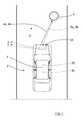
- Figure 1 schematically shows a top view of a vehicle 1 arranged to run on a road 2 in a direction D, where the vehicle 1 comprises a vehicle radar system 3 which is arranged to distinguish and/or resolve single targets from the surroundings by transmitting signals 4a, 4b and receiving reflected signals 5a, 5b and using a Doppler effect in a previously well-known manner.
- the vehicle radar system 3 is arranged to provide azimuth angles of possible objects 25, 6 by simultaneously sampling and analyzing phase and amplitude of the received signals 5a, 5b.
- the close stationary object 25 may be due to reflections and multipath due to the vehicle 1 itself, as well as collected dirt and/or similar.
- the vehicle radar system 3 comprises a transceiver arrangement 7 that is arranged for generating and transmitting sweep signals in the form of FMCW (Frequency Modulated Continuous Wave) chirp signals 4a, 4b of a previously known kind, and to receive reflected signals 5a, 5b, where the transmitted chirp signals 4a, 4b have been reflected by an object 6.
- FMCW Frequency Modulated Continuous Wave
- the transceiver arrangement 7 comprises a transmitter 8 with a transmit antenna arrangement 14, a receiver 9 with a receiver antenna arrangement 16, an Analog to Digital Converter (ADC) arrangement 10 and sampling and timing arrangement 11.
- ADC Analog to Digital Converter
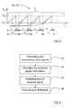
- a transmitted chirp signal 4a, 4b is in the form of a continuous sinusoid where the output frequency F out varies from a first frequency f start to a second frequency f stop over the course of a ramp r, where each chirp signal 4a, 4b comprises repeating cycles of a plurality of frequency ramps r. There the magnitude of the first frequency f start falls below the magnitude of the second frequency f stop .
- a cycle for a chirp signal 4a, 4b lasts for a certain cycle time t c , each ramp r lasts a certain ramp time t r , having a ramp period time t T . Between two consecutive ramps of the chirp signal 4a, 4b there is a delay time t D .
- the reflected signals 5a, 5b are received by the receiver 9 via the receiver antenna arrangement 16.
- the received signals 5a, 5b thus constituted by reflected radar echoes, are then mixed with the transmitted chirp signals 4a, 4b in the receiver 9.
- an IF (Intermediate Frequency) signal 17 is acquired and filtered in an IF filter 18 such that a filtered IF signal 19 is acquired.
- the difference frequency of the filtered IF signal 19 relates to the target distance and is transferred to the corresponding ADC arrangement 10, where the filtered IF signal 19 is sampled at a certain predetermined sampling frequency f s and converted to a digital IF signal 20, the sampling frequency f s being provided in the form of a sampling and timing signal 21 produced by the sampling and timing arrangement 11.
- the sampling and timing arrangement 11 is connected to a DSP arrangement 12 that is adapted for radar signal processing by means of a first FFT (Fast Fourier Transform) to convert the digital IF signals 20 to a range domain, and a second FFT to combine the results from successive chirp signal ramps into the Doppler domain.
- FFT Fast Fourier Transform
- a corresponding first received signal 5a and corresponding first received signal information 20a, 28a is obtained, and for a following second chirp signal cycle 4b, a corresponding second received signal 5b and corresponding second received signal information 20b, 28b is obtained, where a control unit 24, 31 is arranged to calculate a difference between the first received signal information 20a, 28a and the second received signal information 20b, 28b.
- resulting signal information 26, 27 is obtained, where close stationary objects 25 have been removed. This is due to the fact that between two such chirp signal cycles 4a, 4b, close stationary objects 25 tend to present a similar detected position, while more distant objects 6 present different detected positions due to the vehicle's movement as well as the more distant objects' movements if they are moving.
- the calculation of the difference between the first received signal information 20a and the second received signal information 20b is performed on the digital IF signals 20, where first received digital IF signals 20a for a first chirp signal cycle 4a are stored into a first memory 22 and second received digital IF signals 20b for a second chirp signal cycle 4b are stored into a second memory 23.
- a control unit 24 is arranged to calculate a difference between the first received digital IF signals 20a and the second received digital IF signals 20b, and to forward the resulting signal information 26 to the DSP arrangement 12.
- the vehicle radar system 3' comprises a transceiver arrangement 7' where the calculation of the difference between the first received signal information 28a and the second received signal information 28b is performed on an output 28 of the DSP arrangement 12, where this output comprises Range-Doppler matrices as described previously with reference to Figure 2 .
- a first output 28a of the DSP arrangement 12 for a first chirp signal cycle 4a is stored into a first memory 29 and a second output 28b of the DSP arrangement 12 for a second chirp signal cycle 4b is stored into a second memory 30.
- a control unit 31 is arranged to calculate a difference between the first output 28a and the second output 28b, and to forward the resulting signal information 27 for further handling.
- the received signal information 20a, 20b is in the form of digital IF signals
- the received signal information 28a, 28b is in the form of DSP output comprising Range-Doppler matrices. Normally, each chirp signal cycle results in a Range-Doppler matrix.
- the resulting signal information 26 comprises a difference between two different digital IF signals 20a, 20b
- the resulting signal information 27 comprises a difference between two different DSP outputs 28a, 28b.
- the first example discloses calculation of a difference between the rawest data available without any additional effects, for example scalloping losses from the FFT.
- the second example discloses calculation of a difference between data obtained after a spectral analysis, which reduces the required size of the memories 22, 23; 29, 30 since after the spectral analysis, it is not necessary to consider all data but only data from the range of interest.
- the range of interest is only a small section of the overall range, for example in the magnitude of 2 meters out of 100 meters.
- the vehicle 1 comprises a safety control unit 35 and safety means 36, for example an emergency braking system and/or an alarm signal device.
- the safety control unit 35 is arranged to control the safety means 36 in dependence of input from the radar system 3.
- the present disclosure relates to a method, where the method comprises:
- the method further comprises:
- the method further comprises:
- the method comprises:
- the present disclosure is not limited to the examples above, but may vary freely within the scope of the appended claims.
- the chirp signal ramps shown is only an example; they may for example be configured as up-ramp as described, or as down-ramps, or some combination of both. There may not be any delay time t D between consecutive ramps.
- the calculation does not have to be performed by a separate control unit, but may be performed by the DSP arrangement 12 itself, or by any other kind of combined control unit. In the first example, this means that the resulting signal information 26 is forwarded within the DSP arrangement 12.
- the vehicle radar system 3, 3' is arranged to calculate a difference between the first received signal information 20a, 28a and the second received signal information 20b, 28b.
- the memories may for example be part of a larger common memory unit, the DSP arrangement 12 or one or more control units.
- the received signal information may be directed to one common memory unit by one common connection and not divided to two different memories as shown in Figure 2 and Figure 3 .
- the embodiment with separate memories 22, 23; 29, 30 and a separate control unit 24, 31 is used in the examples to enhance the understanding of the present disclosure
- the radar system may be implemented in any type of vehicle such as cars, trucks and buses as well as boats and aircraft.
- Each antenna arrangement 14, 16 may for example comprise one or more antennas, and each antenna may be constituted by one antenna element or by an array of antenna elements.
- each ADC arrangement and the DSP arrangement should each one be interpreted as having a corresponding ADC or DSP functionality, and may each be constituted by a plurality of separate components.
- each ADC arrangement may be comprised in one ADC chip, and each DSP arrangement may be comprised in one DSP chip.
- the following second chirp signal cycle 4b may follow directly after the first chirp signal cycle 4a, or after a certain delay time or after one or more intermediate chirp signal cycles.
- any suitable radar signal is possible, for example pulsed radar, FSK (Frequency Shift Keying), stepped frequency, BPSK (Binary Phase Shift Keying) etc.
- the radar signal used should however be run in at least two cycles such that the difference between the corresponding received signal information 20a, 28a; 20b, 28b may be calculated.
- the present disclosure relates to a vehicle radar system 3, 3' comprising a transceiver arrangement 7, 7' that is arranged to generate and transmit at least a first radar signal cycle 4a and a following second radar signal cycle 4b, where, for the first radar signal cycle 4a, a corresponding first received signal 5a and corresponding first received signal information 20a, 28a is obtained, and for a following second radar signal cycle 4b, a corresponding second received signal 5b and corresponding second received signal information 20b, 28b is obtained.
- the vehicle radar system 3, 3' is arranged to calculate a difference between the first received signal information 20a, 28a and the second received signal information 20b, 28b.
- the vehicle radar system 3, 3' is arranged to:
- the first received signal information 20a is constituted by received digital IF signals 20a for a first radar signal cycle 4a and that the second received signal information 20b is constituted by received digital IF signals 20b for a second radar signal cycle 4b.
- the vehicle radar system 3, 3' is arranged to:
- the first received signal information 20a is constituted by an output 28a of a DSP (Digital Signal Processing) arrangement 12 for a first radar signal cycle 4a and that the second received signal information 20b is constituted by an output 28b of the DSP arrangement 12 for a second radar signal cycle 4b, where the output 28a, 28b of the DSP arrangement 12 comprises Range-Doppler matrices.
- DSP Digital Signal Processing
- the vehicle radar system 3, 3' is arranged to:
- each radar signal cycle 4a, 4b comprises an FMCW, Frequency Modulated Continuous Wave, chirp signal cycle 4a, 4b, where each chirp signal cycle 4a, 4b comprises a corresponding plurality of frequency ramps r, and where each frequency ramp r is arranged to run between a first frequency f start and a second frequency f stop .
- the present disclosure also relates to a method for a vehicle radar system 3, 3', where the method comprises:
- the method further comprises:
- the first received signal information 20a is constituted by received digital IF signals 20a for a first radar signal cycle 4a and that the second received signal information 20b is constituted by received digital IF signals 20b for a second radar signal cycle 4b.
- the method comprises:
- the first received signal information 20a is constituted by an output 28a of a DSP, Digital Signal Processing, arrangement 12 for a first radar signal cycle 4a and that the second received signal information 20b is constituted by an output 28b of the DSP arrangement 12 for a second radar signal cycle 4b, where the output 28a, 28b of the DSP arrangement 12 comprises Range-Doppler matrices.
- the method comprises:
- each radar signal cycle 4a, 4b uses an FMCW (Frequency Modulated Continuous Wave) chirp signal cycle 4a, 4b, where each chirp signal cycle 4a, 4b has a corresponding plurality of frequency ramps r, and where each frequency ramp r is intended to run between a first frequency f start and a second frequency f stop .
- FMCW Frequency Modulated Continuous Wave
Landscapes
- Engineering & Computer Science (AREA)
- Radar, Positioning & Navigation (AREA)
- Remote Sensing (AREA)
- Physics & Mathematics (AREA)
- Computer Networks & Wireless Communication (AREA)
- General Physics & Mathematics (AREA)
- Electromagnetism (AREA)
- Radar Systems Or Details Thereof (AREA)
Abstract
Description
- The present disclosure relates to a vehicle radar system comprising a transceiver arrangement that is arranged to generate and transmit at least a first radar signal cycle and a following second radar signal cycle. For the first radar signal cycle, a corresponding first received signal and corresponding first received signal information is obtained, and for a following second radar signal cycle, a corresponding second received signal and corresponding second received signal information is obtained.
- Many vehicle radar systems comprise radar transceivers that are arranged for generating radar signals, for example so-called chirp signals that are transmitted, reflected and received by means of appropriate antennas comprised in the radar system. A chirp signal is an FMCW (Frequency Modulated Continuous Wave) signal with a certain amplitude where the frequency is continuously ramped between two values, the chirp signal thus being in the form of a continuous sinusoid where the frequency varies from a first low frequency to a second high frequency over the course of the ramp. Alternatively the ramp may be such that the frequency varies from a first high frequency to a second low frequency. The magnitude of the change in frequency from start to finish may for example be of the order of 0.5% of the starting frequency.
- The received signals, thus constituted by reflected radar echoes, are mixed with the transmitted chirp signal in order to convert the received signals to baseband signals. These baseband signals, or IF (Intermediate Frequency) signals, are amplified and transferred in a plurality of channels to an Analog Digital Converter (ADC) arrangement which is arranged to convert the received analog signals to digital signals. The digital signals are used for retrieving an azimuth angle of possible targets by simultaneously sampling and analyzing phase and amplitude of the received signals. The analysis is generally performed in one or more Digital Signal Processors (DSP:s) by means of Fast Fourier Transform (FFT) processing.
- The radar signals are transmitted at a wavelength having a magnitude of for example one or a few centimeters, which is advantageous in order to be able to effectively avoid collisions. This also enables detection of objects that are close to the vehicle where a radar system is used. Due to reflections and multipath due to the vehicle itself, as well as collected dirt and similar, internal coupling of signals within the radar system, stationary objects that are close to the vehicle are detected and processed, which is disadvantageous since it these objects constitute unimportant detection and causes unnecessary data processing and can cause false association with a real desired object detection. These undesired detections cannot be distinguished from desired detections from close real objects.
- The object of the present disclosure is thus to provide a vehicle radar system where such close stationary objects are removed at an early stage, avoiding the above disadvantages.
- This object is achieved by means of a vehicle radar system comprising a vehicle radar system comprising a transceiver arrangement that is arranged to generate and transmit at least a first radar signal cycle and a following second radar signal cycle. For the first radar signal cycle, a corresponding first received signal and corresponding first received signal information is obtained, and for a following second radar signal cycle, a corresponding second received signal and corresponding second received signal information is obtained. Furthermore, the vehicle radar system is arranged to calculate a difference between the first received signal information and the second received signal information.
- This object is also achieved by means of a method for a vehicle radar system, where the method comprises:
- Generating and transmitting at least a first radar signal cycle and a following second radar signal cycle.
- Obtaining a corresponding first received signal and corresponding first received signal information for the first radar signal cycle.
- Obtaining a corresponding second received signal and corresponding second received signal information for the following second radar signal cycle.
- Calculating a difference between the first received signal information and the second received signal information.
- According to an example, the vehicle radar system is arranged to:
- Mix and filter the received signals with respective transmitted radar signals to obtain at least one filtered IF (Intermediate Frequency) signal.
- Convert said filtered IF signals to digital IF signals.
- Convert the digital IF signals to a range domain by means of a first FFT (Fast Fourier Transform).
- Combine the results from successive radar signal cycles into the Doppler domain by means of a second FFT, such that a plurality of corresponding Range-Doppler matrices is obtained.
- According to another example, the first received signal information is constituted by received digital IF signals for a first radar signal cycle and that the second received signal information is constituted by received digital IF signals for a second radar signal cycle.
- According to another example, the vehicle radar system is arranged to:
- Store first received digital IF signals for a first radar signal cycle and second received digital IF signals for a second radar signal cycle.
- Calculate a difference between the first received digital IF signals and the second received digital IF signals.
- Forward resulting signal information to a DSP arrangement.
- According to another example, the first received signal information is constituted by an output of a DSP arrangement for a first radar signal cycle. Furthermore, the second received signal information is constituted by an output of the DSP arrangement for a second radar signal cycle. The output of the DSP arrangement comprises Range-Doppler matrices.
- According to another example, the vehicle radar system is arranged to:
- Store a first output of the DSP arrangement for a first radar signal cycle and a second output of the DSP arrangement for a second radar signal cycle.
- Calculate a difference between the first output and the second output information.
- Forward resulting signal information for further handling.
- According to another example, each radar signal cycle comprises an FMCW chirp signal cycle, where each chirp signal cycle comprises a corresponding plurality of frequency ramps. Each frequency ramp is arranged to run between a first frequency and a second frequency.
- Other examples are disclosed in the dependent claims.
- A number of advantages are obtained by means of the present disclosure. Mainly, a vehicle radar system is provided where close stationary objects are discarded in a reliable an uncomplicated manner.
- The present disclosure will now be described more in detail with reference to the appended drawings, where:
- Figure 1
- shows a schematic top view of a vehicle;
- Figure 2
- shows a simplified schematic of a vehicle radar system according to a first example;
- Figure 3
- shows a simplified schematic of a vehicle radar system according to a second example;
- Figure 4
- shows a chirp signal;
- Figure 5
- shows a flowchart for a method according to the present disclosure; and
- Figure 6
- shows a flowchart illustrating examples of methods according to the present disclosure
-
Figure 1 schematically shows a top view of avehicle 1 arranged to run on aroad 2 in a direction D, where thevehicle 1 comprises avehicle radar system 3 which is arranged to distinguish and/or resolve single targets from the surroundings by transmittingsignals reflected signals vehicle radar system 3 is arranged to provide azimuth angles ofpossible objects signals distant object 6 that may be moving and a closestationary object 25. The closestationary object 25 may be due to reflections and multipath due to thevehicle 1 itself, as well as collected dirt and/or similar. - With reference also to
Figure 2 , thevehicle radar system 3 comprises atransceiver arrangement 7 that is arranged for generating and transmitting sweep signals in the form of FMCW (Frequency Modulated Continuous Wave)chirp signals reflected signals chirp signals object 6. - The
transceiver arrangement 7 comprises atransmitter 8 with a transmitantenna arrangement 14, areceiver 9 with areceiver antenna arrangement 16, an Analog to Digital Converter (ADC)arrangement 10 and sampling andtiming arrangement 11. - As shown in
Figure 3 , a transmittedchirp signal chirp signal - A cycle for a
chirp signal chirp signal - Referring back to
Figure 2 , the reflectedsignals receiver 9 via thereceiver antenna arrangement 16. The received signals 5a, 5b, thus constituted by reflected radar echoes, are then mixed with the transmittedchirp signals receiver 9. - In this way, an IF (Intermediate Frequency) signal 17 is acquired and filtered in an
IF filter 18 such that a filtered IFsignal 19 is acquired. - The difference frequency of the filtered IF
signal 19 relates to the target distance and is transferred to thecorresponding ADC arrangement 10, where the filtered IFsignal 19 is sampled at a certain predetermined sampling frequency fs and converted to a digital IFsignal 20, the sampling frequency fs being provided in the form of a sampling andtiming signal 21 produced by the sampling andtiming arrangement 11. - The sampling and
timing arrangement 11 is connected to aDSP arrangement 12 that is adapted for radar signal processing by means of a first FFT (Fast Fourier Transform) to convert the digital IF signals 20 to a range domain, and a second FFT to combine the results from successive chirp signal ramps into the Doppler domain. This results in anoutput 32 comprising Range-Doppler matrices that are transferred for further processing, which is not further discussed here, many examples of such further processing being well-known in the art. According to the present disclosure, with reference toFigure 2 andFigure 3 , for a firstchirp signal cycle 4a, a corresponding first receivedsignal 5a and corresponding first receivedsignal information chirp signal cycle 4b, a corresponding second receivedsignal 5b and corresponding second receivedsignal information control unit signal information signal information - By means of this calculation, resulting
signal information stationary objects 25 have been removed. This is due to the fact that between two suchchirp signal cycles stationary objects 25 tend to present a similar detected position, while moredistant objects 6 present different detected positions due to the vehicle's movement as well as the more distant objects' movements if they are moving. - In the following, two different examples presenting two different kinds of received
signal information signal information - According to a first example, with reference to
Figure 2 , the calculation of the difference between the first receivedsignal information 20a and the second receivedsignal information 20b is performed on the digital IF signals 20, where first received digital IF signals 20a for a firstchirp signal cycle 4a are stored into afirst memory 22 and second received digital IF signals 20b for a secondchirp signal cycle 4b are stored into asecond memory 23. Acontrol unit 24 is arranged to calculate a difference between the first received digital IF signals 20a and the second received digital IFsignals 20b, and to forward the resultingsignal information 26 to theDSP arrangement 12. - According to a second example, with reference to
Figure 3 , the vehicle radar system 3' comprises a transceiver arrangement 7' where the calculation of the difference between the first receivedsignal information 28a and the second receivedsignal information 28b is performed on anoutput 28 of theDSP arrangement 12, where this output comprises Range-Doppler matrices as described previously with reference toFigure 2 . Afirst output 28a of theDSP arrangement 12 for a firstchirp signal cycle 4a is stored into afirst memory 29 and asecond output 28b of theDSP arrangement 12 for a secondchirp signal cycle 4b is stored into asecond memory 30. Acontrol unit 31 is arranged to calculate a difference between thefirst output 28a and thesecond output 28b, and to forward the resultingsignal information 27 for further handling. - This means that in the first example the received
signal information signal information signal information 26 comprises a difference between two different digital IFsignals signal information 27 comprises a difference between twodifferent DSP outputs - From a signal processing point of view, the first example discloses calculation of a difference between the rawest data available without any additional effects, for example scalloping losses from the FFT.
- The second example discloses calculation of a difference between data obtained after a spectral analysis, which reduces the required size of the
memories - As indicated in
Figure 1 , thevehicle 1 comprises asafety control unit 35 and safety means 36, for example an emergency braking system and/or an alarm signal device. Thesafety control unit 35 is arranged to control the safety means 36 in dependence of input from theradar system 3. - With reference to
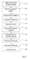
Figure 5 , the present disclosure relates to a method, where the method comprises: - 33: Generating and transmitting at least a first
radar signal cycle 4a and a following secondradar signal cycle 4b; - 34: Obtaining a corresponding first received
signal 5a and corresponding first receivedsignal information radar signal cycle 4a. - 35: Obtaining a corresponding second received
signal 5b and corresponding second receivedsignal information radar signal cycle 4b. - 36: Calculating a difference between the first received
signal information signal information - With reference to
Figure 6 , according to an example, the method further comprises: - 37: Mixing and filtering the received
signals radar signals signal 19. - 38: Converting said filtered IF
signals - 39: Converting the digital IF signals 20 to a range domain by means of a first FFT (Fast Fourier Transform).
- 40: Combining the results from successive radar signal cycles into the Doppler domain by means of a second FFT, such that a plurality of corresponding Range-Doppler matrices is obtained.
- According to another example, the method further comprises:
- 41: Storing first received digital IF signals 20a for a first
radar signal cycle 4a and second received digital IF signals 20b for a secondradar signal cycle 4b. - 42: Calculating a difference between the first received digital IF signals 20a and the second received digital IF
signals 20b. - 43: Forwarding resulting
signal information 26 to aDSP arrangement 12. - According to another alternative example, the method comprises:
- 44: Storing a
first output 28a of theDSP arrangement 12 for a firstradar signal cycle 4a and asecond output 28b of theDSP arrangement 12 for a secondradar signal cycle 4b. - 45: Calculating a difference between the
first output 28a and thesecond output information 28b. - 46: Forwarding resulting
signal information 27 for further handling. - The present disclosure is not limited to the examples above, but may vary freely within the scope of the appended claims. For example, the chirp signal ramps shown is only an example; they may for example be configured as up-ramp as described, or as down-ramps, or some combination of both. There may not be any delay time tD between consecutive ramps.
- The calculation does not have to be performed by a separate control unit, but may be performed by the
DSP arrangement 12 itself, or by any other kind of combined control unit. In the first example, this means that the resultingsignal information 26 is forwarded within theDSP arrangement 12. - Generally, the
vehicle radar system 3, 3' is arranged to calculate a difference between the first receivedsignal information signal information - The memories may for example be part of a larger common memory unit, the
DSP arrangement 12 or one or more control units. The received signal information may be directed to one common memory unit by one common connection and not divided to two different memories as shown inFigure 2 andFigure 3 . The embodiment withseparate memories separate control unit - The radar system may be implemented in any type of vehicle such as cars, trucks and buses as well as boats and aircraft.
- The schematics of vehicle radar systems are simplified, only showing parts that are considered relevant for an adequate description of the present disclosure. It is understood that the general design of radar systems of this kind is well-known in the art.
- The number of antenna arrangements, antennas within each antenna arrangement and IF signals may vary. Each
antenna arrangement - The ADC arrangement and the DSP arrangement should each one be interpreted as having a corresponding ADC or DSP functionality, and may each be constituted by a plurality of separate components. Alternatively, each ADC arrangement may be comprised in one ADC chip, and each DSP arrangement may be comprised in one DSP chip.
- The following second
chirp signal cycle 4b may follow directly after the firstchirp signal cycle 4a, or after a certain delay time or after one or more intermediate chirp signal cycles. - Although the above description has been directed towards FMCW, any suitable radar signal is possible, for example pulsed radar, FSK (Frequency Shift Keying), stepped frequency, BPSK (Binary Phase Shift Keying) etc. The radar signal used should however be run in at least two cycles such that the difference between the corresponding received
signal information - Generally, the present disclosure relates to a
vehicle radar system 3, 3' comprising atransceiver arrangement 7, 7' that is arranged to generate and transmit at least a firstradar signal cycle 4a and a following secondradar signal cycle 4b, where, for the firstradar signal cycle 4a, a corresponding first receivedsignal 5a and corresponding first receivedsignal information radar signal cycle 4b, a corresponding second receivedsignal 5b and corresponding second receivedsignal information vehicle radar system 3, 3' is arranged to calculate a difference between the first receivedsignal information signal information - According to an example, the
vehicle radar system 3, 3' is arranged to: - mix and filter the received
signals radar signals signal 19; - convert said filtered IF
signals - convert the digital IF signals 20 to a range domain by means of a first FFT (Fast Fourier Transform); and to
- combine the results from successive radar signal cycles into the Doppler domain by means of a second FFT, such that a plurality of corresponding Range-Doppler matrices is obtained.
- According to an example, the first received
signal information 20a is constituted by received digital IF signals 20a for a firstradar signal cycle 4a and that the second receivedsignal information 20b is constituted by received digital IF signals 20b for a secondradar signal cycle 4b. - According to an example, the
vehicle radar system 3, 3' is arranged to: - store first received digital IF signals 20a for a first
radar signal cycle 4a and second received digital IF signals 20b for a secondradar signal cycle 4b, - calculate a difference between the first received digital IF signals 20a and the second received digital IF
signals 20b, and to - forward resulting
signal information 26 to a DSP (Digital Signal Processing)arrangement 12. - According to an example, the first received
signal information 20a is constituted by anoutput 28a of a DSP (Digital Signal Processing)arrangement 12 for a firstradar signal cycle 4a and that the second receivedsignal information 20b is constituted by anoutput 28b of theDSP arrangement 12 for a secondradar signal cycle 4b, where theoutput DSP arrangement 12 comprises Range-Doppler matrices. - According to an example, the
vehicle radar system 3, 3' is arranged to: - store a
first output 28a of theDSP arrangement 12 for a firstradar signal cycle 4a and asecond output 28b of theDSP arrangement 12 for a secondradar signal cycle 4b; - calculate a difference between the
first output 28a and thesecond output information 28b, and to - forward resulting
signal information 27 for further handling. - According to an example, each
radar signal cycle chirp signal cycle chirp signal cycle - Generally, the present disclosure also relates to a method for a
vehicle radar system 3, 3', where the method comprises: - 33: generating and transmitting at least a first
radar signal cycle 4a and a following secondradar signal cycle 4b; - 34: obtaining a corresponding first received
signal 5a and corresponding first receivedsignal information radar signal cycle 4a; and - 35: obtaining a corresponding second received
signal 5b and corresponding second receivedsignal information radar signal cycle 4b; and - 36: calculating a difference between the first received
signal information signal information - According to an example, the method further comprises:
- 37: mixing and filtering the received
signals radar signals signal 19; - 38: converting said filtered IF
signals - 39: converting the digital IF signals 20 to a range domain by means of a first FFT (Fast Fourier Transform); and
- 40: combining the results from successive radar signal cycles into the Doppler domain by means of a second FFT, such that a plurality of corresponding Range-Doppler matrices is obtained.
- According to an example, the first received
signal information 20a is constituted by received digital IF signals 20a for a firstradar signal cycle 4a and that the second receivedsignal information 20b is constituted by received digital IF signals 20b for a secondradar signal cycle 4b. - According to an example, the method comprises:
- 41: storing first received digital IF signals 20a for a first
radar signal cycle 4a and second received digital IF signals 20b for a secondradar signal cycle 4b; - 42: calculating a difference between the first received digital IF signals 20a and the second received digital IF
signals 20b; and - 43: forwarding resulting
signal information 26 to a DSP (Digital Signal Processing)arrangement 12. - According to an example, the first received
signal information 20a is constituted by anoutput 28a of a DSP, Digital Signal Processing,arrangement 12 for a firstradar signal cycle 4a and that the second receivedsignal information 20b is constituted by anoutput 28b of theDSP arrangement 12 for a secondradar signal cycle 4b, where theoutput DSP arrangement 12 comprises Range-Doppler matrices. - According to an example, the method comprises:
- 44: storing a
first output 28a of theDSP arrangement 12 for a firstradar signal cycle 4a and asecond output 28b of theDSP arrangement 12 for a secondradar signal cycle 4b; - 45: calculating a difference between the
first output 28a and thesecond output information 28b; and - 46: forwarding resulting
signal information 27 for further handling. - According to an example, each
radar signal cycle chirp signal cycle chirp signal cycle
Claims (14)
- A vehicle radar system (3, 3') comprising a transceiver arrangement (7, 7') that is arranged to generate and transmit at least a first radar signal cycle (4a) and a following second radar signal cycle (4b), where, for the first radar signal cycle (4a), a corresponding first received signal (5a) and corresponding first received signal information (20a, 28a) is obtained, and for a following second radar signal cycle (4b), a corresponding second received signal (5b) and corresponding second received signal information (20b, 28b) is obtained, characterized in that the vehicle radar system (3, 3') is arranged to calculate a difference between the first received signal information (20a, 28a) and the second received signal information (20b, 28b).
- The vehicle radar system (3, 3') according to claim 1, characterized in that the vehicle radar system (3, 3') is arranged to:- mix and filter the received signals (5a, 5b) with respective transmitted radar signals (4a, 4b) to obtain at least one filtered IF, Intermediate Frequency, signal (19) ;- convert said filtered IF signals (17, 19) to digital IF signals (20);- convert the digital IF signals (20) to a range domain by means of a first FFT, Fast Fourier Transform; and to- combine the results from successive radar signal cycles into the Doppler domain by means of a second FFT, such that a plurality of corresponding Range-Doppler matrices is obtained.
- The vehicle radar system (3, 3') according to claim 2, characterized in that the first received signal information (20a) is constituted by received digital IF signals (20a) for a first radar signal cycle (4a) and that the second received signal information (20b) is constituted by received digital IF signals (20b) for a second radar signal cycle (4b).
- The vehicle radar system (3, 3') according to claim 3, characterized in that the vehicle radar system (3, 3') is arranged to:- store first received digital IF signals (20a) for a first radar signal cycle (4a) and second received digital IF signals (20b) for a second radar signal cycle (4b),- calculate a difference between the first received digital IF signals (20a) and the second received digital IF signals (20b), and to- forward resulting signal information (26) to a DSP, Digital Signal Processing, arrangement (12).
- The vehicle radar system (3, 3') according to claim 2, characterized in that the first received signal information (20a) is constituted by an output (28a) of a DSP, Digital Signal Processing, arrangement (12) for a first radar signal cycle (4a) and that the second received signal information (20b) is constituted by an output (28b) of the DSP arrangement (12) for a second radar signal cycle (4b), where the output (28a, 28b) of the DSP arrangement (12) comprises Range-Doppler matrices.
- The vehicle radar system (3, 3') according to claim 5, characterized in that the vehicle radar system (3, 3') is arranged to:- store a first output (28a) of the DSP arrangement (12) for a first radar signal cycle (4a) and a second output (28b) of the DSP arrangement (12) for a second radar signal cycle (4b);- calculate a difference between the first output (28a) and the second output information (28b), and to- forward resulting signal information (27) for further handling.
- The vehicle radar system (3, 3') according to any one of the previous claims, characterized in that each radar signal cycle (4a, 4b) comprises an FMCW, Frequency Modulated Continuous Wave, chirp signal cycle (4a, 4b), where each chirp signal cycle (4a, 4b) comprises a corresponding plurality of frequency ramps (r), and where each frequency ramp (r) is arranged to run between a first frequency (fstart) and a second frequency (fstop).
- A method for a vehicle radar system (3, 3'), where the method comprises:(33) generating and transmitting at least a first radar signal cycle (4a) and a following second radar signal cycle (4b);(34) obtaining a corresponding first received signal (5a) and corresponding first received signal information (20a, 28a) for the first radar signal cycle (4a); and(35) obtaining a corresponding second received signal (5b) and corresponding second received signal information (20b, 28b) for the following second radar signal cycle (4b), characterized in that the method further comprises:(36) calculating a difference between the first received signal information (20a, 28a) and the second received signal information (20b, 28b).
- The method according to claim 8, characterized in that the method further comprises:(37) mixing and filtering the received signals (5a, 5b) with respective transmitted radar signals (4a, 4b) to obtain at least one filtered IF, Intermediate Frequency, signal (19);(38) converting said filtered IF signals (17, 19) to digital IF signals (20);(39) converting the digital IF signals (20) to a range domain by means of a first FFT, Fast Fourier Transform; and(40) combining the results from successive radar signal cycles into the Doppler domain by means of a second FFT, such that a plurality of corresponding Range-Doppler matrices is obtained.
- The method according to claim 9, characterized in that the first received signal information (20a) is constituted by received digital IF signals (20a) for a first radar signal cycle (4a) and that the second received signal information (20b) is constituted by received digital IF signals (20b) for a second radar signal cycle (4b).
- The method according to claim 10, characterized in that the method comprises:(41) storing first received digital IF signals (20a) for a first radar signal cycle (4a) and second received digital IF signals (20b) for a second radar signal cycle (4b);(42) calculating a difference between the first received digital IF signals (20a) and the second received digital IF signals (20b); and(43) forwarding resulting signal information (26) to a DSP, Digital Signal Processing, arrangement (12).
- The method according to claim 9, characterized in that the first received signal information (20a) is constituted by an output (28a) of a DSP, Digital Signal Processing, arrangement (12) for a first radar signal cycle (4a) and that the second received signal information (20b) is constituted by an output (28b) of the DSP arrangement (12) for a second radar signal cycle (4b), where the output (28a, 28b) of the DSP arrangement (12) comprises Range-Doppler matrices.
- The method according to claim 12, characterized in that the method comprises:(44) storing a first output (28a) of the DSP arrangement (12) for a first radar signal cycle (4a) and a second output (28b) of the DSP arrangement (12) for a second radar signal cycle (4b);(45) calculating a difference between the first output (28a) and the second output information (28b); and(46) forwarding resulting signal information (27) for further handling.
- The method according to any one of the claims 8-13, characterized in that each radar signal cycle (4a, 4b) uses an FMCW, Frequency Modulated Continuous Wave, chirp signal cycle (4a, 4b), where each chirp signal cycle (4a, 4b) has a corresponding plurality of frequency ramps (r), and where each frequency ramp (r) is intended to run between a first frequency (fstart) and a second frequency (fstop).
Priority Applications (4)
| Application Number | Priority Date | Filing Date | Title |
|---|---|---|---|
| EP15183546.9A EP3139194B1 (en) | 2015-09-02 | 2015-09-02 | A close range filtering fmcw radar |
| US15/756,838 US10816660B2 (en) | 2015-09-02 | 2016-08-31 | Close range filtering vehicle radar |
| PCT/EP2016/070485 WO2017037100A1 (en) | 2015-09-02 | 2016-08-31 | A close range filtering vehicle radar |
| CN201680050669.9A CN107923966B (en) | 2015-09-02 | 2016-08-31 | Short-distance filtering vehicle radar |
Applications Claiming Priority (1)
| Application Number | Priority Date | Filing Date | Title |
|---|---|---|---|
| EP15183546.9A EP3139194B1 (en) | 2015-09-02 | 2015-09-02 | A close range filtering fmcw radar |
Publications (2)
| Publication Number | Publication Date |
|---|---|
| EP3139194A1 true EP3139194A1 (en) | 2017-03-08 |
| EP3139194B1 EP3139194B1 (en) | 2022-04-20 |
Family
ID=54056130
Family Applications (1)
| Application Number | Title | Priority Date | Filing Date |
|---|---|---|---|
| EP15183546.9A Active EP3139194B1 (en) | 2015-09-02 | 2015-09-02 | A close range filtering fmcw radar |
Country Status (4)
| Country | Link |
|---|---|
| US (1) | US10816660B2 (en) |
| EP (1) | EP3139194B1 (en) |
| CN (1) | CN107923966B (en) |
| WO (1) | WO2017037100A1 (en) |
Families Citing this family (4)
| Publication number | Priority date | Publication date | Assignee | Title |
|---|---|---|---|---|
| US10061015B2 (en) * | 2015-09-30 | 2018-08-28 | Texas Instruments Incorporated | Multi-chip transceiver testing in a radar system |
| US10775489B2 (en) * | 2016-12-15 | 2020-09-15 | Texas Instruments Incorporated | Maximum measurable velocity in frequency modulated continuous wave (FMCW) radar |
| CN110531358B (en) * | 2018-05-25 | 2023-07-18 | 华为技术有限公司 | Information measuring method and information measuring device |
| CN113541727B (en) * | 2020-03-31 | 2023-04-28 | 华为云计算技术有限公司 | Millimeter wave radar communication method, device and readable storage medium |
Citations (3)
| Publication number | Priority date | Publication date | Assignee | Title |
|---|---|---|---|---|
| WO2004029650A1 (en) * | 2002-09-20 | 2004-04-08 | Robert Bosch Gmbh | Method for measuring distances and speeds of several objects by means of an fmcw radar |
| WO2005124391A1 (en) * | 2004-06-22 | 2005-12-29 | Robert Bosch Gmbh | Radar sensor and process for evaluating objects |
| WO2014123112A1 (en) * | 2013-02-05 | 2014-08-14 | 株式会社デンソー | Device and method for detecting target in periphery of vehicle |
Family Cites Families (16)
| Publication number | Priority date | Publication date | Assignee | Title |
|---|---|---|---|---|
| US6400306B1 (en) * | 1999-12-17 | 2002-06-04 | Sicom Systems, Ltd | Multi-channel moving target radar detection and imaging apparatus and method |
| US7167126B2 (en) * | 2004-09-01 | 2007-01-23 | The Boeing Company | Radar system and method for determining the height of an object |
| US7924218B2 (en) * | 2004-09-03 | 2011-04-12 | American Systems Corp. | System for enhanced detection of a target |
| IL175465A (en) * | 2005-10-19 | 2013-02-28 | Elta Systems Ltd | Pulse doppler coherent method and system for snr enhancement |
| US7791528B2 (en) * | 2008-11-24 | 2010-09-07 | Autoliv Asp, Inc. | Method and apparatus for radar signal processing |
| JP4790045B2 (en) * | 2009-05-19 | 2011-10-12 | 本田技研工業株式会社 | Device for determining radar axis misalignment |
| CN102288942B (en) * | 2011-06-24 | 2013-05-08 | 北京理工大学 | A Design Method of Millimeter Wave Radar Signal Waveform |
| US8866667B2 (en) * | 2012-02-22 | 2014-10-21 | Honeywell International Inc. | High sensitivity single antenna FMCW radar |
| CN102608606A (en) * | 2012-03-22 | 2012-07-25 | 河海大学 | Effective method for accurately detecting multiple targets by automobile blind zone monitoring radar |
| CN102707266B (en) * | 2012-05-24 | 2014-06-04 | 北京理工大学 | Radar with anti-interference and multi-target identification functions and detection method thereof |
| CN102798863B (en) * | 2012-07-04 | 2014-06-18 | 西安电子科技大学 | Road central isolation belt detection method based on automobile anti-collision radar |
| CN103852756B (en) * | 2012-11-30 | 2017-02-22 | 中国科学院沈阳自动化研究所 | Target detecting and tracking method by utilization of continuous wave radar |
| CN103257346B (en) * | 2013-05-15 | 2014-12-10 | 桂林电子科技大学 | Automotive anti-collision radar multi-target detecting method and system |
| US9678197B2 (en) * | 2013-09-26 | 2017-06-13 | Honeywell International Inc. | FMCW radar with refined measurement using fixed frequencies |
| KR101896726B1 (en) * | 2013-12-02 | 2018-09-07 | 주식회사 만도 | Method and apparatus for detecting surrounding environment based on sensing signal of frequency modulated continuous wave radar and continuous wave radar |
| KR20150134126A (en) * | 2014-05-21 | 2015-12-01 | 재단법인대구경북과학기술원 | Method and apparatus for processing radar signal |
-
2015
- 2015-09-02 EP EP15183546.9A patent/EP3139194B1/en active Active
-
2016
- 2016-08-31 CN CN201680050669.9A patent/CN107923966B/en active Active
- 2016-08-31 US US15/756,838 patent/US10816660B2/en active Active
- 2016-08-31 WO PCT/EP2016/070485 patent/WO2017037100A1/en not_active Ceased
Patent Citations (4)
| Publication number | Priority date | Publication date | Assignee | Title |
|---|---|---|---|---|
| WO2004029650A1 (en) * | 2002-09-20 | 2004-04-08 | Robert Bosch Gmbh | Method for measuring distances and speeds of several objects by means of an fmcw radar |
| WO2005124391A1 (en) * | 2004-06-22 | 2005-12-29 | Robert Bosch Gmbh | Radar sensor and process for evaluating objects |
| WO2014123112A1 (en) * | 2013-02-05 | 2014-08-14 | 株式会社デンソー | Device and method for detecting target in periphery of vehicle |
| DE112014000682T5 (en) * | 2013-02-05 | 2015-10-29 | Denso Corporation | DEVICE AND METHOD FOR DETECTING A TARGET IN THE SURROUNDINGS OF A VEHICLE |
Also Published As
| Publication number | Publication date |
|---|---|
| EP3139194B1 (en) | 2022-04-20 |
| CN107923966A (en) | 2018-04-17 |
| US20180267164A1 (en) | 2018-09-20 |
| CN107923966B (en) | 2021-09-14 |
| US10816660B2 (en) | 2020-10-27 |
| WO2017037100A1 (en) | 2017-03-09 |
Similar Documents
| Publication | Publication Date | Title |
|---|---|---|
| US11693106B2 (en) | Multiple input multiple output (MIMO) frequency-modulated continuous-wave (FMCW) radar system | |
| EP3147685B1 (en) | A vehicle synthetic aperture radar system | |
| US10996311B2 (en) | Distributed radar sensor system | |
| US11215692B2 (en) | FMCW radar with additional AM for interference detection | |
| US11592520B2 (en) | FMCW radar with interfering signal suppression in the time domain | |
| US11762084B2 (en) | Vehicle radar system | |
| EP3244229A1 (en) | A vehicle radar system arranged for interference reduction | |
| EP3173812A1 (en) | A vehicle radar system arranged for reducing interference | |
| EP2876460B1 (en) | A vehicle radar with two transmitter antenna arrangements | |
| CN107683422A (en) | Vehicle radar system | |
| EP3264131A1 (en) | A vehicle radar for environmental detection | |
| EP3306339A1 (en) | A vehicle radar system arranged for interference reduction | |
| EP3460512B1 (en) | A vehicle radar for environmental detection | |
| EP3153875A1 (en) | A modular vehicle radar | |
| US12546888B2 (en) | Method and processor circuit for operating a radar system comprising multiple antennas, radar system and motor vehicle | |
| US10816660B2 (en) | Close range filtering vehicle radar | |
| CN102224432A (en) | Method and apparatus for radar signal processing | |
| EP3418768A1 (en) | A vehicle radar system comprising two radar sensor arrangements | |
| KR102132455B1 (en) | Active and Passive Complex Sensor That Operates in Frequency Division | |
| US9482744B1 (en) | Staggered pulse repetition frequency doppler processing | |
| WO2021166205A1 (en) | Radar device, method for detecting object of observation, and in-vehicle device | |
| EP3168637A1 (en) | A modular vehicle radar | |
| Rohling | From Huelsmeyer's telemobiloskop to the digital radar |
Legal Events
| Date | Code | Title | Description |
|---|---|---|---|
| PUAI | Public reference made under article 153(3) epc to a published international application that has entered the european phase |
Free format text: ORIGINAL CODE: 0009012 |
|
| STAA | Information on the status of an ep patent application or granted ep patent |
Free format text: STATUS: THE APPLICATION HAS BEEN PUBLISHED |
|
| AK | Designated contracting states |
Kind code of ref document: A1 Designated state(s): AL AT BE BG CH CY CZ DE DK EE ES FI FR GB GR HR HU IE IS IT LI LT LU LV MC MK MT NL NO PL PT RO RS SE SI SK SM TR |
|
| AX | Request for extension of the european patent |
Extension state: BA ME |
|
| STAA | Information on the status of an ep patent application or granted ep patent |
Free format text: STATUS: REQUEST FOR EXAMINATION WAS MADE |
|
| 17P | Request for examination filed |
Effective date: 20170831 |
|
| RBV | Designated contracting states (corrected) |
Designated state(s): AL AT BE BG CH CY CZ DE DK EE ES FI FR GB GR HR HU IE IS IT LI LT LU LV MC MK MT NL NO PL PT RO RS SE SI SK SM TR |
|
| RAP1 | Party data changed (applicant data changed or rights of an application transferred) |
Owner name: VEONEER SWEDEN AB |
|
| STAA | Information on the status of an ep patent application or granted ep patent |
Free format text: STATUS: EXAMINATION IS IN PROGRESS |
|
| 17Q | First examination report despatched |
Effective date: 20191016 |
|
| REG | Reference to a national code |
Ref country code: DE Ref legal event code: R079 Ref document number: 602015078317 Country of ref document: DE Free format text: PREVIOUS MAIN CLASS: G01S0007350000 Ipc: G01S0013931000 |
|
| GRAP | Despatch of communication of intention to grant a patent |
Free format text: ORIGINAL CODE: EPIDOSNIGR1 |
|
| STAA | Information on the status of an ep patent application or granted ep patent |
Free format text: STATUS: GRANT OF PATENT IS INTENDED |
|
| RIC1 | Information provided on ipc code assigned before grant |
Ipc: G01S 13/93 20200101ALI20211022BHEP Ipc: G01S 13/538 20060101ALI20211022BHEP Ipc: G01S 13/34 20060101ALI20211022BHEP Ipc: G01S 7/35 20060101ALI20211022BHEP Ipc: G01S 13/931 20200101AFI20211022BHEP |
|
| INTG | Intention to grant announced |
Effective date: 20211119 |
|
| GRAS | Grant fee paid |
Free format text: ORIGINAL CODE: EPIDOSNIGR3 |
|
| GRAA | (expected) grant |
Free format text: ORIGINAL CODE: 0009210 |
|
| STAA | Information on the status of an ep patent application or granted ep patent |
Free format text: STATUS: THE PATENT HAS BEEN GRANTED |
|
| AK | Designated contracting states |
Kind code of ref document: B1 Designated state(s): AL AT BE BG CH CY CZ DE DK EE ES FI FR GB GR HR HU IE IS IT LI LT LU LV MC MK MT NL NO PL PT RO RS SE SI SK SM TR |
|
| REG | Reference to a national code |
Ref country code: GB Ref legal event code: FG4D |
|
| REG | Reference to a national code |
Ref country code: CH Ref legal event code: EP |
|
| REG | Reference to a national code |
Ref country code: IE Ref legal event code: FG4D |
|
| REG | Reference to a national code |
Ref country code: DE Ref legal event code: R096 Ref document number: 602015078317 Country of ref document: DE |
|
| REG | Reference to a national code |
Ref country code: AT Ref legal event code: REF Ref document number: 1485577 Country of ref document: AT Kind code of ref document: T Effective date: 20220515 |
|
| REG | Reference to a national code |
Ref country code: SE Ref legal event code: TRGR |
|
| REG | Reference to a national code |
Ref country code: LT Ref legal event code: MG9D |
|
| REG | Reference to a national code |
Ref country code: NL Ref legal event code: MP Effective date: 20220420 |
|
| REG | Reference to a national code |
Ref country code: AT Ref legal event code: MK05 Ref document number: 1485577 Country of ref document: AT Kind code of ref document: T Effective date: 20220420 |
|
| PG25 | Lapsed in a contracting state [announced via postgrant information from national office to epo] |
Ref country code: NL Free format text: LAPSE BECAUSE OF FAILURE TO SUBMIT A TRANSLATION OF THE DESCRIPTION OR TO PAY THE FEE WITHIN THE PRESCRIBED TIME-LIMIT Effective date: 20220420 |
|
| PG25 | Lapsed in a contracting state [announced via postgrant information from national office to epo] |
Ref country code: PT Free format text: LAPSE BECAUSE OF FAILURE TO SUBMIT A TRANSLATION OF THE DESCRIPTION OR TO PAY THE FEE WITHIN THE PRESCRIBED TIME-LIMIT Effective date: 20220822 Ref country code: NO Free format text: LAPSE BECAUSE OF FAILURE TO SUBMIT A TRANSLATION OF THE DESCRIPTION OR TO PAY THE FEE WITHIN THE PRESCRIBED TIME-LIMIT Effective date: 20220720 Ref country code: LT Free format text: LAPSE BECAUSE OF FAILURE TO SUBMIT A TRANSLATION OF THE DESCRIPTION OR TO PAY THE FEE WITHIN THE PRESCRIBED TIME-LIMIT Effective date: 20220420 Ref country code: HR Free format text: LAPSE BECAUSE OF FAILURE TO SUBMIT A TRANSLATION OF THE DESCRIPTION OR TO PAY THE FEE WITHIN THE PRESCRIBED TIME-LIMIT Effective date: 20220420 Ref country code: GR Free format text: LAPSE BECAUSE OF FAILURE TO SUBMIT A TRANSLATION OF THE DESCRIPTION OR TO PAY THE FEE WITHIN THE PRESCRIBED TIME-LIMIT Effective date: 20220721 Ref country code: FI Free format text: LAPSE BECAUSE OF FAILURE TO SUBMIT A TRANSLATION OF THE DESCRIPTION OR TO PAY THE FEE WITHIN THE PRESCRIBED TIME-LIMIT Effective date: 20220420 Ref country code: ES Free format text: LAPSE BECAUSE OF FAILURE TO SUBMIT A TRANSLATION OF THE DESCRIPTION OR TO PAY THE FEE WITHIN THE PRESCRIBED TIME-LIMIT Effective date: 20220420 Ref country code: BG Free format text: LAPSE BECAUSE OF FAILURE TO SUBMIT A TRANSLATION OF THE DESCRIPTION OR TO PAY THE FEE WITHIN THE PRESCRIBED TIME-LIMIT Effective date: 20220720 Ref country code: AT Free format text: LAPSE BECAUSE OF FAILURE TO SUBMIT A TRANSLATION OF THE DESCRIPTION OR TO PAY THE FEE WITHIN THE PRESCRIBED TIME-LIMIT Effective date: 20220420 |
|
| PG25 | Lapsed in a contracting state [announced via postgrant information from national office to epo] |
Ref country code: RS Free format text: LAPSE BECAUSE OF FAILURE TO SUBMIT A TRANSLATION OF THE DESCRIPTION OR TO PAY THE FEE WITHIN THE PRESCRIBED TIME-LIMIT Effective date: 20220420 Ref country code: PL Free format text: LAPSE BECAUSE OF FAILURE TO SUBMIT A TRANSLATION OF THE DESCRIPTION OR TO PAY THE FEE WITHIN THE PRESCRIBED TIME-LIMIT Effective date: 20220420 Ref country code: LV Free format text: LAPSE BECAUSE OF FAILURE TO SUBMIT A TRANSLATION OF THE DESCRIPTION OR TO PAY THE FEE WITHIN THE PRESCRIBED TIME-LIMIT Effective date: 20220420 Ref country code: IS Free format text: LAPSE BECAUSE OF FAILURE TO SUBMIT A TRANSLATION OF THE DESCRIPTION OR TO PAY THE FEE WITHIN THE PRESCRIBED TIME-LIMIT Effective date: 20220820 |
|
| REG | Reference to a national code |
Ref country code: DE Ref legal event code: R097 Ref document number: 602015078317 Country of ref document: DE |
|
| PG25 | Lapsed in a contracting state [announced via postgrant information from national office to epo] |
Ref country code: SM Free format text: LAPSE BECAUSE OF FAILURE TO SUBMIT A TRANSLATION OF THE DESCRIPTION OR TO PAY THE FEE WITHIN THE PRESCRIBED TIME-LIMIT Effective date: 20220420 Ref country code: SK Free format text: LAPSE BECAUSE OF FAILURE TO SUBMIT A TRANSLATION OF THE DESCRIPTION OR TO PAY THE FEE WITHIN THE PRESCRIBED TIME-LIMIT Effective date: 20220420 Ref country code: RO Free format text: LAPSE BECAUSE OF FAILURE TO SUBMIT A TRANSLATION OF THE DESCRIPTION OR TO PAY THE FEE WITHIN THE PRESCRIBED TIME-LIMIT Effective date: 20220420 Ref country code: EE Free format text: LAPSE BECAUSE OF FAILURE TO SUBMIT A TRANSLATION OF THE DESCRIPTION OR TO PAY THE FEE WITHIN THE PRESCRIBED TIME-LIMIT Effective date: 20220420 Ref country code: DK Free format text: LAPSE BECAUSE OF FAILURE TO SUBMIT A TRANSLATION OF THE DESCRIPTION OR TO PAY THE FEE WITHIN THE PRESCRIBED TIME-LIMIT Effective date: 20220420 Ref country code: CZ Free format text: LAPSE BECAUSE OF FAILURE TO SUBMIT A TRANSLATION OF THE DESCRIPTION OR TO PAY THE FEE WITHIN THE PRESCRIBED TIME-LIMIT Effective date: 20220420 |
|
| PLBE | No opposition filed within time limit |
Free format text: ORIGINAL CODE: 0009261 |
|
| STAA | Information on the status of an ep patent application or granted ep patent |
Free format text: STATUS: NO OPPOSITION FILED WITHIN TIME LIMIT |
|
| 26N | No opposition filed |
Effective date: 20230123 |
|
| PG25 | Lapsed in a contracting state [announced via postgrant information from national office to epo] |
Ref country code: AL Free format text: LAPSE BECAUSE OF FAILURE TO SUBMIT A TRANSLATION OF THE DESCRIPTION OR TO PAY THE FEE WITHIN THE PRESCRIBED TIME-LIMIT Effective date: 20220420 |
|
| PG25 | Lapsed in a contracting state [announced via postgrant information from national office to epo] |
Ref country code: MC Free format text: LAPSE BECAUSE OF FAILURE TO SUBMIT A TRANSLATION OF THE DESCRIPTION OR TO PAY THE FEE WITHIN THE PRESCRIBED TIME-LIMIT Effective date: 20220420 |
|
| REG | Reference to a national code |
Ref country code: CH Ref legal event code: PL |
|
| GBPC | Gb: european patent ceased through non-payment of renewal fee |
Effective date: 20220902 |
|
| REG | Reference to a national code |
Ref country code: BE Ref legal event code: MM Effective date: 20220930 |
|
| PG25 | Lapsed in a contracting state [announced via postgrant information from national office to epo] |
Ref country code: SI Free format text: LAPSE BECAUSE OF FAILURE TO SUBMIT A TRANSLATION OF THE DESCRIPTION OR TO PAY THE FEE WITHIN THE PRESCRIBED TIME-LIMIT Effective date: 20220420 |
|
| PG25 | Lapsed in a contracting state [announced via postgrant information from national office to epo] |
Ref country code: LU Free format text: LAPSE BECAUSE OF NON-PAYMENT OF DUE FEES Effective date: 20220902 |
|
| PG25 | Lapsed in a contracting state [announced via postgrant information from national office to epo] |
Ref country code: LI Free format text: LAPSE BECAUSE OF NON-PAYMENT OF DUE FEES Effective date: 20220930 Ref country code: IE Free format text: LAPSE BECAUSE OF NON-PAYMENT OF DUE FEES Effective date: 20220902 Ref country code: CH Free format text: LAPSE BECAUSE OF NON-PAYMENT OF DUE FEES Effective date: 20220930 |
|
| PG25 | Lapsed in a contracting state [announced via postgrant information from national office to epo] |
Ref country code: BE Free format text: LAPSE BECAUSE OF NON-PAYMENT OF DUE FEES Effective date: 20220930 |
|
| PG25 | Lapsed in a contracting state [announced via postgrant information from national office to epo] |
Ref country code: GB Free format text: LAPSE BECAUSE OF NON-PAYMENT OF DUE FEES Effective date: 20220902 |
|
| PG25 | Lapsed in a contracting state [announced via postgrant information from national office to epo] |
Ref country code: IT Free format text: LAPSE BECAUSE OF FAILURE TO SUBMIT A TRANSLATION OF THE DESCRIPTION OR TO PAY THE FEE WITHIN THE PRESCRIBED TIME-LIMIT Effective date: 20220420 |
|
| PG25 | Lapsed in a contracting state [announced via postgrant information from national office to epo] |
Ref country code: HU Free format text: LAPSE BECAUSE OF FAILURE TO SUBMIT A TRANSLATION OF THE DESCRIPTION OR TO PAY THE FEE WITHIN THE PRESCRIBED TIME-LIMIT; INVALID AB INITIO Effective date: 20150902 |
|
| REG | Reference to a national code |
Ref country code: DE Ref legal event code: R081 Ref document number: 602015078317 Country of ref document: DE Owner name: MAGNA ELECTRONICS SWEDEN AB, SE Free format text: FORMER OWNER: VEONEER SWEDEN AB, VARGARDA, SE |
|
| PG25 | Lapsed in a contracting state [announced via postgrant information from national office to epo] |
Ref country code: CY Free format text: LAPSE BECAUSE OF FAILURE TO SUBMIT A TRANSLATION OF THE DESCRIPTION OR TO PAY THE FEE WITHIN THE PRESCRIBED TIME-LIMIT Effective date: 20220420 |
|
| PG25 | Lapsed in a contracting state [announced via postgrant information from national office to epo] |
Ref country code: MK Free format text: LAPSE BECAUSE OF FAILURE TO SUBMIT A TRANSLATION OF THE DESCRIPTION OR TO PAY THE FEE WITHIN THE PRESCRIBED TIME-LIMIT Effective date: 20220420 |
|
| PG25 | Lapsed in a contracting state [announced via postgrant information from national office to epo] |
Ref country code: MT Free format text: LAPSE BECAUSE OF FAILURE TO SUBMIT A TRANSLATION OF THE DESCRIPTION OR TO PAY THE FEE WITHIN THE PRESCRIBED TIME-LIMIT Effective date: 20220420 |
|
| PG25 | Lapsed in a contracting state [announced via postgrant information from national office to epo] |
Ref country code: BG Free format text: LAPSE BECAUSE OF FAILURE TO SUBMIT A TRANSLATION OF THE DESCRIPTION OR TO PAY THE FEE WITHIN THE PRESCRIBED TIME-LIMIT Effective date: 20220420 |
|
| PG25 | Lapsed in a contracting state [announced via postgrant information from national office to epo] |
Ref country code: BG Free format text: LAPSE BECAUSE OF FAILURE TO SUBMIT A TRANSLATION OF THE DESCRIPTION OR TO PAY THE FEE WITHIN THE PRESCRIBED TIME-LIMIT Effective date: 20220420 |
|
| PGFP | Annual fee paid to national office [announced via postgrant information from national office to epo] |
Ref country code: DE Payment date: 20250919 Year of fee payment: 11 |
|
| PGFP | Annual fee paid to national office [announced via postgrant information from national office to epo] |
Ref country code: FR Payment date: 20250923 Year of fee payment: 11 |
|
| PGFP | Annual fee paid to national office [announced via postgrant information from national office to epo] |
Ref country code: SE Payment date: 20250922 Year of fee payment: 11 |
|
| PG25 | Lapsed in a contracting state [announced via postgrant information from national office to epo] |
Ref country code: TR Free format text: LAPSE BECAUSE OF FAILURE TO SUBMIT A TRANSLATION OF THE DESCRIPTION OR TO PAY THE FEE WITHIN THE PRESCRIBED TIME-LIMIT Effective date: 20220420 |