EP3418768A1 - A vehicle radar system comprising two radar sensor arrangements - Google Patents
A vehicle radar system comprising two radar sensor arrangements Download PDFInfo
- Publication number
- EP3418768A1 EP3418768A1 EP17176781.7A EP17176781A EP3418768A1 EP 3418768 A1 EP3418768 A1 EP 3418768A1 EP 17176781 A EP17176781 A EP 17176781A EP 3418768 A1 EP3418768 A1 EP 3418768A1
- Authority
- EP
- European Patent Office
- Prior art keywords
- radar
- signals
- vehicle
- control unit
- arrangement
- Prior art date
- Legal status (The legal status is an assumption and is not a legal conclusion. Google has not performed a legal analysis and makes no representation as to the accuracy of the status listed.)
- Pending
Links
Images


Classifications
-
- G—PHYSICS
- G01—MEASURING; TESTING
- G01S—RADIO DIRECTION-FINDING; RADIO NAVIGATION; DETERMINING DISTANCE OR VELOCITY BY USE OF RADIO WAVES; LOCATING OR PRESENCE-DETECTING BY USE OF THE REFLECTION OR RERADIATION OF RADIO WAVES; ANALOGOUS ARRANGEMENTS USING OTHER WAVES
- G01S13/00—Systems using the reflection or reradiation of radio waves, e.g. radar systems; Analogous systems using reflection or reradiation of waves whose nature or wavelength is irrelevant or unspecified
- G01S13/87—Combinations of radar systems, e.g. primary radar and secondary radar
- G01S13/878—Combination of several spaced transmitters or receivers of known location for determining the position of a transponder or a reflector
-
- G—PHYSICS
- G01—MEASURING; TESTING
- G01S—RADIO DIRECTION-FINDING; RADIO NAVIGATION; DETERMINING DISTANCE OR VELOCITY BY USE OF RADIO WAVES; LOCATING OR PRESENCE-DETECTING BY USE OF THE REFLECTION OR RERADIATION OF RADIO WAVES; ANALOGOUS ARRANGEMENTS USING OTHER WAVES
- G01S13/00—Systems using the reflection or reradiation of radio waves, e.g. radar systems; Analogous systems using reflection or reradiation of waves whose nature or wavelength is irrelevant or unspecified
- G01S13/003—Bistatic radar systems; Multistatic radar systems
-
- G—PHYSICS
- G01—MEASURING; TESTING
- G01S—RADIO DIRECTION-FINDING; RADIO NAVIGATION; DETERMINING DISTANCE OR VELOCITY BY USE OF RADIO WAVES; LOCATING OR PRESENCE-DETECTING BY USE OF THE REFLECTION OR RERADIATION OF RADIO WAVES; ANALOGOUS ARRANGEMENTS USING OTHER WAVES
- G01S13/00—Systems using the reflection or reradiation of radio waves, e.g. radar systems; Analogous systems using reflection or reradiation of waves whose nature or wavelength is irrelevant or unspecified
- G01S13/02—Systems using reflection of radio waves, e.g. primary radar systems; Analogous systems
- G01S13/06—Systems determining position data of a target
- G01S13/08—Systems for measuring distance only
- G01S13/32—Systems for measuring distance only using transmission of continuous waves, whether amplitude-, frequency-, or phase-modulated, or unmodulated
- G01S13/34—Systems for measuring distance only using transmission of continuous waves, whether amplitude-, frequency-, or phase-modulated, or unmodulated using transmission of continuous, frequency-modulated waves while heterodyning the received signal, or a signal derived therefrom, with a locally-generated signal related to the contemporaneously transmitted signal
- G01S13/343—Systems for measuring distance only using transmission of continuous waves, whether amplitude-, frequency-, or phase-modulated, or unmodulated using transmission of continuous, frequency-modulated waves while heterodyning the received signal, or a signal derived therefrom, with a locally-generated signal related to the contemporaneously transmitted signal using sawtooth modulation
-
- G—PHYSICS
- G01—MEASURING; TESTING
- G01S—RADIO DIRECTION-FINDING; RADIO NAVIGATION; DETERMINING DISTANCE OR VELOCITY BY USE OF RADIO WAVES; LOCATING OR PRESENCE-DETECTING BY USE OF THE REFLECTION OR RERADIATION OF RADIO WAVES; ANALOGOUS ARRANGEMENTS USING OTHER WAVES
- G01S7/00—Details of systems according to groups G01S13/00, G01S15/00, G01S17/00
- G01S7/02—Details of systems according to groups G01S13/00, G01S15/00, G01S17/00 of systems according to group G01S13/00
- G01S7/35—Details of non-pulse systems
- G01S7/352—Receivers
-
- G—PHYSICS
- G01—MEASURING; TESTING
- G01S—RADIO DIRECTION-FINDING; RADIO NAVIGATION; DETERMINING DISTANCE OR VELOCITY BY USE OF RADIO WAVES; LOCATING OR PRESENCE-DETECTING BY USE OF THE REFLECTION OR RERADIATION OF RADIO WAVES; ANALOGOUS ARRANGEMENTS USING OTHER WAVES
- G01S7/00—Details of systems according to groups G01S13/00, G01S15/00, G01S17/00
- G01S7/02—Details of systems according to groups G01S13/00, G01S15/00, G01S17/00 of systems according to group G01S13/00
- G01S7/40—Means for monitoring or calibrating
- G01S7/4004—Means for monitoring or calibrating of parts of a radar system
- G01S7/4008—Means for monitoring or calibrating of parts of a radar system of transmitters
-
- G—PHYSICS
- G01—MEASURING; TESTING
- G01S—RADIO DIRECTION-FINDING; RADIO NAVIGATION; DETERMINING DISTANCE OR VELOCITY BY USE OF RADIO WAVES; LOCATING OR PRESENCE-DETECTING BY USE OF THE REFLECTION OR RERADIATION OF RADIO WAVES; ANALOGOUS ARRANGEMENTS USING OTHER WAVES
- G01S13/00—Systems using the reflection or reradiation of radio waves, e.g. radar systems; Analogous systems using reflection or reradiation of waves whose nature or wavelength is irrelevant or unspecified
- G01S13/88—Radar or analogous systems specially adapted for specific applications
- G01S13/93—Radar or analogous systems specially adapted for specific applications for anti-collision purposes
- G01S13/931—Radar or analogous systems specially adapted for specific applications for anti-collision purposes of land vehicles
- G01S2013/9327—Sensor installation details
- G01S2013/93271—Sensor installation details in the front of the vehicles
Definitions
- the present disclosure relates to a vehicle radar system comprising a main control unit, a first radar sensor arrangement and a second radar sensor arrangement that are arranged to be mounted at the front of a vehicle.
- Each radar sensor arrangement comprises a corresponding transmitter antenna arrangement (and corresponding receiver antenna arrangement.
- Many vehicle radar systems comprise a forward-looking radar transceiver comprised in a forward-looking radar sensor arrangement as singular radar solution or in combination with a camera system (Mono or Stereo) to detect obstacles like cars, motorcycles, bicycles or pedestrians.
- Two corner radar transceivers comprised in corresponding corner radar sensor arrangements may additionally be installed as well.
- the detections of all sensors will be fused to tracked objects, which are used for functions like i.e. Autonomous Emergency Braking (AEB) or for Adaptive Cruse Control (ACC).
- AEB Autonomous Emergency Braking
- ACC Adaptive Cruse Control
- the fusion of those objects can be performed by a control unit located in one of the radar sensor arrangements, or in a centralized RCU (Radar Control Unit) or ADAS (Advanced Drive Assistance System) control unit.
- Forward-looking radar transceiver characteristics are for example to have a long-range mode, approximately 250m and a FoV (Field of View) angle of about ⁇ 9°, and a short-range mode, approximately 50m to 60m, with a FOV of about ⁇ 45° to ⁇ 70°. These characteristics are of course only examples, depending on the physical limitation of the antenna construction.
- an angular resolution of about 1,5° or better is required.
- an elevation information is required to identify obstacles in elevation such as for example a bridge below which a vehicle can pass.
- long range radar systems have a typical antenna configuration with four transmitting (TX) antennas 2 x 6 receiving (RX) antennas to achieve the required range and the angular resolution, and requires several MMICs (Monolithic Microwave Integrated Circuits) usually separated as RX and TX chips, or using combined TX/RX Chips which can be cascaded.
- TX transmitting
- RX receiving
- MMICs Monitoring Microwave Integrated Circuits
- the object of the present disclosure is to provide a dual sensor radar system in a slim package size combining the FoV in short range and the long range mode in boresight of the vehicle.
- a vehicle radar system comprising a main control unit, a first radar sensor arrangement and a second radar sensor arrangement.
- the radar sensor arrangements are arranged to be mounted at the front of a vehicle arranged to run along a forward direction, where the radar sensor arrangements are separated by a certain distance and comprise a corresponding transmitter antenna arrangement and corresponding receiver antenna arrangement.
- Each receiver antenna arrangement has a corresponding receiver antenna radiation beam with a corresponding beam pointing azimuth angle relative the forward direction in a corresponding maximum gain extension, where the beam extensions converge for beam pointing azimuth angles exceeding 0°.
- Each radar sensor arrangement is arranged for generating and transmitting radar signals in radar cycles, and to receive reflected signals, where the transmitted radar signals have been reflected by an object.
- the radar sensor arrangements are arranged to transmit the radar signals during a common time period for a major part of each radar cycle, where the main control unit is arranged to obtain information regarding the time for transmission of each plurality of radar signals for each radar sensor arrangement.
- the beam pointing azimuth angles have a respective value between 0° and 1.5°.
- the beam pointing azimuth angles have a respective value between 0° and 0.5°.
- each radar sensor arrangement is arranged for generating and transmitting FMCW (Frequency Modulated Continuous Wave) chirp signals, where each radar cycle comprises a plurality of chirp signals.
- FMCW Frequency Modulated Continuous Wave
- the main control unit is arranged to insert at least one identifiable data signal for each radar cycle.
- each identifiable data signal comprises a time indication.
- the main control unit is arranged to control the coherency of the received reflected signals by means of said identifiable data signals.
- the vehicle radar system comprises a main clock that is arranged as a system clock for the main control unit.
- Each radar sensor arrangement comprises a corresponding local clock and a corresponding local control unit.
- the main control unit is arranged to control a phase difference between the received radar signals for synchronization to enable coherency control of the received radar signals in time domain or frequency domain.
- the main control unit is arranged to combine the two receiver antenna radiation beams such that an overlap area is provided, where the overlap area enables overlap processing.
- FIG 1 schematically shows a top view of a vehicle 1 arranged to run on a road 2 in a forward direction F, where the vehicle 1 comprises a vehicle radar system 3.
- the vehicle radar system 3 comprises a first radar sensor arrangement 4a and a second radar sensor arrangement 4b.
- the radar sensor arrangements 4a, 4b are arranged to distinguish and/or resolve single targets from the surroundings by transmitting signals 6a, 6b and receiving reflected signals 7a, 7b and using a Doppler effect in a previously well-known manner.
- the vehicle radar system 3 further comprises a main control unit 38 that is connected to the radar sensor arrangements 4a, 4b and is arranged to provide azimuth angles of possible target objects 5 by simultaneously sampling and analyzing phase and amplitude of the received signals 7a, 7b.
- the radar sensor arrangements 4a, 4b are separated by a distance d that according to some aspects is about one meter.
- the radar sensor arrangements 4a, 4b are not limited to azimuth detection capabilities it also applies to radar antenna designs which covers horizontal and vertical FoV (Field of View).
- the vehicle radar system 3 comprises a first radar sensor arrangement 4a and a second radar sensor arrangement 4b, where each radar sensor arrangement 4a, 4b is arranged for generating and transmitting sweep signals in the form of FMCW (Frequency Modulated Continuous Wave) chirp signals 6a, 6b of a previously known kind, and to receive reflected signals 7a, 7b, where the transmitted chirp signals 6a, 6b have been reflected by an object 5.
- FMCW Frequency Modulated Continuous Wave
- the first radar sensor arrangement 4a comprises a first transmitter arrangement 8a with a first transmitter antenna arrangement 10a, a first receiver arrangement 11a with a first receiver antenna arrangement 13a, a first Analog to Digital Converter (ADC) arrangement 16a and a first sampling and timing arrangement 17a.
- the second radar sensor arrangement 4b comprises a second transmitter arrangement 8b with a second transmitter antenna arrangement 10b, a second receiver arrangement 11b with a second receiver antenna arrangement 13b, a second ADC arrangement 16b and a second sampling and timing arrangement 17b.
- the first radar sensor arrangement 4a further comprises a first local clock 24a and a first local control unit 25a
- the second radar sensor arrangement 4b comprises a second local clock 24b and a second local control unit 25b.
- Each local clock 24a, 24b is arranged as a system clock for the corresponding local control unit 25a, 25b.
- Each local control unit 25a, 25b comprises an appropriate bus interface circuit or a fully integrated solution.
- a transmitted FMCW chirp signal 6a, 6b is in the form of a continuous sinusoid where the output frequency F out varies from a first frequency f start to a second frequency f stop over the course of a ramp r, where each chirp signal 6a, 6b comprises repeating cycles of a plurality of frequency ramps r. There the magnitude of the first frequency f start falls below the magnitude of the second frequency f stop .
- a cycle for a chirp signal 6a, 6b lasts for a certain cycle time t c corresponding to a radar cycle, each ramp r lasts a certain ramp time t r , having a ramp period time t T . Between two consecutive ramps of the chirp signal 4a, 4b there is a delay time t D .
- the FMCW chirp signals 6a, 6b may be transmitted with a mutual time difference, such that they are transmitted in an interleaved manner, but they are to a major part transmitted during a common time period for each radar cycle.
- the reflected signals 7a, 7b are received by the receivers 11a, 11b via the receiver antenna arrangements 13a, 13b.
- the received signals 7a, 7b thus constituted by reflected radar echoes, are then mixed with the transmitted chirp signals 6a, 6b in the receivers 11a, 11b.
- IF (Intermediate Frequency) signals 23a, 23b are acquired are acquired and filtered in corresponding IF filters 20a, 20b such that filtered IF signals 14a, 14b are acquired.
- the difference frequency of the filtered IF signals 14a, 14b relates to the target distance and are transferred to the corresponding ADC arrangement 16a, 16b, where the filtered IF signals 14a, 14b are sampled at a certain predetermined sampling frequency f s and converted to digital signals 22a, 22b, the sampling frequency f s being provided in the form of a sampling and timing signal 19a, 19b produced by the corresponding sampling and timing arrangement 17a, 17b.
- Each radar sensor arrangement 4a, 4b further comprises a DSP (Digital Signal Processor) arrangement 18a, 18b that is adapted for radar signal processing by means of a first FFT (Fast Fourier Transform) to convert the digital signals 22a, 22b to a range domain, and a second FFT to combine the results from successive chirp signal ramps into the Doppler domain.
- DSP Digital Signal Processor
- FFT Fast Fourier Transform
- the two-dimensional spectrum of the Range-Doppler matrices that results, or the raw ADC data without pre-processing, are forwarded for further computation as indicated with dashed arrows 31a, 31b.
- the main control unit 38 is arranged to control the working of certain components in the vehicle radar system 3, where the vehicle radar system 3 further comprises a main clock 26 that is arranged as a system clock for the main control unit 38.
- first transmitter arrangement 8a and the first receiver arrangement 11a are shown more in detail; it is to be understood that the second transmitter arrangement 8b and the second receiver arrangement 11b have a similar design.
- the first transmitter arrangement 8a comprises a signal generator 9a that is arranged to generate FMCW (Frequency Modulated Continuous Wave) chirp signals as described previously.
- the first transmitter antenna arrangement 10a comprises a first transmitter antenna device 10a1 and a second transmitter antenna device 10a2, each transmitter antenna device 10a1, 10a2 either being constituted by one antenna element or by an array of antenna elements.
- the transmitter antenna devices 10a1, 10a2 are spatially separated by a distance d 1 that according to some aspects is about ⁇ /2, where ⁇ is a free-space wavelength corresponding to the frequency band used for the transmitted signals.
- the first receiver arrangement 11a comprises a receiver mixer 12a and the first receiver antenna arrangement 13a comprises a first receiver antenna device 13a1, a second receiver antenna device 13a2, a third receiver antenna device 13a3 and a fourth receiver antenna device 13a4.
- each receiver antenna device 13a1, 13a2, 13a3, 13a4 may be constituted by one antenna element or by an array of antenna elements.
- the receiver antenna devices 13a1, 13a2, 13a3, 13a4 are spatially separated by a distance d 2 that according to some aspects is about 1.5 ⁇ - 2 ⁇ .
- each receiver antenna device 13a1, 13a2, 13a3, 13a4 has a corresponding boresight extension, here constituting a maximum gain extension 46a, 46b that is perpendicular to an antenna plane 57.
- each receiver antenna arrangement 13a, 13b has a corresponding receiver antenna radiation beam 47a, 47b with a corresponding beam pointing azimuth angle ( ⁇ 1 , ⁇ 2 relative the forward direction F in the corresponding maximum gain extension 46a, 46b.
- the beam pointing azimuth angles ⁇ 1 , ⁇ 2 have a respective value close to zero, but the maximum gain extension 46a, 46b should eventually converge in front of the vehicle 1.
- the beam pointing azimuth angles ⁇ 1 , ⁇ 2 have a respective value between 0° and 1.5°, where the maximum gain extension 46a, 46b converge for beam pointing azimuth angles ⁇ 1 , ⁇ 2 exceeding 0°.
- the radar sensor arrangements 4a, 4b are arranged to transmit the chirp signals 6a, 6b during a common time period, i.e. more or less simultaneously, to a major part for each radar cycle.
- the chirp signals 6a, 6b are transmitted simultaneously for each radar cycle.
- the main control unit 38 is arranged to obtain information regarding the time for transmission of each plurality of chirp signals 6a, 6b for each radar sensor arrangement 4a, 4b.
- a received and synchronized coherent raw radar signal will then be processed by means of signal processing algorithms in the main control unit 38.
- the radar signal processing will according to some aspects compute detections which might comprise overlap processing techniques and furthermore build tracked objects with extremely low latency time between the individual radar sensor arrangements 4a, 4b. All other or following computation steps are applied in the known way.
- the combination of the two receiver antenna radiation beams 47a, 47b provides an overlap area 28 as shown in Figure 1 , where the overlap area 28 is used for overlap processing.
- overlap processing means that both receiver antenna radiation beams 47a, 47b are overlaid to improve the quality of the combined radar picture. This works best with capturing raw data from both radar sensor arrangements 4a, 4b simultaneously, which means virtually coherent.
- the main control unit 38 is according to some aspects arranged to process raw data of each radar sensor arrangement 4a, 4b separately.
- this is achieved by means of the main control unit 38 that is arranged to insert at least one identifiable data signal 40a, 40b; 41a, 41b for each radar cycle as shown in Figure 3 .
- Such a data signal is according to some aspects of such a kind that it easily can be identified in the received signal due to its shape or other special characteristics.
- such a data signal is constituted by a time stamp which clearly identifies the chirp signals included in each radar cycle.
- the time stamp can be used to identify the exact chirp time relative to a trigger event, e.g. a hardware radar cycle start signal, or a kind of real time number with the appropriate resolution. To further improve the coherency, a combination of the above could be used as final solution. All above described techniques allows the main control unit 38 controlling computing unit to retrieve the time when a chirp signal sequence has been sent out.
- the time stamp is generally constituted by a time indication that includes time-stamping on data frames of raw data of MMIC (Monolithic Microwave Integrated Circuits).
- this is achieved by means of the main control unit 38 that is arranged to synchronize the local clocks 24a, 24b by using the main clock 26.
- the long range and angular resolution is achieved by separation of the radar sensor arrangements 4a, 4b which are mounted in the front of the vehicle with the distance d, increasing the physical aperture and providing a higher angular resolution.
- Both radar sensor arrangements 4a, 4b provide their raw data via high speed bus link to the main control unit 38.
- the overlap area 28 improves the angular resolution, eliminates multi-path effects and extend the range.
- the main control unit 38 is arranged to control a phase difference between the received radar signals 7a, 7b for synchronization to enable coherency control of the received radar signals 7a, 7b, either in time domain or frequency domain.
- the main control unit 38 is arranged to process the raw data of each radar sensor arrangement 4a, 4b separately.
- the detections can be calculated on the combined raw data of the sensor pair which provides the lowest possible level for sensor data fusion.
- the transmitter arrangement 8a, 8b and the receiver arrangements 11a, 11b will be provided. Only the first transmitter arrangement 8a and the first receiver arrangements 11a will be discussed, but it is again to be understood that the second transmitter arrangement 8b and the second receiver arrangement 11b have a similar design.
- the first transmitter arrangement 8a further comprises a phase switch 15a connected between the signal generator 9a and the second transmitter antenna device 10a2.
- the phase switch 15 is arranged to switch between 0° phase shift, as illustrated in Figure 5 and Figure 7 , and 180° phase shift, as illustrated in Figure 6 and Figure 8 .
- Figure 7 shows a first relative antenna radiation pattern 40 with magnitude in dB on the y-axis and azimuth angle on the x-axis.
- Figure 8 shows a second relative antenna radiation pattern 41 with magnitude in dB on the y-axis and azimuth angle on the x-axis.
- the relative antenna radiation patterns 40, 41 are to be regarded as indicative of a principle, not as mathematically exact.
- the radiated energy is focused towards boresight, at 0° in the first relative antenna radiation pattern 40 in Figure 7 , which constitutes a sum pattern 40.
- the radiated energy has a deep notch in boresight, at 0° in the second relative antenna radiation pattern diagram 41 in Figure 8 , which constitutes a delta pattern 41.
- the pole at 0° in the delta pattern 41 is important to distinguish object position from being on the left or right side of the first radar sensor arrangement 4a.
- the sum pattern 40 is thus obtained by feeding both transmitter antenna devices 10a1, 10a2 in phase, while the delta pattern 41 is obtained feeding both transmitter antenna devices 10a1, 10a2 out of phase with each other, here with a mutual 180° phase difference.
- a bearing calculation will be based on the theory of an amplitude-sensing monopulse (ASM).
- ASM amplitude-sensing monopulse
- the name derives from the fact that the method is theoretically capable of obtaining a target object's angles using only one (mono) pulse. It uses the amplitude characteristic (magnitude) of its antenna pattern to determine an angular position of a detected target object. Due to the sum pattern 40 and the delta pattern 41 being mirror-symmetric to its corresponding boresight, the phase conditions are used to obtain the sign of the azimuth angle of the target object 5.
- ASR additive sensing ratio
- M ⁇ corresponds to the magnitude of the sum pattern 40
- M ⁇ corresponds to the magnitude of the delta pattern 41.
- the ASR 42 is schematically indicated as a function of azimuth angle. Note that the symmetric antenna characteristics imply that the corresponding ASR function does not behave strictly monotonic. Consequently, a unique angle cannot be assigned to a particular ASR phase. The phase characteristics of the relative antenna radiation patterns 40, 41 are therefore used to determine a unique angle.
- the first receiver antenna arrangement 13a that comprises the first receiver antenna device 13a1, the second receiver antenna device 13a2, the third receiver antenna device 13a3 and the fourth receiver antenna device 13a4, there is a certain spacing k ⁇ between adjacent receiver antenna devices 13a1, 13a2, 13a3, 13a4.
- ⁇ is a wavelength corresponding to a center frequency of a desired frequency band
- k is a constant that is chosen for desired functionality.
- Said spacing k ⁇ has an important significance for the antenna design.
- a high degree of angular resolution and accuracy is desired, which requires a large antenna distance.
- a high degree of unambiguous range is also desire, which requires a relatively small antenna spacing. In some cases, both resolution and accuracy may be reduced in favor of a reasonable unambiguous range.
- Another aspect of the antenna design is the influence of the vehicle environment, such as for example bumper integration or a further radome with or without heating, on the radar performance.
- a variety of factors should therefore be considered; for example uncontrolled wave propagation, unintentional mode creation, etc. All of these effects also have negative impact on the processing. However, a relatively large antenna spacing mitigate some harmful external effects.
- the constant k is chosen to be about 1.5 - 2.0.
- the adjacent transmitter antenna device 10a1, 10a2 there is a spacing r that according to some aspects has a magnitude of about 0.5 ⁇ .
- Each control unit 25a, 25b; 38 may be comprised by one or more separate or integrated control units, e.g. SoCs (System-on-Chips).
- SoCs System-on-Chips
- the vehicle 1 comprises a safety control unit 54 and safety means 55, for example an emergency braking system and/or an alarm signal device.
- the safety control unit 54 is arranged to control the safety means 55 in dependence of input from the radar system 3. Such input may be input via the main control unit 38.
- the present disclosure also relates to a method for a vehicle radar system 3, where the method comprises:
- the ramp time T r does not have to be the same for the first chirp signal 4a and the second chirp signal 4b.
- Each ramp may be configured as an up-ramp as described, or a down-ramp, or some combination of both such as saw-tooth.
- the magnitude of the first frequency f start may thus exceed the magnitude of the second frequency f stop .
- FMCW signals and FMCW signal configurations are also conceivable, as well as other types of Doppler radar signals.
- Other types of radar systems are also conceivable; not only FMCW radar systems are conceivable.
- Pulse radar, FSK (frequency-shift keying) or CW (continuous wave) waveform are also conceivable like all other kinds of suitable modulation techniques.
- transmitter antenna devices 10a1, 10a2 and receiver antenna devices 13a1, 13a2, 13a3, 13a4 there may be any number of transmitter antenna devices 10a1, 10a2 and receiver antenna devices 13a1, 13a2, 13a3, 13a4, but there is at least two transmitter antenna devices for each transmitter antenna arrangement 10a, 10b and at least two receiver antenna devices for each receiver antenna arrangement 13a, 13b.
- Each antenna device 10a1, 10a2; 13a1, 13a2, 13a3, 13a4 may for example be constituted by one antenna element or by an array of antenna elements.
- the radar system may be implemented in any type of vehicle such as cars, trucks and buses as well as boats and aircraft.
- each ADC arrangement and the DSP arrangement should each one be interpreted as having a corresponding ADC or DSP functionality, and may each be constituted by a plurality of separate components.
- each ADC arrangement may be comprised in one ADC chip, and each DSP arrangement may be comprised in one DSP chip.
- the hardware used to generate the radar signal may be arranged to be powered down when it is not needed.
- Beamforming may be used, for example in the form of digital beamforming (DBF) but other types of beamforming are conceivable.
- DBF digital beamforming
- an ASM transmitter is combined with an analog beamforming receiver.
- the steering would be achieved with phase-shifter components in between the antenna elements.
- This technique is also known as 'Phased Array Radar'.
- radar signals 6a, 6b are arranged to be transmitted from at least a first transmitting antenna device 10a1 out of phase with radar signals 6a, 6b arranged to be transmitted from at least a second transmitting antenna device 10a2.
- only one type of radar sensor arrangement 4a, 4b is manufactured for cost reasons. When mounted, they will be mounted upside-down relative to each other in order to enable the antenna devices to face the same direction. This will also result in that the antenna devices will be positioned at different heights from the ground which enables acquiring elevation data, not only azimuth data.
- Azimuth multipath can be used for increasing the ability to determine distances between different parts of an object in front of the vehicle 1, since transmitted signals from the radar sensor arrangements 4a, 4b will be reflected back along several different paths.
- Each radar sensor arrangement 4a, 4b can be used for detecting multipath signals that have been transmitted from the other radar sensor arrangement, increasing the amount of available data.
- a radar cycle is according to some aspects one observation phase during which the vehicle radar system (3) is arranged to acquire data, process said data on several signal processing levels and to send out available results. This can be a fixed time interval or a dynamic time interval depending on environment conditions and processing load.
- the radar sensor arrangements (4a, 4b) are arranged to transmit any suitable radar signals, which can be TDM (Time division multiplexed) radar signals.
- FMCW is a kind of TDM radar signals.
- the present disclosure relates to a vehicle radar system 3 comprising a main control unit 38, a first radar sensor arrangement 4a and a second radar sensor arrangement 4b, which radar sensor arrangements 4a, 4b are arranged to be mounted at the front of a vehicle 1 arranged to run along a forward direction F, where the radar sensor arrangements 4a, 4b are separated by a certain distance d and comprise a corresponding transmitter antenna arrangement 10a, 10b and corresponding receiver antenna arrangement 13a, 13b, where each receiver antenna arrangement 13a, 13b has a corresponding receiver antenna radiation beam 47a, 47b with a corresponding beam pointing azimuth angle ⁇ 1 , ⁇ 2 relative the forward direction F in a corresponding maximum gain extension 46a, 46b, where the maximum gain extension 46a, 46b converge for beam pointing azimuth angles ⁇ 1 , ⁇ 2 exceeding 0°, where each radar sensor arrangement 4a, 4b is arranged for generating and transmitting radar signals 6a, 6b in radar cycles, and to receive reflected signals 7a
- the radar sensor arrangements 4a, 4b are arranged to transmit the radar signals 6a, 6b during a common time period for a major part of each radar cycle, where the main control unit 38 is arranged to obtain information regarding the time for transmission of each plurality of radar signals 6a, 6b for each radar sensor arrangement 4a, 4b.
- the beam pointing azimuth angles ⁇ 1 , ⁇ 2 have a respective value between 0° and 1.5°.
- each radar sensor arrangement 4a, 4b is arranged for generating and transmitting FMCW, Frequency Modulated Continuous Wave, chirp signals, where each radar cycle comprises a plurality of chirp signals 6a, 6b.
- the main control unit 38 is arranged to insert at least one identifiable data signal 40a, 40b; 41a, 41b for each radar cycle.
- each identifiable data signal 40a, 40b comprises a synchronization.
- each identifiable data signal 41a, 41b comprises a time indication.
- the time indication includes time-stamping on data frames of raw data of the MMIC Monolithic Microwave Integrated Circuits.
- the main control unit 38 is arranged to control the coherency of the received reflected signals 7a, 7b by means of said identifiable data signals 40a, 40b; 41a, 41b.
- the vehicle radar system 3 comprises a main clock 26 that is arranged as a system clock for the main control unit 38, and that each radar sensor arrangement 4a, 4b comprises a corresponding local clock 24a, 24b and a corresponding local control unit 25a, 25b.
- the main control unit 38 is arranged to acquire time data from the main clock 26 and to synchronize the local clocks 24a, 24b.
- the main control unit 38 is arranged to control a phase difference between the received radar signals 7a, 7b for synchronization to enable coherency control of the received radar signals 7a, 7b in time domain or frequency domain.
- the main control unit 38 is arranged to combine the two receiver antenna radiation beams 47a, 47b such that an overlap area 28 is provided, where the overlap area 28 enables overlap processing.
- the transmitter antenna devices 10a1, 10a2 are arranged to transmit by means of a first relative antenna radiation pattern 40 and by means of a second relative antenna radiation pattern diagram 41, where the first relative antenna radiation pattern 40 is obtained by feeding two transmitter antenna devices 10a1, 10a2 in phase, while the second relative antenna radiation pattern diagram 41 is obtained by feeding two transmitter antenna devices 10a1, 10a2 out of phase with each other.
- the present disclosure also relates to a method for a vehicle radar system 3, where the method comprises:
- the method further comprises:
- the beam pointing azimuth angles ⁇ 1 , ⁇ 2 have a respective value between 0° and 1.5°.
Abstract
Description
- The present disclosure relates to a vehicle radar system comprising a main control unit, a first radar sensor arrangement and a second radar sensor arrangement that are arranged to be mounted at the front of a vehicle. Each radar sensor arrangement comprises a corresponding transmitter antenna arrangement (and corresponding receiver antenna arrangement.
- Many vehicle radar systems comprise a forward-looking radar transceiver comprised in a forward-looking radar sensor arrangement as singular radar solution or in combination with a camera system (Mono or Stereo) to detect obstacles like cars, motorcycles, bicycles or pedestrians. Two corner radar transceivers comprised in corresponding corner radar sensor arrangements may additionally be installed as well. The detections of all sensors will be fused to tracked objects, which are used for functions like i.e. Autonomous Emergency Braking (AEB) or for Adaptive Cruse Control (ACC). The fusion of those objects can be performed by a control unit located in one of the radar sensor arrangements, or in a centralized RCU (Radar Control Unit) or ADAS (Advanced Drive Assistance System) control unit.
- Forward-looking radar transceiver characteristics are for example to have a long-range mode, approximately 250m and a FoV (Field of View) angle of about ±9°, and a short-range mode, approximately 50m to 60m, with a FOV of about ±45° to ±70°. These characteristics are of course only examples, depending on the physical limitation of the antenna construction.
- To determine objects in the adjacent lane, an angular resolution of about 1,5° or better is required. In addition, an elevation information is required to identify obstacles in elevation such as for example a bridge below which a vehicle can pass.
- According to state of the art, long range radar systems have a typical antenna configuration with four transmitting (TX) antennas 2 x 6 receiving (RX) antennas to achieve the required range and the angular resolution, and requires several MMICs (Monolithic Microwave Integrated Circuits) usually separated as RX and TX chips, or using combined TX/RX Chips which can be cascaded.
- It would be desirable to have a less complicated arrangement that still provides an adequate coverage with regard to the required FoV and range, combining a wide FoV in short-range mode and a wide range in boresight of the vehicle in mid-range mode.
- The object of the present disclosure is to provide a dual sensor radar system in a slim package size combining the FoV in short range and the long range mode in boresight of the vehicle.
- This object is obtained by means of a vehicle radar system comprising a main control unit, a first radar sensor arrangement and a second radar sensor arrangement. The radar sensor arrangements are arranged to be mounted at the front of a vehicle arranged to run along a forward direction, where the radar sensor arrangements are separated by a certain distance and comprise a corresponding transmitter antenna arrangement and corresponding receiver antenna arrangement. Each receiver antenna arrangement has a corresponding receiver antenna radiation beam with a corresponding beam pointing azimuth angle relative the forward direction in a corresponding maximum gain extension, where the beam extensions converge for beam pointing azimuth angles exceeding 0°. Each radar sensor arrangement is arranged for generating and transmitting radar signals in radar cycles, and to receive reflected signals, where the transmitted radar signals have been reflected by an object. The radar sensor arrangements are arranged to transmit the radar signals during a common time period for a major part of each radar cycle, where the main control unit is arranged to obtain information regarding the time for transmission of each plurality of radar signals for each radar sensor arrangement.
- This object is also obtained by means of a method for a vehicle radar system, where the method comprises:
- Generating at least two receiver antenna radiation beams with a corresponding beam pointing azimuth angle relative a forward direction in a corresponding maximum gain extension, where the beam extensions converge for beam pointing azimuth angles exceeding 0°.
- Generating and transmitting radar signals in radar cycles.
- Receiving reflected signals, where the transmitted radar signals have been reflected by an object.
- Transmitting the radar signals during a common time period for a major part of each radar cycle.
- Obtaining information regarding the time for transmission of each plurality of radar signals for each radar sensor arrangement.
- According to some aspects, the beam pointing azimuth angles have a respective value between 0° and 1.5°.
- According to some aspects, the beam pointing azimuth angles have a respective value between 0° and 0.5°.
- According to some aspects, each radar sensor arrangement is arranged for generating and transmitting FMCW (Frequency Modulated Continuous Wave) chirp signals, where each radar cycle comprises a plurality of chirp signals.
- According to some aspects, the main control unit is arranged to insert at least one identifiable data signal for each radar cycle.
- According to some aspects, each identifiable data signal comprises a time indication.
- According to some aspects, the main control unit is arranged to control the coherency of the received reflected signals by means of said identifiable data signals.
- According to some aspects, the vehicle radar system comprises a main clock that is arranged as a system clock for the main control unit. Each radar sensor arrangement comprises a corresponding local clock and a corresponding local control unit.
- According to some aspects, the main control unit is arranged to control a phase difference between the received radar signals for synchronization to enable coherency control of the received radar signals in time domain or frequency domain.
- According to some aspects, the main control unit is arranged to combine the two receiver antenna radiation beams such that an overlap area is provided, where the overlap area enables overlap processing.
- Other examples are disclosed in the dependent claims.
- A number of advantages are obtained by means of the present disclosure. For example:
- Two small radar sensors in the vehicle front are needed
- A physically extended aperture of the radar transceivers is obtained, which leads to a higher angular resolution in the overlap FoV area.
- Multi-path effects are at least significantly reduced.
- The present disclosure will now be described more in detail with reference to the appended drawings, where:
- Figure 1
- shows a schematic top view of a vehicle;
- Figure 2
- shows a simplified schematic of a vehicle radar system;
- Figure 3
- shows a chirp signal;
- Figure 4
- shows a simplified schematic of a transmitter arrangement and receiver arrangement;
- Figure 5
- shows transmitter antenna devices in a first mode of operation;
- Figure 6
- shows transmitter antenna devices in a second mode of operation;
- Figure 7
- shows a first antenna radiation pattern;
- Figure 8
- shows a second antenna radiation pattern;
- Figure 9
- shows a graph of additive sensing ratio (ASR);
- Figure 10
- shows a simplified view of four receiver antenna devices; and
- Figure 11
- shows a flowchart for a method according to the present disclosure.
-
Figure 1 schematically shows a top view of avehicle 1 arranged to run on aroad 2 in a forward direction F, where thevehicle 1 comprises avehicle radar system 3. Thevehicle radar system 3 comprises a firstradar sensor arrangement 4a and a secondradar sensor arrangement 4b. With reference also toFigure 2 , showing a simplified schematic ofradar system 3, theradar sensor arrangements signals signals vehicle radar system 3 further comprises amain control unit 38 that is connected to theradar sensor arrangements possible target objects 5 by simultaneously sampling and analyzing phase and amplitude of the receivedsignals radar sensor arrangements - In principle, the
radar sensor arrangements - As shown in
Figure 2 , thevehicle radar system 3 comprises a firstradar sensor arrangement 4a and a secondradar sensor arrangement 4b, where eachradar sensor arrangement chirp signals reflected signals chirp signals object 5. - The first
radar sensor arrangement 4a comprises afirst transmitter arrangement 8a with a firsttransmitter antenna arrangement 10a, afirst receiver arrangement 11a with a firstreceiver antenna arrangement 13a, a first Analog to Digital Converter (ADC)arrangement 16a and a first sampling andtiming arrangement 17a. Correspondingly, the secondradar sensor arrangement 4b comprises asecond transmitter arrangement 8b with a secondtransmitter antenna arrangement 10b, asecond receiver arrangement 11b with a secondreceiver antenna arrangement 13b, asecond ADC arrangement 16b and a second sampling andtiming arrangement 17b. - The first
radar sensor arrangement 4a further comprises a firstlocal clock 24a and a firstlocal control unit 25a, and the secondradar sensor arrangement 4b comprises a second local clock 24b and a second local control unit 25b. Eachlocal clock 24a, 24b is arranged as a system clock for the correspondinglocal control unit 25a, 25b. Eachlocal control unit 25a, 25b comprises an appropriate bus interface circuit or a fully integrated solution. - As shown in
Figure 3 , a transmittedFMCW chirp signal chirp signal - A cycle for a
chirp signal chirp signal FMCW chirp signals - Referring to
Figure 2 , the reflectedsignals receivers receiver antenna arrangements chirp signals receivers - In this way, IF (Intermediate Frequency) signals 23a, 23b are acquired are acquired and filtered in corresponding IF
filters signals - The difference frequency of the filtered IF
signals corresponding ADC arrangement signals digital signals timing signal timing arrangement - Each
radar sensor arrangement arrangement digital signals arrows - The
main control unit 38 is arranged to control the working of certain components in thevehicle radar system 3, where thevehicle radar system 3 further comprises amain clock 26 that is arranged as a system clock for themain control unit 38. - In
Figure 4 , thefirst transmitter arrangement 8a and thefirst receiver arrangement 11a are shown more in detail; it is to be understood that thesecond transmitter arrangement 8b and thesecond receiver arrangement 11b have a similar design. - The
first transmitter arrangement 8a comprises asignal generator 9a that is arranged to generate FMCW (Frequency Modulated Continuous Wave) chirp signals as described previously. The firsttransmitter antenna arrangement 10a comprises a first transmitter antenna device 10a1 and a second transmitter antenna device 10a2, each transmitter antenna device 10a1, 10a2 either being constituted by one antenna element or by an array of antenna elements. The transmitter antenna devices 10a1, 10a2 are spatially separated by a distance d1 that according to some aspects is about λ/2, where λ is a free-space wavelength corresponding to the frequency band used for the transmitted signals. - The
first receiver arrangement 11a comprises areceiver mixer 12a and the firstreceiver antenna arrangement 13a comprises a first receiver antenna device 13a1, a second receiver antenna device 13a2, a third receiver antenna device 13a3 and a fourth receiver antenna device 13a4. In the same way as for the transmitter antenna devices 10a1, 10a2, each receiver antenna device 13a1, 13a2, 13a3, 13a4 may be constituted by one antenna element or by an array of antenna elements. The receiver antenna devices 13a1, 13a2, 13a3, 13a4 are spatially separated by a distance d2 that according to some aspects is about 1.5λ - 2λ. - The transmitted signals 6a, 6b are reflected at the
target object 5, and the reflectedsignals receiver arrangement 11a. The received signals 7a, 7b, thus constituted by reflected radar echoes, are mixed with the transmittedsignal Figure 2 . With reference also toFigure 1 , each receiver antenna device 13a1, 13a2, 13a3, 13a4 has a corresponding boresight extension, here constituting amaximum gain extension antenna plane 57. - With reference also to
Figure 1 , eachreceiver antenna arrangement antenna radiation beam maximum gain extension maximum gain extension vehicle 1. - According to some aspects, the beam pointing azimuth angles ϕ1, ϕ2 have a respective value between 0° and 1.5°, where the
maximum gain extension - According to the present disclosure, the
radar sensor arrangements chirp signals chirp signals main control unit 38 is arranged to obtain information regarding the time for transmission of each plurality ofchirp signals radar sensor arrangement - This is necessary when the chirp signals are transmitted simultaneously, since a coherent and synchronously controlled transmission is desirable in this case. As better the coherence of the received radar signals can be controlled as better the improvement in range and gained SNR are. A received and synchronized coherent raw radar signal will then be processed by means of signal processing algorithms in the
main control unit 38. The radar signal processing will according to some aspects compute detections which might comprise overlap processing techniques and furthermore build tracked objects with extremely low latency time between the individualradar sensor arrangements - Regarding the overlap processing mentioned above, the combination of the two receiver
antenna radiation beams overlap area 28 as shown inFigure 1 , where theoverlap area 28 is used for overlap processing. In this context, overlap processing means that both receiverantenna radiation beams radar sensor arrangements main control unit 38 is according to some aspects arranged to process raw data of eachradar sensor arrangement - According to a first example, this is achieved by means of the
main control unit 38 that is arranged to insert at least one identifiable data signal 40a, 40b; 41a, 41b for each radar cycle as shown inFigure 3 . - Such a data signal is according to some aspects of such a kind that it easily can be identified in the received signal due to its shape or other special characteristics.
- According to some aspects, such a data signal is constituted by a time stamp which clearly identifies the chirp signals included in each radar cycle. The time stamp can be used to identify the exact chirp time relative to a trigger event, e.g. a hardware radar cycle start signal, or a kind of real time number with the appropriate resolution. To further improve the coherency, a combination of the above could be used as final solution. All above described techniques allows the
main control unit 38 controlling computing unit to retrieve the time when a chirp signal sequence has been sent out. The time stamp is generally constituted by a time indication that includes time-stamping on data frames of raw data of MMIC (Monolithic Microwave Integrated Circuits). - According to a second example, this is achieved by means of the
main control unit 38 that is arranged to synchronize thelocal clocks 24a, 24b by using themain clock 26. - The long range and angular resolution is achieved by separation of the
radar sensor arrangements - Both
radar sensor arrangements main control unit 38. Theoverlap area 28 improves the angular resolution, eliminates multi-path effects and extend the range. - According to some aspects, the
main control unit 38 is arranged to control a phase difference between the receivedradar signals radar signals - According to some aspects, the
main control unit 38 is arranged to process the raw data of eachradar sensor arrangement - Additionally, the detections can be calculated on the combined raw data of the sensor pair which provides the lowest possible level for sensor data fusion.
- In the following a more detailed example of the
transmitter arrangement receiver arrangements first transmitter arrangement 8a and thefirst receiver arrangements 11a will be discussed, but it is again to be understood that thesecond transmitter arrangement 8b and thesecond receiver arrangement 11b have a similar design. - With reference to
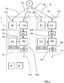
Figure 4 ,Figure 5 and Figure 6 , thefirst transmitter arrangement 8a further comprises aphase switch 15a connected between thesignal generator 9a and the second transmitter antenna device 10a2. The phase switch 15 is arranged to switch between 0° phase shift, as illustrated inFigure 5 and Figure 7 , and 180° phase shift, as illustrated inFigure 6 and Figure 8 . -
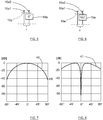
Figure 7 shows a first relativeantenna radiation pattern 40 with magnitude in dB on the y-axis and azimuth angle on the x-axis.Figure 8 shows a second relativeantenna radiation pattern 41 with magnitude in dB on the y-axis and azimuth angle on the x-axis. The relativeantenna radiation patterns - With the
phase switch 15a in the 0° setting as illustrated inFigure 5 , the radiated energy is focused towards boresight, at 0° in the first relativeantenna radiation pattern 40 inFigure 7 , which constitutes asum pattern 40. With thephase switch 15a in the 180° setting as illustrated inFigure 6 , the radiated energy has a deep notch in boresight, at 0° in the second relative antenna radiation pattern diagram 41 inFigure 8 , which constitutes adelta pattern 41. - In the latter case, the pole at 0° in the
delta pattern 41 is important to distinguish object position from being on the left or right side of the firstradar sensor arrangement 4a. - The
sum pattern 40 is thus obtained by feeding both transmitter antenna devices 10a1, 10a2 in phase, while thedelta pattern 41 is obtained feeding both transmitter antenna devices 10a1, 10a2 out of phase with each other, here with a mutual 180° phase difference. - It is desirable that side lobes, including grating lobes, are suppressed as much as possible.
- When a
target object 5 has been detected, its delta azimuth angle in thedelta pattern 41 will be estimated. Furthermore, it is supposed that the complex amplitude of thetarget object 5 is available for both thesum pattern 40 and thedelta pattern 41. - A bearing calculation will be based on the theory of an amplitude-sensing monopulse (ASM). The name derives from the fact that the method is theoretically capable of obtaining a target object's angles using only one (mono) pulse. It uses the amplitude characteristic (magnitude) of its antenna pattern to determine an angular position of a detected target object. Due to the
sum pattern 40 and thedelta pattern 41 being mirror-symmetric to its corresponding boresight, the phase conditions are used to obtain the sign of the azimuth angle of thetarget object 5. - An additive sensing ratio (ASR) is defined as:

- Here, MΣ corresponds to the magnitude of the
sum pattern 40, and MΔ corresponds to the magnitude of thedelta pattern 41. With reference toFigure 5 , theASR 42 is schematically indicated as a function of azimuth angle. Note that the symmetric antenna characteristics imply that the corresponding ASR function does not behave strictly monotonic. Consequently, a unique angle cannot be assigned to a particular ASR phase. The phase characteristics of the relativeantenna radiation patterns - With reference to
Figure 10 , showing the firstreceiver antenna arrangement 13a that comprises the first receiver antenna device 13a1, the second receiver antenna device 13a2, the third receiver antenna device 13a3 and the fourth receiver antenna device 13a4, there is a certain spacing k·λ between adjacent receiver antenna devices 13a1, 13a2, 13a3, 13a4. λ is a wavelength corresponding to a center frequency of a desired frequency band, and k is a constant that is chosen for desired functionality. - Said spacing k·λ has an important significance for the antenna design. On the one hand, a high degree of angular resolution and accuracy is desired, which requires a large antenna distance. On the other hand, a high degree of unambiguous range is also desire, which requires a relatively small antenna spacing. In some cases, both resolution and accuracy may be reduced in favor of a reasonable unambiguous range.
- In practice, additional restrictions arise from a relatively small antenna aperture. First to mention would be an undesired crosstalk between the receiver antenna devices 13a1, 13a2, 13a3, 13a4. The intensity of this crosstalk follows inherently a function of the antenna separation. This behavior may create unpredictable nonlinearities in the bearing processing. Another disadvantage of a relatively small antenna aperture is limited antenna gain, and consequently the SNR of the received signal.
- Another aspect of the antenna design is the influence of the vehicle environment, such as for example bumper integration or a further radome with or without heating, on the radar performance. A variety of factors should therefore be considered; for example uncontrolled wave propagation, unintentional mode creation, etc. All of these effects also have negative impact on the processing. However, a relatively large antenna spacing mitigate some harmful external effects.
- According to some aspects, the constant k is chosen to be about 1.5 - 2.0.
- With reference to
Figure 5 and Figure 6 , for the adjacent transmitter antenna device 10a1, 10a2 there is a spacing r that according to some aspects has a magnitude of about 0.5·λ. - Exactly how data processing is accomplished in practice may vary, the example disclosed above is only an example, and the processing may be performed in any suitable processing unit.
- Each
control unit 25a, 25b; 38 may be comprised by one or more separate or integrated control units, e.g. SoCs (System-on-Chips). - As indicated in
Figure 1 , thevehicle 1 comprises asafety control unit 54 and safety means 55, for example an emergency braking system and/or an alarm signal device. Thesafety control unit 54 is arranged to control the safety means 55 in dependence of input from theradar system 3. Such input may be input via themain control unit 38. - With reference to
Figure 11 , the present disclosure also relates to a method for avehicle radar system 3, where the method comprises: - 48: Generating at least two receiver
antenna radiation beams maximum gain extension maximum gain extension - 49: Generating and transmitting
radar signals - 50: Receiving reflected
signals chirp signals object 5. - 51: Transmitting the
radar signals - 52: Obtaining information regarding the time for transmission of each plurality of
radar signals radar sensor arrangement - The present disclosure is not limited to the examples above, but may vary freely within the scope of the appended claims. For example, the ramp time Tr does not have to be the same for the
first chirp signal 4a and thesecond chirp signal 4b. - Each ramp may be configured as an up-ramp as described, or a down-ramp, or some combination of both such as saw-tooth. The magnitude of the first frequency fstart may thus exceed the magnitude of the second frequency fstop.
- Other kinds of FMCW signals and FMCW signal configurations are also conceivable, as well as other types of Doppler radar signals. Other types of radar systems are also conceivable; not only FMCW radar systems are conceivable. Pulse radar, FSK (frequency-shift keying) or CW (continuous wave) waveform are also conceivable like all other kinds of suitable modulation techniques.
- Furthermore, there may be any number of transmitter antenna devices 10a1, 10a2 and receiver antenna devices 13a1, 13a2, 13a3, 13a4, but there is at least two transmitter antenna devices for each
transmitter antenna arrangement receiver antenna arrangement - Each antenna device 10a1, 10a2; 13a1, 13a2, 13a3, 13a4 may for example be constituted by one antenna element or by an array of antenna elements.
- The radar system may be implemented in any type of vehicle such as cars, trucks and buses as well as boats and aircraft.
- The schematics of vehicle radar systems are simplified, only showing parts that are considered relevant for an adequate description of the present disclosure. It is understood that the general design of radar systems of this kind is well-known in the art.
- Furthermore, no devices that are arranged to use the acquired target information are shown, but many different such devices are of course conceivable; for example a warning and/or collision avoidance system.
- The ADC arrangement and the DSP arrangement should each one be interpreted as having a corresponding ADC or DSP functionality, and may each be constituted by a plurality of separate components. Alternatively, each ADC arrangement may be comprised in one ADC chip, and each DSP arrangement may be comprised in one DSP chip.
- Generally, the hardware used to generate the radar signal may be arranged to be powered down when it is not needed.
- Beamforming may be used, for example in the form of digital beamforming (DBF) but other types of beamforming are conceivable. According to an aspect, an ASM transmitter is combined with an analog beamforming receiver. In this case the steering would be achieved with phase-shifter components in between the antenna elements. This technique is also known as 'Phased Array Radar'.
- When a phase shift of 180° is mentioned, the mathematically exact figure is not intended, but a phase shift within what is practically obtainable that provides a
sum pattern 40 and adelta pattern 41. Therefore, in practice, for delta pattern signals,radar signals radar signals - According to some aspects, only one type of
radar sensor arrangement - Azimuth multipath can be used for increasing the ability to determine distances between different parts of an object in front of the
vehicle 1, since transmitted signals from theradar sensor arrangements radar sensor arrangement - Wordings such as simultaneous are not intended to be understood as mathematically exact, but within what is practically obtainable.
- In this context, a radar cycle is according to some aspects one observation phase during which the vehicle radar system (3) is arranged to acquire data, process said data on several signal processing levels and to send out available results. This can be a fixed time interval or a dynamic time interval depending on environment conditions and processing load.
- The radar sensor arrangements (4a, 4b) are arranged to transmit any suitable radar signals, which can be TDM (Time division multiplexed) radar signals. FMCW is a kind of TDM radar signals.
- Generally, the present disclosure relates to a
vehicle radar system 3 comprising amain control unit 38, a firstradar sensor arrangement 4a and a secondradar sensor arrangement 4b, whichradar sensor arrangements vehicle 1 arranged to run along a forward direction F, where theradar sensor arrangements transmitter antenna arrangement receiver antenna arrangement receiver antenna arrangement antenna radiation beam maximum gain extension maximum gain extension radar sensor arrangement radar signals reflected signals radar signals object 5. Theradar sensor arrangements radar signals main control unit 38 is arranged to obtain information regarding the time for transmission of each plurality ofradar signals radar sensor arrangement - According to some aspects, the beam pointing azimuth angles ϕ1, ϕ2 have a respective value between 0° and 1.5°.
- According to some aspects, each
radar sensor arrangement chirp signals - According to some aspects, the
main control unit 38 is arranged to insert at least one identifiable data signal 40a, 40b; 41a, 41b for each radar cycle. - According to some aspects, each
identifiable data signal - According to some aspects, each
identifiable data signal - According to some aspects, the time indication includes time-stamping on data frames of raw data of the MMIC Monolithic Microwave Integrated Circuits.
- According to some aspects, the
main control unit 38 is arranged to control the coherency of the received reflectedsignals identifiable data signals - According to some aspects, the
vehicle radar system 3 comprises amain clock 26 that is arranged as a system clock for themain control unit 38, and that eachradar sensor arrangement local clock 24a, 24b and a correspondinglocal control unit 25a, 25b. - According to some aspects, the
main control unit 38 is arranged to acquire time data from themain clock 26 and to synchronize thelocal clocks 24a, 24b. - According to some aspects, the
main control unit 38 is arranged to control a phase difference between the receivedradar signals radar signals - According to some aspects, the
main control unit 38 is arranged to combine the two receiverantenna radiation beams overlap area 28 is provided, where theoverlap area 28 enables overlap processing. - According to some aspects, the transmitter antenna devices 10a1, 10a2 are arranged to transmit by means of a first relative
antenna radiation pattern 40 and by means of a second relative antenna radiation pattern diagram 41, where the first relativeantenna radiation pattern 40 is obtained by feeding two transmitter antenna devices 10a1, 10a2 in phase, while the second relative antenna radiation pattern diagram 41 is obtained by feeding two transmitter antenna devices 10a1, 10a2 out of phase with each other. - Generally, the present disclosure also relates to a method for a
vehicle radar system 3, where the method comprises: - 48: generating at least two receiver
antenna radiation beams maximum gain extension maximum gain extension - 49: generating and transmitting
radar signals - 50: receiving reflected
signals radar signals object 5. - The method further comprises:
- 51: transmitting the
radar signals - 52: obtaining information regarding the time for transmission of each plurality of
radar signals radar sensor arrangement - According to some aspects, the beam pointing azimuth angles ϕ1, ϕ2 have a respective value between 0° and 1.5°.
Claims (15)
- A vehicle radar system (3) comprising a main control unit (38), a first radar sensor arrangement (4a) and a second radar sensor arrangement (4b), which radar sensor arrangements (4a, 4b) are arranged to be mounted at the front of a vehicle (1) arranged to run along a forward direction (F), where the radar sensor arrangements (4a, 4b) are separated by a certain distance (d) and comprise a corresponding transmitter antenna arrangement (10a, 10b) and corresponding receiver antenna arrangement (13a, 13b), where each receiver antenna arrangement (13a, 13b) has a corresponding receiver antenna radiation beam (47a, 47b) with a corresponding beam pointing azimuth angle (ϕ1, ϕ2) relative the forward direction (F) in a corresponding maximum gain extension (46a, 46b), where the maximum gain extension (46a, 46b) converge for beam pointing azimuth angles (ϕ1, ϕ2) exceeding 0°, where each radar sensor arrangement (4a, 4b) is arranged for generating and transmitting radar signals (6a, 6b) in radar cycles, and to receive reflected signals (7a, 7b), where the transmitted radar signals (6a, 6b) have been reflected by an object (5), characterized in that the radar sensor arrangements (4a, 4b) are arranged to transmit the radar signals (6a, 6b) during a common time period for a major part of each radar cycle, where the main control unit (38) is arranged to obtain information regarding the time for transmission of each plurality of radar signals (6a, 6b) for each radar sensor arrangement (4a, 4b).
- The vehicle radar system (3) according to claim 1, characterized in that the beam pointing azimuth angles (ϕ1, ϕ2) have a respective value between 0° and 1.5°.
- The vehicle radar system (3) according to any one of the claims 1 or 2, characterized in that each radar sensor arrangement (4a, 4b) is arranged for generating and transmitting FMCW, Frequency Modulated Continuous Wave, chirp signals, where each radar cycle comprises a plurality of chirp signals (6a, 6b).
- The vehicle radar system (3) according to any one of the previous claims, characterized in that the main control unit (38) is arranged to insert at least one identifiable data signal (40a, 40b; 41a, 41b) for each radar cycle.
- The vehicle radar system (3) according to claim 4, characterized in that each identifiable data signal (40a, 40b) comprises a synchronization.
- The vehicle radar system (3) according to any one of the claims 4 or 5, characterized in that each identifiable data signal (41a, 41b) comprises a time indication.
- The vehicle radar system (3) according to claim 6, characterized in that the time indication includes time-stamping on data frames of raw data of the MMIC (Monolithic Microwave Integrated Circuits).
- The vehicle radar system (3) according to any one of the claims 4-7, characterized in that the main control unit (38) is arranged to control the coherency of the received reflected signals (7a, 7b) by means of said identifiable data signals (40a, 40b; 41a, 41b).
- The vehicle radar system (3) according to any one of the previous claims, characterized in that the vehicle radar system (3) comprises a main clock (26) that is arranged as a system clock for the main control unit (38), and that each radar sensor arrangement (4a, 4b) comprises a corresponding local clock (24a, 24b) and a corresponding local control unit (25a, 25b) .
- The vehicle radar system (3) according to claim 9, characterized in that the main control unit (38) is arranged to acquire time data from the main clock (26) and to synchronize the local clocks (24a, 24b).
- The vehicle radar system (3) according to any one of the previous claims, characterized in that the main control unit (38) is arranged to control a phase difference between the received radar signals (7a, 7b) for synchronization to enable coherency control of the received radar signals (7a, 7b) in time domain or frequency domain.
- The vehicle radar system (3) according any one of the previous claims, characterized in that the main control unit (38) is arranged to combine the two receiver antenna radiation beams (47a, 47b) such that an overlap area (28) is provided, where the overlap area (28) enables overlap processing.
- The vehicle radar system (3) according to any one of the previous claims, characterized in that the transmitter antenna devices (10a1, 10a2) are arranged to transmit by means of a first relative antenna radiation pattern (40) and by means of a second relative antenna radiation pattern diagram (41), where the first relative antenna radiation pattern (40) is obtained by feeding two transmitter antenna devices (10a1, 10a2) in phase, while the second relative antenna radiation pattern diagram (41) is obtained by feeding two transmitter antenna devices (10a1, 10a2) out of phase with each other.
- A method for a vehicle radar system (3), where the method comprises:(48) generating at least two receiver antenna radiation beams (47a, 47b) with a corresponding beam pointing azimuth angle (ϕ1, ϕ2) relative a forward direction (F) in a corresponding maximum gain extension (46a, 46b), where the maximum gain extension (46a, 46b) converge for beam pointing azimuth angles (ϕ1, ϕ2) exceeding 0°;(49) generating and transmitting radar signals (6a, 6b) in radar cycles; and(50) receiving reflected signals (7a, 7b), where the transmitted radar signals (6a, 6b) have been reflected by an object (5), characterized in that the method comprises:(51) transmitting the radar signals (6a, 6b) during a common time period for a major part of each radar cycle; and(52) obtaining information regarding the time for transmission of each plurality of radar signals (6a, 6b) for each radar sensor arrangement (4a, 4b).
- The method according to claim 14, characterized in that the beam pointing azimuth angles (ϕ1, ϕ2) have a respective value between 0° and 1.5°.
Priority Applications (1)
| Application Number | Priority Date | Filing Date | Title |
|---|---|---|---|
| EP17176781.7A EP3418768A1 (en) | 2017-06-20 | 2017-06-20 | A vehicle radar system comprising two radar sensor arrangements |
Applications Claiming Priority (1)
| Application Number | Priority Date | Filing Date | Title |
|---|---|---|---|
| EP17176781.7A EP3418768A1 (en) | 2017-06-20 | 2017-06-20 | A vehicle radar system comprising two radar sensor arrangements |
Publications (1)
| Publication Number | Publication Date |
|---|---|
| EP3418768A1 true EP3418768A1 (en) | 2018-12-26 |
Family
ID=59091416
Family Applications (1)
| Application Number | Title | Priority Date | Filing Date |
|---|---|---|---|
| EP17176781.7A Pending EP3418768A1 (en) | 2017-06-20 | 2017-06-20 | A vehicle radar system comprising two radar sensor arrangements |
Country Status (1)
| Country | Link |
|---|---|
| EP (1) | EP3418768A1 (en) |
Cited By (5)
| Publication number | Priority date | Publication date | Assignee | Title |
|---|---|---|---|---|
| CN111080818A (en) * | 2019-12-10 | 2020-04-28 | 北京聚利科技有限公司 | Charging method and system |
| DE102019130373A1 (en) * | 2019-11-11 | 2021-05-12 | Valeo Schalter Und Sensoren Gmbh | Environment monitoring of a motor vehicle |
| EP3885785A1 (en) * | 2020-03-26 | 2021-09-29 | INTEL Corporation | Apparatus, system and method of communicating radar signals |
| CN113567987A (en) * | 2021-04-30 | 2021-10-29 | 华为技术有限公司 | Radar system and terminal equipment |
| US11686841B2 (en) | 2021-04-30 | 2023-06-27 | Huawei Technologies Co., Ltd. | Radar system and terminal device |
Citations (4)
| Publication number | Priority date | Publication date | Assignee | Title |
|---|---|---|---|---|
| DE102005056800A1 (en) * | 2005-11-29 | 2007-05-31 | Valeo Schalter Und Sensoren Gmbh | Motor vehicle radar system operating method, involves receiving transmission signal by sensor module in monitoring mode to obtain information about operating condition of another module, where signal is transmitted from latter module |
| EP2333578A2 (en) * | 2009-12-02 | 2011-06-15 | Robert Bosch GmbH | Method and control device for determining a movement direction of an object moving towards a vehicle |
| EP2629115A1 (en) * | 2012-02-17 | 2013-08-21 | Hella KGaA Hueck & Co. | Sensor device |
| EP3056920A1 (en) * | 2015-02-11 | 2016-08-17 | Autoliv Development AB | A vehicle radar system with two transceiver arrangements |
-
2017
- 2017-06-20 EP EP17176781.7A patent/EP3418768A1/en active Pending
Patent Citations (4)
| Publication number | Priority date | Publication date | Assignee | Title |
|---|---|---|---|---|
| DE102005056800A1 (en) * | 2005-11-29 | 2007-05-31 | Valeo Schalter Und Sensoren Gmbh | Motor vehicle radar system operating method, involves receiving transmission signal by sensor module in monitoring mode to obtain information about operating condition of another module, where signal is transmitted from latter module |
| EP2333578A2 (en) * | 2009-12-02 | 2011-06-15 | Robert Bosch GmbH | Method and control device for determining a movement direction of an object moving towards a vehicle |
| EP2629115A1 (en) * | 2012-02-17 | 2013-08-21 | Hella KGaA Hueck & Co. | Sensor device |
| EP3056920A1 (en) * | 2015-02-11 | 2016-08-17 | Autoliv Development AB | A vehicle radar system with two transceiver arrangements |
Cited By (8)
| Publication number | Priority date | Publication date | Assignee | Title |
|---|---|---|---|---|
| DE102019130373A1 (en) * | 2019-11-11 | 2021-05-12 | Valeo Schalter Und Sensoren Gmbh | Environment monitoring of a motor vehicle |
| WO2021094234A1 (en) | 2019-11-11 | 2021-05-20 | Valeo Schalter Und Sensoren Gmbh | Monitoring the surroundings of a motor vehicle |
| CN111080818A (en) * | 2019-12-10 | 2020-04-28 | 北京聚利科技有限公司 | Charging method and system |
| EP3885785A1 (en) * | 2020-03-26 | 2021-09-29 | INTEL Corporation | Apparatus, system and method of communicating radar signals |
| US11448722B2 (en) | 2020-03-26 | 2022-09-20 | Intel Corporation | Apparatus, system and method of communicating radar signals |
| US11762057B2 (en) | 2020-03-26 | 2023-09-19 | Intel Corporation | Apparatus, system and method of communicating radar signals |
| CN113567987A (en) * | 2021-04-30 | 2021-10-29 | 华为技术有限公司 | Radar system and terminal equipment |
| US11686841B2 (en) | 2021-04-30 | 2023-06-27 | Huawei Technologies Co., Ltd. | Radar system and terminal device |
Similar Documents
| Publication | Publication Date | Title |
|---|---|---|
| US11762084B2 (en) | Vehicle radar system | |
| EP3418768A1 (en) | A vehicle radar system comprising two radar sensor arrangements | |
| EP3147685B1 (en) | A vehicle synthetic aperture radar system | |
| JP2024042029A (en) | Method and device for capturing surroundings | |
| US8717224B2 (en) | Integrated radar apparatus and intergrated antenna apparatus | |
| US9470782B2 (en) | Method and apparatus for increasing angular resolution in an automotive radar system | |
| US11422249B2 (en) | Radar device and method for detecting radar targets | |
| KR20180083865A (en) | Radar systems including interleaved serial transmission and parallel reception | |
| US20120242530A1 (en) | Method for unambiguously determining a range and/or a relative speed of an object, driver assistance device and motor vehicle | |
| CN111157981A (en) | Multiple-input multiple-output frequency modulation continuous wave radar system | |
| JPH04220582A (en) | Poly-static correlation radar | |
| US20180284267A1 (en) | A modular vehicle radar | |
| WO2018002233A1 (en) | A vehicle radar for environmental detection | |
| KR20200124838A (en) | Radar Apparatus and Objection Detection Method, and Signal Processing Apparatus therefor | |
| EP2096457B1 (en) | Digital beam forming using frequency-modulated signals | |
| JP2016151424A (en) | Radar system | |
| US10816660B2 (en) | Close range filtering vehicle radar | |
| Ramasubramanian | mmWave radar for automotive and industrial applications | |
| Burov et al. | Development of the automotive radar for the systems of adaptive cruise control and automatic emergency breaking | |
| US11802960B2 (en) | Phase correcting apparatus and method of transmission signal of vehicle radar, and vehicle radar apparatus with the same | |
| IL278587A (en) | Efficient direction of arrival estimation using low rank approximation | |
| EP3176604B1 (en) | A monopulse vehicle radar system | |
| US20230003518A1 (en) | Vehicle radar apparatus and method of controlling the same | |
| RU2761928C1 (en) | Radar sensor for vehicle collision prevention | |
| Ogawa et al. | Development of Automotive Millimeter Wave Radars |
Legal Events
| Date | Code | Title | Description |
|---|---|---|---|
| PUAI | Public reference made under article 153(3) epc to a published international application that has entered the european phase |
Free format text: ORIGINAL CODE: 0009012 |
|
| STAA | Information on the status of an ep patent application or granted ep patent |
Free format text: STATUS: THE APPLICATION HAS BEEN PUBLISHED |
|
| AK | Designated contracting states |
Kind code of ref document: A1 Designated state(s): AL AT BE BG CH CY CZ DE DK EE ES FI FR GB GR HR HU IE IS IT LI LT LU LV MC MK MT NL NO PL PT RO RS SE SI SK SM TR |
|
| AX | Request for extension of the european patent |
Extension state: BA ME |
|
| STAA | Information on the status of an ep patent application or granted ep patent |
Free format text: STATUS: REQUEST FOR EXAMINATION WAS MADE |
|
| 17P | Request for examination filed |
Effective date: 20190625 |
|
| RBV | Designated contracting states (corrected) |
Designated state(s): AL AT BE BG CH CY CZ DE DK EE ES FI FR GB GR HR HU IE IS IT LI LT LU LV MC MK MT NL NO PL PT RO RS SE SI SK SM TR |
|
| STAA | Information on the status of an ep patent application or granted ep patent |
Free format text: STATUS: EXAMINATION IS IN PROGRESS |
|
| 17Q | First examination report despatched |
Effective date: 20210528 |
|
| STAA | Information on the status of an ep patent application or granted ep patent |
Free format text: STATUS: EXAMINATION IS IN PROGRESS |
|
| RAP1 | Party data changed (applicant data changed or rights of an application transferred) |
Owner name: ARRIVER SOFTWARE AB |