EP3138739A1 - Side airbag apparatus for vehicle - Google Patents
Side airbag apparatus for vehicle Download PDFInfo
- Publication number
- EP3138739A1 EP3138739A1 EP15785452.2A EP15785452A EP3138739A1 EP 3138739 A1 EP3138739 A1 EP 3138739A1 EP 15785452 A EP15785452 A EP 15785452A EP 3138739 A1 EP3138739 A1 EP 3138739A1
- Authority
- EP
- European Patent Office
- Prior art keywords
- vehicle
- side airbag
- folded
- inflator
- superposed
- Prior art date
- Legal status (The legal status is an assumption and is not a legal conclusion. Google has not performed a legal analysis and makes no representation as to the accuracy of the status listed.)
- Granted
Links
Images


Classifications
-
- B—PERFORMING OPERATIONS; TRANSPORTING
- B60—VEHICLES IN GENERAL
- B60R—VEHICLES, VEHICLE FITTINGS, OR VEHICLE PARTS, NOT OTHERWISE PROVIDED FOR
- B60R21/00—Arrangements or fittings on vehicles for protecting or preventing injuries to occupants or pedestrians in case of accidents or other traffic risks
- B60R21/02—Occupant safety arrangements or fittings, e.g. crash pads
- B60R21/16—Inflatable occupant restraints or confinements designed to inflate upon impact or impending impact, e.g. air bags
- B60R21/23—Inflatable members
- B60R21/237—Inflatable members characterised by the way they are folded
-
- B—PERFORMING OPERATIONS; TRANSPORTING
- B60—VEHICLES IN GENERAL
- B60N—SEATS SPECIALLY ADAPTED FOR VEHICLES; VEHICLE PASSENGER ACCOMMODATION NOT OTHERWISE PROVIDED FOR
- B60N2/00—Seats specially adapted for vehicles; Arrangement or mounting of seats in vehicles
- B60N2/24—Seats specially adapted for vehicles; Arrangement or mounting of seats in vehicles for particular purposes or particular vehicles
- B60N2/42—Seats specially adapted for vehicles; Arrangement or mounting of seats in vehicles for particular purposes or particular vehicles the seat constructed to protect the occupant from the effect of abnormal g-forces, e.g. crash or safety seats
-
- B—PERFORMING OPERATIONS; TRANSPORTING
- B60—VEHICLES IN GENERAL
- B60R—VEHICLES, VEHICLE FITTINGS, OR VEHICLE PARTS, NOT OTHERWISE PROVIDED FOR
- B60R21/00—Arrangements or fittings on vehicles for protecting or preventing injuries to occupants or pedestrians in case of accidents or other traffic risks
- B60R21/02—Occupant safety arrangements or fittings, e.g. crash pads
- B60R21/16—Inflatable occupant restraints or confinements designed to inflate upon impact or impending impact, e.g. air bags
- B60R21/20—Arrangements for storing inflatable members in their non-use or deflated condition; Arrangement or mounting of air bag modules or components
- B60R21/207—Arrangements for storing inflatable members in their non-use or deflated condition; Arrangement or mounting of air bag modules or components in vehicle seats
-
- B—PERFORMING OPERATIONS; TRANSPORTING
- B60—VEHICLES IN GENERAL
- B60R—VEHICLES, VEHICLE FITTINGS, OR VEHICLE PARTS, NOT OTHERWISE PROVIDED FOR
- B60R21/00—Arrangements or fittings on vehicles for protecting or preventing injuries to occupants or pedestrians in case of accidents or other traffic risks
- B60R21/02—Occupant safety arrangements or fittings, e.g. crash pads
- B60R21/16—Inflatable occupant restraints or confinements designed to inflate upon impact or impending impact, e.g. air bags
- B60R21/23—Inflatable members
- B60R21/231—Inflatable members characterised by their shape, construction or spatial configuration
- B60R21/23138—Inflatable members characterised by their shape, construction or spatial configuration specially adapted for side protection
- B60R2021/23146—Inflatable members characterised by their shape, construction or spatial configuration specially adapted for side protection seat mounted
Definitions
- the present invention relates to a vehicle side airbag device capable of reducing/alleviating the movement of a deployed and inflated side airbag to jerk up the arm of an occupant and improving the occupant restraining performance.
- PTL 1 to 3 disclose prior-art techniques related to vehicle side airbag devices, which include taking up a side airbag obliquely with respect to the vertical direction and spreading the side airbag upward in the process of deployment and inflation.
- the "airbag device for side collision” disclosed in PTL 1 is aimed to deploy an airbag quickly after detection of a side collision, and the airbag is folded into a long band shape in the deployment direction and in a spirally rolled state while its surface, which is to face the vehicle interior side wall during deployment, is positioned outside, and the airbag is adapted to be deployed forward as its outer side surface is abutted against the vehicle interior side wall and the rolled state is unfolded upon a side collision.
- the "structure and method for folding an airbag” in PTL 2 is directed to the object of providing a structure and method for folding an airbag that allows improved deployment speed and smooth deployment behavior to be obtained, and here, a head protection portion is rolled a number of times while its protection surface faces inside, the head protection portion is pushed into a chest protection portion, and at this time, part of the chest protection portion coupled to the head protection portion is pushed into the chest protection portion.
- the "airbag device for side collision” disclosed in PTL 3 is aimed to provide an airbag device for side collision capable of providing a folded airbag near an upper end of the backrest of a seat without preventing smooth inflation of the airbag, and the airbag device for side collision has the folded airbag on the upper side of the backrest of the seat.
- the airbag is attached and fixed to the seat frame in a plurality of locations in the vertical direction on the rear edge side and has a lower chamber upstream of inflation gas and an upper chamber provided above the front side of the lower chamber, and the airbag is stored in a folded state and adapted to project forward and deployed upward during inflation.
- the airbag is provided with radial folding lines around the upper part side of the lower chamber on the rear edge side, and the upper chamber and the lower chamber are folded in a sector shape and stored on the rear edge side of the lower chamber.
- a side airbag is a countermeasure against a side collision and deployed and inflated toward the vehicle front side between an occupant and a vehicle component, such as a door, that is positioned laterally to the occupant in the vehicle-widthwise direction.
- the side airbag is intended to spread swiftly and smoothly upward.
- the side airbag may enter below the arm of the occupant or the arm of the occupant may be unintendedly positioned above the side airbag and directly jerked up by the side airbag in a violent, instantaneous manner, which can place an unwanted load upon the occupant and may bring the occupant into an unbalanced position, such that appropriate occupant restraining performance could not be provided.
- the present invention is devised in view of the above-described problem associated with the prior art, and it is an object of the present invention to provide a vehicle side airbag device capable of reducing/alleviating the movement of a deployed and inflated airbag to jerk up the arm of an occupant and improving the occupant restraining performance.
- a vehicle side airbag device includes a side airbag provided inside a vehicle seat and allowed to be deployed and inflated from the seat into between an occupant and a vehicle component positioned laterally to the occupant in a vehicle-widthwise direction and an inflator attachable to a seat frame of the seat and causing inflator gas to be introduced into the side airbag, the inflator is stored inside the side airbag near a rear end thereof in a deployment and inflation direction, in a spread state, the side airbag has a folded portion with a folding line and a superposed portion in series sequentially from a side of the inflator to a front end thereof in the deployment and inflation direction, in a stored state before deployment, the folded portion is formed to include an abutment portion folded back to a vehicle rear side from a vehicle front side and abutted against the seat frame during attachment to the seat on a front side of the inflator in a vehicle front-back direction, the superposed portion is formed to be superposed in a rolled state or folded
- the folded portion is preferably configured to be capable of pushing out the superposed portion toward the vehicle component in the vehicle-widthwise direction upon receiving reaction force from the seat frame during deployment and inflation of the side airbag.
- the vehicle component is desirably a vehicle door or a console box provided on a center side in the vehicle in the vehicle-widthwise direction.
- the side airbag is preferably folded to have an upper part in the up-down direction placed on a lower part before the folded portion and the superposed portion are formed.
- the side airbag has an additional folded portion with an additional folding line between the folded portion and the superposed portion; in a stored state before deployment, the additional folded portion is formed to be folded back at least once along the additional folding line to the vehicle rear side from the vehicle front side or conversely in an arrangement parallel to the folded portion; and the superposed portion is arranged between the additional folded portion and the folded portion in the vehicle-widthwise direction.
- the movement of a deployed and inflated side airbag to jerk up the arm of an occupant can be reduced/alleviated and the occupant restraining performance can be improved.
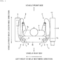
- Fig. 1 is a plan view of a side airbag in a vehicle side airbag device according to the embodiment in a deployed and inflated state as viewed from above
- Fig. 2 is a view for illustrating a first stage of the assembling procedure of assembling the side airbag shown in Fig. 1 into a stored state
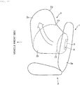
- Fig. 3 is a view for illustrating a second stage of the assembling procedure
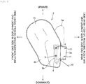
- Fig. 4 is a view for illustrating a third stage of the assembling procedure
- Fig. 5 is a view for illustrating a fourth stage of the assembling procedure
- Fig. 1 is a plan view of a side airbag in a vehicle side airbag device according to the embodiment in a deployed and inflated state as viewed from above
- Fig. 2 is a view for illustrating a first stage of the assembling procedure of assembling the side airbag shown in Fig. 1 into a stored state
- Fig. 3 is a view for illustrating a second stage of the assembling procedure
- FIG. 6 is a view for illustrating a fifth stage of the assembling procedure
- Fig. 7 is a schematic view for illustrating the first half of the assembling procedure described above
- Fig. 8 is a schematic view for illustrating the second half of the assembling procedure described above
- Fig. 9 is a plan view of the side airbag (rolled type) shown in Fig. 1 in a stored state before deployment showing from above how the side airbag is attached to a seat frame
- Fig. 10 is a plan view of the side airbag (bellows-like type) shown in Fig. 1 in a stored state before deployment showing from above how the side airbag is attached to the seat frame
- Fig. 11 is a view for illustrating how the side airbag shown in Fig. 1 is inflated and deployed as viewed from above
- Fig. 12 is a view for illustrating the side airbag shown in Fig. 11 in the process of the deployment and inflation as viewed from the side.
- a side airbag 2 in a vehicle side airbag device 1 is provided inside a seat back 3a of a seat 3 provided in a vehicle as the airbag is stored in a rolled up or collapsed state before deployment and inflation.
- An occupant P is seated at the seat 3.
- vehicle components such as a door 4 (on the vehicle exterior side) and a console box 5 (on the vehicle interior side) on the center side in the vehicle-widthwise direction are provided in lateral positions to the occupant P in the vehicle-widthwise direction, in other words, in positions facing the sides of the occupant P.
- the side airbag 2 in response to an impact upon the vehicle caused by a side collision for example, the side airbag 2 is deployable and inflatable from the seat back 3a to the front side of the seat 3, in other words, forward in the front-back lengthwise direction of the vehicle (hereinafter as the vehicle front-back direction), into between the occupant P and the vehicle component such as the door 4 and the console box 5 positioned laterally to the occupant P in the vehicle-widthwise direction. Therefore, as shown in Fig. 2 , the part of the side airbag 2 on the side of the seat back 3a (the vehicle rear side) corresponds to the rear end side in the deployment and inflation direction, and the vehicle front side corresponds to the front end side in the deployment and inflation direction.
- the deployment and inflation of the side airbag 2 from its stored state is achieved by introduction of inflator gas from an inflator 6 into the side airbag 2.
- the side airbag 2 is normally deployed and inflated in a range from the hips of the occupant P to above the head, restrains the occupant P toward the seat 3, blocks the vehicle component such as the door 4 from the occupant P to protect the occupant P, and reduces the injury value for the occupant P.
- a firm seat frame 7 for receiving and supporting the body of the occupant P or the like resting thereupon is provided in the seat back 3a.
- the seat frame 7 is a frame including a channel member or a square tube.
- the seat frame 7 has a plane portion facing the side of the vehicle component such as the door 4, and according to the embodiment, the plane portion forms a support surface 7a used to attach the inflator 6 or support the side airbag 2 to be deployed and inflated. Therefore, the inflator 6 can be attached to the seat 3, for example at the seat frame 7.
- Stud bolts 8 are provided integrally on one side of the inflator 6 and fixed by nuts 9 to the support surface 7a of the seat frame 7 inside the seat back 3a.
- the inflator 6 is attached to the support surface 7a of the seat frame 7 as the stud bolts 8 are fixed to the seat frame 7.
- the inflator 6 is stored in the side airbag 2. The storing position of the inflator 6 is set near the rear end of the side airbag 2 in the deployment and inflation direction.
- the inflator 6 stored in the side airbag 2 is attached to the seat frame 7, so that the part of the side airbag 2 near the rear end in the deployment and inflation direction is fixed to the seat frame 7. Since the inflator 6 is stored in the side airbag 2, inflator gas ejected from the inflator 6 fills up the side airbag 2 to deploy and inflate the side airbag 2.
- Fig. 2 shows the side airbag 2 in a flat spread out state.
- the upward direction corresponds to the upward direction in the vehicle up-down height-wise direction (hereinafter referred to as the height-wise direction)
- the downward direction corresponds to the downward direction in the height-wise direction
- the leftward corresponds to the front end side in the deployment and inflation direction (the vehicle front side)
- the rightward corresponds to the rear end side in the deployment and inflation direction (the vehicle rear side).
- the side airbag 2 is formed into a bag shape having an opening portion 2a by placing two sheets of ground fabric on each other or folding a sheet of ground fabric and placing the folds upon each other and then stitching the peripheries together to join them.
- the opening portion 2a is formed to protrude to the vehicle rear side toward the rear end in the deployment and inflation direction (hereinafter referred to as the rear end in the deployment direction).
- the inflator 6 is stored inside the side airbag 2 through the opening portion 2a.
- the stud bolts 8 protrude outwardly from the side airbag 2 through bolt holes formed at the side airbag 2.
- 10 designates a harness.
- the external shape of the side airbag 2 has a larger size in the vehicle up-down direction than its length in the vehicle front-back direction.
- the side airbag 2 is generally directed obliquely upward from the storing position of the inflator 6 to the front side in the vehicle front-back direction.
- the upper part 2c is formed to be directed obliquely upward to the front side in the vehicle front-back direction.
- the region from the hips to the head of the occupant P that can move forward in the vehicle and outward in the vehicle-widthwise direction upon a side collision or the like can be received and restrained by the entire side airbag 2 and protected.
- the opening portion 2a of the side airbag 2 is folded back to the front end in the deployment and inflation direction (hereinafter referred to as the front end in the deployment direction) and is partly placed on the lower part 2b of the side airbag 2 so that the opening portion overlaps the storing position of the inflator 6.
- the opening portion 2a has through holes 11 through which the stud bolts 8 protruding from the side airbag 2 are passed (see Fig. 2 ). Therefore, the opening portion 2a is placed on the lower part 2b of the side airbag 2 to face the support surface 7a of the seat frame 7.
- the side airbag 2 is folded downward so that the upper part 2c is placed on the lower part 2b.
- the upper part 2c is placed on the lower part 2b of the side airbag 2 on the opposite side to the side to which the opening portion 2a is folded, in other words, the upper part is placed to face the vehicle component such as the door 4 and the console box 5.
- the side airbag 2 in an external shape having a larger size in the height-wise direction can be stored in a compact shape with a reduced height.
- the part of the side airbag 2 on the vehicle front side ahead of the storing position of the inflator 6 (the part to be the front end in the deployment and inflation direction) is folded back to the vehicle rear side (the rear end side in the deployment and inflation direction) along a folding line F1 set at the front end of the front extended part extended to the vehicle front side beyond the stored position of the inflator 6.
- An abutment portion Q in abutment against the support surface 7a of the seat frame 7 is set at the extended portion from the stored position of the inflator 6 to the folding line F1 on the vehicle front side of the inflator 6 in the vehicle front-back direction.
- Fig. 7 and Fig. 8 showing the side airbag 2 in a rectangular shape having a greater length in the vehicle front-back direction.
- Fig. 7(a) substantially corresponds to Fig. 2 and Fig. 3 and shows the side airbag 2 storing the inflator 6 in a flat spread out state.
- the manner of folding the upper part 2c of the side airbag 2 on the lower part 2b described in conjunction with Fig. 4 is omitted.
- the side airbag 2 has a folded portion X1 with a folding line F1 and a superposed portion S rolled or folded in a bellows-like shape in series sequentially from the side of the inflator 6 (on the rear end side in the deployment direction) to the front end in the deployment direction.
- the folded portion X1 corresponds to a region folded along the folding line F1 at the front end of the front extended portion from the stored position of the inflator 6, and the front extended portion that forms the folded portion X1 includes the abutment portion Q in abutment against the seat frame 7 or the support surface 7a of the seat frame 7 to be specific when the side airbag 2 is attached to the seat 3.
- Fig. 7 (b-1) corresponds to Fig. 5 .
- the position of the folding line F1 is set on the vehicle front side ahead of the stored position of the inflator 6.
- the airbag is folded back to the vehicle rear side from the vehicle front side along the folding line F1 on the front side of the inflator 6 in the vehicle front-back direction, so that the entire side airbag is extended to the rear side of the vehicle excluding the abutment portion Q.
- the folded portion X1 is provided in a location between the support surface 7a of the seat frame 7 and the vehicle component such as the door 4 and the console box 5.
- the superposed portion S is extended on the vehicle rear side behind the folded portion X1 by the folding line F1.
- the folding line F1 is set on the vehicle rear side behind the storing position of the inflator 6 and the side airbag 2 is folded to the vehicle front side from the vehicle rear side, the superposed portion S is extended to the vehicle front side ahead of the folded portion X1.
- the folding line F1 is formed slightly obliquely with respect to the vehicle front-back direction so that the upper end side of the side airbag 2 in the height-wise direction is folded in a position more on the vehicle rear side and the lower end side in the height-wise direction is folded in a position more on the vehicle front side.
- the superposed portion S has a substantially trapezoidal outer shape.
- the superposed portion S continuous with the folded portion X1 is positioned to overlap the inflator 6 in the side airbag 2 as shown in Fig. 7 (b-2).
- the superposed portion S is superposed in a rolled state or folded in a bellows-like state.
- the circumference D for taking up or the interval D for folding is reduced on the upper side of the side airbag 2 and widened on the lower side so that the lower side of the side airbag 2 in the height-wise direction is wider than the upper side during superposition.
- the side airbag 2 has, in series, an extended portion extended generally flatly from the stored position of the inflator 6 and including the abutment portion Q, the folding line F1 at the front end of the extended portion, and the superposed portion S extended from the folding line F1 to the front end in the deployment and inflation direction, so that the superposed portion S is placed on the extended portion (abutment portion Q) by the folding line F1 virtually along the folding line F1 as the boundary.
- the upper side is narrow (W1) and the lower side is wide (W2) as shown in Fig. 8(e) , so that the portion is formed into a trapezoidal shape tapered upward and made longer in the vertical direction.
- the length from the inflator 6 to the folding line F1 is shorter than the above-described larger sizes (R2 and W2) of the superposed portion S and the folded portion X1 is deployed and inflated, the superposed portion S might roll and fall off from the support surface 7a rather than in the vehicle-widthwise direction. Therefore, the length from the inflator 6 to the folding line F1 is preferably set to about the same size as the above-described sizes (R2 and W2) of the superposed portion S.
- the side airbag 2 is arranged in the stored state as shown in Fig. 6 that corresponds to Fig. 8(a) .
- the superposed portion S that is wider on the lower side (which is loosely rolled or widely folded) than the upper side allows the lower side of the side airbag 2 to be smoothly and swiftly deployed from the seat back 3a toward the vehicle front side during deployment and inflation of the side airbag 2, so that the upper side of the superposed portion S is unfolded by the deployment of the lower side of the side airbag 3, immediately followed by deployment of the upper side of the side airbag 2.
- the side airbag 2 in the stored state is provided in the seat back 3a by fixing the stud bolts 8 of the inflator 6 to the seat frame 7 and attaching the inflator 6 to the seat frame 7.
- the folded portion X1 is arranged between the support surface 7a of the seat frame 7 and the superposed portion S while it is directed in the vehicle-widthwise direction in which the vehicle component such as the door 4 and the console box 5 is positioned. More specifically, the folded portion X1 is folded to be arranged between the seat frame 7 and the superposed portion S in the vehicle-widthwise direction.
- the folded portion X1 is configured to be capable of pushing out the superposed portion S toward the vehicle component such as the door 4 and the console box 5 in the vehicle-widthwise direction upon receiving reaction force from the seat frame 7 during deployment and inflation of the side airbag 2. Stated differently, the folded portion X1 is configured to be inflated at the support surface 7a of the seat frame 7 by introduced inflator gas and push out the superposed portion S toward the vehicle component such as the door 4 and the console box 5 in the vehicle-widthwise direction.
- the side airbag 2 that stores the inflator 6 attached to the support surface 7a of the seat frame 7 using the stud bolts 8 is provided in a stored state inside the seat back 3a.
- the inflator 6 is activated in response to a side collision for example to eject inflator gas into the side airbag 2, and then the side airbag 2 is made to jump out through the opening formed at the seat back 3a and deployed and inflated.
- the folded portion X1 folded along the folding line F1 is filled up with the inflator gas.
- the folded portion X1 has the abutment portion Q placed on the support surface 7a of the seat frame 7 and is inflated in the vehicle-widthwise direction or toward the side of the door 4 as the vehicle component as the portion bears on the support surface 7a during inflation.
- the folded portion X1 is also positioned between the support surface 7a of the seat frame 7 and the superposed portion S in the vehicle-widthwise direction, and therefore the folded portion X1 inflated toward the door 4 as indicated by the single-dot chain line Z1 pushes out the superposed portion S toward the door 4 (see the arrow T1).
- the inflator gas introduced into the folded portion X1 is further introduced into the superposed portion S.
- the superposed portion S is deployed and inflated by the introduced inflator gas while being pressed against the door 4 by the folded portion X1.
- the lower side of the side airbag 2 precedes the upper side of the side airbag 2 in the deployment and inflation of the superposed portion S because of the rolled or bellows-like superposed state.
- the preceding lower side of the side airbag 2 is instantaneously deployed and inflated to the vehicle front side from the side of the seat back 3a along the door 4 while being pressed against the door 4 by the folded portion X1.
- the relatively tightly rolled or folded upper side of the superposed portion or the upper side of the side airbag 2 is unfolded in response to the movement to be deployed and inflated to the vehicle front side from the side of the seat back 3a as the inflator gas is introduced.
- the lower part 2b of the side airbag 2 is deployed and inflated facing the door 4 and the upper part 2c is directed obliquely upward during deployment and inflation so that the upper part 2c faces the side window or the like.
- the operation can be similarly ensured for the vehicle side airbag device 1 provided on the side of the console box 5.
- the side airbag 2 As described in conjunction of the background art, as the side airbag 2 is deployed and inflated, the side airbag could enter below the arm of an occupant or the arm of an occupant could be unintendedly positioned above the side airbag, and the arm of the occupant could be violently and instantaneously jerked up by the side airbag.
- the superposed portion S deployed and inflated to the vehicle front side is pushed out and pressed against the door 4 or the console box 5 by the folded portion X1, so that the superposed portion S can be deployed and inflated to the vehicle front side while avoiding the position of the arm of the occupant P.
- the upper side of the side airbag 2 is gradually unfolded to be deployed and inflated from the rolled or bellows-like folded state succeeding the deployment and inflation of the lower side of the side airbag 2, so that the superposed portion S lifts up the arm of the occupant P rather than violently and instantaneously jerking up the arm of the occupant P and the side airbag 2 can be directed obliquely upward during deployment and inflation.
- the side airbag 2 can be deployed and inflated in a height range from the hips of the occupant P to above the head and receive the chest and side of the occupant P from under the lifted arm to surely restrain the occupant P to the side of the seat 3, while at the same blocking and protecting the occupant P from the vehicle component such as the door 4 and the console box 5, so that the injury value for the occupant P can be reduced.
- the vehicle side airbag device 1 can alleviate and reduce the movement of the side airbag 2 to jerk up the arm of the occupant P during deployment and inflation, so that the occupant restraining performance can be improved.
- Fig. 13 to Fig. 15 show a modification of the above-described embodiment.
- Fig. 13 is a view of a side airbag (rolled type) according to the modification in a stored state before deployment showing from above how the side airbag is attached to a seat frame
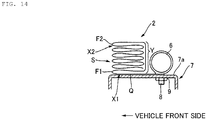
- Fig. 14 a view of a side airbag (bellows-like type) according to the modification in a stored state before deployment showing from above how the side airbag is attached to a seat frame
- Fig. 15 is a view of the side airbag according to the modification showing from above how the side airbag is deployed and inflated.
- the side airbag 2 has a folded portion X1, an additional folded portion X2 with an additional folding line F2, and a superposed portion S in series sequentially from the side of the inflator 6 to its front end in a flat spread out state. More specifically, the additional folded portion X2 is provided between the folded portion X1 and the superposed portion S.
- the superposed portion S is arranged between the additional folded portion X2 and the folded portion X1 in the vehicle-widthwise direction in the stored state before deployment because of the additional folded portion X2. More specifically, the additional folded portion X2 is positioned outside of the superposed portion S in the vehicle-widthwise direction.
- the additional folded portion X2 faces the vehicle component such as the door 4 and the console box 5.
- the superposed portion S is interposed between the additional folded portion X2 and the folded portion X1, and the additional folded portion is inflated by inflator gas introduced through the folded portion X1, supports the superposed portion S to be pushed out in the vehicle-widthwise direction by the inflation of the folded portion X1 from the opposite side (on the side of the door 4 or the console box 5) to the folded portion X1 (on the side of the inflator 6 and the seat frame 7) and thus directs the deployment and inflation direction of the superposed portion S laterally to the occupant P.
- the additional folded portion X2 is formed by setting the additional folding line F2 in a location of the superposed portion S connected to the folded portion X1.
- the additional folding line F2 causes the direction of rolling or folding the superposed portion S to be reversed from the above-described embodiment (see Fig. 9 and Fig. 10 ).
- the additional folded portion X2 is continuous to both the superposed portion S and the folded portion X1 as described above and connected to the folded portion X1 by detouring to surround almost half around the outer side of the superposed portion S from the vehicle rear side (indicated by Y).
- the folding line F1 of the folded portion X1 and the additional folding line F2 of the additional folded portion X2 are set on the same side with respect to the inflator 6 in the vehicle front-back direction.
- the additional folded portion X2 and the folded portion X1 are set in a parallel arrangement to each other in the vehicle front-back direction.
- the additional folded portion X2 may be folded to the opposite direction from the above or forward from the vehicle rear side to be specific if the superposed portion S is positioned between the additional folded portion X2 and the folded portion X1.
- the additional folded portion X2 is folded once but a plurality of such additional folded portion X2 may be formed by folding back a number of times, so that the plurality of additional folds X2 are placed upon one another.
- the additional folded portion X2 is positioned parallel to the support surface 7a of the seat frame 7 and provided in a position between the inflator 6 or the folded portion X1 and the vehicle component such as the door 4 and the console box 5.
- the folded portion X1 is inflated by inflator gas filled up inside and pushes out the superposed portion S and the additional folded portion X2 toward the door 4 (see the arrow T2) .
- the inflator gas from the folded portion X1 is further introduced into the additional folded portion X2 through the folded portion X1, and the additional folded portion X2 is inflated.
- the additional folded portion X2 is placed on the vehicle component such as the door 4 and the console box 5 and inflated in the vehicle widthwise direction or toward the support surface 7a of the seat frame 7 (toward the seat back 3a) by bearing on the vehicle component during inflation.
- the additional folded portion X2 is also arranged between the vehicle component (4, 5) and the superposed portion S in the vehicle widthwise direction, so that the additional folded portion X2 inflated toward the support surface 7a of the seat frame 7 presses the superposed portion S toward the support surface 7a of the seat frame 7 (see the arrow T3).
- the additional folded portion X2 is connected to the folded portion X1 by detouring to surround the superposed portion S from the vehicle rear side and inflated by distribution of the inflator gas, so that the superposed portion S is pushed out toward the vehicle front side from between the folded portion X1 and the additional folded portion X2 (see the arrow T4) .
- the additional folded portion X2 allows the superposed portion S to be appropriately guided toward the vehicle front side in the deployment and inflation direction.
- the entire side airbag 2 can be deployed and inflated more closely to the occupant P than the case of providing the folded portion X1 only, so that the effect of receiving the occupant P can be improved.
- the effect can be equally ensured for the vehicle side airbag device 1 provided on the side of the console box 5.
- the lower side of the side airbag 2 is deployed and inflated as indicated by the two-dot chain line Z2, and the relatively tightly rolled or folded upper side of the superposed portion or the upper side of the side airbag 2 is unfolded following the above-described movement and deployed and inflated toward the vehicle front side from the side of seat back 3a as the inflator gas is introduced.
- the lower part 2b of the side airbag 2 is deployed and inflated facing the door 4, and the upper part 2c is directed obliquely upward facing the side window or the like to be deployed and inflated similarly to the above-described embodiment. It is understood that even in the modification, the advantageous effects equal to the above-described embodiments are provided.
- Fig. 16 to Fig. 21 show a side airbag device according to a modification of the embodiment of the present invention.
- Fig. 16 is a view for illustrating a first stage of the assembling procedure of assembling a side airbag into a stored state
- Fig. 17 is a view for illustrating a second stage of the assembling procedure
- Fig. 18 is a view for illustrating a third stage of the assembling procedure
- Fig. 19 is a view for illustrating a fourth stage of the assembling procedure
- Fig. 20 is a view for illustrating a fifth stage of the assembling procedure
- Fig. 21 is a view for illustrating the process of how the side airbag according to the modification is deployed and inflated as viewed from the side.
- the following description will center on differences from the above-described embodiment.
- the side airbag 2 has its upper part 2e deployed and inflated around the side window and the door 4 as indicated by the solid line Z5 in Fig. 21 , and its lower part 2d directed obliquely downward to face the door 4 below the side window and to be deployed and inflated.
- the lower part 2d is formed to be directed obliquely downward to the front side in the vehicle front-back direction.
- the opening portion 2a of the side airbag 2 is folded back to the front end in the deployment and inflation direction (hereinafter referred to as the front end in the deployment direction) to overlap the stored position of the inflator 6 and partly placed on the upper part 2e of the side airbag 2.
- the opening portion 2a is placed on the upper part 2e of the side airbag 2 to face the support surface 7a of the seat frame 7.
- the side airbag 2 has its lower part 2d folded upward to be placed on the upper part 2e.
- the lower part 2d is placed on the upper part 2e of the side airbag 2 on the opposite side to the side on which the opening portion 2a is folded back or placed to face the vehicle component such as the door 4 and the console box 5.
- the side airbag 2 has a part on the vehicle front side ahead of the stored position of the inflator 6 (the portion to be the front end in the deployment and inflation direction) that is folded back to the rear side of the vehicle (the rear end side in the deployment and inflation direction) along the folding line F1 set at the front end of the front extended portion extended toward the vehicle front side ahead of the stored position of the inflator 6.
- the extended portion between the stored position of the inflator 6 and the folding line F1 has the abutment portion Q in abutment against the support surface 7a of the seat frame 7 positioned ahead of the inflator 6 in the vehicle front-back direction.
- the side airbag 2 attains a store state.
- the superposed portion S having an upper side wider (more loosely rolled or widely folded) than a lower side allows the upper side of the side airbag 2 to be smoothly and swiftly deployed toward the vehicle front side from the seat back 3a during deployment and inflation of the side airbag 2, so that the lower side of the superposed portion S is unfolded by the deployment of the upper side of the side airbag 3, immediately followed by the deployment of the lower side of the side airbag 2.
- the superposed portion S is deployed and inflated so that the upper side of the side airbag 2 is deployed and inflated first because of the rolled or bellows-like superposed state described above, and then the lower side of the side airbag 2 is deployed and inflated.
- the preceding upper side of the side airbag 2 is instantaneously deployed and inflated along the door 4 from the side of the seat back 3a to the vehicle front side while being pressed against the door 4 by the folded portion X1.
- the relatively tightly rolled or folded lower side of the superposed portion or the lower side of the side airbag 2 follows the movement and is unfolded as the inflator gas is introduced therein and deployed and inflated toward the vehicle front side from the side of the seat back 3a.
- the side airbag 2 has its upper part 2e deployed and inflated facing the side window and the door 4 in the vicinity and its lower part 2c directed obliquely downward to face the door 4 during deployment and inflation.
- the effects can be equally ensured for the vehicle side airbag device 1 provided on the side of the console box 5.
- the lower side of the side airbag 2 is gradually unfolded from the rolled or bellows-like shape and deployed and inflated following the deployment and inflation of the upper side of the side airbag 2, so that the side airbag 2 is directed downward during deployment and inflation.
- the side airbag 2 can be deployed and inflated downward at sufficiently satisfactory deployment speed while the property of how the side airbag 2 can be stored in the seat back 3a is secured.
- vehicle side airbag devices as described above are preferred embodiments of the present invention, and other embodiments can be carried out or implemented in various other ways.
- the invention is not limited by details of the shapes, sizes, arrangements, and the like of the components shown in the accompanying drawings unless otherwise specified herein.
- the expressions and terms herein are used for the purpose of description and should not be taken as limiting unless otherwise specified.
Landscapes
- Engineering & Computer Science (AREA)
- Mechanical Engineering (AREA)
- Aviation & Aerospace Engineering (AREA)
- Transportation (AREA)
- Air Bags (AREA)
Abstract
Description
- The present invention relates to a vehicle side airbag device capable of reducing/alleviating the movement of a deployed and inflated side airbag to jerk up the arm of an occupant and improving the occupant restraining performance.
-
PTL 1 to 3 disclose prior-art techniques related to vehicle side airbag devices, which include taking up a side airbag obliquely with respect to the vertical direction and spreading the side airbag upward in the process of deployment and inflation. - The "airbag device for side collision" disclosed in
PTL 1 is aimed to deploy an airbag quickly after detection of a side collision, and the airbag is folded into a long band shape in the deployment direction and in a spirally rolled state while its surface, which is to face the vehicle interior side wall during deployment, is positioned outside, and the airbag is adapted to be deployed forward as its outer side surface is abutted against the vehicle interior side wall and the rolled state is unfolded upon a side collision. - The "structure and method for folding an airbag" in
PTL 2 is directed to the object of providing a structure and method for folding an airbag that allows improved deployment speed and smooth deployment behavior to be obtained, and here, a head protection portion is rolled a number of times while its protection surface faces inside, the head protection portion is pushed into a chest protection portion, and at this time, part of the chest protection portion coupled to the head protection portion is pushed into the chest protection portion. - The "airbag device for side collision" disclosed in
PTL 3 is aimed to provide an airbag device for side collision capable of providing a folded airbag near an upper end of the backrest of a seat without preventing smooth inflation of the airbag, and the airbag device for side collision has the folded airbag on the upper side of the backrest of the seat. The airbag is attached and fixed to the seat frame in a plurality of locations in the vertical direction on the rear edge side and has a lower chamber upstream of inflation gas and an upper chamber provided above the front side of the lower chamber, and the airbag is stored in a folded state and adapted to project forward and deployed upward during inflation. The airbag is provided with radial folding lines around the upper part side of the lower chamber on the rear edge side, and the upper chamber and the lower chamber are folded in a sector shape and stored on the rear edge side of the lower chamber. -
- [PTL 1] Japanese Patent Application Publication No.
H8-142790 - [PTL 2] Japanese Patent Application Publication No.
H11-152004 - [PTL 3] Japanese Patent Application Publication No.
H11-180243 - A side airbag is a countermeasure against a side collision and deployed and inflated toward the vehicle front side between an occupant and a vehicle component, such as a door, that is positioned laterally to the occupant in the vehicle-widthwise direction. In the above-described background art, the side airbag is intended to spread swiftly and smoothly upward. Here, the side airbag may enter below the arm of the occupant or the arm of the occupant may be unintendedly positioned above the side airbag and directly jerked up by the side airbag in a violent, instantaneous manner, which can place an unwanted load upon the occupant and may bring the occupant into an unbalanced position, such that appropriate occupant restraining performance could not be provided.
- The present invention is devised in view of the above-described problem associated with the prior art, and it is an object of the present invention to provide a vehicle side airbag device capable of reducing/alleviating the movement of a deployed and inflated airbag to jerk up the arm of an occupant and improving the occupant restraining performance.
- A vehicle side airbag device according to the present invention includes a side airbag provided inside a vehicle seat and allowed to be deployed and inflated from the seat into between an occupant and a vehicle component positioned laterally to the occupant in a vehicle-widthwise direction and an inflator attachable to a seat frame of the seat and causing inflator gas to be introduced into the side airbag, the inflator is stored inside the side airbag near a rear end thereof in a deployment and inflation direction, in a spread state, the side airbag has a folded portion with a folding line and a superposed portion in series sequentially from a side of the inflator to a front end thereof in the deployment and inflation direction, in a stored state before deployment, the folded portion is formed to include an abutment portion folded back to a vehicle rear side from a vehicle front side and abutted against the seat frame during attachment to the seat on a front side of the inflator in a vehicle front-back direction, the superposed portion is formed to be superposed in a rolled state or folded in a bellows-like state to have a lower part wider than an upper part in an up-down direction, and the folded portion is folded to be arranged between the seat frame and the superposed portion in the vehicle-widthwise direction.
- The folded portion is preferably configured to be capable of pushing out the superposed portion toward the vehicle component in the vehicle-widthwise direction upon receiving reaction force from the seat frame during deployment and inflation of the side airbag.
- A vehicle side airbag device according to the present invention includes a side airbag provided inside a vehicle seat and allowed to be deployed and inflated from the seat into between an occupant and a vehicle component positioned laterally to the occupant in a vehicle-widthwise direction and an inflator attachable to a seat frame of the seat and causing inflator gas to be introduced into the side airbag, the inflator is stored inside the side airbag near a rear end thereof in a deployment and inflation direction, in a spread state, the side airbag has a folded portion with a folding line and a superposed portion in series sequentially from a side of the inflator to a front end thereof in the deployment and inflation direction, in a stored state before deployment, the folded portion is formed to include an abutment portion folded back to a vehicle rear side from a vehicle front side and abutted against the seat frame during attachment to the seat on a front side of the inflator in a vehicle front-back direction, the superposed portion is formed to be superposed in a rolled state or folded in a bellows-like state to have an upper part wider than a lower part in an up-down direction, and the folded portion is folded to be arranged between the seat frame and the superposed portion in the vehicle-widthwise direction.
- The folded portion is preferably configured to be capable of pushing out the superposed portion toward the vehicle component in the vehicle-widthwise direction upon receiving reaction force from the seat frame during deployment and inflation of the side airbag.
- The vehicle component is desirably a vehicle door or a console box provided on a center side in the vehicle in the vehicle-widthwise direction.
- The side airbag is preferably folded to have an upper part in the up-down direction placed on a lower part before the folded portion and the superposed portion are formed.
- Desirably, the side airbag has an additional folded portion with an additional folding line between the folded portion and the superposed portion; in a stored state before deployment, the additional folded portion is formed to be folded back at least once along the additional folding line to the vehicle rear side from the vehicle front side or conversely in an arrangement parallel to the folded portion; and the superposed portion is arranged between the additional folded portion and the folded portion in the vehicle-widthwise direction.
- In the vehicle side airbag device according to the present invention, the movement of a deployed and inflated side airbag to jerk up the arm of an occupant can be reduced/alleviated and the occupant restraining performance can be improved.
-
- [
Fig. 1 ]
Fig. 1 is a plan view of a vehicle side airbag device according to a preferred embodiment of the present invention showing from above a side airbag in an inflated and deployed state. - [
Fig. 2 ]
Fig. 2 is a view for illustrating a first stage of the assembling procedure of assembling a side airbag into a stored state. - [
Fig. 3 ]
Fig. 3 is a view for illustrating a second stage of the assembling procedure. - [
Fig. 4 ]
Fig. 4 is a view for illustrating a third stage of the assembling procedure. - [
Fig. 5 ]
Fig. 5 is a view for illustrating a fourth stage of the assembling procedure. - [
Fig. 6 ]
Fig. 6 is a view for illustrating a fifth stage of the assembling procedure. - [
Fig. 7 ]
Fig. 7 is a schematic view for illustrating the first half of the assembling procedure described above. - [
Fig. 8 ]
Fig. 8 is a schematic view for illustrating the second half of the assembling procedure described above. - [
Fig. 9 ]
Fig. 9 is a plan view of the side airbag (rolled type) shown inFig. 1 in a stored state before deployment showing from above how the side airbag is attached to a seat frame. - [
Fig. 10 ]
Fig. 10 is a plan view of the side airbag (bellows-like type) shown inFig. 1 in a stored state before deployment showing from above how the side airbag is attached to the seat frame. - [
Fig. 11 ]
Fig. 11 is a view for illustrating how the side airbag shown inFig. 1 is inflated and deployed as viewed from above. - [
Fig. 12 ]
Fig. 12 is a view for illustrating the process of the deployment and inflation of the side airbag shown inFig. 11 as viewed from the side. - [
Fig. 13 ]
Fig. 13 is a plan view of a modification of the vehicle side airbag device according to the present invention showing from above a side airbag (rolled type) in a stored state before deployment and how the side airbag is attached to a seat frame. - [
Fig. 14 ]
Fig. 14 is a plan view of the modification of the vehicle side airbag device according to the present invention showing from above a side airbag (bellows-like type) in a stored state before deployment and how the side airbag is attached to a seat frame. - [
Fig. 15 ]
Fig. 15 is a view for illustrating how the side airbag in the modification of the vehicle side airbag device according to the present invention is deployed and inflated as viewed from above. - [
Fig. 16 ]
Fig. 16 is a view of another modification of the vehicle side airbag according to the present invention for illustrating a first stage of the assembling procedure of assembling a side airbag into a stored state. - [
Fig. 17 ]
Fig. 17 is a view for illustrating a second stage of the procedure of assembling the side airbag shown inFig. 16 . - [
Fig. 18 ]
Fig. 18 is a view for illustrating a third stage of the procedure of assembling the side airbag shown inFig. 16 . - [
Fig. 19 ]
Fig. 19 is a view for illustrating a fourth stage of the procedure of assembling the side airbag shown inFig. 16 . - [
Fig. 20 ]
Fig. 20 is a view for illustrating a fifth stage of the procedure of assembling the side airbag shown inFig. 16 . - [
Fig. 21 ]
Fig. 21 is a view of the side airbag inFig. 16 in the process of deployment and inflation as viewed from the side. - Hereinbelow, a vehicle side airbag device according to a preferred embodiment of the present invention will be described in detail with reference to the accompanying drawings.
Fig. 1 is a plan view of a side airbag in a vehicle side airbag device according to the embodiment in a deployed and inflated state as viewed from above,Fig. 2 is a view for illustrating a first stage of the assembling procedure of assembling the side airbag shown inFig. 1 into a stored state,Fig. 3 is a view for illustrating a second stage of the assembling procedure,Fig. 4 is a view for illustrating a third stage of the assembling procedure,Fig. 5 is a view for illustrating a fourth stage of the assembling procedure,Fig. 6 is a view for illustrating a fifth stage of the assembling procedure,Fig. 7 is a schematic view for illustrating the first half of the assembling procedure described above,Fig. 8 is a schematic view for illustrating the second half of the assembling procedure described above,Fig. 9 is a plan view of the side airbag (rolled type) shown inFig. 1 in a stored state before deployment showing from above how the side airbag is attached to a seat frame,Fig. 10 is a plan view of the side airbag (bellows-like type) shown inFig. 1 in a stored state before deployment showing from above how the side airbag is attached to the seat frame,Fig. 11 is a view for illustrating how the side airbag shown inFig. 1 is inflated and deployed as viewed from above, andFig. 12 is a view for illustrating the side airbag shown inFig. 11 in the process of the deployment and inflation as viewed from the side. - As shown in
Fig. 1 , aside airbag 2 in a vehicleside airbag device 1 is provided inside a seat back 3a of aseat 3 provided in a vehicle as the airbag is stored in a rolled up or collapsed state before deployment and inflation. An occupant P is seated at theseat 3. On both the left and right sides of theseat 3 in the vehicle-widthwise direction, vehicle components such as a door 4 (on the vehicle exterior side) and a console box 5 (on the vehicle interior side) on the center side in the vehicle-widthwise direction are provided in lateral positions to the occupant P in the vehicle-widthwise direction, in other words, in positions facing the sides of the occupant P. - As has been well known, in response to an impact upon the vehicle caused by a side collision for example, the
side airbag 2 is deployable and inflatable from the seat back 3a to the front side of theseat 3, in other words, forward in the front-back lengthwise direction of the vehicle (hereinafter as the vehicle front-back direction), into between the occupant P and the vehicle component such as thedoor 4 and theconsole box 5 positioned laterally to the occupant P in the vehicle-widthwise direction. Therefore, as shown inFig. 2 , the part of theside airbag 2 on the side of the seat back 3a (the vehicle rear side) corresponds to the rear end side in the deployment and inflation direction, and the vehicle front side corresponds to the front end side in the deployment and inflation direction. - The deployment and inflation of the
side airbag 2 from its stored state is achieved by introduction of inflator gas from aninflator 6 into theside airbag 2. Theside airbag 2 is normally deployed and inflated in a range from the hips of the occupant P to above the head, restrains the occupant P toward theseat 3, blocks the vehicle component such as thedoor 4 from the occupant P to protect the occupant P, and reduces the injury value for the occupant P. - A
firm seat frame 7 for receiving and supporting the body of the occupant P or the like resting thereupon is provided in the seat back 3a. As shown inFig. 9 , theseat frame 7 is a frame including a channel member or a square tube. Theseat frame 7 has a plane portion facing the side of the vehicle component such as thedoor 4, and according to the embodiment, the plane portion forms asupport surface 7a used to attach theinflator 6 or support theside airbag 2 to be deployed and inflated. Therefore, theinflator 6 can be attached to theseat 3, for example at theseat frame 7. -
Stud bolts 8 are provided integrally on one side of theinflator 6 and fixed bynuts 9 to thesupport surface 7a of theseat frame 7 inside the seat back 3a. Theinflator 6 is attached to thesupport surface 7a of theseat frame 7 as thestud bolts 8 are fixed to theseat frame 7. Theinflator 6 is stored in theside airbag 2. The storing position of theinflator 6 is set near the rear end of theside airbag 2 in the deployment and inflation direction. - The
inflator 6 stored in theside airbag 2 is attached to theseat frame 7, so that the part of theside airbag 2 near the rear end in the deployment and inflation direction is fixed to theseat frame 7. Since theinflator 6 is stored in theside airbag 2, inflator gas ejected from theinflator 6 fills up theside airbag 2 to deploy and inflate theside airbag 2. - Now, the assembling procedure of assembling the
side airbag 2 into a stored state will be described.Fig. 2 shows theside airbag 2 in a flat spread out state. In the figure, the upward direction corresponds to the upward direction in the vehicle up-down height-wise direction (hereinafter referred to as the height-wise direction), the downward direction corresponds to the downward direction in the height-wise direction, the leftward corresponds to the front end side in the deployment and inflation direction (the vehicle front side), and the rightward corresponds to the rear end side in the deployment and inflation direction (the vehicle rear side). - In a well-known manner, the
side airbag 2 is formed into a bag shape having an openingportion 2a by placing two sheets of ground fabric on each other or folding a sheet of ground fabric and placing the folds upon each other and then stitching the peripheries together to join them. - In the illustrated
side airbag 2, theopening portion 2a is formed to protrude to the vehicle rear side toward the rear end in the deployment and inflation direction (hereinafter referred to as the rear end in the deployment direction). Theinflator 6 is stored inside theside airbag 2 through theopening portion 2a. Thestud bolts 8 protrude outwardly from theside airbag 2 through bolt holes formed at theside airbag 2. Note that 10 designates a harness. - According to the embodiment, the external shape of the
side airbag 2 has a larger size in the vehicle up-down direction than its length in the vehicle front-back direction. Theside airbag 2 is generally directed obliquely upward from the storing position of theinflator 6 to the front side in the vehicle front-back direction. - Stated differently, when the
side airbag 2 is observed as it is separated in the height-wise direction into alower part 2b corresponding to a height-wise range in which theinflator 6 is stored (which corresponds to the height of the door belt line and its vicinity in the vehicle) and anupper part 2c corresponding to a height-wise range beyond the inflator 6 (which corresponds to the side window position in the vehicle), theupper part 2c is formed to be directed obliquely upward to the front side in the vehicle front-back direction. - If the
side airbag 2 is formed into this shape, the region from the hips to the head of the occupant P that can move forward in the vehicle and outward in the vehicle-widthwise direction upon a side collision or the like can be received and restrained by theentire side airbag 2 and protected. - Then, as shown in
Fig. 3 , theopening portion 2a of theside airbag 2 is folded back to the front end in the deployment and inflation direction (hereinafter referred to as the front end in the deployment direction) and is partly placed on thelower part 2b of theside airbag 2 so that the opening portion overlaps the storing position of theinflator 6. Theopening portion 2a has throughholes 11 through which thestud bolts 8 protruding from theside airbag 2 are passed (seeFig. 2 ). Therefore, theopening portion 2a is placed on thelower part 2b of theside airbag 2 to face thesupport surface 7a of theseat frame 7. - Then, as shown in
Fig. 4 , theside airbag 2 is folded downward so that theupper part 2c is placed on thelower part 2b. In the illustrated example, theupper part 2c is placed on thelower part 2b of theside airbag 2 on the opposite side to the side to which theopening portion 2a is folded, in other words, the upper part is placed to face the vehicle component such as thedoor 4 and theconsole box 5. In this way, theside airbag 2 in an external shape having a larger size in the height-wise direction can be stored in a compact shape with a reduced height. - Then, as shown in
Fig. 5 , the part of theside airbag 2 on the vehicle front side ahead of the storing position of the inflator 6 (the part to be the front end in the deployment and inflation direction) is folded back to the vehicle rear side (the rear end side in the deployment and inflation direction) along a folding line F1 set at the front end of the front extended part extended to the vehicle front side beyond the stored position of theinflator 6. An abutment portion Q in abutment against thesupport surface 7a of theseat frame 7 is set at the extended portion from the stored position of theinflator 6 to the folding line F1 on the vehicle front side of theinflator 6 in the vehicle front-back direction. - For the ease of description, the description will continue with reference to
Fig. 7 andFig. 8 showing theside airbag 2 in a rectangular shape having a greater length in the vehicle front-back direction.Fig. 7(a) substantially corresponds toFig. 2 andFig. 3 and shows theside airbag 2 storing theinflator 6 in a flat spread out state. In the following description, the manner of folding theupper part 2c of theside airbag 2 on thelower part 2b described in conjunction withFig. 4 is omitted. - In the flat spread out state, the
side airbag 2 has a folded portion X1 with a folding line F1 and a superposed portion S rolled or folded in a bellows-like shape in series sequentially from the side of the inflator 6 (on the rear end side in the deployment direction) to the front end in the deployment direction. - To be more specific, the folded portion X1 corresponds to a region folded along the folding line F1 at the front end of the front extended portion from the stored position of the
inflator 6, and the front extended portion that forms the folded portion X1 includes the abutment portion Q in abutment against theseat frame 7 or thesupport surface 7a of theseat frame 7 to be specific when theside airbag 2 is attached to theseat 3. -
Fig. 7 (b-1) corresponds toFig. 5 . As described in conjunction withFig. 5 , the position of the folding line F1 is set on the vehicle front side ahead of the stored position of theinflator 6. In the illustrated example of theside airbag 2, the airbag is folded back to the vehicle rear side from the vehicle front side along the folding line F1 on the front side of theinflator 6 in the vehicle front-back direction, so that the entire side airbag is extended to the rear side of the vehicle excluding the abutment portion Q. - The folded portion X1 is provided in a location between the
support surface 7a of theseat frame 7 and the vehicle component such as thedoor 4 and theconsole box 5. In the meantime, the superposed portion S is extended on the vehicle rear side behind the folded portion X1 by the folding line F1. When the folding line F1 is set on the vehicle rear side behind the storing position of theinflator 6 and theside airbag 2 is folded to the vehicle front side from the vehicle rear side, the superposed portion S is extended to the vehicle front side ahead of the folded portion X1. - In the illustrated example, the folding line F1 is formed slightly obliquely with respect to the vehicle front-back direction so that the upper end side of the
side airbag 2 in the height-wise direction is folded in a position more on the vehicle rear side and the lower end side in the height-wise direction is folded in a position more on the vehicle front side. In this way, the superposed portion S has a substantially trapezoidal outer shape. - When the folded
side airbag 2 is observed from above, the superposed portion S continuous with the folded portion X1 is positioned to overlap theinflator 6 in theside airbag 2 as shown inFig. 7 (b-2). - The superposed portion S is superposed in a rolled state or folded in a bellows-like state. As shown in
Fig. 7(c) , as for the shape of the superposed portion S, the circumference D for taking up or the interval D for folding is reduced on the upper side of theside airbag 2 and widened on the lower side so that the lower side of theside airbag 2 in the height-wise direction is wider than the upper side during superposition. - Therefore, as shown in
Fig. 8(a) , when theside airbag 2 is in a stored state after the superposed portion S is formed, the superposed portion S is placed on the abutment portion Q of the folded portion X1 in the vehicle-widthwise direction, while as shown inFig. 8(b) , when the superposed portion S is in a rolled state, the upper side has a small radius (R1), and the lower side is loosely rolled to have a large radius (R2) as shown inFig. 8 (c) and Fig. 8(d) , so that the side airbag is formed into a circular truncated cone (cone shape) tapered upward and made longer in the vertical direction. As can be understood from the stored state, theside airbag 2 has, in series, an extended portion extended generally flatly from the stored position of theinflator 6 and including the abutment portion Q, the folding line F1 at the front end of the extended portion, and the superposed portion S extended from the folding line F1 to the front end in the deployment and inflation direction, so that the superposed portion S is placed on the extended portion (abutment portion Q) by the folding line F1 virtually along the folding line F1 as the boundary. - When the superposed portion S is folded in a bellows-like shape, the upper side is narrow (W1) and the lower side is wide (W2) as shown in
Fig. 8(e) , so that the portion is formed into a trapezoidal shape tapered upward and made longer in the vertical direction. - When the length from the
inflator 6 to the folding line F1 is shorter than the above-described larger sizes (R2 and W2) of the superposed portion S and the folded portion X1 is deployed and inflated, the superposed portion S might roll and fall off from thesupport surface 7a rather than in the vehicle-widthwise direction. Therefore, the length from theinflator 6 to the folding line F1 is preferably set to about the same size as the above-described sizes (R2 and W2) of the superposed portion S. - As in the foregoing, the
side airbag 2 is arranged in the stored state as shown inFig. 6 that corresponds toFig. 8(a) . The superposed portion S that is wider on the lower side (which is loosely rolled or widely folded) than the upper side allows the lower side of theside airbag 2 to be smoothly and swiftly deployed from the seat back 3a toward the vehicle front side during deployment and inflation of theside airbag 2, so that the upper side of the superposed portion S is unfolded by the deployment of the lower side of theside airbag 3, immediately followed by deployment of the upper side of theside airbag 2. - As shown in
Fig. 9 andFig. 10 , theside airbag 2 in the stored state is provided in the seat back 3a by fixing thestud bolts 8 of theinflator 6 to theseat frame 7 and attaching theinflator 6 to theseat frame 7. In the stored state of theside airbag 2 having theinflator 6 provided inside, the folded portion X1 is arranged between thesupport surface 7a of theseat frame 7 and the superposed portion S while it is directed in the vehicle-widthwise direction in which the vehicle component such as thedoor 4 and theconsole box 5 is positioned. More specifically, the folded portion X1 is folded to be arranged between theseat frame 7 and the superposed portion S in the vehicle-widthwise direction. - The folded portion X1 is configured to be capable of pushing out the superposed portion S toward the vehicle component such as the
door 4 and theconsole box 5 in the vehicle-widthwise direction upon receiving reaction force from theseat frame 7 during deployment and inflation of theside airbag 2. Stated differently, the folded portion X1 is configured to be inflated at thesupport surface 7a of theseat frame 7 by introduced inflator gas and push out the superposed portion S toward the vehicle component such as thedoor 4 and theconsole box 5 in the vehicle-widthwise direction. - Now, the operation of the vehicle
side airbag device 1 according to the embodiment will be described. The following description is about the operation on the side of thedoor 4 but equally applies to the operation on the side of theconsole box 5. - As shown in
Fig. 11 andFig. 12 , theside airbag 2 that stores theinflator 6 attached to thesupport surface 7a of theseat frame 7 using thestud bolts 8 is provided in a stored state inside the seat back 3a. Theinflator 6 is activated in response to a side collision for example to eject inflator gas into theside airbag 2, and then theside airbag 2 is made to jump out through the opening formed at the seat back 3a and deployed and inflated. - In an initial stage of the deployment and inflation of the
side airbag 2, the folded portion X1 folded along the folding line F1 is filled up with the inflator gas. The folded portion X1 has the abutment portion Q placed on thesupport surface 7a of theseat frame 7 and is inflated in the vehicle-widthwise direction or toward the side of thedoor 4 as the vehicle component as the portion bears on thesupport surface 7a during inflation. - The folded portion X1 is also positioned between the
support surface 7a of theseat frame 7 and the superposed portion S in the vehicle-widthwise direction, and therefore the folded portion X1 inflated toward thedoor 4 as indicated by the single-dot chain line Z1 pushes out the superposed portion S toward the door 4 (see the arrow T1). - The inflator gas introduced into the folded portion X1 is further introduced into the superposed portion S. The superposed portion S is deployed and inflated by the introduced inflator gas while being pressed against the
door 4 by the folded portion X1. The lower side of theside airbag 2 precedes the upper side of theside airbag 2 in the deployment and inflation of the superposed portion S because of the rolled or bellows-like superposed state. - The preceding lower side of the
side airbag 2 is instantaneously deployed and inflated to the vehicle front side from the side of the seat back 3a along thedoor 4 while being pressed against thedoor 4 by the folded portion X1. As indicated by the two-dot chain line Z2, when the lower side of theside airbag 2 is deployed and inflated, the relatively tightly rolled or folded upper side of the superposed portion or the upper side of theside airbag 2 is unfolded in response to the movement to be deployed and inflated to the vehicle front side from the side of the seat back 3a as the inflator gas is introduced. - A shown in
Fig. 4 , when theupper part 2c of theside airbag 2 in the up-down direction is folded and placed on thelower part 2b before the folded portion X1 and the superposed portion S are formed, theupper part 2c is deployed and inflated more upward than thelower part 2b in the process of deployment and inflation of the superposed portion S. - Therefore, as indicated by the solid line Z3, the
lower part 2b of theside airbag 2 is deployed and inflated facing thedoor 4 and theupper part 2c is directed obliquely upward during deployment and inflation so that theupper part 2c faces the side window or the like. The operation can be similarly ensured for the vehicleside airbag device 1 provided on the side of theconsole box 5. - As described in conjunction of the background art, as the
side airbag 2 is deployed and inflated, the side airbag could enter below the arm of an occupant or the arm of an occupant could be unintendedly positioned above the side airbag, and the arm of the occupant could be violently and instantaneously jerked up by the side airbag. - In contrast, in the vehicle
side airbag device 1 according to embodiment, the superposed portion S deployed and inflated to the vehicle front side is pushed out and pressed against thedoor 4 or theconsole box 5 by the folded portion X1, so that the superposed portion S can be deployed and inflated to the vehicle front side while avoiding the position of the arm of the occupant P. - Since the upper side of the
side airbag 2 is gradually unfolded to be deployed and inflated from the rolled or bellows-like folded state succeeding the deployment and inflation of the lower side of theside airbag 2, so that the superposed portion S lifts up the arm of the occupant P rather than violently and instantaneously jerking up the arm of the occupant P and theside airbag 2 can be directed obliquely upward during deployment and inflation. - Therefore, appropriate occupant restraining performance can be ensured without placing an unwanted load upon the occupant P and bringing the occupant P into an unbalanced position. The
side airbag 2 can be deployed and inflated in a height range from the hips of the occupant P to above the head and receive the chest and side of the occupant P from under the lifted arm to surely restrain the occupant P to the side of theseat 3, while at the same blocking and protecting the occupant P from the vehicle component such as thedoor 4 and theconsole box 5, so that the injury value for the occupant P can be reduced. - As in the foregoing, the vehicle
side airbag device 1 according to the embodiment can alleviate and reduce the movement of theside airbag 2 to jerk up the arm of the occupant P during deployment and inflation, so that the occupant restraining performance can be improved. -
Fig. 13 to Fig. 15 show a modification of the above-described embodiment.Fig. 13 is a view of a side airbag (rolled type) according to the modification in a stored state before deployment showing from above how the side airbag is attached to a seat frame,Fig. 14 a view of a side airbag (bellows-like type) according to the modification in a stored state before deployment showing from above how the side airbag is attached to a seat frame, andFig. 15 is a view of the side airbag according to the modification showing from above how the side airbag is deployed and inflated. - As shown in
Fig. 13 and14 , according to the modification, theside airbag 2 has a folded portion X1, an additional folded portion X2 with an additional folding line F2, and a superposed portion S in series sequentially from the side of theinflator 6 to its front end in a flat spread out state. More specifically, the additional folded portion X2 is provided between the folded portion X1 and the superposed portion S. - The superposed portion S is arranged between the additional folded portion X2 and the folded portion X1 in the vehicle-widthwise direction in the stored state before deployment because of the additional folded portion X2. More specifically, the additional folded portion X2 is positioned outside of the superposed portion S in the vehicle-widthwise direction. The additional folded portion X2 faces the vehicle component such as the
door 4 and theconsole box 5. - The superposed portion S is interposed between the additional folded portion X2 and the folded portion X1, and the additional folded portion is inflated by inflator gas introduced through the folded portion X1, supports the superposed portion S to be pushed out in the vehicle-widthwise direction by the inflation of the folded portion X1 from the opposite side (on the side of the
door 4 or the console box 5) to the folded portion X1 (on the side of theinflator 6 and the seat frame 7) and thus directs the deployment and inflation direction of the superposed portion S laterally to the occupant P. - The additional folded portion X2 is formed by setting the additional folding line F2 in a location of the superposed portion S connected to the folded portion X1. The additional folding line F2 causes the direction of rolling or folding the superposed portion S to be reversed from the above-described embodiment (see
Fig. 9 andFig. 10 ). The additional folded portion X2 is continuous to both the superposed portion S and the folded portion X1 as described above and connected to the folded portion X1 by detouring to surround almost half around the outer side of the superposed portion S from the vehicle rear side (indicated by Y). - The folding line F1 of the folded portion X1 and the additional folding line F2 of the additional folded portion X2 are set on the same side with respect to the
inflator 6 in the vehicle front-back direction. The additional folded portion X2 and the folded portion X1 are set in a parallel arrangement to each other in the vehicle front-back direction. - The additional folded portion X2 may be folded to the opposite direction from the above or forward from the vehicle rear side to be specific if the superposed portion S is positioned between the additional folded portion X2 and the folded portion X1. In the illustrated example, the additional folded portion X2 is folded once but a plurality of such additional folded portion X2 may be formed by folding back a number of times, so that the plurality of additional folds X2 are placed upon one another.
- The additional folded portion X2 is positioned parallel to the
support surface 7a of theseat frame 7 and provided in a position between the inflator 6 or the folded portion X1 and the vehicle component such as thedoor 4 and theconsole box 5. - As indicated by the single-dot chain line Z1 in
Fig. 15 , in an early stage of the deployment and inflation of theside airbag 2, the folded portion X1 is inflated by inflator gas filled up inside and pushes out the superposed portion S and the additional folded portion X2 toward the door 4 (see the arrow T2) . The inflator gas from the folded portion X1 is further introduced into the additional folded portion X2 through the folded portion X1, and the additional folded portion X2 is inflated. - The additional folded portion X2 is placed on the vehicle component such as the
door 4 and theconsole box 5 and inflated in the vehicle widthwise direction or toward thesupport surface 7a of the seat frame 7 (toward the seat back 3a) by bearing on the vehicle component during inflation. The additional folded portion X2 is also arranged between the vehicle component (4, 5) and the superposed portion S in the vehicle widthwise direction, so that the additional folded portion X2 inflated toward thesupport surface 7a of theseat frame 7 presses the superposed portion S toward thesupport surface 7a of the seat frame 7 (see the arrow T3). - Furthermore, the additional folded portion X2 is connected to the folded portion X1 by detouring to surround the superposed portion S from the vehicle rear side and inflated by distribution of the inflator gas, so that the superposed portion S is pushed out toward the vehicle front side from between the folded portion X1 and the additional folded portion X2 (see the arrow T4) .
- In the modification, the additional folded portion X2 allows the superposed portion S to be appropriately guided toward the vehicle front side in the deployment and inflation direction. The
entire side airbag 2 can be deployed and inflated more closely to the occupant P than the case of providing the folded portion X1 only, so that the effect of receiving the occupant P can be improved. The effect can be equally ensured for the vehicleside airbag device 1 provided on the side of theconsole box 5. - Then, when the inflator gas is introduced into the superposed portion S from the additional folded portion X2, the lower side of the
side airbag 2 is deployed and inflated as indicated by the two-dot chain line Z2, and the relatively tightly rolled or folded upper side of the superposed portion or the upper side of theside airbag 2 is unfolded following the above-described movement and deployed and inflated toward the vehicle front side from the side of seat back 3a as the inflator gas is introduced. - Then, as indicated by the solid line Z3, the
lower part 2b of theside airbag 2 is deployed and inflated facing thedoor 4, and theupper part 2c is directed obliquely upward facing the side window or the like to be deployed and inflated similarly to the above-described embodiment. It is understood that even in the modification, the advantageous effects equal to the above-described embodiments are provided. -
Fig. 16 to Fig. 21 show a side airbag device according to a modification of the embodiment of the present invention.Fig. 16 is a view for illustrating a first stage of the assembling procedure of assembling a side airbag into a stored state,Fig. 17 is a view for illustrating a second stage of the assembling procedure,Fig. 18 is a view for illustrating a third stage of the assembling procedure,Fig. 19 is a view for illustrating a fourth stage of the assembling procedure,Fig. 20 is a view for illustrating a fifth stage of the assembling procedure, andFig. 21 is a view for illustrating the process of how the side airbag according to the modification is deployed and inflated as viewed from the side. The following description will center on differences from the above-described embodiment. - According to the modification, the
side airbag 2 has itsupper part 2e deployed and inflated around the side window and thedoor 4 as indicated by the solid line Z5 inFig. 21 , and itslower part 2d directed obliquely downward to face thedoor 4 below the side window and to be deployed and inflated. - As shown in
Fig. 16 , when theside airbag 2 is observed as it is separated in the height-wise direction into theupper part 2e corresponding to the height-wise range in which theinflator 6 is stored (which corresponds to the height of the vehicle door belt line and the vicinity) and thelower part 2d corresponding to the height-wise range below the inflator 6 (which corresponds to the position of the vehicle door 4), thelower part 2d is formed to be directed obliquely downward to the front side in the vehicle front-back direction. - As shown in
Fig. 17 , theopening portion 2a of theside airbag 2 is folded back to the front end in the deployment and inflation direction (hereinafter referred to as the front end in the deployment direction) to overlap the stored position of theinflator 6 and partly placed on theupper part 2e of theside airbag 2. Theopening portion 2a is placed on theupper part 2e of theside airbag 2 to face thesupport surface 7a of theseat frame 7. - Then, as shown in
Fig. 18 , theside airbag 2 has itslower part 2d folded upward to be placed on theupper part 2e. In the illustrated example, thelower part 2d is placed on theupper part 2e of theside airbag 2 on the opposite side to the side on which theopening portion 2a is folded back or placed to face the vehicle component such as thedoor 4 and theconsole box 5. - Then, as shown in
Fig. 19 , theside airbag 2 has a part on the vehicle front side ahead of the stored position of the inflator 6 (the portion to be the front end in the deployment and inflation direction) that is folded back to the rear side of the vehicle (the rear end side in the deployment and inflation direction) along the folding line F1 set at the front end of the front extended portion extended toward the vehicle front side ahead of the stored position of theinflator 6. The extended portion between the stored position of theinflator 6 and the folding line F1 has the abutment portion Q in abutment against thesupport surface 7a of theseat frame 7 positioned ahead of theinflator 6 in the vehicle front-back direction. - Then, as shown in
Fig. 20 , after the procedure described in conjunction withFig. 7 andFig. 8 related to the above-described embodiment, theside airbag 2 attains a store state. The superposed portion S having an upper side wider (more loosely rolled or widely folded) than a lower side allows the upper side of theside airbag 2 to be smoothly and swiftly deployed toward the vehicle front side from the seat back 3a during deployment and inflation of theside airbag 2, so that the lower side of the superposed portion S is unfolded by the deployment of the upper side of theside airbag 3, immediately followed by the deployment of the lower side of theside airbag 2. - In the deploying and inflating behavior according to the modification, the superposed portion S is deployed and inflated so that the upper side of the
side airbag 2 is deployed and inflated first because of the rolled or bellows-like superposed state described above, and then the lower side of theside airbag 2 is deployed and inflated. - The preceding upper side of the
side airbag 2 is instantaneously deployed and inflated along thedoor 4 from the side of the seat back 3a to the vehicle front side while being pressed against thedoor 4 by the folded portion X1. As indicated by the two-dot chain line Z4, when the upper side of theside airbag 2 is deployed and inflated, the relatively tightly rolled or folded lower side of the superposed portion or the lower side of theside airbag 2 follows the movement and is unfolded as the inflator gas is introduced therein and deployed and inflated toward the vehicle front side from the side of the seat back 3a. - As shown in
Fig. 18 , when thelower part 2d in the up-down direction of theside airbag 2 is folded to be placed on theupper part 2e before the folded portion X1 and the superposed portion S are formed, thelower part 2d is deployed and inflated upward with relative to theupper part 2e in the process of deployment and inflation of the superposed portion S. - Therefore, as indicated by the solid line Z5, the
side airbag 2 has itsupper part 2e deployed and inflated facing the side window and thedoor 4 in the vicinity and itslower part 2c directed obliquely downward to face thedoor 4 during deployment and inflation. The effects can be equally ensured for the vehicleside airbag device 1 provided on the side of theconsole box 5. - As for the superposed portion S, the lower side of the
side airbag 2 is gradually unfolded from the rolled or bellows-like shape and deployed and inflated following the deployment and inflation of the upper side of theside airbag 2, so that theside airbag 2 is directed downward during deployment and inflation. - According to the modification, the
side airbag 2 can be deployed and inflated downward at sufficiently satisfactory deployment speed while the property of how theside airbag 2 can be stored in the seat back 3a is secured. - It is understood that even in the modification, the advantageous effects equal to the above-described embodiment can be provided.
- The vehicle side airbag devices as described above are preferred embodiments of the present invention, and other embodiments can be carried out or implemented in various other ways. In particular, the invention is not limited by details of the shapes, sizes, arrangements, and the like of the components shown in the accompanying drawings unless otherwise specified herein. The expressions and terms herein are used for the purpose of description and should not be taken as limiting unless otherwise specified.
-
- 1
- Vehicle side airbag device
- 2
- Side airbag
- 2b
- Lower part of side airbag
- 2c
- Upper part of side airbag
- 2d
- Lower part of side airbag
- 2e
- Upper part of side airbag
- 3
- Seat
- 4
- Door
- 5
- Console box
- 6
- Inflator
- 7
- Seat frame
- 7a
- Support surface
- F1
- Folding line
- F2
- Additional folding line
- P
- Occupant
- Q
- Abutment portion
- S
- Superposed portion
- X1
- Folded portion
- X2
- Additional folded portion
Claims (8)
- A vehicle side airbag device, comprising:a side airbag provided inside a vehicle seat and allowed to be deployed and inflated from the seat into between an occupant and a vehicle component positioned laterally to the occupant in a vehicle-widthwise direction; andan inflator attachable to a seat frame of the seat and causing inflator gas to be introduced into the side airbag,the inflator being stored inside the side airbag near a rear end thereof in a deployment and inflation direction,in a spread state, the side airbag having a folded portion with a folding line and a superposed portion in series sequentially from a side of the inflator to a front end thereof in the deployment and inflation direction, in a stored state before deployment, the folded portion being formed to include an abutment portion folded back to a vehicle rear side from a vehicle front side and abutted against the seat frame during attachment to the seat on a front side of the inflator in a vehicle front-back direction, the superposed portion being formed to be superposed in a rolled state or collapsed in a bellows-like state to have a lower part wider than an upper part in an up-down direction,the folded portion being folded to be arranged between the seat frame and the superposed portion in the vehicle-widthwise direction.
- The vehicle side airbag device of claim 1, wherein the folded portion is configured to be capable of pushing out the superposed portion toward the vehicle component in the vehicle-widthwise direction upon receiving reaction force from the seat frame during deployment and inflation of the side airbag.
- A vehicle side airbag device, comprising:a side airbag provided inside a vehicle seat and allowed to be deployed and inflated from the seat into between an occupant and a vehicle component positioned laterally to the occupant in a vehicle-widthwise direction; andan inflator attachable to a seat frame of the seat and causing inflator gas to be introduced into the side airbag,the inflator being stored inside the side airbag near a rear end thereof in a deployment and inflation direction,in a spread state, the side airbag having a folded portion with a folding line and a superposed portion in series sequentially from a side of the inflator to a front end thereof in the deployment and inflation direction, in a stored state before deployment, the folded portion being formed to include an abutment portion folded back to a vehicle rear side from a vehicle front side and abutted against the seat frame during attachment to the seat on a front side of the inflator in a vehicle front-back direction, the superposed portion being formed to be superposed in a rolled state or collapsed in a bellows-like state to have an upper part wider than a lower part in an up-down direction,the folded portion being folded to be arranged between the seat frame and the superposed portion in the vehicle-widthwise direction.
- The vehicle side airbag device of claim 1, wherein the folded portion is configured to be capable of pushing out the superposed portion toward the vehicle component in the vehicle-widthwise direction upon receiving reaction force from the seat frame during deployment and inflation of the side airbag.
- The vehicle side airbag device of any one of claims 1 to 4, wherein the vehicle component is a vehicle door.
- The vehicle side airbag device of any one of claims 1 to 4, wherein the vehicle component is a console box provided on a center side in the vehicle in the vehicle-widthwise direction.
- The vehicle side airbag device of any one of claims 1 to 6, wherein the side airbag is folded to have an upper part in the up-down direction placed on a lower part before the folded portion and the superposed portion are formed.
- The vehicle side airbag device of any one of claims 1 to 7, wherein in a spread state, the side airbag has an additional folded portion with an additional folding line between the folded portion and the superposed portion, in a stored state before deployment, the additional folded portion is formed to be folded back at least once along the additional folding line to the vehicle rear side from the vehicle front side or conversely in an arrangement parallel to the folded portion, and the superposed portion is arranged between the additional folded portion and the folded portion in the vehicle-widthwise direction.
Applications Claiming Priority (2)
| Application Number | Priority Date | Filing Date | Title |
|---|---|---|---|
| JP2014094080 | 2014-04-30 | ||
| PCT/JP2015/060978 WO2015166774A1 (en) | 2014-04-30 | 2015-04-08 | Side airbag apparatus for vehicle |
Publications (3)
| Publication Number | Publication Date |
|---|---|
| EP3138739A1 true EP3138739A1 (en) | 2017-03-08 |
| EP3138739A4 EP3138739A4 (en) | 2018-01-17 |
| EP3138739B1 EP3138739B1 (en) | 2019-01-23 |
Family
ID=54358510
Family Applications (1)
| Application Number | Title | Priority Date | Filing Date |
|---|---|---|---|
| EP15785452.2A Active EP3138739B1 (en) | 2014-04-30 | 2015-04-08 | Side airbag apparatus for vehicle |
Country Status (5)
| Country | Link |
|---|---|
| US (1) | US9975519B2 (en) |
| EP (1) | EP3138739B1 (en) |
| JP (1) | JP6356788B2 (en) |
| CN (1) | CN106458132B (en) |
| WO (1) | WO2015166774A1 (en) |
Families Citing this family (23)
| Publication number | Priority date | Publication date | Assignee | Title |
|---|---|---|---|---|
| US10369957B2 (en) * | 2014-08-26 | 2019-08-06 | Autoliv Development Ab | Side airbag device and airbag in side airbag device |
| JP6551196B2 (en) * | 2015-11-30 | 2019-07-31 | 豊田合成株式会社 | Far-side airbag device and airbag folding method |
| CN107235028B (en) * | 2016-03-29 | 2021-10-01 | 奥托立夫开发公司 | Airbag and airbag module |
| KR101781387B1 (en) * | 2016-04-15 | 2017-09-25 | 아우토리브 디벨롭먼트 아베 | Far side airbag apparatus for vehicle |
| JP6543650B2 (en) * | 2017-03-31 | 2019-07-10 | 株式会社Subaru | Vehicle occupant protection device |
| US10882430B2 (en) * | 2017-05-23 | 2021-01-05 | Toyota Boshoku Kabushiki Kaisha | Vehicle seat |
| US10336278B2 (en) * | 2017-07-14 | 2019-07-02 | Autoliv Asp, Inc. | Inflatable airbag harness assemblies |
| KR102408575B1 (en) | 2017-09-19 | 2022-06-14 | 현대모비스 주식회사 | Side airbag apparatus and manufacturing method thereof |
| US10625700B2 (en) * | 2017-09-28 | 2020-04-21 | GM Global Technology Operations LLC | Airbag protection system for vehicle battery packs |
| EP3517371B1 (en) | 2018-01-26 | 2021-11-03 | Autoliv Development AB | Side airbag device |
| JP7034288B2 (en) * | 2018-07-19 | 2022-03-11 | オートリブ ディベロップメント エービー | Crew restraint device |
| JP6603773B1 (en) | 2018-09-28 | 2019-11-06 | 株式会社Subaru | Crew protection device |
| JP6709263B2 (en) | 2018-09-28 | 2020-06-10 | 株式会社Subaru | Occupant protection device |
| JP6757382B2 (en) * | 2018-09-28 | 2020-09-16 | 株式会社Subaru | Crew protection device |
| JP7271378B2 (en) * | 2018-10-24 | 2023-05-11 | オートリブ ディベロップメント エービー | side airbag device |
| KR102340676B1 (en) * | 2019-02-12 | 2021-12-17 | 아우토리브 디벨롭먼트 아베 | Airbag, airbag manufacturing method, and aribag deployment method |
| JP7221773B2 (en) * | 2019-04-12 | 2023-02-14 | トヨタ自動車株式会社 | side airbag device |
| JP6745941B1 (en) * | 2019-04-18 | 2020-08-26 | 日本発條株式会社 | Side airbag device |
| WO2020255817A1 (en) * | 2019-06-20 | 2020-12-24 | 芦森工業株式会社 | Side airbag device |
| EP3878702B1 (en) * | 2020-03-13 | 2022-11-30 | Autoliv Development AB | Airbag device and manufacturing method thereof |
| US11491946B2 (en) | 2020-05-01 | 2022-11-08 | Ashimori Industry Co., Ltd. | Side airbag device |
| JP2024061008A (en) * | 2022-10-20 | 2024-05-07 | 株式会社Subaru | Air bag device |
| KR20240135239A (en) | 2023-03-03 | 2024-09-10 | 현대모비스 주식회사 | Airbag cushion and method for folding the airbag cushion |
Family Cites Families (27)
| Publication number | Priority date | Publication date | Assignee | Title |
|---|---|---|---|---|
| JP3533734B2 (en) * | 1994-11-21 | 2004-05-31 | トヨタ自動車株式会社 | Side collision airbag device |
| JP2848483B2 (en) * | 1995-03-29 | 1999-01-20 | 池田物産株式会社 | Airbag device for side collision of vehicles |
| JP3424421B2 (en) * | 1996-02-02 | 2003-07-07 | 豊田合成株式会社 | Airbags and how to fold them |
| JP2962225B2 (en) * | 1996-04-08 | 1999-10-12 | 三菱自動車工業株式会社 | Airbag for side impact |
| US5906395A (en) * | 1996-07-24 | 1999-05-25 | Denso Corporation | Air bag apparatus, folded air bag, and method of folding the air bag |
| US5899490A (en) * | 1997-06-13 | 1999-05-04 | Breed Automotive Technology, Inc. | Method of folding an air bag |
| JP3551784B2 (en) | 1997-09-19 | 2004-08-11 | 日産自動車株式会社 | Airbag folding structure and method |
| JPH11180243A (en) * | 1997-12-19 | 1999-07-06 | Toyoda Gosei Co Ltd | Air bag device for side collision |
| JPH11291850A (en) * | 1998-04-08 | 1999-10-26 | Takata Kk | Front passenger seat air bag and method for folding the same |
| JP2001171468A (en) * | 1999-12-13 | 2001-06-26 | Toyoda Gosei Co Ltd | Side air bag device |
| US7156458B2 (en) * | 2004-05-25 | 2007-01-02 | Hanberg Jimmie K | Chair cover with child restraint belt |
| JP2007216821A (en) * | 2006-02-16 | 2007-08-30 | Nippon Plast Co Ltd | Side airbag |
| JP2007331402A (en) * | 2006-06-12 | 2007-12-27 | Takata Corp | Side-collision airbag, side-collision airbag device, and vehicular seat |
| JP4245031B2 (en) * | 2006-09-28 | 2009-03-25 | トヨタ自動車株式会社 | Side airbag device for vehicle |
| JP2008174137A (en) * | 2007-01-19 | 2008-07-31 | Toyoda Gosei Co Ltd | Side airbag device |
| JP5003299B2 (en) * | 2007-06-19 | 2012-08-15 | 豊田合成株式会社 | Side airbag device |
| JP4600472B2 (en) * | 2007-12-20 | 2010-12-15 | 日産自動車株式会社 | Airbag device |
| JP4946858B2 (en) * | 2007-12-26 | 2012-06-06 | 豊田合成株式会社 | Side airbag device |
| JP5534708B2 (en) * | 2009-04-22 | 2014-07-02 | マツダ株式会社 | Side airbag device and method for folding the bag portion |
| JP5093196B2 (en) * | 2009-07-24 | 2012-12-05 | 豊田合成株式会社 | Side impact airbag device |
| JP5943464B2 (en) * | 2011-05-06 | 2016-07-05 | 日本プラスト株式会社 | Air bag and folding method thereof |
| JP5822541B2 (en) * | 2011-06-01 | 2015-11-24 | タカタ株式会社 | Airbag manufacturing method and airbag device manufacturing method |
| JP5983193B2 (en) * | 2011-09-28 | 2016-08-31 | 豊田合成株式会社 | Side airbag device |
| JP5754436B2 (en) * | 2012-12-03 | 2015-07-29 | トヨタ自動車株式会社 | Vehicle occupant restraint system |
| JP6032148B2 (en) * | 2013-07-18 | 2016-11-24 | 豊田合成株式会社 | Side airbag device |
| EP2979933B1 (en) * | 2014-07-29 | 2018-06-20 | Toyoda Gosei Co., Ltd. | Far-side aribag apparatus |
| JP6632354B2 (en) * | 2015-12-03 | 2020-01-22 | Joyson Safety Systems Japan株式会社 | Airbag and airbag device |
-
2015
- 2015-04-08 JP JP2016515910A patent/JP6356788B2/en active Active
- 2015-04-08 US US15/305,477 patent/US9975519B2/en active Active
- 2015-04-08 EP EP15785452.2A patent/EP3138739B1/en active Active
- 2015-04-08 WO PCT/JP2015/060978 patent/WO2015166774A1/en not_active Ceased
- 2015-04-08 CN CN201580023476.XA patent/CN106458132B/en active Active
Also Published As
| Publication number | Publication date |
|---|---|
| EP3138739B1 (en) | 2019-01-23 |
| US9975519B2 (en) | 2018-05-22 |
| EP3138739A4 (en) | 2018-01-17 |
| CN106458132A (en) | 2017-02-22 |
| US20170043741A1 (en) | 2017-02-16 |
| WO2015166774A1 (en) | 2015-11-05 |
| CN106458132B (en) | 2022-01-04 |
| JP6356788B2 (en) | 2018-07-11 |
| JPWO2015166774A1 (en) | 2017-04-20 |
Similar Documents
| Publication | Publication Date | Title |
|---|---|---|
| EP3138739B1 (en) | Side airbag apparatus for vehicle | |
| JP4168283B2 (en) | Crew protection device | |
| JP5196530B2 (en) | Air bag device for knee protection | |
| CN108136991B (en) | Side airbag device | |
| US9199601B2 (en) | Airbag device | |
| KR20190041566A (en) | Airbag apparatus for roof | |
| EP3213967B1 (en) | Curtain air-bag device | |
| JP6613855B2 (en) | Rear seat occupant protection airbag device for vehicle | |
| US10246039B2 (en) | Airbag device | |
| KR101720983B1 (en) | A side airbag apparatus | |
| EP3395619B1 (en) | Method for manufacturing vehicle side airbag module and vehicle side airbag device | |
| KR102182901B1 (en) | Passenger Airbag Apparatus | |
| JP6247251B2 (en) | Side airbag device | |
| KR102412358B1 (en) | Airbag apparatus | |
| CN113811465A (en) | Airbag device for driver's seat | |
| KR102501381B1 (en) | Airbag device | |
| KR102416285B1 (en) | Airbag apparatus | |
| KR102803050B1 (en) | Passenger protection apparatus for vehicle | |
| KR102803059B1 (en) | Passenger protection apparatus for vehicle | |
| KR102192258B1 (en) | Passenger Airbag Appratus Of Vehicle | |
| KR20190024135A (en) | Airbag apparatus | |
| KR20190010122A (en) | Airbag apparatus and manufacturing method thereof | |
| KR102434042B1 (en) | Airbag apparatus | |
| KR20160028862A (en) | Side curtain airbag for vehicle | |
| KR102434041B1 (en) | Airbag apparatus |
Legal Events
| Date | Code | Title | Description |
|---|---|---|---|
| STAA | Information on the status of an ep patent application or granted ep patent |
Free format text: STATUS: THE INTERNATIONAL PUBLICATION HAS BEEN MADE |
|
| PUAI | Public reference made under article 153(3) epc to a published international application that has entered the european phase |
Free format text: ORIGINAL CODE: 0009012 |
|
| STAA | Information on the status of an ep patent application or granted ep patent |
Free format text: STATUS: REQUEST FOR EXAMINATION WAS MADE |
|
| 17P | Request for examination filed |
Effective date: 20161128 |
|
| AK | Designated contracting states |
Kind code of ref document: A1 Designated state(s): AL AT BE BG CH CY CZ DE DK EE ES FI FR GB GR HR HU IE IS IT LI LT LU LV MC MK MT NL NO PL PT RO RS SE SI SK SM TR |
|
| AX | Request for extension of the european patent |
Extension state: BA ME |
|
| DAV | Request for validation of the european patent (deleted) | ||
| DAX | Request for extension of the european patent (deleted) | ||
| A4 | Supplementary search report drawn up and despatched |
Effective date: 20171219 |
|
| RIC1 | Information provided on ipc code assigned before grant |
Ipc: B60R 21/237 20060101AFI20171213BHEP Ipc: B60R 21/207 20060101ALI20171213BHEP Ipc: B60N 2/42 20060101ALI20171213BHEP |
|
| GRAP | Despatch of communication of intention to grant a patent |
Free format text: ORIGINAL CODE: EPIDOSNIGR1 |
|
| STAA | Information on the status of an ep patent application or granted ep patent |
Free format text: STATUS: GRANT OF PATENT IS INTENDED |
|
| RIC1 | Information provided on ipc code assigned before grant |
Ipc: B60R 21/207 20060101ALI20180717BHEP Ipc: B60N 2/42 20060101ALI20180717BHEP Ipc: B60R 21/237 20060101AFI20180717BHEP |
|
| INTG | Intention to grant announced |
Effective date: 20180802 |
|
| GRAS | Grant fee paid |
Free format text: ORIGINAL CODE: EPIDOSNIGR3 |
|
| GRAA | (expected) grant |
Free format text: ORIGINAL CODE: 0009210 |
|
| STAA | Information on the status of an ep patent application or granted ep patent |
Free format text: STATUS: THE PATENT HAS BEEN GRANTED |
|
| AK | Designated contracting states |
Kind code of ref document: B1 Designated state(s): AL AT BE BG CH CY CZ DE DK EE ES FI FR GB GR HR HU IE IS IT LI LT LU LV MC MK MT NL NO PL PT RO RS SE SI SK SM TR |
|
| REG | Reference to a national code |
Ref country code: GB Ref legal event code: FG4D |
|
| REG | Reference to a national code |
Ref country code: CH Ref legal event code: EP |
|
| REG | Reference to a national code |
Ref country code: AT Ref legal event code: REF Ref document number: 1091200 Country of ref document: AT Kind code of ref document: T Effective date: 20190215 |
|
| REG | Reference to a national code |
Ref country code: IE Ref legal event code: FG4D |
|
| REG | Reference to a national code |
Ref country code: DE Ref legal event code: R096 Ref document number: 602015023740 Country of ref document: DE |
|
| REG | Reference to a national code |
Ref country code: NL Ref legal event code: MP Effective date: 20190123 |
|
| PG25 | Lapsed in a contracting state [announced via postgrant information from national office to epo] |
Ref country code: NL Free format text: LAPSE BECAUSE OF FAILURE TO SUBMIT A TRANSLATION OF THE DESCRIPTION OR TO PAY THE FEE WITHIN THE PRESCRIBED TIME-LIMIT Effective date: 20190123 |
|
| PG25 | Lapsed in a contracting state [announced via postgrant information from national office to epo] |
Ref country code: ES Free format text: LAPSE BECAUSE OF FAILURE TO SUBMIT A TRANSLATION OF THE DESCRIPTION OR TO PAY THE FEE WITHIN THE PRESCRIBED TIME-LIMIT Effective date: 20190123 Ref country code: PT Free format text: LAPSE BECAUSE OF FAILURE TO SUBMIT A TRANSLATION OF THE DESCRIPTION OR TO PAY THE FEE WITHIN THE PRESCRIBED TIME-LIMIT Effective date: 20190523 Ref country code: LT Free format text: LAPSE BECAUSE OF FAILURE TO SUBMIT A TRANSLATION OF THE DESCRIPTION OR TO PAY THE FEE WITHIN THE PRESCRIBED TIME-LIMIT Effective date: 20190123 Ref country code: FI Free format text: LAPSE BECAUSE OF FAILURE TO SUBMIT A TRANSLATION OF THE DESCRIPTION OR TO PAY THE FEE WITHIN THE PRESCRIBED TIME-LIMIT Effective date: 20190123 Ref country code: PL Free format text: LAPSE BECAUSE OF FAILURE TO SUBMIT A TRANSLATION OF THE DESCRIPTION OR TO PAY THE FEE WITHIN THE PRESCRIBED TIME-LIMIT Effective date: 20190123 Ref country code: SE Free format text: LAPSE BECAUSE OF FAILURE TO SUBMIT A TRANSLATION OF THE DESCRIPTION OR TO PAY THE FEE WITHIN THE PRESCRIBED TIME-LIMIT Effective date: 20190123 Ref country code: NO Free format text: LAPSE BECAUSE OF FAILURE TO SUBMIT A TRANSLATION OF THE DESCRIPTION OR TO PAY THE FEE WITHIN THE PRESCRIBED TIME-LIMIT Effective date: 20190423 |
|
| REG | Reference to a national code |
Ref country code: AT Ref legal event code: MK05 Ref document number: 1091200 Country of ref document: AT Kind code of ref document: T Effective date: 20190123 |
|
| PG25 | Lapsed in a contracting state [announced via postgrant information from national office to epo] |
Ref country code: BG Free format text: LAPSE BECAUSE OF FAILURE TO SUBMIT A TRANSLATION OF THE DESCRIPTION OR TO PAY THE FEE WITHIN THE PRESCRIBED TIME-LIMIT Effective date: 20190423 Ref country code: HR Free format text: LAPSE BECAUSE OF FAILURE TO SUBMIT A TRANSLATION OF THE DESCRIPTION OR TO PAY THE FEE WITHIN THE PRESCRIBED TIME-LIMIT Effective date: 20190123 Ref country code: GR Free format text: LAPSE BECAUSE OF FAILURE TO SUBMIT A TRANSLATION OF THE DESCRIPTION OR TO PAY THE FEE WITHIN THE PRESCRIBED TIME-LIMIT Effective date: 20190424 Ref country code: LV Free format text: LAPSE BECAUSE OF FAILURE TO SUBMIT A TRANSLATION OF THE DESCRIPTION OR TO PAY THE FEE WITHIN THE PRESCRIBED TIME-LIMIT Effective date: 20190123 Ref country code: IS Free format text: LAPSE BECAUSE OF FAILURE TO SUBMIT A TRANSLATION OF THE DESCRIPTION OR TO PAY THE FEE WITHIN THE PRESCRIBED TIME-LIMIT Effective date: 20190523 Ref country code: RS Free format text: LAPSE BECAUSE OF FAILURE TO SUBMIT A TRANSLATION OF THE DESCRIPTION OR TO PAY THE FEE WITHIN THE PRESCRIBED TIME-LIMIT Effective date: 20190123 |
|
| REG | Reference to a national code |
Ref country code: DE Ref legal event code: R097 Ref document number: 602015023740 Country of ref document: DE |
|
| PG25 | Lapsed in a contracting state [announced via postgrant information from national office to epo] |
Ref country code: RO Free format text: LAPSE BECAUSE OF FAILURE TO SUBMIT A TRANSLATION OF THE DESCRIPTION OR TO PAY THE FEE WITHIN THE PRESCRIBED TIME-LIMIT Effective date: 20190123 Ref country code: IT Free format text: LAPSE BECAUSE OF FAILURE TO SUBMIT A TRANSLATION OF THE DESCRIPTION OR TO PAY THE FEE WITHIN THE PRESCRIBED TIME-LIMIT Effective date: 20190123 Ref country code: CZ Free format text: LAPSE BECAUSE OF FAILURE TO SUBMIT A TRANSLATION OF THE DESCRIPTION OR TO PAY THE FEE WITHIN THE PRESCRIBED TIME-LIMIT Effective date: 20190123 Ref country code: SK Free format text: LAPSE BECAUSE OF FAILURE TO SUBMIT A TRANSLATION OF THE DESCRIPTION OR TO PAY THE FEE WITHIN THE PRESCRIBED TIME-LIMIT Effective date: 20190123 Ref country code: AL Free format text: LAPSE BECAUSE OF FAILURE TO SUBMIT A TRANSLATION OF THE DESCRIPTION OR TO PAY THE FEE WITHIN THE PRESCRIBED TIME-LIMIT Effective date: 20190123 Ref country code: EE Free format text: LAPSE BECAUSE OF FAILURE TO SUBMIT A TRANSLATION OF THE DESCRIPTION OR TO PAY THE FEE WITHIN THE PRESCRIBED TIME-LIMIT Effective date: 20190123 Ref country code: DK Free format text: LAPSE BECAUSE OF FAILURE TO SUBMIT A TRANSLATION OF THE DESCRIPTION OR TO PAY THE FEE WITHIN THE PRESCRIBED TIME-LIMIT Effective date: 20190123 |
|
| PG25 | Lapsed in a contracting state [announced via postgrant information from national office to epo] |
Ref country code: SM Free format text: LAPSE BECAUSE OF FAILURE TO SUBMIT A TRANSLATION OF THE DESCRIPTION OR TO PAY THE FEE WITHIN THE PRESCRIBED TIME-LIMIT Effective date: 20190123 |
|
| REG | Reference to a national code |
Ref country code: CH Ref legal event code: PL |
|
| PLBE | No opposition filed within time limit |
Free format text: ORIGINAL CODE: 0009261 |
|
| STAA | Information on the status of an ep patent application or granted ep patent |
Free format text: STATUS: NO OPPOSITION FILED WITHIN TIME LIMIT |
|
| REG | Reference to a national code |
Ref country code: BE Ref legal event code: MM Effective date: 20190430 |
|
| PG25 | Lapsed in a contracting state [announced via postgrant information from national office to epo] |
Ref country code: LU Free format text: LAPSE BECAUSE OF NON-PAYMENT OF DUE FEES Effective date: 20190408 Ref country code: MC Free format text: LAPSE BECAUSE OF FAILURE TO SUBMIT A TRANSLATION OF THE DESCRIPTION OR TO PAY THE FEE WITHIN THE PRESCRIBED TIME-LIMIT Effective date: 20190123 Ref country code: AT Free format text: LAPSE BECAUSE OF FAILURE TO SUBMIT A TRANSLATION OF THE DESCRIPTION OR TO PAY THE FEE WITHIN THE PRESCRIBED TIME-LIMIT Effective date: 20190123 |
|
| 26N | No opposition filed |
Effective date: 20191024 |
|
| PG25 | Lapsed in a contracting state [announced via postgrant information from national office to epo] |
Ref country code: LI Free format text: LAPSE BECAUSE OF NON-PAYMENT OF DUE FEES Effective date: 20190430 Ref country code: CH Free format text: LAPSE BECAUSE OF NON-PAYMENT OF DUE FEES Effective date: 20190430 |
|
| PG25 | Lapsed in a contracting state [announced via postgrant information from national office to epo] |
Ref country code: SI Free format text: LAPSE BECAUSE OF FAILURE TO SUBMIT A TRANSLATION OF THE DESCRIPTION OR TO PAY THE FEE WITHIN THE PRESCRIBED TIME-LIMIT Effective date: 20190123 Ref country code: BE Free format text: LAPSE BECAUSE OF NON-PAYMENT OF DUE FEES Effective date: 20190430 |
|
| PG25 | Lapsed in a contracting state [announced via postgrant information from national office to epo] |
Ref country code: TR Free format text: LAPSE BECAUSE OF FAILURE TO SUBMIT A TRANSLATION OF THE DESCRIPTION OR TO PAY THE FEE WITHIN THE PRESCRIBED TIME-LIMIT Effective date: 20190123 |
|
| PG25 | Lapsed in a contracting state [announced via postgrant information from national office to epo] |
Ref country code: IE Free format text: LAPSE BECAUSE OF NON-PAYMENT OF DUE FEES Effective date: 20190408 |
|
| PG25 | Lapsed in a contracting state [announced via postgrant information from national office to epo] |
Ref country code: CY Free format text: LAPSE BECAUSE OF FAILURE TO SUBMIT A TRANSLATION OF THE DESCRIPTION OR TO PAY THE FEE WITHIN THE PRESCRIBED TIME-LIMIT Effective date: 20190123 |
|
| PG25 | Lapsed in a contracting state [announced via postgrant information from national office to epo] |
Ref country code: MT Free format text: LAPSE BECAUSE OF FAILURE TO SUBMIT A TRANSLATION OF THE DESCRIPTION OR TO PAY THE FEE WITHIN THE PRESCRIBED TIME-LIMIT Effective date: 20190123 Ref country code: HU Free format text: LAPSE BECAUSE OF FAILURE TO SUBMIT A TRANSLATION OF THE DESCRIPTION OR TO PAY THE FEE WITHIN THE PRESCRIBED TIME-LIMIT; INVALID AB INITIO Effective date: 20150408 |
|
| PG25 | Lapsed in a contracting state [announced via postgrant information from national office to epo] |
Ref country code: MK Free format text: LAPSE BECAUSE OF FAILURE TO SUBMIT A TRANSLATION OF THE DESCRIPTION OR TO PAY THE FEE WITHIN THE PRESCRIBED TIME-LIMIT Effective date: 20190123 |
|
| P01 | Opt-out of the competence of the unified patent court (upc) registered |
Effective date: 20230507 |
|
| PGFP | Annual fee paid to national office [announced via postgrant information from national office to epo] |
Ref country code: DE Payment date: 20250428 Year of fee payment: 11 |
|
| PGFP | Annual fee paid to national office [announced via postgrant information from national office to epo] |
Ref country code: GB Payment date: 20250422 Year of fee payment: 11 |
|
| PGFP | Annual fee paid to national office [announced via postgrant information from national office to epo] |
Ref country code: FR Payment date: 20250424 Year of fee payment: 11 |