EP3138732A1 - Système d'éclairage et système de phares de véhicule utilisant celui-ci - Google Patents
Système d'éclairage et système de phares de véhicule utilisant celui-ci Download PDFInfo
- Publication number
- EP3138732A1 EP3138732A1 EP16185484.9A EP16185484A EP3138732A1 EP 3138732 A1 EP3138732 A1 EP 3138732A1 EP 16185484 A EP16185484 A EP 16185484A EP 3138732 A1 EP3138732 A1 EP 3138732A1
- Authority
- EP
- European Patent Office
- Prior art keywords
- light
- controller
- wavelength converting
- emitting
- converting material
- Prior art date
- Legal status (The legal status is an assumption and is not a legal conclusion. Google has not performed a legal analysis and makes no representation as to the accuracy of the status listed.)
- Granted
Links
- 230000001133 acceleration Effects 0.000 claims abstract description 134
- 239000000463 material Substances 0.000 claims abstract description 70
- 230000035939 shock Effects 0.000 claims abstract description 31
- 238000004891 communication Methods 0.000 claims description 13
- 239000004020 conductor Substances 0.000 claims description 4
- 239000012780 transparent material Substances 0.000 claims description 4
- 230000015556 catabolic process Effects 0.000 abstract description 13
- 238000006731 degradation reaction Methods 0.000 abstract description 13
- 230000006870 function Effects 0.000 description 17
- 230000004044 response Effects 0.000 description 12
- 235000019646 color tone Nutrition 0.000 description 9
- 238000010586 diagram Methods 0.000 description 7
- 230000003247 decreasing effect Effects 0.000 description 5
- 238000000034 method Methods 0.000 description 5
- 230000003287 optical effect Effects 0.000 description 5
- 239000004065 semiconductor Substances 0.000 description 4
- 238000012986 modification Methods 0.000 description 3
- 230000004048 modification Effects 0.000 description 3
- 230000007257 malfunction Effects 0.000 description 2
- 230000002159 abnormal effect Effects 0.000 description 1
- PMHQVHHXPFUNSP-UHFFFAOYSA-M copper(1+);methylsulfanylmethane;bromide Chemical compound Br[Cu].CSC PMHQVHHXPFUNSP-UHFFFAOYSA-M 0.000 description 1
- 239000003822 epoxy resin Substances 0.000 description 1
- 230000002349 favourable effect Effects 0.000 description 1
- 239000000203 mixture Substances 0.000 description 1
- 229920000647 polyepoxide Polymers 0.000 description 1
Images


Classifications
-
- B—PERFORMING OPERATIONS; TRANSPORTING
- B60—VEHICLES IN GENERAL
- B60Q—ARRANGEMENT OF SIGNALLING OR LIGHTING DEVICES, THE MOUNTING OR SUPPORTING THEREOF OR CIRCUITS THEREFOR, FOR VEHICLES IN GENERAL
- B60Q1/00—Arrangement of optical signalling or lighting devices, the mounting or supporting thereof or circuits therefor
- B60Q1/0017—Devices integrating an element dedicated to another function
- B60Q1/0023—Devices integrating an element dedicated to another function the element being a sensor, e.g. distance sensor, camera
-
- B—PERFORMING OPERATIONS; TRANSPORTING
- B60—VEHICLES IN GENERAL
- B60Q—ARRANGEMENT OF SIGNALLING OR LIGHTING DEVICES, THE MOUNTING OR SUPPORTING THEREOF OR CIRCUITS THEREFOR, FOR VEHICLES IN GENERAL
- B60Q1/00—Arrangement of optical signalling or lighting devices, the mounting or supporting thereof or circuits therefor
- B60Q1/02—Arrangement of optical signalling or lighting devices, the mounting or supporting thereof or circuits therefor the devices being primarily intended to illuminate the way ahead or to illuminate other areas of way or environments
- B60Q1/04—Arrangement of optical signalling or lighting devices, the mounting or supporting thereof or circuits therefor the devices being primarily intended to illuminate the way ahead or to illuminate other areas of way or environments the devices being headlights
- B60Q1/14—Arrangement of optical signalling or lighting devices, the mounting or supporting thereof or circuits therefor the devices being primarily intended to illuminate the way ahead or to illuminate other areas of way or environments the devices being headlights having dimming means
- B60Q1/1415—Dimming circuits
- B60Q1/1423—Automatic dimming circuits, i.e. switching between high beam and low beam due to change of ambient light or light level in road traffic
- B60Q1/143—Automatic dimming circuits, i.e. switching between high beam and low beam due to change of ambient light or light level in road traffic combined with another condition, e.g. using vehicle recognition from camera images or activation of wipers
-
- B—PERFORMING OPERATIONS; TRANSPORTING
- B60—VEHICLES IN GENERAL
- B60Q—ARRANGEMENT OF SIGNALLING OR LIGHTING DEVICES, THE MOUNTING OR SUPPORTING THEREOF OR CIRCUITS THEREFOR, FOR VEHICLES IN GENERAL
- B60Q11/00—Arrangement of monitoring devices for devices provided for in groups B60Q1/00 - B60Q9/00
- B60Q11/005—Arrangement of monitoring devices for devices provided for in groups B60Q1/00 - B60Q9/00 for lighting devices, e.g. indicating if lamps are burning or not
-
- F—MECHANICAL ENGINEERING; LIGHTING; HEATING; WEAPONS; BLASTING
- F21—LIGHTING
- F21S—NON-PORTABLE LIGHTING DEVICES; SYSTEMS THEREOF; VEHICLE LIGHTING DEVICES SPECIALLY ADAPTED FOR VEHICLE EXTERIORS
- F21S41/00—Illuminating devices specially adapted for vehicle exteriors, e.g. headlamps
- F21S41/10—Illuminating devices specially adapted for vehicle exteriors, e.g. headlamps characterised by the light source
- F21S41/14—Illuminating devices specially adapted for vehicle exteriors, e.g. headlamps characterised by the light source characterised by the type of light source
- F21S41/16—Laser light sources
-
- F—MECHANICAL ENGINEERING; LIGHTING; HEATING; WEAPONS; BLASTING
- F21—LIGHTING
- F21S—NON-PORTABLE LIGHTING DEVICES; SYSTEMS THEREOF; VEHICLE LIGHTING DEVICES SPECIALLY ADAPTED FOR VEHICLE EXTERIORS
- F21S41/00—Illuminating devices specially adapted for vehicle exteriors, e.g. headlamps
- F21S41/10—Illuminating devices specially adapted for vehicle exteriors, e.g. headlamps characterised by the light source
- F21S41/14—Illuminating devices specially adapted for vehicle exteriors, e.g. headlamps characterised by the light source characterised by the type of light source
- F21S41/176—Light sources where the light is generated by photoluminescent material spaced from a primary light generating element
-
- F—MECHANICAL ENGINEERING; LIGHTING; HEATING; WEAPONS; BLASTING
- F21—LIGHTING
- F21S—NON-PORTABLE LIGHTING DEVICES; SYSTEMS THEREOF; VEHICLE LIGHTING DEVICES SPECIALLY ADAPTED FOR VEHICLE EXTERIORS
- F21S45/00—Arrangements within vehicle lighting devices specially adapted for vehicle exteriors, for purposes other than emission or distribution of light
- F21S45/70—Prevention of harmful light leakage
-
- H—ELECTRICITY
- H01—ELECTRIC ELEMENTS
- H01S—DEVICES USING THE PROCESS OF LIGHT AMPLIFICATION BY STIMULATED EMISSION OF RADIATION [LASER] TO AMPLIFY OR GENERATE LIGHT; DEVICES USING STIMULATED EMISSION OF ELECTROMAGNETIC RADIATION IN WAVE RANGES OTHER THAN OPTICAL
- H01S5/00—Semiconductor lasers
- H01S5/005—Optical components external to the laser cavity, specially adapted therefor, e.g. for homogenisation or merging of the beams or for manipulating laser pulses, e.g. pulse shaping
- H01S5/0087—Optical components external to the laser cavity, specially adapted therefor, e.g. for homogenisation or merging of the beams or for manipulating laser pulses, e.g. pulse shaping for illuminating phosphorescent or fluorescent materials, e.g. using optical arrangements specifically adapted for guiding or shaping laser beams illuminating these materials
-
- H—ELECTRICITY
- H01—ELECTRIC ELEMENTS
- H01S—DEVICES USING THE PROCESS OF LIGHT AMPLIFICATION BY STIMULATED EMISSION OF RADIATION [LASER] TO AMPLIFY OR GENERATE LIGHT; DEVICES USING STIMULATED EMISSION OF ELECTROMAGNETIC RADIATION IN WAVE RANGES OTHER THAN OPTICAL
- H01S5/00—Semiconductor lasers
- H01S5/02—Structural details or components not essential to laser action
- H01S5/022—Mountings; Housings
- H01S5/0225—Out-coupling of light
- H01S5/02257—Out-coupling of light using windows, e.g. specially adapted for back-reflecting light to a detector inside the housing
-
- B—PERFORMING OPERATIONS; TRANSPORTING
- B60—VEHICLES IN GENERAL
- B60Q—ARRANGEMENT OF SIGNALLING OR LIGHTING DEVICES, THE MOUNTING OR SUPPORTING THEREOF OR CIRCUITS THEREFOR, FOR VEHICLES IN GENERAL
- B60Q2300/00—Indexing codes for automatically adjustable headlamps or automatically dimmable headlamps
- B60Q2300/10—Indexing codes relating to particular vehicle conditions
- B60Q2300/14—Other vehicle conditions
- B60Q2300/146—Abnormalities, e.g. fail-safe
-
- H—ELECTRICITY
- H01—ELECTRIC ELEMENTS
- H01S—DEVICES USING THE PROCESS OF LIGHT AMPLIFICATION BY STIMULATED EMISSION OF RADIATION [LASER] TO AMPLIFY OR GENERATE LIGHT; DEVICES USING STIMULATED EMISSION OF ELECTROMAGNETIC RADIATION IN WAVE RANGES OTHER THAN OPTICAL
- H01S5/00—Semiconductor lasers
- H01S5/02—Structural details or components not essential to laser action
- H01S5/022—Mountings; Housings
- H01S5/02208—Mountings; Housings characterised by the shape of the housings
- H01S5/02212—Can-type, e.g. TO-CAN housings with emission along or parallel to symmetry axis
-
- H—ELECTRICITY
- H01—ELECTRIC ELEMENTS
- H01S—DEVICES USING THE PROCESS OF LIGHT AMPLIFICATION BY STIMULATED EMISSION OF RADIATION [LASER] TO AMPLIFY OR GENERATE LIGHT; DEVICES USING STIMULATED EMISSION OF ELECTROMAGNETIC RADIATION IN WAVE RANGES OTHER THAN OPTICAL
- H01S5/00—Semiconductor lasers
- H01S5/06—Arrangements for controlling the laser output parameters, e.g. by operating on the active medium
- H01S5/068—Stabilisation of laser output parameters
- H01S5/06825—Protecting the laser, e.g. during switch-on/off, detection of malfunctioning or degradation
Definitions
- the presently invention relates to lighting systems including a laser light-emitting device and a wavelength converting material as a light source, and relates to vehicle headlight systems using the lighting system, and more particularly to the lighting systems, which can prevent the light source from leaking a laser beam in an outward direction of the lighting systems even when the light source emitting the laser beam receives a big shock, and the vehicle headlight systems using such the lighting system, which can operate an eye-safe function when the headlight receives big shocks and also can turn off the laser light-emitting device by anticipating a degradation of the light source.
- Light sources emitting a laser beam may emit light having a high light-intensity, and therefore have been used for various lighting systems such as a vehicle headlight. Such the light sources emitting the laser beam may lights having various color tones including a substantially white color light by combining a wavelength converting material with the laser beam. However, when the light sources including the wavelength converting material does not wavelength-convert the laser beam but emits a direct laser beam because the wavelength converting material moves from a light-emitting direction of the laser beam due to shocks, the direct laser beam may be dangerous to human eyes.
- FIG. 14 is a schematic side cross-sectional view showing the conventional light source including a semiconductor laser chip and a wavelength converting material, which is disclosed in Patent Document No. 1.
- the conventional light source 100 includes: a semiconductor laser chip 105 electrically connected between a first chip electrode 102 and a second chip electrode 103; a wavelength converting plate 111 having a light-reflecting electrode 111b and an opening 111C of the light-reflecting electrode 111b, which is located in a middle portion of the reflecting electrode 111b so as to expose the wavelength converting plate 111 from the light-reflecting electrode 111b, and thereby the wavelength converting plate 111 receiving a laser beam emitted from the semiconductor laser chip 105 via the opening 111C of the light-reflecting electrode 111b and wavelength-converting the laser beam; a base board 110 including a first conductive pattern 110b and a second conductive pattern 110C, and each of the first conductive pattern 110b and the second conductive pattern 110C isolating with respect to each other, and electrically connecting to the light-reflecting electrode 111b via at least one bump 112; a first external electrode 113 electrically connected to the first conductive pattern 110b and
- the laser chip 105 may emit the laser beam by turning on the switch 121, and may emit a mixture light having various color tones which mixes a wavelength-converted light by the wavelength converting plate 111 using a part of the laser beam as an exciting light with a direct laser beam in the laser beam remitted from the laser chip 105.
- the laser chip 105 may turn off because the power supply 120 may not apply between the first chip electrode 102 and the second chip electrode 103 even when the switch 121 turns on.
- the conventional light source 100 may enable the laser chip 105 to turn off so as not to emit the laser beam with confidence when the wavelength converting plate 111 is removed by shocks and the like.
- the laser chip 105 should turn off by anticipating the break of the light source 100 especially when the conventional light source 100 is used as a light source for a vehicle headlight, etc. For example, when a subject vehicle incorporating the light source 100 may move, drivers may be difficult to safely drive the subject vehicle to a garage and the like, because the light source 100 cannot turn on.
- FIG. 15 is a schematic diagram showing the conventional headlight system including the eye-safe function, which is disclosed in Patent No. 2.
- the conventional headlight system 200 includes: a headlight unit 201 including a headlight power supply 206, a laser light source 202, a wavelength converting material 203 and an optical device 204; a monitor unit 214 including a sensor evaluating circuit 211 and an air-bag controller 212; and a headlight controller 210 controlling the headlight unit 201 via a breaker 207 connecting to a vehicle battery 205 in accordance with signals output from monitor unit 214.
- the air-bag controller 212 when the air-bag controller 212 detects a maximum acceleration rate or more, the air-bag controller 212 outputs an acceleration control signal 212S to the headlight controller 210, and the headlight controller 210 may turn off the laser light source 202 by cutting off the breaker 207.
- the air-bag controller 212S may detect a large acceleration rate caused by an extremely big shock such that protects drivers from the big shock, the air-bag controller 212S may not necessarily detect a general acceleration rate caused by a big shock such that breaks the headlight. Accordingly, because only the air-bag controller 212 may not detect an acceleration rate caused by such the big shock, Patent Document No.2 discloses that the air-bag controller 212 needs at least one signal output from a passive safety system to revise the acceleration rate.
- the air-bag controller 212 may also cause a time lag to turn off the laser light source 202 because it is located adjacent a car interior, which is away from a headlight of the subject vehicle in general. Therefore, the laser lighting unit 201 includes a headlight cover sensor 201S, a position sensor 202S for the laser light source 202, etc. When the headlight cover broke, the headlight cover sensor 201S outputs a cover-breaking signal to the sensor evaluating circuit 211, and the headlight controller 210 may turn off the laser light source 202 by cutting off the breaker 207 in accordance with an evaluating signal 211S output from the sensor evaluating circuit 211.
- the position sensor 202S outputs a misalignment signal to the sensor evaluating circuit 211
- the headlight controller 210 may turn off the laser light source 202 by cutting off the breaker 207 in accordance with the evaluating signal 211 S output from the sensor evaluating circuit 211.
- the conventional headlight system 200 may be subject to a complex structure due to many sensors described above. Additionally, the conventional headlight system 200 may not turn off the laser light source 202 by anticipating a degradation of the laser light source 202 in common with the above-described conventional light source 100.
- Patent Documents and additional Patent Documents are listed below and are hereby incorporated with their English abstracts and specification in their entireties.
- exemplary embodiments of the invention can include vehicle headlight systems using a lighting system, which can turn off a laser light-emitting device by anticipating a degradation of a laser light source, and also can inform drivers of a subject vehicle about the degradation of the laser light source.
- the lighting system which can be used for the vehicle headlight systems, can emit lights having various color tones including a substantially white color light, and therefore can also be used as a light source for various lighting units such as general lighting, a stage lighting, lighting for show windows, etc.
- An aspect of the invention can provide lighting systems including an eye-safe function, which can emit lights having various color tones including a substantially white color light, and which can be used as a light source for various lighting units such as vehicle lamps, general lighting, a stage lighting, lighting for show windows, etc.
- Another aspect of the invention can provide vehicle headlight systems using the lighting system, which can turn off a laser light-emitting device of a laser light source by anticipating a degradation of the laser light source.
- a lighting system can include: a light source including a laser light-emitting device and a wavelength converting material, and located in a lamp room of the lighting system, the wavelength converting material formed in a planar shape having a light-emitting surface, and facing the laser light-emitting device in an opposite direction of the light-emitting surface, and the light-emitting surface emitting a laser beam having a different light-emitting wavelength from a light-emitting wavelength of a laser beam emitted from the laser light-emitting device after the laser beam emitted from the laser light-emitting device passes though the wavelength converting material; a reflector configured to reflect the laser beam emitted from the light-emitting surface of the wavelength converting material in a light-emitting direction of the lighting system; a circuit board located in an opposite direction of the light source with respect to the reflector; an acceleration sensor mounted on the circuit board, located in the light-emitting direction of the lighting system than the light source
- the lighting system can replace the above-described light source with another light source including the laser light-emitting device, the wavelength converting material and a mounting board having a board opening, the wavelength converting material formed in the planar shape having the light-emitting surface, and facing the laser light-emitting device in an opposite direction of the light-emitting surface via the board opening, the mounting board including a circuit pattern that surrounds the board opening toward the wavelength converting material, the light-emitting surface emitting a laser beam having a different light-emitting wavelength from a light-emitting wavelength of a laser beam emitted from the laser light-emitting device after the laser beam emitted from the laser light-emitting device passes though the wavelength converting material, and the mounting board mounting the wavelength converting material including a conductor pattern that surrounds the laser beam emitted from the laser light-emitting device in a direction toward the laser light-emitting device via bumps located between the circuit pattern and the conductor pattern,
- the exemplary lighting system can various color lights including white color light, which mixes a wavelength-converted light by the wavelength converting material using a part of the laser beam emitted from the laser light-emitting device as an exciting light with another of the direct laser beam.
- the controller can examine the connecting state between the wavelength converting material and the mounting board, and also can control to turn off the laser light-emitting device when the threshold is less than the value of the acceleration signal, which is caused by shocks.
- the aspect of the invention can provide lighting systems including an eye-safe function, which can emit lights having various color tones including a substantially white color light, and which can be used as a light source for various lighting units such as vehicle lamps, general lighting, a stage lighting, lighting for show windows, etc.
- an eye-safe function which can emit lights having various color tones including a substantially white color light, and which can be used as a light source for various lighting units such as vehicle lamps, general lighting, a stage lighting, lighting for show windows, etc.
- an exemplary vehicle headlight system using the above-described lighting system can further include: a casing having an opening; an outer lens made from a transparent material, attached to the casing, covering the opening of the casing, and thereby forming the lamp room, which is spaced between the outer lens and the casing; and a projector lens located between the reflector and the outer lens to provide a favorable light distribution pattern.
- the controller while the controller always watch a degradation of the connecting state between the wavelength converting material and the mounting board, and also can control to turn off the laser light-emitting device when a variable threshold is less than the value of the acceleration signal, which is caused by shocks.
- another aspect of the invention can provide vehicle headlight systems using the lighting system, which can turn off the laser light-emitting device by anticipating a degradation of the laser light source.
- FIG. 1 is a schematic side cross-sectional view showing an exemplary embodiment of the vehicle headlight system using the lighting system made in accordance with principles of the presently invention, in order to facilitate understandings of a basic idea of this invention.
- the vehicle lighting system 1 can include a lighting unit 20 having a lamp room 28 including a light source 10 and an acceleration sensor 50, which is located adjacent the light source 10 having a light-emitting surface 10LS, and a controller 30 to control the lighting unit 20.
- the lighting unit 20 having a light-emitting direction 20LD can also include: a reflector 21 having a reflector opening 21 a reflecting a laser beam 10LB emitted from the light source 10, formed in a substantially paraboloidal shape having a focus 21F so as to reflect the laser beam 10LB as a substantially parallel laser beam when the light-emitting surface 10LS of the light source 10 is located substantially at the focus 21F of the reflector 21, and the reflector opening 21 a leaking a part of the laser beam 10LB from the reflector 21 when an amount of the laser beam 10LB needs to be limited; a projector lens 23 forming a desirable light distribution using said laser beam reflected by the reflector 21; a shading plate 25 located in a rearward direction of the reflector 21, located in an opposite direction of the projector lens 23 with respect to the reflector 21, and shading said leaked laser beam of the laser beam 10LB from the reflector 21; a heat sink 19 attached to the light source 10 to radiate a heat generated from the light source 10; a casing 26 having
- the acceleration sensor 50 can detect an acceleration ratio, which is received by the lighting unit 20.
- a piezoelectric acceleration sensor, a piezoresistive acceleration sensor, a capacitance acceleration sensor and the like can be used, and a single-axis sensor, a biaxial sensor and a triaxial sensor can be used as the number of axes of the acceleration sensor 50.
- an acceleration sensor incorporating a resister therein, which enables to conduct a digital-communication between the acceleration sensor 50 and the controller 30, can be used as the acceleration sensor 50.
- the controller 30 can watch an acceleration ratio detected by the acceleration sensor 50 by transmitting the acceleration ration from the acceleration sensor 50 to the controller 30 using the resister of the acceleration sensor in response to a request signal output from the controller 30.
- the acceleration sensor 50 can be attached to the shading plate 25 via the circuit board 51 at a position where the acceleration sensor 50 does not block the laser beam 10LB emitted from the light source 10 and the reflective laser beam reflected on the reflector 21 as shown FIG. 1 .
- the acceleration sensor 50 can be located in a frontward direction of the light source 10, which corresponds to a chain line shown in FIG. 1 , in the lamp room 28 of the lighting unit 20, and can located between the light source 10 and projector lens 23.
- the acceleration sensor 50 can detect the acceleration ratio of the shock at a high accuracy without a substantially time lag, and also can output the acceleration ratio to the controller 30.
- the controller 30 can also control the light source 10, and cannot be necessarily located on the circuit board 51 in consideration of receiving the shock as described above.
- FIG. 2 is a schematic cross-sectional view depicting an exemplary light source emitting a laser beam of the lighting unit 20 included in the vehicle headlight system shown in FIG. 1 .
- the light source 10 having the light-emitting surface 10LS can include: a laser light-emitting device 11 emitting a laser beam; an optical lens 12 located adjacent the laser light-emitting device 11, and focusing the laser beam toward the light-emitting surface 10LS; a first tubular holder 13 attaching the laser light-emitting device 11 and the optical lens 12; a wavelength converting material 145 configured to emit the laser beam 14LB having a desirable color tone from the light-emitting surface 10LS by wavelength-converting the laser beam; a wavelength converting holder 142 attaching the wavelength converting material 145; a reflective material 146 attaching the wavelength converting material 145 along with the wavelength converting holder 142, and configured to efficiently emit the laser beam 14LB from the light-emitting surface 10LS; and a second tubular holder 141 having
- FIG. 3 is a circuit block diagram showing a first exemplary embodiment of the vehicle headlight system shown in FIG. 1 .
- the vehicle headlight system 1 can include: a control circuit 35 of the controller 30 outputting a control signal S1 to control whether the light source 10 emits the laser beam 10LB or not; a driving circuit 40 included in the controller 30, receiving the control signal S1 from the control circuit 35, and driving the light source 10 of the lighting unit 20 in accordance with the control signal S1; the acceleration sensor 50 of the lighting unit 20 outputting an acceleration signal S2: an integrating circuit 60 such as a filter circuit included in the controller 30, removing noises included in the acceleration signal S2, and output said normal acceleration signal S21 substantially not including the noises to the control circuit 35.
- the above-described controller 30 can include a computer system including a central processing unit (CPU), a read-only memory (ROM), a random access memory (RAM) and the like, and can be operated to control the driving circuit 40 in accordance with the control signal S1 output from the control circuit 35 and to remove the noises from the acceleration signal S2 output from the acceleration sensor 50 by using a software of signal-denoising while running a program from the ROM. Accordingly, the controller 30 can also output the control signal S1 to the driving circuit 40 included therein, and also can input the acceleration signal S2 directly from the acceleration sensor 50 without the integrating circuit 60 as appropriate.
- CPU central processing unit
- ROM read-only memory
- RAM random access memory
- the control circuit 35 of the controller 30 can output the request signal S3 to the acceleration sensor 50, and also can input a response signal S4 including the acceleration ration output from the acceleration sensor 50 in response of the request signal S3.
- the control circuit 35 may not receive the normal response signal S4. More details of the operations will now be described with reference to flow charts shown in FIG. 4 and FIG. 5 .
- the control circuit 35 of the controller 30 can input the normal acceleration signal S21 not including the noises via the integrating circuit 60 inputting the acceleration signal 2 as described above (Step S401).
- the control circuit 35 can compare the normal acceleration signal S21 with a threshold, which is predetermined (Step S402). When a value of the normal acceleration signal S21 is the threshold or less, the control circuit 35 of the controller 30 can determine that shocks received by the lighting unit 20 are with a normal level (Step S403).
- the controller 30 can control to emit the laser beam 10LB from the light source 10.
- the control circuit 35 of the controller 30 can determine that the shocks received by the lighting unit 20 are out of the normal level, for example, the lighting unit 20 does not operate normally (Step S404). In this case, the controller 30 can control to turn off the light source 10 (Step S405) as shown in FIG. 4 .
- Step S501 the control circuit 35 of the controller 30 can output the request signal S3 to the acceleration sensor 50 at a predetermined communication rate (Step S501).
- Step S502 NO
- the controller 30 may not input the response signal S4 (Step S506) because the acceleration sensor 50 may not operate normally.
- the controller 30 may determine that the acceleration function does not operate normally (Step S507) because the controller 30 may judge that the acceleration function may be out of working order due to the shocks. Accordingly, the controller 30 can operate to turn off the light source 10 (Step S508).
- the acceleration sensor 50 and the communication line L1 between the acceleration sensor 50 and the controller 30 operate normally (Step S502: YES)
- the acceleration sensor 50 can output the response signal S4 (Step S503).
- the controller 30 can input an acceleration ratio in response to the response signal S4 from the acceleration sensor 50 (Step S504: YES)
- the controller 30 may determine that the acceleration function operates normally and also can maintain the light source 10 turning on.
- Step S504 when the controller 30 cannot input the acceleration ratio from the acceleration sensor 50 in spite of the response signal S4 (Step S504: NO), the controller 30 may determine that the acceleration function does not operate normally (Step S507) because the controller 30 may judge that the acceleration function may be out of working order due to the shocks, etc. Therefore, the controller 30 can operate to turn off the light source 10 (Step S508).
- the acceleration sensor 50 can located close to the light source 10 in the ramp room 28, and thereby can detect the shocks, which cause a break, a crash and the like to the lighting unit 20, at a high accuracy without a substantially time lag.
- the acceleration censor 50 can be located in forward direction toward the projector lens 23 with respect to the light source 10, and therefore can immediately detect the shocks from frontward and side directions of the lighting unit 20.
- the controller 30 can immediately turn off the light source 10 with the object of protecting human eyes from a laser beam when the lighting unit 20 received the shocks.
- the controller 30 can be located out of the lighting unit 20, and therefore can immediately operate the light source 10 to turn off with confidence even when the lighting unit 20 is broken by the shocks. Additionally, as described in the variation of the first embodiment of the vehicle headlight system 1, when the headlight system 1 includes the communication line L1, the headlight system 1 can enable the controller 30 to watch the acceleration ration output from the acceleration sensor 50, and therefore can immediately turn off the light source 10 with the object of protecting human eyes from the laser beam when the lighting unit 20 received the shocks.
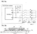
- FIG. 6 is a circuit block diagram showing a second exemplary embodiment of the vehicle headlight system shown in FIG. 3 .
- the second embodiment of the vehicle headlight system 1 can include: a control circuit 35A of a controller 30A outputting a control signal S1 to control whether a light source 10A emits the laser beam 10LB or not, and configured to input a threshold signal S5 output from the light source 10A via a signal line L2; the driving circuit 40 receiving the control signal S1 from the control circuit 35A, and driving the light source 10A of the lighting unit 20A in accordance with the control signal S1; the acceleration sensor 50 of the lighting unit 20A outputting the acceleration signal S2: the integrating circuit 60 removing noises included in the acceleration signal S2, and output said normal acceleration signal S21 substantially not including the noises to the control circuit 35A.
- the control circuit 35A can output the request signal S3 to the acceleration sensor 50, and also can input the response signal S4 including the acceleration ration output from the acceleration sensor 50 in response of the request signal S3.
- the control circuit 35A may not receive the normal response signal S4. Therefore, the second embodiment of the vehicle headlight system 1 can also enable the controller 30A to watch the acceleration ration output from the acceleration sensor 50, and therefore can immediately turn off the light source 10A with the object of protecting human eyes from a laser beam when the lighting unit 20A received the shocks in common with the first embodiment.
- the second embodiment of the headlight system can be a substantially structure as the first embodiment shown in FIG. 1 .
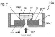
- the light source 10A of the second embodiment may differ from the light source 10 included in the lighting unit 20 of the first embodiment of the headlight system 1. Accordingly, an exemplary light source used for the second embodiment of the vehicle headlight system 1 will now be described in detail with reference to FIG. 7 to FIG. 10 in addition to FIG. 2 .
- the lighting source 10A having a light-emitting surface 10ALS can include: the laser light-emitting device 11 emitting the laser beam; the optical lens 12 located adjacent the laser light-emitting device 11, and focusing the laser beam; the first tubular holder 13 attaching the laser light-emitting device 11 and the optical lens 12 as described above in FIG.
- the wavelength converting material 145 configured to emit the laser beam 14LB having the desirable color tone from the light-emitting surface 10ALS by wavelength-converting the laser beam; a diffusing plate 147 disposed underneath the wavelength converting material 145; a mounting board 142A having a board opening 142AP including a circuit pattern 16 on a top surface 142AT; and a conductive layer 18 disposed underneath the diffusing plate 147, wherein the mounting board 142A attaching the wavelength converting material 145, which is located on the diffusing plate 147 including the conductive layer 18, via bumps 15, which is located between the conductive layer 18 and the circuit pattern 16 of the mounting board 142A, as shown in FIG. 7 , which is a schematic side cross-sectional view depicting an exemplary wavelength converting portion of the light source 10A included in the second embodiment of the vehicle headlight system.
- the lighting source 10A can also include: the reflective material 146 attaching the wavelength converting material 145 disposed on the diffusing plate 147 along with the mounting board 142A, and configured to efficiently emit the laser beam 14LB from the light-emitting surface 10ALS; the second tubular holder 141 having the holder open 141P attaching the wavelength converting material 145 via the mounting board 142A, the diffusing plate 147 and the reflective material 146, and attached to the first tubular holder 13; and wherein the laser beam emitted from the leaser light-emitting device 11 is emitted toward the reflector 21 via the holder opening 141P and the board opening 142AP from the light-emitting surface 10ALS in common with a structure shown in FIG. 1 and FIG. 2 .
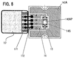
- the wavelength converting portion will now be described in more detail with reference to FIG. 8 , which is a schematic enlarged top view depicting the wavelength converting portion of the light source 10A included in the second embodiment.
- the wavelength converting portion can include: the mounting board 142A having the board opening 142A that passes through the laser beam, including a material having a high thermal conductivity such as aluminum nitride (Al N), and forming the circuit pattern 16 thereon; and a rigid terminal 171 of a flexible circuit board 17 electrically connected to the circuit pattern 16 of the mounting board 14A via a connecting wire 172, and connecting the control circuit 35A of the controller 30A via the signal line L2 as described above with reference with FIG. 6 .
- Al N aluminum nitride
- the wavelength converting portion can also include the bumps 15 electrically and mechanically connecting between the wavelength converting material 145 and mounting board 142A, and the connecting state between the wavelength converting material 145 and the mounting board 142A can be watched by the controller 30A.
- FIG. 9 is a schematic side view depicting the light source including the wavelength converting portion in the second embodiment of the headlight system to show an extending state of the flexible circuit board 17 from the wavelength converting portion in an outward direction of the light source 10A.
- the wavelength converting material 145 can dispose the diffusing plate 147, which is located between the wavelength converting material 145 and the conductive layer 18 so that the diffusing layer 147 can be exposed from the conductive layer 18 at a position located over the boarding opening 142AP to receive the laser beam.
- the mounting board 142A having the board opening 142AP can include the circuit pattern 16 on the top surface 142AT thereof, and also can attach the wavelength converting material 145, which is located on the diffusing plate 147 including the conductive layer 18, via the bumps 15 (A, B, C and D), which are located between the conductive layer 18 and the circuit pattern 16 of the mounting board 142A.
- an exemplary equivalence circuit for examining the connecting state between the wavelength converting material 145 and the mounting board 142A can be shown as FIG. 10a .
- the bump C can connect to ground, and each of the bumps A, B and D can connect to terminals T1, T2 and T3 via the flexible circuit board 17, respectively.
- Each of the bumps A, B and D can connect to pull-up resistances R1, R2 and R3, respectively, and therefore each of the terminal T1, T2 and T3 can become a high level when the connecting state broke due to a degradation of the bumps, etc.
- each of the terminal T1, T2 and T3 can keep a low level.
- FIG. 11 is a table showing an exemplary method for revising the threshold according to the connecting state shown in FIG. 10a .
- Option 1 is a case where the connecting state between the wavelength converting material 145 and the mounting board 142A is normal
- Options 2 and 3 is cases where the bump A or D located between the conductive layer 18 and the circuit pattern 16 of the mounting board 142A breaks.
- Option 4 is a case where the bumps A and D located between the conductive layer 18 and the circuit pattern 16 of the mounting board 142A break
- each of Options 5 and 6 is a case where the bumps C and B located in an inward direction of the bumps 15, which are located between the conductive layer 18 and the circuit pattern 16 of the mounting board 142A break, respectively.
- the threshold can be set up at a default (initial value) in Option 1 because the connecting state is normal.
- the threshold can be set up at a first decreasing value, which is smaller than the initial value because the bump A or D breaks.
- the threshold can be set up at a second decreasing value, which is smaller than the first decreasing value because the bumps A and D break in Option 4.
- the light source 10A can turn off in spite of the connecting state of the bumps A and/or D located in an outward direction of the bumps 15 because the laser beam may become easy to leak from the board opening 142AP of the mounting board 142A.
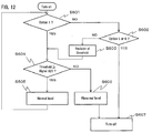
- the controller 30A can watching the above-described connecting state using the signal S5 output from the light source 10A (Step S601).
- Step S601 NO
- Step S602 YES
- the controller 30A can turn off the light source 10A (Step S607).
- the vehicle headlight system of this invention can turn off the light source 10A by anticipating a degradation of the light source 10A, which cannot be accomplished by the above-described conventional light source and the conventional headlight system.
- Step S602 When the connection state is neither Option 5 nor Option 6 (Step S602: No), the controller 30A can revise the threshold from the initial value to either the first decreasing value or the second decreasing value in accordance with the above-described table (Step S603). Then the controller can compare the threshold with the normal acceleration rate S21 output from the integrating circuit 60 (Step S604). When the threshold is more than the normal acceleration rate S21 (Step S604: YES), the controller 30A can determine that the normal acceleration rate S21 is within the normal level, and also can return to Step S601 while turning on the light source 10A. When the threshold is not more than the normal acceleration rate S21 (Step S604: NO), the controller 30A can determine that the normal acceleration rate S21 is an abnormal level (Step S606), and also can turn off the light source 10A (Step S607).
- the controller 30A can examine the connecting state between the wavelength converting material and the mounting board, and also can control to turn off the laser light-emitting device 11 when the threshold is less than the value of the acceleration signal, which is caused by shocks.
- the presently invention can provide vehicle headlight systems using the lighting system, which can turn off the laser light-emitting device 11 by anticipating a degradation of the laser light source.
- the lighting system of this invent can be structured by using necessary elements in accordance with usages.
- the lighting system can various color lights including white color light, which mixes the wavelength-converted light by the wavelength converting material using a part of the laser beam emitted from the laser light-emitting device 11 as an exciting light with another of the direct laser beam. Therefore, the invention can provide lighting systems including an eye-safe function, which can emit lights having various color tones including a substantially white color light, and which can be used as a light source for various lighting units such as vehicle lamps, general lighting, a stage lighting, lighting for show windows, etc.
- FIG. 13 shows the third embodiment of the headlight system using the second embodiment of the headlight system 1 shown in FIG. 6 .
- the third embodiment of the headlight system using the first embodiment of the headlight system shown in FIG. 3 can also be employ as the third embodiment, although a figure for the third embodiment using the first embodiment is abbreviated. Accordingly, the interface circuit 80 and elements associated with the interface circuit 80 will now be described.
- the interface circuit 80 can input light source data 80S such as Option 1 to Option 6, turning-on/off data of the light source 10 (and/or 10A) and the like from a control circuit 35B. For example, when the connection state is either Option 5 or Option 6, the interface circuit 80 can output warning data 90S to a warning circuit 90. The warning circuit 90 can light a warning signal in accordance with the warning data 90S, and therefore can inform drivers of the subject vehicle about the connecting state. Additionally, when a controller 30B turns off the light source 10A due to the above-described big shocks, the interface circuit 80 can output emergency data 85S to a vehicle network circuit 85. The vehicle network circuit 85 can light a hazard lamp and the like, and therefore can inform other drivers about a break of the subject vehicle.
- the vehicle network circuit 85 can light a hazard lamp and the like, and therefore can inform other drivers about a break of the subject vehicle.
- the lighting unit 20 shown in FIG. 1 can be used for a right lamp unit and a left lamp unit attached to each of a right front and a left front of the subject vehicle incorporating the vehicle headlight system 1, respectively.
- the right lamp unit of the lighting unit 20 is substantially same as the left lamp unit. Accordingly, only the lighting unit 20 is described above, and descriptions of the right and the left lamp units are abbreviated above.
- the controller while the controller always watch the degradation of the connecting state between the wavelength converting material and the mounting board, and also can control to turn off the laser light-emitting device when a variable threshold is less than the value of the acceleration signal, which is caused by shocks.
- the presently invention can provide vehicle headlight systems using the lighting system, which can turn off the laser light-emitting device by anticipating the degradation of the laser light source
Landscapes
- Engineering & Computer Science (AREA)
- General Engineering & Computer Science (AREA)
- Physics & Mathematics (AREA)
- Mechanical Engineering (AREA)
- Optics & Photonics (AREA)
- Condensed Matter Physics & Semiconductors (AREA)
- General Physics & Mathematics (AREA)
- Electromagnetism (AREA)
- Lighting Device Outwards From Vehicle And Optical Signal (AREA)
- Semiconductor Lasers (AREA)
Applications Claiming Priority (1)
| Application Number | Priority Date | Filing Date | Title |
|---|---|---|---|
| JP2015165165A JP2017043138A (ja) | 2015-08-24 | 2015-08-24 | 照明装置、照明システム、及び車両用灯具 |
Publications (2)
| Publication Number | Publication Date |
|---|---|
| EP3138732A1 true EP3138732A1 (fr) | 2017-03-08 |
| EP3138732B1 EP3138732B1 (fr) | 2021-06-16 |
Family
ID=57205987
Family Applications (1)
| Application Number | Title | Priority Date | Filing Date |
|---|---|---|---|
| EP16185484.9A Active EP3138732B1 (fr) | 2015-08-24 | 2016-08-24 | Système d'éclairage et système de phares de véhicule utilisant celui-ci |
Country Status (2)
| Country | Link |
|---|---|
| EP (1) | EP3138732B1 (fr) |
| JP (1) | JP2017043138A (fr) |
Cited By (3)
| Publication number | Priority date | Publication date | Assignee | Title |
|---|---|---|---|---|
| US10317031B2 (en) | 2015-04-15 | 2019-06-11 | Koito Manufacturing Co., Ltd. | Vehicle lamp |
| EP3466755A3 (fr) * | 2017-08-16 | 2019-08-21 | LG Electronics Inc. | Phare de véhicule et véhicule le comprenant |
| US11631965B2 (en) | 2020-04-06 | 2023-04-18 | Nichia Corporation | Light emitting device and optical part |
Families Citing this family (2)
| Publication number | Priority date | Publication date | Assignee | Title |
|---|---|---|---|---|
| JP7114906B2 (ja) * | 2018-01-17 | 2022-08-09 | トヨタ自動車株式会社 | 車両用表示装置 |
| JP7132468B2 (ja) * | 2018-06-22 | 2022-09-07 | スタンレー電気株式会社 | 光源装置、車両用ヘッドライト |
Citations (5)
| Publication number | Priority date | Publication date | Assignee | Title |
|---|---|---|---|---|
| US20090257240A1 (en) * | 2008-02-22 | 2009-10-15 | Teruo Koike | Vehicle lamp |
| WO2012124607A1 (fr) * | 2011-03-15 | 2012-09-20 | シャープ株式会社 | Dispositif d'éclairage, phare et véhicule |
| DE102012220481A1 (de) * | 2012-11-09 | 2014-05-15 | Automotive Lighting Reutlingen Gmbh | Lichtmodul |
| JP2014165450A (ja) | 2013-02-27 | 2014-09-08 | Stanley Electric Co Ltd | 半導体発光装置 |
| US20140334167A1 (en) * | 2011-12-29 | 2014-11-13 | Zizala Lichtsysteme Gmbh | Safety device for headlights with laser light sources and method for shutting down laser light sources in case of safety-critical conditions |
Family Cites Families (3)
| Publication number | Priority date | Publication date | Assignee | Title |
|---|---|---|---|---|
| JPS57130837A (en) * | 1981-02-05 | 1982-08-13 | Honda Motor Co Ltd | Automatic winker cancelling system of vehicle |
| JP5523806B2 (ja) * | 2009-12-08 | 2014-06-18 | 株式会社小糸製作所 | 車両用ランプの光照射制御システム |
| JP2013137275A (ja) * | 2011-12-28 | 2013-07-11 | Sinfonia Technology Co Ltd | センサ動作検出装置、センサ動作検出システム及びセンサ動作検出方法 |
-
2015
- 2015-08-24 JP JP2015165165A patent/JP2017043138A/ja active Pending
-
2016
- 2016-08-24 EP EP16185484.9A patent/EP3138732B1/fr active Active
Patent Citations (6)
| Publication number | Priority date | Publication date | Assignee | Title |
|---|---|---|---|---|
| US20090257240A1 (en) * | 2008-02-22 | 2009-10-15 | Teruo Koike | Vehicle lamp |
| WO2012124607A1 (fr) * | 2011-03-15 | 2012-09-20 | シャープ株式会社 | Dispositif d'éclairage, phare et véhicule |
| US20140334167A1 (en) * | 2011-12-29 | 2014-11-13 | Zizala Lichtsysteme Gmbh | Safety device for headlights with laser light sources and method for shutting down laser light sources in case of safety-critical conditions |
| JP2015506301A (ja) | 2011-12-29 | 2015-03-02 | ツィツァラ リヒトシステメ ゲーエムベーハー | レーザー光源を備えるヘッドランプ用安全装置及び安全に関わる危険な状況でのレーザー光源のカットオフ方法 |
| DE102012220481A1 (de) * | 2012-11-09 | 2014-05-15 | Automotive Lighting Reutlingen Gmbh | Lichtmodul |
| JP2014165450A (ja) | 2013-02-27 | 2014-09-08 | Stanley Electric Co Ltd | 半導体発光装置 |
Cited By (3)
| Publication number | Priority date | Publication date | Assignee | Title |
|---|---|---|---|---|
| US10317031B2 (en) | 2015-04-15 | 2019-06-11 | Koito Manufacturing Co., Ltd. | Vehicle lamp |
| EP3466755A3 (fr) * | 2017-08-16 | 2019-08-21 | LG Electronics Inc. | Phare de véhicule et véhicule le comprenant |
| US11631965B2 (en) | 2020-04-06 | 2023-04-18 | Nichia Corporation | Light emitting device and optical part |
Also Published As
| Publication number | Publication date |
|---|---|
| EP3138732B1 (fr) | 2021-06-16 |
| JP2017043138A (ja) | 2017-03-02 |
Similar Documents
| Publication | Publication Date | Title |
|---|---|---|
| EP3138732B1 (fr) | Système d'éclairage et système de phares de véhicule utilisant celui-ci | |
| US10391936B2 (en) | Vehicular lighting device | |
| US10174880B2 (en) | Area monitoring sensor | |
| JP6327535B2 (ja) | レーザー光源を備えるヘッドランプ用安全装置及び安全に関わる危険な状況でのレーザー光源のカットオフ方法 | |
| US9214783B2 (en) | Light emitting device, lighting system, headlight, and vehicle | |
| US9335619B2 (en) | Luminescent light emitting device having luminescent material plate that is caused to be luminous by excitation light source and projector including same luminescent light emitting device | |
| US9371037B2 (en) | Lighting device of a motor vehicle | |
| US8740427B2 (en) | Optimal light coupling for rear view devices | |
| US20180375001A1 (en) | Light source device and projection device | |
| JP6672745B2 (ja) | 光モジュール | |
| CN109073169B (zh) | 基于激光的光源 | |
| CN108303835B (zh) | 结构光投射器及其控制方法、深度相机和电子装置 | |
| WO2018156412A1 (fr) | Boîtier d'illuminateur vcsel sans danger pour l'œil | |
| WO2014087564A1 (fr) | Dispositif d'affichage | |
| EP3936755A1 (fr) | Module lumineux et terminal mobile | |
| WO2014045751A1 (fr) | Appareil d'affichage | |
| EP3200562A1 (fr) | Dispositif d'éclairage de véhicule et phare de véhicule | |
| US10511136B2 (en) | Light module comprising a laser element | |
| JP2015103638A (ja) | 発光装置および画像表示装置 | |
| KR20160012468A (ko) | 차량용 램프의 진단장치 및 진단방법 | |
| JP4611721B2 (ja) | 発光デバイス及び車両用灯具 | |
| JP2017056762A (ja) | 車両用前照灯システム | |
| WO2021035136A1 (fr) | Circuit électrique à travers un élément optique pour détecter des dégâts | |
| US20180270937A1 (en) | Method for operating a first and a second light-emitting unit of a motor vehicle, and circuit arrangement | |
| KR20210043763A (ko) | 눈 보호 기능을 제공하는 빔프로젝터모듈 |
Legal Events
| Date | Code | Title | Description |
|---|---|---|---|
| PUAI | Public reference made under article 153(3) epc to a published international application that has entered the european phase |
Free format text: ORIGINAL CODE: 0009012 |
|
| STAA | Information on the status of an ep patent application or granted ep patent |
Free format text: STATUS: THE APPLICATION HAS BEEN PUBLISHED |
|
| AK | Designated contracting states |
Kind code of ref document: A1 Designated state(s): AL AT BE BG CH CY CZ DE DK EE ES FI FR GB GR HR HU IE IS IT LI LT LU LV MC MK MT NL NO PL PT RO RS SE SI SK SM TR |
|
| AX | Request for extension of the european patent |
Extension state: BA ME |
|
| STAA | Information on the status of an ep patent application or granted ep patent |
Free format text: STATUS: REQUEST FOR EXAMINATION WAS MADE |
|
| 17P | Request for examination filed |
Effective date: 20170908 |
|
| RBV | Designated contracting states (corrected) |
Designated state(s): AL AT BE BG CH CY CZ DE DK EE ES FI FR GB GR HR HU IE IS IT LI LT LU LV MC MK MT NL NO PL PT RO RS SE SI SK SM TR |
|
| STAA | Information on the status of an ep patent application or granted ep patent |
Free format text: STATUS: EXAMINATION IS IN PROGRESS |
|
| 17Q | First examination report despatched |
Effective date: 20190319 |
|
| STAA | Information on the status of an ep patent application or granted ep patent |
Free format text: STATUS: EXAMINATION IS IN PROGRESS |
|
| GRAP | Despatch of communication of intention to grant a patent |
Free format text: ORIGINAL CODE: EPIDOSNIGR1 |
|
| STAA | Information on the status of an ep patent application or granted ep patent |
Free format text: STATUS: GRANT OF PATENT IS INTENDED |
|
| RIC1 | Information provided on ipc code assigned before grant |
Ipc: H01S 5/068 20060101ALN20210120BHEP Ipc: B60Q 1/00 20060101ALN20210120BHEP Ipc: B60Q 1/04 20060101ALN20210120BHEP Ipc: H01S 5/06 20060101ALI20210120BHEP Ipc: B60Q 11/00 20060101ALI20210120BHEP Ipc: F21S 41/176 20180101ALI20210120BHEP Ipc: F21S 41/16 20180101ALI20210120BHEP Ipc: F21S 45/70 20180101ALI20210120BHEP Ipc: B60Q 1/08 20060101AFI20210120BHEP Ipc: B60Q 1/14 20060101ALI20210120BHEP |
|
| INTG | Intention to grant announced |
Effective date: 20210212 |
|
| RAP1 | Party data changed (applicant data changed or rights of an application transferred) |
Owner name: STANLEY ELECTRIC CO., LTD. |
|
| GRAS | Grant fee paid |
Free format text: ORIGINAL CODE: EPIDOSNIGR3 |
|
| GRAA | (expected) grant |
Free format text: ORIGINAL CODE: 0009210 |
|
| STAA | Information on the status of an ep patent application or granted ep patent |
Free format text: STATUS: THE PATENT HAS BEEN GRANTED |
|
| AK | Designated contracting states |
Kind code of ref document: B1 Designated state(s): AL AT BE BG CH CY CZ DE DK EE ES FI FR GB GR HR HU IE IS IT LI LT LU LV MC MK MT NL NO PL PT RO RS SE SI SK SM TR |
|
| REG | Reference to a national code |
Ref country code: GB Ref legal event code: FG4D |
|
| REG | Reference to a national code |
Ref country code: CH Ref legal event code: EP |
|
| REG | Reference to a national code |
Ref country code: DE Ref legal event code: R096 Ref document number: 602016059304 Country of ref document: DE |
|
| REG | Reference to a national code |
Ref country code: AT Ref legal event code: REF Ref document number: 1402072 Country of ref document: AT Kind code of ref document: T Effective date: 20210715 |
|
| REG | Reference to a national code |
Ref country code: IE Ref legal event code: FG4D |
|
| REG | Reference to a national code |
Ref country code: LT Ref legal event code: MG9D |
|
| PG25 | Lapsed in a contracting state [announced via postgrant information from national office to epo] |
Ref country code: FI Free format text: LAPSE BECAUSE OF FAILURE TO SUBMIT A TRANSLATION OF THE DESCRIPTION OR TO PAY THE FEE WITHIN THE PRESCRIBED TIME-LIMIT Effective date: 20210616 Ref country code: LT Free format text: LAPSE BECAUSE OF FAILURE TO SUBMIT A TRANSLATION OF THE DESCRIPTION OR TO PAY THE FEE WITHIN THE PRESCRIBED TIME-LIMIT Effective date: 20210616 Ref country code: BG Free format text: LAPSE BECAUSE OF FAILURE TO SUBMIT A TRANSLATION OF THE DESCRIPTION OR TO PAY THE FEE WITHIN THE PRESCRIBED TIME-LIMIT Effective date: 20210916 Ref country code: HR Free format text: LAPSE BECAUSE OF FAILURE TO SUBMIT A TRANSLATION OF THE DESCRIPTION OR TO PAY THE FEE WITHIN THE PRESCRIBED TIME-LIMIT Effective date: 20210616 |
|
| REG | Reference to a national code |
Ref country code: AT Ref legal event code: MK05 Ref document number: 1402072 Country of ref document: AT Kind code of ref document: T Effective date: 20210616 |
|
| REG | Reference to a national code |
Ref country code: NL Ref legal event code: MP Effective date: 20210616 |
|
| PG25 | Lapsed in a contracting state [announced via postgrant information from national office to epo] |
Ref country code: NO Free format text: LAPSE BECAUSE OF FAILURE TO SUBMIT A TRANSLATION OF THE DESCRIPTION OR TO PAY THE FEE WITHIN THE PRESCRIBED TIME-LIMIT Effective date: 20210916 Ref country code: SE Free format text: LAPSE BECAUSE OF FAILURE TO SUBMIT A TRANSLATION OF THE DESCRIPTION OR TO PAY THE FEE WITHIN THE PRESCRIBED TIME-LIMIT Effective date: 20210616 Ref country code: RS Free format text: LAPSE BECAUSE OF FAILURE TO SUBMIT A TRANSLATION OF THE DESCRIPTION OR TO PAY THE FEE WITHIN THE PRESCRIBED TIME-LIMIT Effective date: 20210616 Ref country code: GR Free format text: LAPSE BECAUSE OF FAILURE TO SUBMIT A TRANSLATION OF THE DESCRIPTION OR TO PAY THE FEE WITHIN THE PRESCRIBED TIME-LIMIT Effective date: 20210917 Ref country code: LV Free format text: LAPSE BECAUSE OF FAILURE TO SUBMIT A TRANSLATION OF THE DESCRIPTION OR TO PAY THE FEE WITHIN THE PRESCRIBED TIME-LIMIT Effective date: 20210616 |
|
| PG25 | Lapsed in a contracting state [announced via postgrant information from national office to epo] |
Ref country code: AT Free format text: LAPSE BECAUSE OF FAILURE TO SUBMIT A TRANSLATION OF THE DESCRIPTION OR TO PAY THE FEE WITHIN THE PRESCRIBED TIME-LIMIT Effective date: 20210616 Ref country code: PT Free format text: LAPSE BECAUSE OF FAILURE TO SUBMIT A TRANSLATION OF THE DESCRIPTION OR TO PAY THE FEE WITHIN THE PRESCRIBED TIME-LIMIT Effective date: 20211018 Ref country code: RO Free format text: LAPSE BECAUSE OF FAILURE TO SUBMIT A TRANSLATION OF THE DESCRIPTION OR TO PAY THE FEE WITHIN THE PRESCRIBED TIME-LIMIT Effective date: 20210616 Ref country code: NL Free format text: LAPSE BECAUSE OF FAILURE TO SUBMIT A TRANSLATION OF THE DESCRIPTION OR TO PAY THE FEE WITHIN THE PRESCRIBED TIME-LIMIT Effective date: 20210616 Ref country code: ES Free format text: LAPSE BECAUSE OF FAILURE TO SUBMIT A TRANSLATION OF THE DESCRIPTION OR TO PAY THE FEE WITHIN THE PRESCRIBED TIME-LIMIT Effective date: 20210616 Ref country code: SK Free format text: LAPSE BECAUSE OF FAILURE TO SUBMIT A TRANSLATION OF THE DESCRIPTION OR TO PAY THE FEE WITHIN THE PRESCRIBED TIME-LIMIT Effective date: 20210616 Ref country code: SM Free format text: LAPSE BECAUSE OF FAILURE TO SUBMIT A TRANSLATION OF THE DESCRIPTION OR TO PAY THE FEE WITHIN THE PRESCRIBED TIME-LIMIT Effective date: 20210616 Ref country code: CZ Free format text: LAPSE BECAUSE OF FAILURE TO SUBMIT A TRANSLATION OF THE DESCRIPTION OR TO PAY THE FEE WITHIN THE PRESCRIBED TIME-LIMIT Effective date: 20210616 Ref country code: EE Free format text: LAPSE BECAUSE OF FAILURE TO SUBMIT A TRANSLATION OF THE DESCRIPTION OR TO PAY THE FEE WITHIN THE PRESCRIBED TIME-LIMIT Effective date: 20210616 |
|
| PG25 | Lapsed in a contracting state [announced via postgrant information from national office to epo] |
Ref country code: PL Free format text: LAPSE BECAUSE OF FAILURE TO SUBMIT A TRANSLATION OF THE DESCRIPTION OR TO PAY THE FEE WITHIN THE PRESCRIBED TIME-LIMIT Effective date: 20210616 |
|
| REG | Reference to a national code |
Ref country code: DE Ref legal event code: R097 Ref document number: 602016059304 Country of ref document: DE |
|
| REG | Reference to a national code |
Ref country code: CH Ref legal event code: PL |
|
| PG25 | Lapsed in a contracting state [announced via postgrant information from national office to epo] |
Ref country code: MC Free format text: LAPSE BECAUSE OF FAILURE TO SUBMIT A TRANSLATION OF THE DESCRIPTION OR TO PAY THE FEE WITHIN THE PRESCRIBED TIME-LIMIT Effective date: 20210616 |
|
| PLBE | No opposition filed within time limit |
Free format text: ORIGINAL CODE: 0009261 |
|
| REG | Reference to a national code |
Ref country code: BE Ref legal event code: MM Effective date: 20210831 |
|
| STAA | Information on the status of an ep patent application or granted ep patent |
Free format text: STATUS: NO OPPOSITION FILED WITHIN TIME LIMIT |
|
| PG25 | Lapsed in a contracting state [announced via postgrant information from national office to epo] |
Ref country code: LI Free format text: LAPSE BECAUSE OF NON-PAYMENT OF DUE FEES Effective date: 20210831 Ref country code: DK Free format text: LAPSE BECAUSE OF FAILURE TO SUBMIT A TRANSLATION OF THE DESCRIPTION OR TO PAY THE FEE WITHIN THE PRESCRIBED TIME-LIMIT Effective date: 20210616 Ref country code: CH Free format text: LAPSE BECAUSE OF NON-PAYMENT OF DUE FEES Effective date: 20210831 |
|
| 26N | No opposition filed |
Effective date: 20220317 |
|
| GBPC | Gb: european patent ceased through non-payment of renewal fee |
Effective date: 20210916 |
|
| PG25 | Lapsed in a contracting state [announced via postgrant information from national office to epo] |
Ref country code: LU Free format text: LAPSE BECAUSE OF NON-PAYMENT OF DUE FEES Effective date: 20210824 Ref country code: AL Free format text: LAPSE BECAUSE OF FAILURE TO SUBMIT A TRANSLATION OF THE DESCRIPTION OR TO PAY THE FEE WITHIN THE PRESCRIBED TIME-LIMIT Effective date: 20210616 |
|
| PG25 | Lapsed in a contracting state [announced via postgrant information from national office to epo] |
Ref country code: IT Free format text: LAPSE BECAUSE OF FAILURE TO SUBMIT A TRANSLATION OF THE DESCRIPTION OR TO PAY THE FEE WITHIN THE PRESCRIBED TIME-LIMIT Effective date: 20210616 Ref country code: IE Free format text: LAPSE BECAUSE OF NON-PAYMENT OF DUE FEES Effective date: 20210824 Ref country code: GB Free format text: LAPSE BECAUSE OF NON-PAYMENT OF DUE FEES Effective date: 20210916 Ref country code: FR Free format text: LAPSE BECAUSE OF NON-PAYMENT OF DUE FEES Effective date: 20210831 Ref country code: BE Free format text: LAPSE BECAUSE OF NON-PAYMENT OF DUE FEES Effective date: 20210831 |
|
| PG25 | Lapsed in a contracting state [announced via postgrant information from national office to epo] |
Ref country code: HU Free format text: LAPSE BECAUSE OF FAILURE TO SUBMIT A TRANSLATION OF THE DESCRIPTION OR TO PAY THE FEE WITHIN THE PRESCRIBED TIME-LIMIT; INVALID AB INITIO Effective date: 20160824 |
|
| PG25 | Lapsed in a contracting state [announced via postgrant information from national office to epo] |
Ref country code: CY Free format text: LAPSE BECAUSE OF FAILURE TO SUBMIT A TRANSLATION OF THE DESCRIPTION OR TO PAY THE FEE WITHIN THE PRESCRIBED TIME-LIMIT Effective date: 20210616 |
|
| PGFP | Annual fee paid to national office [announced via postgrant information from national office to epo] |
Ref country code: DE Payment date: 20230627 Year of fee payment: 8 |
|
| PG25 | Lapsed in a contracting state [announced via postgrant information from national office to epo] |
Ref country code: MK Free format text: LAPSE BECAUSE OF FAILURE TO SUBMIT A TRANSLATION OF THE DESCRIPTION OR TO PAY THE FEE WITHIN THE PRESCRIBED TIME-LIMIT Effective date: 20210616 |