EP3138718A1 - Integrated steering drive axle for vehicle and electric vehicle - Google Patents
Integrated steering drive axle for vehicle and electric vehicle Download PDFInfo
- Publication number
- EP3138718A1 EP3138718A1 EP15786439.8A EP15786439A EP3138718A1 EP 3138718 A1 EP3138718 A1 EP 3138718A1 EP 15786439 A EP15786439 A EP 15786439A EP 3138718 A1 EP3138718 A1 EP 3138718A1
- Authority
- EP
- European Patent Office
- Prior art keywords
- drive
- electric motor
- axle
- vehicle
- corresponding wheel
- Prior art date
- Legal status (The legal status is an assumption and is not a legal conclusion. Google has not performed a legal analysis and makes no representation as to the accuracy of the status listed.)
- Granted
Links
Images

Classifications
-
- B—PERFORMING OPERATIONS; TRANSPORTING
- B60—VEHICLES IN GENERAL
- B60K—ARRANGEMENT OR MOUNTING OF PROPULSION UNITS OR OF TRANSMISSIONS IN VEHICLES; ARRANGEMENT OR MOUNTING OF PLURAL DIVERSE PRIME-MOVERS IN VEHICLES; AUXILIARY DRIVES FOR VEHICLES; INSTRUMENTATION OR DASHBOARDS FOR VEHICLES; ARRANGEMENTS IN CONNECTION WITH COOLING, AIR INTAKE, GAS EXHAUST OR FUEL SUPPLY OF PROPULSION UNITS IN VEHICLES
- B60K17/00—Arrangement or mounting of transmissions in vehicles
- B60K17/04—Arrangement or mounting of transmissions in vehicles characterised by arrangement, location or kind of gearing
- B60K17/14—Arrangement or mounting of transmissions in vehicles characterised by arrangement, location or kind of gearing the motor of fluid or electric gearing being disposed in, or adjacent to, traction wheel
-
- B—PERFORMING OPERATIONS; TRANSPORTING
- B60—VEHICLES IN GENERAL
- B60K—ARRANGEMENT OR MOUNTING OF PROPULSION UNITS OR OF TRANSMISSIONS IN VEHICLES; ARRANGEMENT OR MOUNTING OF PLURAL DIVERSE PRIME-MOVERS IN VEHICLES; AUXILIARY DRIVES FOR VEHICLES; INSTRUMENTATION OR DASHBOARDS FOR VEHICLES; ARRANGEMENTS IN CONNECTION WITH COOLING, AIR INTAKE, GAS EXHAUST OR FUEL SUPPLY OF PROPULSION UNITS IN VEHICLES
- B60K7/00—Disposition of motor in, or adjacent to, traction wheel
- B60K7/0007—Disposition of motor in, or adjacent to, traction wheel the motor being electric
-
- B—PERFORMING OPERATIONS; TRANSPORTING
- B60—VEHICLES IN GENERAL
- B60K—ARRANGEMENT OR MOUNTING OF PROPULSION UNITS OR OF TRANSMISSIONS IN VEHICLES; ARRANGEMENT OR MOUNTING OF PLURAL DIVERSE PRIME-MOVERS IN VEHICLES; AUXILIARY DRIVES FOR VEHICLES; INSTRUMENTATION OR DASHBOARDS FOR VEHICLES; ARRANGEMENTS IN CONNECTION WITH COOLING, AIR INTAKE, GAS EXHAUST OR FUEL SUPPLY OF PROPULSION UNITS IN VEHICLES
- B60K1/00—Arrangement or mounting of electrical propulsion units
- B60K1/02—Arrangement or mounting of electrical propulsion units comprising more than one electric motor
-
- B—PERFORMING OPERATIONS; TRANSPORTING
- B60—VEHICLES IN GENERAL
- B60K—ARRANGEMENT OR MOUNTING OF PROPULSION UNITS OR OF TRANSMISSIONS IN VEHICLES; ARRANGEMENT OR MOUNTING OF PLURAL DIVERSE PRIME-MOVERS IN VEHICLES; AUXILIARY DRIVES FOR VEHICLES; INSTRUMENTATION OR DASHBOARDS FOR VEHICLES; ARRANGEMENTS IN CONNECTION WITH COOLING, AIR INTAKE, GAS EXHAUST OR FUEL SUPPLY OF PROPULSION UNITS IN VEHICLES
- B60K17/00—Arrangement or mounting of transmissions in vehicles
- B60K17/04—Arrangement or mounting of transmissions in vehicles characterised by arrangement, location or kind of gearing
- B60K17/043—Transmission unit disposed in on near the vehicle wheel, or between the differential gear unit and the wheel
-
- B—PERFORMING OPERATIONS; TRANSPORTING
- B60—VEHICLES IN GENERAL
- B60K—ARRANGEMENT OR MOUNTING OF PROPULSION UNITS OR OF TRANSMISSIONS IN VEHICLES; ARRANGEMENT OR MOUNTING OF PLURAL DIVERSE PRIME-MOVERS IN VEHICLES; AUXILIARY DRIVES FOR VEHICLES; INSTRUMENTATION OR DASHBOARDS FOR VEHICLES; ARRANGEMENTS IN CONNECTION WITH COOLING, AIR INTAKE, GAS EXHAUST OR FUEL SUPPLY OF PROPULSION UNITS IN VEHICLES
- B60K17/00—Arrangement or mounting of transmissions in vehicles
- B60K17/04—Arrangement or mounting of transmissions in vehicles characterised by arrangement, location or kind of gearing
- B60K17/06—Arrangement or mounting of transmissions in vehicles characterised by arrangement, location or kind of gearing of change-speed gearing
- B60K17/08—Arrangement or mounting of transmissions in vehicles characterised by arrangement, location or kind of gearing of change-speed gearing of mechanical type
-
- B—PERFORMING OPERATIONS; TRANSPORTING
- B60—VEHICLES IN GENERAL
- B60K—ARRANGEMENT OR MOUNTING OF PROPULSION UNITS OR OF TRANSMISSIONS IN VEHICLES; ARRANGEMENT OR MOUNTING OF PLURAL DIVERSE PRIME-MOVERS IN VEHICLES; AUXILIARY DRIVES FOR VEHICLES; INSTRUMENTATION OR DASHBOARDS FOR VEHICLES; ARRANGEMENTS IN CONNECTION WITH COOLING, AIR INTAKE, GAS EXHAUST OR FUEL SUPPLY OF PROPULSION UNITS IN VEHICLES
- B60K17/00—Arrangement or mounting of transmissions in vehicles
- B60K17/30—Arrangement or mounting of transmissions in vehicles the ultimate propulsive elements, e.g. ground wheels, being steerable
-
- B—PERFORMING OPERATIONS; TRANSPORTING
- B60—VEHICLES IN GENERAL
- B60K—ARRANGEMENT OR MOUNTING OF PROPULSION UNITS OR OF TRANSMISSIONS IN VEHICLES; ARRANGEMENT OR MOUNTING OF PLURAL DIVERSE PRIME-MOVERS IN VEHICLES; AUXILIARY DRIVES FOR VEHICLES; INSTRUMENTATION OR DASHBOARDS FOR VEHICLES; ARRANGEMENTS IN CONNECTION WITH COOLING, AIR INTAKE, GAS EXHAUST OR FUEL SUPPLY OF PROPULSION UNITS IN VEHICLES
- B60K17/00—Arrangement or mounting of transmissions in vehicles
- B60K17/30—Arrangement or mounting of transmissions in vehicles the ultimate propulsive elements, e.g. ground wheels, being steerable
- B60K17/306—Arrangement or mounting of transmissions in vehicles the ultimate propulsive elements, e.g. ground wheels, being steerable with a universal joint in the axis of the steering knuckle
-
- Y—GENERAL TAGGING OF NEW TECHNOLOGICAL DEVELOPMENTS; GENERAL TAGGING OF CROSS-SECTIONAL TECHNOLOGIES SPANNING OVER SEVERAL SECTIONS OF THE IPC; TECHNICAL SUBJECTS COVERED BY FORMER USPC CROSS-REFERENCE ART COLLECTIONS [XRACs] AND DIGESTS
- Y02—TECHNOLOGIES OR APPLICATIONS FOR MITIGATION OR ADAPTATION AGAINST CLIMATE CHANGE
- Y02T—CLIMATE CHANGE MITIGATION TECHNOLOGIES RELATED TO TRANSPORTATION
- Y02T10/00—Road transport of goods or passengers
- Y02T10/60—Other road transportation technologies with climate change mitigation effect
- Y02T10/72—Electric energy management in electromobility
Definitions
- the present invention relates to the industry of electric vehicles, and in particular, to an integrated steering drive axle and an electric vehicle.
- An existing electric vehicle typically has two drive axles, and each drive axle is used for driving a pair of wheels located at opposite sides of the vehicle.
- Each drive axle receives a driving force provided by a drive electric motor arranged at the front or the rear of the vehicle. According to the number and the positions of the drive axles driven by the drive electric motor, the electric vehicle may achieve front-wheel drive, rear-wheel drive or four-wheel drive.
- a vehicle with a larger carrying capacity for example, a large or heavy passenger bus or truck
- its chassis is generally provided with more drive axles, for example, four axles, six axles or eight axles.
- the driving structure of such a vehicle is complex, and thus corresponding eight-wheel drive, twelve-wheel drive or sixteen-wheel drive are more difficult to achieve.
- Due to the limitation of the electric energy storage technology of the existing electric vehicle when considering the necessary power demands and the endurance mileage, such a vehicle typically employs a fuel engine as a direct power source, instead of being driven by a drive electric motor as in the electric vehicle.
- Chinese patent application No. 201310467918.2 of the applicant provides a power system for a series hybrid electric vehicle.
- the power system allows the use of alternative fuels with lower energy density instead of using traditional gasoline or diesel, and allows an engine in an auxiliary power unit to work in a working condition area in which both oil consumption and emission are very low, thereby effectively reducing the emission, improving the economic efficiency of the fuels, and compensating for the problem that the energy conversion efficiency of the power system of the series hybrid electric vehicle is relatively low.
- the power system can be flexibly provided with an appropriate number of engines for combined use according to demands.
- electric power sufficient to meet the demands of the vehicle with a larger carrying capacity, for example a truck can be provided by using cheap fuels, thereby providing possibility for an electric driving mode of such a vehicle.
- wheels on opposite sides of one axle are generally driven by one drive electric motor, which is not conducive to the flexibility of the controlling of the electric vehicle.
- Another solution for the existing electric vehicle is to employ an in-wheel motor, but the cost is high, and because of the limitation on the provided power, it is merely applied to vehicles with a small carrying capacity, such as family cars.
- an integrated steering drive axle for a vehicle used for mounting two wheels respectively at corresponding opposite sides thereof and driving the wheels to rotate and turn, and including: an integrally rigid axle beam, which can be arranged to extend between the two wheels along a lateral direction of the vehicle; two motor drive systems mounted at the axle beam, wherein each motor drive system can independently drive a corresponding one of the two wheels to rotate and turn.
- Each motor drive system includes: a first drive electric motor, arranged separately from the corresponding wheel; a first transmission mechanism, arranged between the first drive electric motor and the corresponding wheel and used for transferring the output power of the first drive electric motor to the corresponding wheel to drive the corresponding wheel to rotate; and a second drive electric motor, used for providing steering power necessary for turning or steering the corresponding wheel.
- the first transmission mechanism includes a speed reducer, used for transferring the output power of the first drive electric motor and outputting a reduced rotating speed compared with the rotating speed of a rotating shaft of the first drive electric motor.
- the first drive electric motor is arranged so that a rotation axis of the rotating shaft thereof extends along the lateral direction of the vehicle.
- the first transmission mechanism of the vehicle further includes a half-shaft, used for transferring the output power of the first drive electric motor to the corresponding wheel, wherein the whole or a part of the half-shaft is configured to be capable of swing with the turning of the wheel.
- the half-shaft includes a first part and a second part, which are in transmission connection by a universal joint, wherein the first part is configured to be capable of swing with the turning of the wheel, and the second part is formed by the rotating shaft of the first drive electric motor.
- each motor drive system further includes a second transmission mechanism mounted at the axle beam, and the second transmission mechanism is arranged between the second drive electric motor and the corresponding wheel and is used for transferring the output power of the second drive electric motor to the corresponding wheel to drive the corresponding wheel to turn.
- the axle beam is formed into a form of a hollow axle housing
- the first drive electric motor is arranged in the hollow axle housing; optionally, the second drive electric motor is also arranged in the hollow axle housing; and further optionally, at least a part of the first transmission mechanism is also arranged in the hollow axle housing.
- an electric vehicle including a plurality of axles, wherein at least one of the plurality of axles is the foregoing integrated steering drive axle.
- each one of the plurality of axles adopts the integrated steering drive axle.
- the plurality of axles include at least 3 axles, and optionally, the plurality of axles include at least 4 axles.
- two motor drive systems respectively for independently driving the corresponding wheels at opposite sides are mounted on the integrated steering drive axle and are respectively used for controlling the turning and the rotating of the corresponding wheel, thereby improving the control flexibility of the vehicle and achieving independent driving and independent turning or steering of the wheels.
- the integrated steering drive axle of the present invention is particularly suitable for use in vehicles with a large carrying capacity, for example, large or heavy passenger buses or trucks.
- the integrated steering drive axle is further particularly suitable as a motor drive axle transformed from an existing axle with fuel engine power.
- motor drive systems for driving the corresponding wheels constitute a modular structure together with the axle by a preassembly manner, so as to facilitate and simplify the mounting of the axles of the vehicle.
- Figs. 1 to 5 respectively show schematic structural diagrams of a plurality of embodiments of an integrated steering drive axle 100 according to the present invention.
- the integrated steering drive axle 100 is generally used for mounting two wheels 130 respectively at corresponding opposite sides thereof and driving the wheels 130 to rotate and turn.
- the integrated steering drive axle 100 may include an integrally rigid axle beam 120, and the axle beam 120 may be arranged to extend between the two wheels 130 along the lateral direction of the vehicle.
- Two motor drive systems 110 may be mounted at the axle beam 120, and each motor drive system 110 may independently drive one corresponding wheel 130 of the two wheels 130 to rotate and turn.
- Each motor drive system 110 is arranged adjacent to the corresponding wheel 130 and may include a first drive electric motor 150, a first transmission mechanism 160 and a second drive electric motor 170.
- the first drive electric motor 150 is arranged separately from the corresponding wheel 130, that is to say, no part of the first drive electric motor 150 belongs to the wheel 130, which is apparently different from the in-wheel motor in the prior art, and thus the first drive electric motor 150 may the form of a conventional motor.
- the first transmission mechanism 160 may be arranged between the first drive electric motor 150 and the corresponding wheel 130 and is used for transferring the output power of the first drive electric motor 150 to the corresponding wheel 130 to drive the corresponding wheel 130 to rotate, so as to cause the vehicle to move forward or backward.
- the second drive electric motor 170 may be used for providing steering power necessary for turning or steering the corresponding wheel 130, so as to drive the corresponding wheel 130 to deflect from the travelling direction of the vehicle.
- the two motor drive systems 110 are integrated with a single axle to respectively steer and rotate the two corresponding wheels 130.
- the two motor drive systems 110 can work independently from each other to achieve independent control of the two corresponding wheels 130, so as to allow individually independent rotating and steering of the two wheels 130.
- the first transmission mechanism 160 may further include a speed reducer 163 for transferring the output power of the first drive electric motor 150.
- the speed reducer 163 can achieve a reduced rotating speed compared with the rotating speed of a rotating shaft 151 of the first drive electric motor 150, so as to increase the torque while reducing the rotating speed.
- the first drive electric motor 150 is arranged so that the rotation axis of the rotating shaft 151 thereof extends along the lateral direction of the vehicle, that is, basically parallel to the axle beam 120.
- the torque output direction of the rotating shaft 151 of the first drive electric motor 150 is the same as the torque direction required for driving the corresponding wheel 130 to rotate, so that the power thereof can be transferred to the corresponding wheel 130 by the speed reducer 163 without changing the torque direction of the rotating shaft 151 of the first drive electric motor 150.
- the speed reducer 163 only plays the function of reducing the rotating speed, and this can be simply achieved by a reduction gear set composed of a plurality of parallel gears.
- the first drive electric motor 150 arranged in such manner is beneficial to decreasing the overall lateral size of the integrated steering drive axle 100.
- the rotating shaft 151 of the first drive electric motor 150 is arranged coaxially with a half-shaft 161 that will be described below, and in the embodiment as shown in Fig. 5 , the rotating shaft 151 of the first drive electric motor 150 is arranged to be parallel to, but offset from the half-shaft 161, and the speed reducer 163 therebetween is used for transferring of the torque.
- the first drive electric motor 150 is arranged so that the rotation axis of the rotating shaft 151 thereof extends along the longitudinal direction of the vehicle, and this is similar to the arrangement of a conventional longitudinal transmission shaft in an existing vehicle power train.
- the speed reducer 163 may adopt a structure similar to that of the existing speed reducer, for example, is achieved by conical gear pairs, which are arranged to be vertical to each other. In this way, the speed reducer 163 may directly transfer the torque of the rotating shaft 151 of the first drive electric motor 150, as well changing the direction of the torque.
- the first drive electric motor 150 arranged in such manner is more beneficial to the transformation of the existing axles.
- the first transmission mechanism 160 may further include the half-shaft 161 for transferring the output power of the first drive electric motor 150 to the corresponding wheel 130.
- the half-shaft 161 may have a structure that is basically similar to that of the half-shaft of the existing vehicle, but obviously, in the present invention, as each half-shaft 161 is directly driven by one first drive electric motor 150 arranged in the vicinity, instead of two opposite half-shafts being driven by one transmission shaft as in the prior art. Therefore, in the case that the first drive electric motor 150 is arranged to be closer to the corresponding wheel 130, the length of the half-shaft 161 can be shorter than that of the existing conventional half-shaft.
- the half-shaft 161 is configured to be capable of swing with the turning or steering of the corresponding wheel 130.
- the half-shaft 161 may include a first part and a second part, which are in transmission connection via a universal joint 162 (usually a constant velocity universal joint), and in Figs. 1 to 5 , the first part and the second part are respectively a left segment and a right segment of the half-shaft 161, which are separated by the universal joint 162.
- the first part of the half-shaft 161 is configured to be capable of swing with the steering of the corresponding wheel 130, and the second part of the half-shaft 161 may be held to be only rotatable.
- the rotating shaft 151 of the first drive electric motor 150 is arranged coaxially with the half-shaft 161 that will be described below, and in this case, although not shown in the figures, it is conceivable that the rotating shaft 151 of the first drive electric motor 150 may extend farther towards the universal joint 162, and the rotating shaft 151 of the first drive electric motor 150 may even be directly formed as or used as the second part of the half-shaft 161. In this case, the half-shaft 161 may be deemed as being formed only by the part at the left of the universal joint 162, so the entire half-shaft 161 is configured to be capable of swing with the steering of the corresponding wheel 130.
- the motor drive system 110 may further include a second transmission mechanism 180 mounted at the axle beam 120.
- the second transmission mechanism 180 is arranged between the second drive electric motor 170 and the corresponding wheel 130 and is used for transferring the output power of the second drive electric motor 170 to the corresponding wheel 130, so as to drive a steering knuckle 140 of the corresponding wheel 130 to propel the corresponding wheel 130 to turn.
- the second transmission mechanism 180 may include a steering gear 182 and a steering lever 181.
- the steering gear 182 may convert the rotation of a rotating shaft 171 of the second drive electric motor 170 into linear motion of the steering lever 181, so as to pull a pull rod arm 141 of the steering knuckle 140 at the corresponding wheel 130, to achieve turning or steering of the corresponding wheel 130.
- the rotating shaft 171 of the second drive electric motor 170 extends along a direction that is basically parallel to the axle beam120 or the steering lever 181.
- the rotating shaft 171 of the second drive electric motor 170 extends along a direction that is vertical to the axle beam 120 or the steering lever 181.
- a specific structure of the steering gear 182 may adopt a suitable steering gear structure in the prior art according to the arrangement direction of the second drive electric motor 170. Particularly in the case of Fig. 4 , the steering gear 182 may conveniently adopt a structure of rack-and-pinion steering gear in the prior art. When the output rotating speed of the second drive electric motor 170 needs to be reduced, the steering gear 182 may be additionally further provided with a reduction mechanism, such as a reduction gear set.
- the axle beam 120 can be formed as a hollow axle housing for arranging several components of the integrated steering drive axle 100 therein.
- both of the two motor drive systems 110 are mounted in the axle beam 120 provided with the hollow axle housing.
- the first drive electric motor 150, the first transmission mechanism 160, the second drive electric motor 170 and the second transmission mechanism 180 may be pre-assembled before being mounted in the axle beam 120.
- the first drive electric motor 150 and the first transmission mechanism 160 are mounted in the hollow axle housing as the axle beam.
- the second drive electric motor 170, the steering gear 182 and the like may be mounted on a mounting frame 172 (schematically represented by dotted lines in the figure) that is fixed at the outside of the axle beam 120, and are held by the mounting frame 172.
- the mounting frame 172 may also be formed into a basically enclosed housing shape.
- the specific shape of the hollow axle housing may be designed according to the arrangement positions and the shapes of the components therein, for example, the surface of the axle housing is designed to fit to the overall outlines of all components therein to form a compact axle housing.
- the two motor drive systems 110 may be fixedly mounted at the outside of the solid axle beam 120.
- the components may be conveniently mounted to and held by the mounting frame 172 (schematically represented by dotted lines in the figures) that is fixed at the outside of the axle beam 120.
- the mounting frame 172 may also be formed into a basically enclosed housing shape, in order to enclose the two motor drive systems 110.
- the present invention further provides an electric vehicle including a plurality of axles, wherein at least one of the plurality of axles is the foregoing integrated steering drive axle 100. Further, each one of all axles in the electric vehicle may adopt the integrated steering drive axle 100.
- the integrated steering drive axle 100 of the present invention is particularly suitable for use in vehicles with a large carrying capacity, for example, large or heavy passenger buses or trucks.
- the electric vehicle may have more axles, for example, at least 3 and even at least 4 axles, and each axle may adopt the integrated steering drive axle 100 according to the present invention.
- three axles respectively at the front, middle and rear of the electric vehicle may adopt the integrated steering drive axles 100, and the axle between every two adjacent integrated steering drive axles may adopt other axle structures in the existing vehicle, for example, an axle for mounting follower wheels.
- the integrated steering drive axle 100 in the present invention may be conveniently obtained by transforming the existing integrated steering drive axle driven by a fuel engine. Specific wheel rotating and steering structures may directly adopt the structures in the existing vehicle, and the transmission shaft and the steering motor in the existing vehicle are replaced by the corresponding first drive electric motor 150 and the second drive electric motor 170. In addition, after the corresponding wheel is independently controlled by the first drive electric motor 150 and the second drive electric motor 170, differentials used in the axles in the existing vehicle can be omitted.
Landscapes
- Engineering & Computer Science (AREA)
- Chemical & Material Sciences (AREA)
- Combustion & Propulsion (AREA)
- Transportation (AREA)
- Mechanical Engineering (AREA)
- Arrangement Or Mounting Of Propulsion Units For Vehicles (AREA)
- Power Steering Mechanism (AREA)
- Arrangement Of Transmissions (AREA)
- Motor Power Transmission Devices (AREA)
- Arrangement And Driving Of Transmission Devices (AREA)
- Electric Propulsion And Braking For Vehicles (AREA)
Abstract
Description
- The present invention relates to the industry of electric vehicles, and in particular, to an integrated steering drive axle and an electric vehicle.
- An existing electric vehicle typically has two drive axles, and each drive axle is used for driving a pair of wheels located at opposite sides of the vehicle. Each drive axle receives a driving force provided by a drive electric motor arranged at the front or the rear of the vehicle. According to the number and the positions of the drive axles driven by the drive electric motor, the electric vehicle may achieve front-wheel drive, rear-wheel drive or four-wheel drive.
- For a vehicle with a larger carrying capacity, for example, a large or heavy passenger bus or truck, its chassis is generally provided with more drive axles, for example, four axles, six axles or eight axles. The driving structure of such a vehicle is complex, and thus corresponding eight-wheel drive, twelve-wheel drive or sixteen-wheel drive are more difficult to achieve. Due to the limitation of the electric energy storage technology of the existing electric vehicle, when considering the necessary power demands and the endurance mileage, such a vehicle typically employs a fuel engine as a direct power source, instead of being driven by a drive electric motor as in the electric vehicle.
- Chinese patent application No.
201310467918.2 - For the existing electric vehicle employing the drive electric motor, wheels on opposite sides of one axle are generally driven by one drive electric motor, which is not conducive to the flexibility of the controlling of the electric vehicle. Another solution for the existing electric vehicle is to employ an in-wheel motor, but the cost is high, and because of the limitation on the provided power, it is merely applied to vehicles with a small carrying capacity, such as family cars.
- One object of the present invention is to provide an integrated steering drive axle for a vehicle, which is particularly suitable for vehicles with a large carrying capacity, for example, large or heavy passenger buses or trucks. Another object of the present invention is to provide a modular mounting assembly integrating electric motors for rotating and turning with the axle. A further object of the present invention is to provide an electric vehicle provided with the aforementioned integrated steering drive axle.
- According to one aspect of the present invention, an integrated steering drive axle for a vehicle is provided, used for mounting two wheels respectively at corresponding opposite sides thereof and driving the wheels to rotate and turn, and including: an integrally rigid axle beam, which can be arranged to extend between the two wheels along a lateral direction of the vehicle; two motor drive systems mounted at the axle beam, wherein each motor drive system can independently drive a corresponding one of the two wheels to rotate and turn. Each motor drive system includes: a first drive electric motor, arranged separately from the corresponding wheel; a first transmission mechanism, arranged between the first drive electric motor and the corresponding wheel and used for transferring the output power of the first drive electric motor to the corresponding wheel to drive the corresponding wheel to rotate; and a second drive electric motor, used for providing steering power necessary for turning or steering the corresponding wheel.
- Further, the first transmission mechanism includes a speed reducer, used for transferring the output power of the first drive electric motor and outputting a reduced rotating speed compared with the rotating speed of a rotating shaft of the first drive electric motor.
- Further, the first drive electric motor is arranged so that a rotation axis of the rotating shaft thereof extends along the lateral direction of the vehicle.
- Further, the first transmission mechanism of the vehicle further includes a half-shaft, used for transferring the output power of the first drive electric motor to the corresponding wheel, wherein the whole or a part of the half-shaft is configured to be capable of swing with the turning of the wheel.
- Further, the half-shaft includes a first part and a second part, which are in transmission connection by a universal joint, wherein the first part is configured to be capable of swing with the turning of the wheel, and the second part is formed by the rotating shaft of the first drive electric motor.
- Further, each motor drive system further includes a second transmission mechanism mounted at the axle beam, and the second transmission mechanism is arranged between the second drive electric motor and the corresponding wheel and is used for transferring the output power of the second drive electric motor to the corresponding wheel to drive the corresponding wheel to turn.
- Further, the axle beam is formed into a form of a hollow axle housing,
the first drive electric motor is arranged in the hollow axle housing;
optionally, the second drive electric motor is also arranged in the hollow axle housing; and
further optionally, at least a part of the first transmission mechanism is also arranged in the hollow axle housing. - According to another aspect of the present invention, an electric vehicle is further provided, including a plurality of axles, wherein at least one of the plurality of axles is the foregoing integrated steering drive axle.
- Further, each one of the plurality of axles adopts the integrated steering drive axle. Further, the plurality of axles include at least 3 axles, and optionally, the plurality of axles include at least 4 axles.
- According to the present invention, two motor drive systems respectively for independently driving the corresponding wheels at opposite sides are mounted on the integrated steering drive axle and are respectively used for controlling the turning and the rotating of the corresponding wheel, thereby improving the control flexibility of the vehicle and achieving independent driving and independent turning or steering of the wheels. The integrated steering drive axle of the present invention is particularly suitable for use in vehicles with a large carrying capacity, for example, large or heavy passenger buses or trucks. In some embodiments of the present invention, the integrated steering drive axle is further particularly suitable as a motor drive axle transformed from an existing axle with fuel engine power.
- Further, the motor drive systems for driving the corresponding wheels constitute a modular structure together with the axle by a preassembly manner, so as to facilitate and simplify the mounting of the axles of the vehicle.
- According to the following detailed description of specific embodiments of the present invention in conjunction with the drawings, those skilled in the art will better understand the aforementioned and other objects, advantages and features of the present invention.
- Some specific embodiments of the present invention will be described below in detail in an exemplary, rather than a restrictive manner with reference to the drawings. Identical reference signs in the drawings represent identical or similar components or parts. Those skilled in the art should understand that these drawings are not necessarily drawn to scale. In the drawings:
-
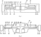
Fig. 1 is a schematic structural diagram of an integrated steering drive axle according to one embodiment of the present invention; -
Fig. 2 is a schematic structural diagram of an integrated steering drive axle according to one embodiment of the present invention, wherein the axle beam is a hollow housing; -
Fig. 3 is a schematic structural diagram of an integrated steering drive axle according to one embodiment of the present invention, wherein only the first drive electric motor and the first transmission system are mounted within the axle beam as a hollow axle housing; -
Fig. 4 is a schematic structural diagram of an integrated steering drive axle according to one embodiment of the present invention, wherein a motor drive system is mounted at a rigid solid axle beam; -
Fig. 5 is a schematic structural diagram in one embodiment of the present invention, in which the torque direction of a rotating shaft of the first drive electric motor is consistent with the rotating direction of a corresponding wheel. -
Figs. 1 to 5 respectively show schematic structural diagrams of a plurality of embodiments of an integratedsteering drive axle 100 according to the present invention. In the present invention, the integratedsteering drive axle 100 is generally used for mounting twowheels 130 respectively at corresponding opposite sides thereof and driving thewheels 130 to rotate and turn. It should be noted that thewheels 130 shown in the drawings are only hub parts thereof. The integratedsteering drive axle 100 may include an integrallyrigid axle beam 120, and theaxle beam 120 may be arranged to extend between the twowheels 130 along the lateral direction of the vehicle. Twomotor drive systems 110 may be mounted at theaxle beam 120, and eachmotor drive system 110 may independently drive onecorresponding wheel 130 of the twowheels 130 to rotate and turn. Eachmotor drive system 110 is arranged adjacent to thecorresponding wheel 130 and may include a first driveelectric motor 150, afirst transmission mechanism 160 and a second driveelectric motor 170. The first driveelectric motor 150 is arranged separately from thecorresponding wheel 130, that is to say, no part of the first driveelectric motor 150 belongs to thewheel 130, which is apparently different from the in-wheel motor in the prior art, and thus the first driveelectric motor 150 may the form of a conventional motor. Thefirst transmission mechanism 160 may be arranged between the first driveelectric motor 150 and thecorresponding wheel 130 and is used for transferring the output power of the first driveelectric motor 150 to thecorresponding wheel 130 to drive thecorresponding wheel 130 to rotate, so as to cause the vehicle to move forward or backward. The second driveelectric motor 170 may be used for providing steering power necessary for turning or steering thecorresponding wheel 130, so as to drive thecorresponding wheel 130 to deflect from the travelling direction of the vehicle. According to the integratedsteering drive axle 100, the twomotor drive systems 110 are integrated with a single axle to respectively steer and rotate the twocorresponding wheels 130. The twomotor drive systems 110 can work independently from each other to achieve independent control of the twocorresponding wheels 130, so as to allow individually independent rotating and steering of the twowheels 130. - The
first transmission mechanism 160 may further include aspeed reducer 163 for transferring the output power of the first driveelectric motor 150. Thespeed reducer 163 can achieve a reduced rotating speed compared with the rotating speed of a rotatingshaft 151 of the first driveelectric motor 150, so as to increase the torque while reducing the rotating speed. - In the embodiments as shown in
Figs. 1 ,4 and 5 , the first driveelectric motor 150 is arranged so that the rotation axis of therotating shaft 151 thereof extends along the lateral direction of the vehicle, that is, basically parallel to theaxle beam 120. In this structure, the torque output direction of the rotatingshaft 151 of the first driveelectric motor 150 is the same as the torque direction required for driving thecorresponding wheel 130 to rotate, so that the power thereof can be transferred to thecorresponding wheel 130 by thespeed reducer 163 without changing the torque direction of therotating shaft 151 of the first driveelectric motor 150. In this way, thespeed reducer 163 only plays the function of reducing the rotating speed, and this can be simply achieved by a reduction gear set composed of a plurality of parallel gears. The first driveelectric motor 150 arranged in such manner is beneficial to decreasing the overall lateral size of the integratedsteering drive axle 100. In the embodiments as shown inFigs. 1 and4 , therotating shaft 151 of the first driveelectric motor 150 is arranged coaxially with a half-shaft 161 that will be described below, and in the embodiment as shown inFig. 5 , therotating shaft 151 of the first driveelectric motor 150 is arranged to be parallel to, but offset from the half-shaft 161, and thespeed reducer 163 therebetween is used for transferring of the torque. - In the embodiments as shown in
Figs. 2 and3 , the first driveelectric motor 150 is arranged so that the rotation axis of therotating shaft 151 thereof extends along the longitudinal direction of the vehicle, and this is similar to the arrangement of a conventional longitudinal transmission shaft in an existing vehicle power train. At this time, thespeed reducer 163 may adopt a structure similar to that of the existing speed reducer, for example, is achieved by conical gear pairs, which are arranged to be vertical to each other. In this way, thespeed reducer 163 may directly transfer the torque of therotating shaft 151 of the first driveelectric motor 150, as well changing the direction of the torque. The first driveelectric motor 150 arranged in such manner is more beneficial to the transformation of the existing axles. - The
first transmission mechanism 160 may further include the half-shaft 161 for transferring the output power of the first driveelectric motor 150 to thecorresponding wheel 130. The half-shaft 161 may have a structure that is basically similar to that of the half-shaft of the existing vehicle, but obviously, in the present invention, as each half-shaft 161 is directly driven by one first driveelectric motor 150 arranged in the vicinity, instead of two opposite half-shafts being driven by one transmission shaft as in the prior art. Therefore, in the case that the first driveelectric motor 150 is arranged to be closer to thecorresponding wheel 130, the length of the half-shaft 161 can be shorter than that of the existing conventional half-shaft. To allow turning or steering of thewheel 130, the whole or a part of the half-shaft 161 is configured to be capable of swing with the turning or steering of thecorresponding wheel 130. The half-shaft 161 may include a first part and a second part, which are in transmission connection via a universal joint 162 (usually a constant velocity universal joint), and inFigs. 1 to 5 , the first part and the second part are respectively a left segment and a right segment of the half-shaft 161, which are separated by theuniversal joint 162. The first part of the half-shaft 161 is configured to be capable of swing with the steering of thecorresponding wheel 130, and the second part of the half-shaft 161 may be held to be only rotatable. For a specific half-shaft structure, reference may be made to the half-shaft structure of the steering drive axle with fuel power in the prior art. - As mentioned above, in the embodiments as shown in
Figs. 1 and4 , therotating shaft 151 of the first driveelectric motor 150 is arranged coaxially with the half-shaft 161 that will be described below, and in this case, although not shown in the figures, it is conceivable that therotating shaft 151 of the first driveelectric motor 150 may extend farther towards theuniversal joint 162, and therotating shaft 151 of the first driveelectric motor 150 may even be directly formed as or used as the second part of the half-shaft 161. In this case, the half-shaft 161 may be deemed as being formed only by the part at the left of theuniversal joint 162, so the entire half-shaft 161 is configured to be capable of swing with the steering of thecorresponding wheel 130. - In
Figs. 1 to 5 , themotor drive system 110 may further include asecond transmission mechanism 180 mounted at theaxle beam 120. Thesecond transmission mechanism 180 is arranged between the second driveelectric motor 170 and thecorresponding wheel 130 and is used for transferring the output power of the second driveelectric motor 170 to thecorresponding wheel 130, so as to drive asteering knuckle 140 of thecorresponding wheel 130 to propel thecorresponding wheel 130 to turn. Thesecond transmission mechanism 180 may include asteering gear 182 and asteering lever 181. Thesteering gear 182 may convert the rotation of arotating shaft 171 of the second driveelectric motor 170 into linear motion of thesteering lever 181, so as to pull apull rod arm 141 of thesteering knuckle 140 at thecorresponding wheel 130, to achieve turning or steering of thecorresponding wheel 130. InFigs. 1 to 3 andFig. 5 , therotating shaft 171 of the second driveelectric motor 170 extends along a direction that is basically parallel to the axle beam120 or thesteering lever 181. InFig. 4 , therotating shaft 171 of the second driveelectric motor 170 extends along a direction that is vertical to theaxle beam 120 or thesteering lever 181. A specific structure of thesteering gear 182 may adopt a suitable steering gear structure in the prior art according to the arrangement direction of the second driveelectric motor 170. Particularly in the case ofFig. 4 , thesteering gear 182 may conveniently adopt a structure of rack-and-pinion steering gear in the prior art. When the output rotating speed of the second driveelectric motor 170 needs to be reduced, thesteering gear 182 may be additionally further provided with a reduction mechanism, such as a reduction gear set. - As shown in
Figs. 2 and3 , theaxle beam 120 can be formed as a hollow axle housing for arranging several components of the integratedsteering drive axle 100 therein. In the embodiment as shown inFig. 2 , both of the twomotor drive systems 110 are mounted in theaxle beam 120 provided with the hollow axle housing. The first driveelectric motor 150, thefirst transmission mechanism 160, the second driveelectric motor 170 and thesecond transmission mechanism 180 may be pre-assembled before being mounted in theaxle beam 120. In the embodiment as shown inFig. 3 , the first driveelectric motor 150 and thefirst transmission mechanism 160 are mounted in the hollow axle housing as the axle beam. Other components not mounted in theaxle beam 120, for example, the second driveelectric motor 170, thesteering gear 182 and the like, may be mounted on a mounting frame 172 (schematically represented by dotted lines in the figure) that is fixed at the outside of theaxle beam 120, and are held by the mountingframe 172. The mountingframe 172 may also be formed into a basically enclosed housing shape. By means of the aforementioned installation, the entiresteering drive axle 100 is more suitable for being formed into a preassembled modular component. In use, the integratedsteering drive axle 100 may be mounted to the vehicle as a whole. Although some shapes of theaxle beam 120 in the form of the hollow axle housing are shown inFigs. 2 and3 , they are merely exemplary, in practice, the specific shape of the hollow axle housing may be designed according to the arrangement positions and the shapes of the components therein, for example, the surface of the axle housing is designed to fit to the overall outlines of all components therein to form a compact axle housing. - In the embodiment as shown in
Figs. 1 ,4 and 5 , the twomotor drive systems 110 may be fixedly mounted at the outside of thesolid axle beam 120. A shown inFigs. 4 and 5 , the components may be conveniently mounted to and held by the mounting frame 172 (schematically represented by dotted lines in the figures) that is fixed at the outside of theaxle beam 120. Certainly, the mountingframe 172 may also be formed into a basically enclosed housing shape, in order to enclose the twomotor drive systems 110. - In another aspect, the present invention further provides an electric vehicle including a plurality of axles, wherein at least one of the plurality of axles is the foregoing integrated
steering drive axle 100. Further, each one of all axles in the electric vehicle may adopt the integratedsteering drive axle 100. The integratedsteering drive axle 100 of the present invention is particularly suitable for use in vehicles with a large carrying capacity, for example, large or heavy passenger buses or trucks. In this case, the electric vehicle may have more axles, for example, at least 3 and even at least 4 axles, and each axle may adopt the integratedsteering drive axle 100 according to the present invention. In some cases, three axles respectively at the front, middle and rear of the electric vehicle may adopt the integratedsteering drive axles 100, and the axle between every two adjacent integrated steering drive axles may adopt other axle structures in the existing vehicle, for example, an axle for mounting follower wheels. The integratedsteering drive axle 100 in the present invention may be conveniently obtained by transforming the existing integrated steering drive axle driven by a fuel engine. Specific wheel rotating and steering structures may directly adopt the structures in the existing vehicle, and the transmission shaft and the steering motor in the existing vehicle are replaced by the corresponding first driveelectric motor 150 and the second driveelectric motor 170. In addition, after the corresponding wheel is independently controlled by the first driveelectric motor 150 and the second driveelectric motor 170, differentials used in the axles in the existing vehicle can be omitted. - So far, those skilled in the art should be aware that, although a plurality of exemplary embodiments of the present invention have been shown and described herein in detail, a lot of other variations or modifications conforming to the principle of the present invention can still be directly determined or derived according to the contents disclosed in the present invention without departing from the spirit and scope of the present invention. Therefore, the scope of the present invention should be understood and deemed as covering all of these other variations or modifications.
Claims (10)
- An integrated steering drive axle for a vehicle, used for mounting two wheels respectively at corresponding opposite sides thereof and driving the wheels to rotate and turn, comprising:an integrally rigid axle beam, which can be arranged to extend between the two wheels along a lateral direction of the vehicle; andtwo motor drive systems mounted at the axle beam, each of which can independently drive a corresponding one of the two wheels to rotate and turn, wherein each motor drive system comprises:a first drive electric motor, arranged separately from the corresponding wheel;a first transmission mechanism, arranged between the first drive electric motor and the corresponding wheel and used for transferring the output power of the first drive electric motor to the corresponding wheel to drive the corresponding wheel to rotate; anda second drive electric motor, used for providing steering power necessary for turning the corresponding wheel.
- The integrated steering drive axle of claim 1, wherein the first transmission mechanism comprises a speed reducer, used for transferring the output power of the first drive electric motor and outputting a reduced rotating speed compared with the rotating speed of a rotating shaft of the first drive electric motor.
- The integrated steering drive axle of claim 1 or 2, wherein the first drive electric motor is arranged so that a rotation axis of the rotating shaft thereof extends along the lateral direction of the vehicle.
- The integrated steering drive axle of any one of claims 1-3, wherein the first transmission mechanism further comprises a half-shaft, used for transferring the output power of the first drive electric motor to the corresponding wheel;
wherein the whole or a part of the half-shaft is configured to be capable of swing with the turning of the wheel. - The integrated steering drive axle of claim 4, wherein the half shaft comprises a first part and a second part, which are in transmission connection by a universal joint, wherein the first part is configured to be capable of swing with the turning of the wheel, and the second part is formed by the rotating shaft of the first drive electric motor.
- The integrated steering drive axle of any one of claims 1-5, wherein each motor drive system further comprises a second transmission mechanism mounted at the axle beam, and the second transmission mechanism is arranged between the second drive electric motor and the corresponding wheel and is used for transferring the output power of the second drive electric motor to the corresponding wheel to drive the corresponding wheel to turn.
- The integrated steering axle of any one of claims 1-6, wherein the axle beam is formed into a form of a hollow axle housing, and the first drive electric motor is arranged in the hollow axle housing;
optionally, the second drive electric motor is also arranged in the hollow axle housing; and
further optionally, at least a part of the first transmission mechanism is also arranged in the hollow axle housing. - An electric vehicle, comprising a plurality of axles, wherein at least one of the plurality of axles is the integrated steering drive axle of any one of claims 1-7.
- The electric vehicle of claim 8, wherein each one of the plurality of axles adopts the integrated steering drive axle.
- The electric vehicle of claim 8 or 9, wherein the plurality of axles comprise at least 3 axles, and optionally, the plurality of axles comprise at least 4 axles.
Priority Applications (1)
| Application Number | Priority Date | Filing Date | Title |
|---|---|---|---|
| PL15786439T PL3138718T3 (en) | 2014-04-29 | 2015-03-05 | Integrated steering drive axle for vehicle and electric vehicle |
Applications Claiming Priority (2)
| Application Number | Priority Date | Filing Date | Title |
|---|---|---|---|
| CN201410179348.1A CN103963637B (en) | 2014-04-29 | 2014-04-29 | A kind of Integral steering drive axle and electric vehicle for vehicle |
| PCT/CN2015/073714 WO2015165302A1 (en) | 2014-04-29 | 2015-03-05 | Integrated steering drive axle for vehicle and electric vehicle |
Publications (3)
| Publication Number | Publication Date |
|---|---|
| EP3138718A1 true EP3138718A1 (en) | 2017-03-08 |
| EP3138718A4 EP3138718A4 (en) | 2017-05-03 |
| EP3138718B1 EP3138718B1 (en) | 2018-05-16 |
Family
ID=51233820
Family Applications (1)
| Application Number | Title | Priority Date | Filing Date |
|---|---|---|---|
| EP15786439.8A Active EP3138718B1 (en) | 2014-04-29 | 2015-03-05 | Integrated steering drive axle for vehicle and electric vehicle |
Country Status (9)
| Country | Link |
|---|---|
| US (1) | US10071627B2 (en) |
| EP (1) | EP3138718B1 (en) |
| JP (1) | JP6279102B2 (en) |
| CN (1) | CN103963637B (en) |
| ES (1) | ES2674161T3 (en) |
| HU (1) | HUE037780T2 (en) |
| PL (1) | PL3138718T3 (en) |
| TR (1) | TR201808711T4 (en) |
| WO (1) | WO2015165302A1 (en) |
Cited By (4)
| Publication number | Priority date | Publication date | Assignee | Title |
|---|---|---|---|---|
| EP3333000A1 (en) * | 2016-12-08 | 2018-06-13 | Audi Ag | Axle drive for a motor vehicle and axle drive device |
| DE102017123570A1 (en) | 2017-10-10 | 2019-04-11 | Thyssenkrupp Ag | Electric drive unit and motor vehicle |
| US10336178B2 (en) * | 2016-12-08 | 2019-07-02 | Audi Ag | Final drive for a motor vehicle and final drive device |
| GB2612109A (en) * | 2021-10-22 | 2023-04-26 | Jaguar Land Rover Ltd | Vehicle rear axle |
Families Citing this family (39)
| Publication number | Priority date | Publication date | Assignee | Title |
|---|---|---|---|---|
| CN103963637B (en) | 2014-04-29 | 2017-08-25 | 浙江吉利控股集团有限公司 | A kind of Integral steering drive axle and electric vehicle for vehicle |
| CN105799480A (en) * | 2014-12-31 | 2016-07-27 | 长春孔辉汽车科技股份有限公司 | Multi-axle distributed driving pure electric vehicle seriation platform |
| CN105799491A (en) * | 2014-12-31 | 2016-07-27 | 长春孔辉汽车科技股份有限公司 | New energy automobile double-motor drive axle |
| GB201618478D0 (en) * | 2016-11-02 | 2016-12-14 | Qinetiq Ltd | Drive configuration |
| CN107054072A (en) * | 2017-01-26 | 2017-08-18 | 安徽安凯汽车股份有限公司 | One kind is through the overall drive system of the automatically controlled gear ratio of input type |
| DE102017203587A1 (en) * | 2017-03-06 | 2018-09-06 | Audi Ag | Drive device for a motor vehicle and motor vehicle with at least one drive device |
| CN106864252B (en) * | 2017-04-17 | 2023-10-31 | 吉林大学 | A steering and drive integrated wheel-side electric drive system and vehicle |
| CN107010105B (en) * | 2017-04-17 | 2023-12-15 | 吉林大学 | A wheel-side electric drive device integrated with steer-by-wire and independent drive |
| CN110730730B (en) * | 2017-06-08 | 2022-11-01 | 戴姆勒卡车股份公司 | Drive device for a motor vehicle, in particular a commercial vehicle |
| JP6972896B2 (en) * | 2017-10-18 | 2021-11-24 | スズキ株式会社 | Vehicle undercarriage of electric vehicle |
| DE102017218868A1 (en) * | 2017-10-23 | 2019-04-25 | Audi Ag | driving means |
| CN108146423B (en) * | 2018-02-09 | 2023-07-21 | 吉林大学 | Steering, anti-tilt and drive integrated wheel-side electric drive system and control method |
| CN109094363B (en) * | 2018-09-19 | 2024-04-05 | 安徽工程大学 | Rear axle driving system of electric vehicle and driving method thereof |
| DE102018215934A1 (en) * | 2018-09-19 | 2020-03-19 | ZF Drivetech (Suzhou) Co.Ltd. | Final drive |
| CN109080700A (en) * | 2018-09-19 | 2018-12-25 | 山东金惠新达智能制造科技有限公司 | A kind of 4 wheel driven independent steering gear |
| CN109160455A (en) * | 2018-11-12 | 2019-01-08 | 杭叉集团股份有限公司 | Large-tonnage electric forklift and its double-motor driving device |
| CN109466299B (en) * | 2018-11-30 | 2023-11-21 | 一汽解放汽车有限公司 | A lightweight dual-motor dual-reducer electric drive axle assembly |
| CN109466297B (en) * | 2018-11-30 | 2023-11-21 | 一汽解放汽车有限公司 | A centrally integrated dual-motor dual-AMT electric drive axle assembly |
| WO2021142001A1 (en) * | 2020-01-06 | 2021-07-15 | Workhorse Group Inc. | Land vehicles incorporating monocoques and modular mold systems for making the same |
| JP7659564B2 (en) * | 2020-01-06 | 2025-04-09 | ワークホース グループ, インク. | Land vehicle incorporating a removable powertrain unit, powertrain unit and method thereof |
| TWI839197B (en) * | 2020-03-27 | 2024-04-11 | 吳震洋 | Vehicle Steering Device |
| CN118107365B (en) * | 2020-11-30 | 2025-04-08 | 比亚迪股份有限公司 | Wheel drive assembly and vehicle |
| CN112895809B (en) * | 2021-02-26 | 2022-12-06 | 苏州挚途科技有限公司 | Drive axle driving method, device and electronic equipment |
| US11485215B1 (en) | 2021-12-09 | 2022-11-01 | Workhorse Group Inc. | Land vehicles incorporating electric motors and methods therefor |
| US11591032B1 (en) | 2021-12-09 | 2023-02-28 | Workhorse Group Inc. | Land vehicles incorporating brake systems and methods therefor |
| US11440456B1 (en) | 2021-12-09 | 2022-09-13 | Workhorse Group Inc. | Land vehicles adapted for use as electric delivery vehicles |
| US11440590B1 (en) | 2021-12-09 | 2022-09-13 | Workhorse Group Inc. | Land vehicles incorporating impact management systems |
| US20230202561A1 (en) * | 2021-12-29 | 2023-06-29 | Wrightspeed, Inc. | Independent wheel shiftable wheel drives |
| US20240075979A1 (en) * | 2022-09-02 | 2024-03-07 | Schaeffler Technologies AG & Co. KG | Combined electric motor beam axle assembly and steering actuator |
| JP2025533419A (en) * | 2022-09-08 | 2025-10-07 | アメリカン アクスル アンド マニュファクチャリング,インコーポレイテッド | Electric beam axle |
| IT202300007071A1 (en) * | 2023-04-13 | 2024-10-13 | Ferrari Spa | AXLE AND MOTOR VEHICLE INCLUDING SUCH AXLE |
| IT202300007101A1 (en) | 2023-04-13 | 2024-10-13 | Ferrari Spa | MOTOR VEHICLE |
| CN117246404B (en) * | 2023-08-31 | 2026-03-10 | 三一专用汽车有限责任公司 | Electric power steering system and vehicle |
| CN117301836A (en) * | 2023-10-08 | 2023-12-29 | 东风汽车集团股份有限公司 | Vehicle distributed drive system and drive assembly |
| US12570363B1 (en) | 2024-09-10 | 2026-03-10 | Workhorse Group Inc. | Land vehicles incorporating reinforcement structures, seatbelt tower assemblies, and seat frame assemblies |
| US12466485B1 (en) | 2025-02-27 | 2025-11-11 | Workhorse Group Inc. | Land vehicles incorporating front and rear powertrain units, powertrain units, and components therefor |
| US12472807B1 (en) | 2025-02-27 | 2025-11-18 | Workhorse Group Inc. | Land vehicles incorporating cradles for supporting electrical devices and components therefor |
| US12473030B1 (en) | 2025-02-27 | 2025-11-18 | Workhorse Group Inc. | Land vehicles incorporating multi-segment chassis, multi-segment chassis, and components therefor |
| US12473029B1 (en) | 2025-02-27 | 2025-11-18 | Workhorse Group Inc. | Land vehicles incorporating front and rear suspension assemblies, suspension assemblies, and components therefor |
Family Cites Families (59)
| Publication number | Priority date | Publication date | Assignee | Title |
|---|---|---|---|---|
| FR2445258A1 (en) * | 1978-12-26 | 1980-07-25 | France Etat | HYDRAULIC PROPELLER FOR VEHICLE, WITH MECHANICAL RECYCLING OF TURNED POWER |
| US4657104A (en) * | 1983-07-23 | 1987-04-14 | Cybermation, Inc. | Concentric shaft mobile base for robots and the like |
| JPS62218225A (en) | 1986-03-20 | 1987-09-25 | Mitsubishi Heavy Ind Ltd | Electric wheel drive gear |
| US4741409A (en) * | 1987-06-25 | 1988-05-03 | General Motors Corporation | Electric steering system for automobiles |
| US5465806A (en) * | 1989-03-31 | 1995-11-14 | Kabushiki Kaisha Shikoku Sogo Kenkyujo | Electric vehicle |
| DE4334742C2 (en) * | 1993-10-12 | 1997-04-30 | Francke Renate | Deactivatable axle steering |
| JPH09128052A (en) * | 1995-11-02 | 1997-05-16 | Japan Tobacco Inc | Self-propelled carrier |
| DE29518401U1 (en) * | 1995-11-20 | 1997-03-20 | Siemens AG, 80333 München | Chassis for commercial vehicles |
| IT1287898B1 (en) * | 1996-05-14 | 1998-08-26 | Carraro Spa | SPRING AND VARIABILITY SYSTEM OF A DIFFERENTIAL BRIDGE |
| FR2749223B1 (en) * | 1996-05-29 | 1998-07-31 | Gec Alsthom Transport Sa | MOTORIZED AXLE WITH INDEPENDENT ROTATING WHEELS |
| AUPO344896A0 (en) * | 1996-11-05 | 1996-12-05 | Grant, Brendan Joel | Eze the modular multifunction electric vehicle |
| DE19750585A1 (en) * | 1997-11-17 | 1999-06-02 | Deutsch Zentr Luft & Raumfahrt | Actuator for correcting a steering angle entered via the steering wheel of a vehicle onto the wheels of a steered vehicle axle |
| JP4321886B2 (en) * | 1998-05-28 | 2009-08-26 | 第一電気株式会社 | Heavy goods carrier |
| US6491127B1 (en) * | 1998-08-14 | 2002-12-10 | 3Com Corporation | Powered caster wheel module for use on omnidirectional drive systems |
| EP1304279A1 (en) * | 2000-07-14 | 2003-04-23 | TCM Corporation | Working vehicle with traversing system |
| US7017690B2 (en) | 2000-09-25 | 2006-03-28 | Its Bus, Inc. | Platforms for sustainable transportation |
| US7014008B2 (en) * | 2002-06-27 | 2006-03-21 | Honda Giken Kogyo Kabushiki Kaisha | Steering system for vehicle |
| JP2005205976A (en) | 2004-01-21 | 2005-08-04 | Nissan Motor Co Ltd | Vehicle driving force transmission device |
| JP4285310B2 (en) * | 2004-04-16 | 2009-06-24 | トヨタ自動車株式会社 | Vehicle steering device |
| US20050236208A1 (en) * | 2004-04-27 | 2005-10-27 | Richard Runkles | Power wheelchair |
| JP2005329784A (en) * | 2004-05-19 | 2005-12-02 | Hitachi Ltd | Electric power steering device |
| JP4442509B2 (en) | 2005-04-28 | 2010-03-31 | 株式会社エクォス・リサーチ | Control device and vehicle equipped with the control device |
| JP4853070B2 (en) * | 2005-05-26 | 2012-01-11 | 日本精工株式会社 | Steer-by-wire system |
| US20060278466A1 (en) * | 2005-06-13 | 2006-12-14 | Bo Cheng | Electric power steering systems |
| US20080120974A1 (en) * | 2006-11-24 | 2008-05-29 | Parker-Hannifin Corporation | Integrated hydrostatic transmission for left and right wheel drive |
| FR2898833B1 (en) * | 2006-03-23 | 2008-12-05 | Conception & Dev Michelin Sa | GROUND LINK FOR VEHICLE |
| US7418328B2 (en) * | 2006-05-08 | 2008-08-26 | Deere & Company | Steering logic for self-propelled mower |
| EP2097283A2 (en) * | 2006-10-13 | 2009-09-09 | The Ohio State University Research Foundation | Powertrain, vehicle and methods |
| EP1943894B1 (en) * | 2007-01-15 | 2010-05-19 | Kanzaki Kokyukoki Mfg. Co., Ltd. | Riding lawn mower |
| JP2009067176A (en) * | 2007-09-12 | 2009-04-02 | Yanmar Co Ltd | Working vehicle |
| CN201227957Y (en) * | 2008-04-01 | 2009-04-29 | 辽宁曙光汽车集团股份有限公司 | Composite support structure light car integrated steering drive axle assembly |
| GR1006455B (en) * | 2008-06-25 | 2009-06-22 | Αθανασιου Δημητριος Χατζηκακιδης | Parametric system of frame for vehicles formed of four elements of suspension, with transverse torsion bar and coaxial system of buffer in a panel, that allows the storage of centrally heavy elements(such as batteries) |
| US20100108417A1 (en) * | 2008-10-31 | 2010-05-06 | Curt Douglas Gilmore | Parallel power supplies for hev applications |
| US8348002B2 (en) * | 2010-01-14 | 2013-01-08 | Boomerang Systems, Inc. | Slewing ring drive |
| US9073423B2 (en) * | 2009-01-17 | 2015-07-07 | Boomerang Systems, Inc. | Steering and drive assembly |
| JP5499413B2 (en) * | 2009-02-13 | 2014-05-21 | 株式会社 神崎高級工機製作所 | Passenger work vehicle |
| DE102009002440A1 (en) | 2009-04-16 | 2010-10-21 | Zf Friedrichshafen Ag | motor vehicle |
| DE102009033531A1 (en) * | 2009-07-10 | 2011-01-20 | Dr. Ing. H.C. F. Porsche Aktiengesellschaft | Drive device for a motor vehicle with an electric machine having portal axis |
| KR101126248B1 (en) * | 2009-12-03 | 2012-03-20 | 현대자동차주식회사 | Steer by wire apparatus |
| CA2785724C (en) * | 2009-12-29 | 2019-03-05 | Fori Automation, Inc. | Drive mechanism for automated guided vehicle |
| DE102010017966A1 (en) * | 2010-04-23 | 2011-10-27 | Dr. Ing. H.C. F. Porsche Aktiengesellschaft | Vehicle with electric drive |
| WO2011132304A1 (en) * | 2010-04-23 | 2011-10-27 | トヨタ自動車株式会社 | Control device for drive motors |
| CN101890908B (en) * | 2010-07-30 | 2013-05-08 | 重庆长安汽车股份有限公司 | Drive axle for electric vehicle or hybrid electric vehicle |
| US9145961B2 (en) | 2010-09-30 | 2015-09-29 | Honda Motor Co., Ltd. | Vehicle drive system |
| US8276693B2 (en) * | 2011-02-16 | 2012-10-02 | American Challenge Technologies, Inc. | Powertrain, vehicle, and method with electric motors and dual belt drive |
| US8857554B1 (en) * | 2011-02-24 | 2014-10-14 | Hydro-Gear Limited Partnership | Steerable axles transaxle assembly |
| GB201104917D0 (en) * | 2011-03-24 | 2011-05-04 | Qinetiq Ltd | Gear reduction mechanism |
| JP2013060146A (en) * | 2011-09-14 | 2013-04-04 | Jtekt Corp | Control device of vehicle steering device |
| JP5884441B2 (en) * | 2011-11-25 | 2016-03-15 | トヨタ自動車株式会社 | Support structure for vehicle torque rod and power unit |
| JP2013112112A (en) | 2011-11-28 | 2013-06-10 | Ntn Corp | Steering device for in-wheel motor vehicles |
| DE102011056048B4 (en) * | 2011-12-05 | 2025-03-27 | Dr. Ing. H.C. F. Porsche Aktiengesellschaft | Drivetrain of a purely electric all-wheel drive vehicle |
| JP2013169946A (en) | 2012-02-22 | 2013-09-02 | Ntn Corp | Electric vehicle |
| CN102774269B (en) * | 2012-07-14 | 2015-09-30 | 盐城工学院 | A kind of Length discrepancy double wishbone suspension wheel hub drive realizing wide-angle and turn to |
| JP2014061744A (en) * | 2012-09-20 | 2014-04-10 | Jtekt Corp | Steering device and vehicle |
| US8960341B2 (en) * | 2012-12-27 | 2015-02-24 | Magna E-Car Systems Of America, Inc. | Continuously variable electric drive module for electric vehicles |
| ITTO20130066A1 (en) * | 2013-01-28 | 2014-07-29 | Fiat Group Automobiles Spa | ELECTRIC POWER STEERING SYSTEM FOR A MOTOR VEHICLE |
| JP2014144692A (en) * | 2013-01-29 | 2014-08-14 | Ntn Corp | Electric vehicle drive unit |
| CN103552459B (en) | 2013-10-09 | 2016-04-27 | 浙江吉利控股集团有限公司 | Powertrain of a series hybrid vehicle |
| CN103963637B (en) * | 2014-04-29 | 2017-08-25 | 浙江吉利控股集团有限公司 | A kind of Integral steering drive axle and electric vehicle for vehicle |
-
2014
- 2014-04-29 CN CN201410179348.1A patent/CN103963637B/en active Active
-
2015
- 2015-03-05 TR TR2018/08711T patent/TR201808711T4/en unknown
- 2015-03-05 HU HUE15786439A patent/HUE037780T2/en unknown
- 2015-03-05 PL PL15786439T patent/PL3138718T3/en unknown
- 2015-03-05 EP EP15786439.8A patent/EP3138718B1/en active Active
- 2015-03-05 JP JP2016564250A patent/JP6279102B2/en active Active
- 2015-03-05 US US15/307,547 patent/US10071627B2/en active Active
- 2015-03-05 ES ES15786439.8T patent/ES2674161T3/en active Active
- 2015-03-05 WO PCT/CN2015/073714 patent/WO2015165302A1/en not_active Ceased
Cited By (5)
| Publication number | Priority date | Publication date | Assignee | Title |
|---|---|---|---|---|
| EP3333000A1 (en) * | 2016-12-08 | 2018-06-13 | Audi Ag | Axle drive for a motor vehicle and axle drive device |
| US10336178B2 (en) * | 2016-12-08 | 2019-07-02 | Audi Ag | Final drive for a motor vehicle and final drive device |
| DE102017123570A1 (en) | 2017-10-10 | 2019-04-11 | Thyssenkrupp Ag | Electric drive unit and motor vehicle |
| GB2612109A (en) * | 2021-10-22 | 2023-04-26 | Jaguar Land Rover Ltd | Vehicle rear axle |
| GB2612109B (en) * | 2021-10-22 | 2024-03-27 | Jaguar Land Rover Ltd | Vehicle rear axle |
Also Published As
| Publication number | Publication date |
|---|---|
| HUE037780T2 (en) | 2018-09-28 |
| TR201808711T4 (en) | 2018-07-23 |
| JP2017514741A (en) | 2017-06-08 |
| EP3138718A4 (en) | 2017-05-03 |
| PL3138718T3 (en) | 2018-08-31 |
| ES2674161T3 (en) | 2018-06-27 |
| CN103963637A (en) | 2014-08-06 |
| US10071627B2 (en) | 2018-09-11 |
| JP6279102B2 (en) | 2018-02-14 |
| WO2015165302A1 (en) | 2015-11-05 |
| EP3138718B1 (en) | 2018-05-16 |
| US20170050514A1 (en) | 2017-02-23 |
| CN103963637B (en) | 2017-08-25 |
Similar Documents
| Publication | Publication Date | Title |
|---|---|---|
| EP3138718B1 (en) | Integrated steering drive axle for vehicle and electric vehicle | |
| US9630482B2 (en) | System for driving the drive wheels of an electric or hybrid vehicle | |
| US7074151B2 (en) | Drive configuration for a skid steered vehicle | |
| US6953408B2 (en) | Electric drive configuration for a skid steered vehicle | |
| US10189308B2 (en) | Drive device for a motor vehicle and motor vehicle having at least one drive device | |
| CN102233810A (en) | Vehicle having electric drive | |
| US20140374185A1 (en) | Electric power train for the steerable axle of a motor vehicle | |
| CN209813696U (en) | Vehicle and electric drive power assembly thereof | |
| CN110203060A (en) | A kind of electric car bi-motor Direct wheel drives system | |
| CN110758076A (en) | A four-wheel independent drive system for a new energy vehicle | |
| CN102529673B (en) | Hybrid power electrical transmission device of caterpillar vehicle | |
| ZA200409125B (en) | Electric steering and drive system for a vehicle with wheel side steering system | |
| CN102806845A (en) | Differential transmission system of full-time eight-wheel drive vehicle | |
| CN105480078B (en) | A kind of hybrid power offroad vehicle assembly panelized arrangement | |
| CN101890908B (en) | Drive axle for electric vehicle or hybrid electric vehicle | |
| CN202480779U (en) | Front drive dead axle assembly of electric automobile | |
| CN210553939U (en) | Tractor power system and heavy truck with same | |
| CN114954708B (en) | Semi-mounted tractor | |
| CN215321792U (en) | Dual-motor automatic gear steering drive integrated axle assembly for self-discharging mine car | |
| CN217672158U (en) | Drive axle of integrated input shaft position variable reduction gearbox for snow sweeper | |
| CN110281700A (en) | A kind of Dual-motors Driving vehicle bridge and molten iron transportation vehicle | |
| CN211032148U (en) | New energy automobile four-wheel independent drive system | |
| CN207617487U (en) | Transmission system of electric automobile | |
| CN205344506U (en) | Hybrid offroad vehicle assembly flat board arrangement structure | |
| CN213501856U (en) | Electric automobile chassis system and electric automobile |
Legal Events
| Date | Code | Title | Description |
|---|---|---|---|
| STAA | Information on the status of an ep patent application or granted ep patent |
Free format text: STATUS: THE INTERNATIONAL PUBLICATION HAS BEEN MADE |
|
| PUAI | Public reference made under article 153(3) epc to a published international application that has entered the european phase |
Free format text: ORIGINAL CODE: 0009012 |
|
| STAA | Information on the status of an ep patent application or granted ep patent |
Free format text: STATUS: REQUEST FOR EXAMINATION WAS MADE |
|
| 17P | Request for examination filed |
Effective date: 20161129 |
|
| AK | Designated contracting states |
Kind code of ref document: A1 Designated state(s): AL AT BE BG CH CY CZ DE DK EE ES FI FR GB GR HR HU IE IS IT LI LT LU LV MC MK MT NL NO PL PT RO RS SE SI SK SM TR |
|
| AX | Request for extension of the european patent |
Extension state: BA ME |
|
| A4 | Supplementary search report drawn up and despatched |
Effective date: 20170330 |
|
| RIC1 | Information provided on ipc code assigned before grant |
Ipc: B60K 7/00 20060101ALI20170325BHEP Ipc: B60K 17/14 20060101AFI20170325BHEP Ipc: B60K 17/30 20060101ALI20170325BHEP Ipc: B60K 17/04 20060101ALI20170325BHEP |
|
| DAV | Request for validation of the european patent (deleted) | ||
| DAX | Request for extension of the european patent (deleted) | ||
| RIC1 | Information provided on ipc code assigned before grant |
Ipc: B60K 17/14 20060101AFI20171128BHEP Ipc: B60K 17/04 20060101ALI20171128BHEP Ipc: B60K 17/30 20060101ALI20171128BHEP Ipc: B60K 7/00 20060101ALI20171128BHEP |
|
| GRAP | Despatch of communication of intention to grant a patent |
Free format text: ORIGINAL CODE: EPIDOSNIGR1 |
|
| STAA | Information on the status of an ep patent application or granted ep patent |
Free format text: STATUS: GRANT OF PATENT IS INTENDED |
|
| INTG | Intention to grant announced |
Effective date: 20180125 |
|
| GRAS | Grant fee paid |
Free format text: ORIGINAL CODE: EPIDOSNIGR3 |
|
| GRAA | (expected) grant |
Free format text: ORIGINAL CODE: 0009210 |
|
| STAA | Information on the status of an ep patent application or granted ep patent |
Free format text: STATUS: THE PATENT HAS BEEN GRANTED |
|
| AK | Designated contracting states |
Kind code of ref document: B1 Designated state(s): AL AT BE BG CH CY CZ DE DK EE ES FI FR GB GR HR HU IE IS IT LI LT LU LV MC MK MT NL NO PL PT RO RS SE SI SK SM TR |
|
| REG | Reference to a national code |
Ref country code: GB Ref legal event code: FG4D |
|
| REG | Reference to a national code |
Ref country code: RO Ref legal event code: EPE Ref country code: CH Ref legal event code: EP |
|
| REG | Reference to a national code |
Ref country code: IE Ref legal event code: FG4D |
|
| REG | Reference to a national code |
Ref country code: DE Ref legal event code: R096 Ref document number: 602015011300 Country of ref document: DE |
|
| REG | Reference to a national code |
Ref country code: AT Ref legal event code: REF Ref document number: 999220 Country of ref document: AT Kind code of ref document: T Effective date: 20180615 |
|
| REG | Reference to a national code |
Ref country code: ES Ref legal event code: FG2A Ref document number: 2674161 Country of ref document: ES Kind code of ref document: T3 Effective date: 20180627 |
|
| REG | Reference to a national code |
Ref country code: NL Ref legal event code: FP |
|
| REG | Reference to a national code |
Ref country code: SE Ref legal event code: TRGR |
|
| REG | Reference to a national code |
Ref country code: HU Ref legal event code: AG4A Ref document number: E037780 Country of ref document: HU |
|
| REG | Reference to a national code |
Ref country code: SK Ref legal event code: T3 Ref document number: E 27600 Country of ref document: SK |
|
| REG | Reference to a national code |
Ref country code: LT Ref legal event code: MG4D |
|
| PG25 | Lapsed in a contracting state [announced via postgrant information from national office to epo] |
Ref country code: LT Free format text: LAPSE BECAUSE OF FAILURE TO SUBMIT A TRANSLATION OF THE DESCRIPTION OR TO PAY THE FEE WITHIN THE PRESCRIBED TIME-LIMIT Effective date: 20180516 Ref country code: NO Free format text: LAPSE BECAUSE OF FAILURE TO SUBMIT A TRANSLATION OF THE DESCRIPTION OR TO PAY THE FEE WITHIN THE PRESCRIBED TIME-LIMIT Effective date: 20180816 Ref country code: BG Free format text: LAPSE BECAUSE OF FAILURE TO SUBMIT A TRANSLATION OF THE DESCRIPTION OR TO PAY THE FEE WITHIN THE PRESCRIBED TIME-LIMIT Effective date: 20180816 Ref country code: FI Free format text: LAPSE BECAUSE OF FAILURE TO SUBMIT A TRANSLATION OF THE DESCRIPTION OR TO PAY THE FEE WITHIN THE PRESCRIBED TIME-LIMIT Effective date: 20180516 |
|
| PG25 | Lapsed in a contracting state [announced via postgrant information from national office to epo] |
Ref country code: RS Free format text: LAPSE BECAUSE OF FAILURE TO SUBMIT A TRANSLATION OF THE DESCRIPTION OR TO PAY THE FEE WITHIN THE PRESCRIBED TIME-LIMIT Effective date: 20180516 Ref country code: HR Free format text: LAPSE BECAUSE OF FAILURE TO SUBMIT A TRANSLATION OF THE DESCRIPTION OR TO PAY THE FEE WITHIN THE PRESCRIBED TIME-LIMIT Effective date: 20180516 Ref country code: GR Free format text: LAPSE BECAUSE OF FAILURE TO SUBMIT A TRANSLATION OF THE DESCRIPTION OR TO PAY THE FEE WITHIN THE PRESCRIBED TIME-LIMIT Effective date: 20180817 Ref country code: LV Free format text: LAPSE BECAUSE OF FAILURE TO SUBMIT A TRANSLATION OF THE DESCRIPTION OR TO PAY THE FEE WITHIN THE PRESCRIBED TIME-LIMIT Effective date: 20180516 |
|
| REG | Reference to a national code |
Ref country code: AT Ref legal event code: MK05 Ref document number: 999220 Country of ref document: AT Kind code of ref document: T Effective date: 20180516 |
|
| PG25 | Lapsed in a contracting state [announced via postgrant information from national office to epo] |
Ref country code: DK Free format text: LAPSE BECAUSE OF FAILURE TO SUBMIT A TRANSLATION OF THE DESCRIPTION OR TO PAY THE FEE WITHIN THE PRESCRIBED TIME-LIMIT Effective date: 20180516 Ref country code: CZ Free format text: LAPSE BECAUSE OF FAILURE TO SUBMIT A TRANSLATION OF THE DESCRIPTION OR TO PAY THE FEE WITHIN THE PRESCRIBED TIME-LIMIT Effective date: 20180516 Ref country code: AT Free format text: LAPSE BECAUSE OF FAILURE TO SUBMIT A TRANSLATION OF THE DESCRIPTION OR TO PAY THE FEE WITHIN THE PRESCRIBED TIME-LIMIT Effective date: 20180516 Ref country code: EE Free format text: LAPSE BECAUSE OF FAILURE TO SUBMIT A TRANSLATION OF THE DESCRIPTION OR TO PAY THE FEE WITHIN THE PRESCRIBED TIME-LIMIT Effective date: 20180516 |
|
| REG | Reference to a national code |
Ref country code: DE Ref legal event code: R097 Ref document number: 602015011300 Country of ref document: DE |
|
| PG25 | Lapsed in a contracting state [announced via postgrant information from national office to epo] |
Ref country code: SM Free format text: LAPSE BECAUSE OF FAILURE TO SUBMIT A TRANSLATION OF THE DESCRIPTION OR TO PAY THE FEE WITHIN THE PRESCRIBED TIME-LIMIT Effective date: 20180516 |
|
| PLBE | No opposition filed within time limit |
Free format text: ORIGINAL CODE: 0009261 |
|
| STAA | Information on the status of an ep patent application or granted ep patent |
Free format text: STATUS: NO OPPOSITION FILED WITHIN TIME LIMIT |
|
| 26N | No opposition filed |
Effective date: 20190219 |
|
| PG25 | Lapsed in a contracting state [announced via postgrant information from national office to epo] |
Ref country code: SI Free format text: LAPSE BECAUSE OF FAILURE TO SUBMIT A TRANSLATION OF THE DESCRIPTION OR TO PAY THE FEE WITHIN THE PRESCRIBED TIME-LIMIT Effective date: 20180516 |
|
| PG25 | Lapsed in a contracting state [announced via postgrant information from national office to epo] |
Ref country code: MC Free format text: LAPSE BECAUSE OF FAILURE TO SUBMIT A TRANSLATION OF THE DESCRIPTION OR TO PAY THE FEE WITHIN THE PRESCRIBED TIME-LIMIT Effective date: 20180516 |
|
| REG | Reference to a national code |
Ref country code: CH Ref legal event code: PL |
|
| PG25 | Lapsed in a contracting state [announced via postgrant information from national office to epo] |
Ref country code: LU Free format text: LAPSE BECAUSE OF NON-PAYMENT OF DUE FEES Effective date: 20190305 Ref country code: AL Free format text: LAPSE BECAUSE OF FAILURE TO SUBMIT A TRANSLATION OF THE DESCRIPTION OR TO PAY THE FEE WITHIN THE PRESCRIBED TIME-LIMIT Effective date: 20180516 |
|
| REG | Reference to a national code |
Ref country code: BE Ref legal event code: MM Effective date: 20190331 |
|
| PG25 | Lapsed in a contracting state [announced via postgrant information from national office to epo] |
Ref country code: CH Free format text: LAPSE BECAUSE OF NON-PAYMENT OF DUE FEES Effective date: 20190331 Ref country code: IE Free format text: LAPSE BECAUSE OF NON-PAYMENT OF DUE FEES Effective date: 20190305 Ref country code: LI Free format text: LAPSE BECAUSE OF NON-PAYMENT OF DUE FEES Effective date: 20190331 |
|
| PG25 | Lapsed in a contracting state [announced via postgrant information from national office to epo] |
Ref country code: BE Free format text: LAPSE BECAUSE OF NON-PAYMENT OF DUE FEES Effective date: 20190331 |
|
| PG25 | Lapsed in a contracting state [announced via postgrant information from national office to epo] |
Ref country code: PT Free format text: LAPSE BECAUSE OF FAILURE TO SUBMIT A TRANSLATION OF THE DESCRIPTION OR TO PAY THE FEE WITHIN THE PRESCRIBED TIME-LIMIT Effective date: 20180917 Ref country code: MT Free format text: LAPSE BECAUSE OF NON-PAYMENT OF DUE FEES Effective date: 20190305 |
|
| PG25 | Lapsed in a contracting state [announced via postgrant information from national office to epo] |
Ref country code: CY Free format text: LAPSE BECAUSE OF FAILURE TO SUBMIT A TRANSLATION OF THE DESCRIPTION OR TO PAY THE FEE WITHIN THE PRESCRIBED TIME-LIMIT Effective date: 20180516 |
|
| PG25 | Lapsed in a contracting state [announced via postgrant information from national office to epo] |
Ref country code: IS Free format text: LAPSE BECAUSE OF FAILURE TO SUBMIT A TRANSLATION OF THE DESCRIPTION OR TO PAY THE FEE WITHIN THE PRESCRIBED TIME-LIMIT Effective date: 20180916 |
|
| PG25 | Lapsed in a contracting state [announced via postgrant information from national office to epo] |
Ref country code: MK Free format text: LAPSE BECAUSE OF FAILURE TO SUBMIT A TRANSLATION OF THE DESCRIPTION OR TO PAY THE FEE WITHIN THE PRESCRIBED TIME-LIMIT Effective date: 20180516 |
|
| PGFP | Annual fee paid to national office [announced via postgrant information from national office to epo] |
Ref country code: ES Payment date: 20250416 Year of fee payment: 11 |
|
| PGFP | Annual fee paid to national office [announced via postgrant information from national office to epo] |
Ref country code: IT Payment date: 20250331 Year of fee payment: 11 |
|
| PGFP | Annual fee paid to national office [announced via postgrant information from national office to epo] |
Ref country code: NL Payment date: 20260105 Year of fee payment: 12 |
|
| PGFP | Annual fee paid to national office [announced via postgrant information from national office to epo] |
Ref country code: SE Payment date: 20260107 Year of fee payment: 12 |
|
| PGFP | Annual fee paid to national office [announced via postgrant information from national office to epo] |
Ref country code: GB Payment date: 20260105 Year of fee payment: 12 |
|
| PGFP | Annual fee paid to national office [announced via postgrant information from national office to epo] |
Ref country code: DE Payment date: 20260320 Year of fee payment: 12 |
|
| PGFP | Annual fee paid to national office [announced via postgrant information from national office to epo] |
Ref country code: RO Payment date: 20260220 Year of fee payment: 12 |
|
| PGFP | Annual fee paid to national office [announced via postgrant information from national office to epo] |
Ref country code: HU Payment date: 20260227 Year of fee payment: 12 |
|
| PGFP | Annual fee paid to national office [announced via postgrant information from national office to epo] |
Ref country code: FR Payment date: 20260105 Year of fee payment: 12 |
|
| PGFP | Annual fee paid to national office [announced via postgrant information from national office to epo] |
Ref country code: TR Payment date: 20260106 Year of fee payment: 12 |
|
| PGFP | Annual fee paid to national office [announced via postgrant information from national office to epo] |
Ref country code: PL Payment date: 20260210 Year of fee payment: 12 |
|
| PGFP | Annual fee paid to national office [announced via postgrant information from national office to epo] |
Ref country code: SK Payment date: 20260120 Year of fee payment: 12 |