EP3138697B1 - Herstellungsverfahren und -struktur von kohlenstofffaserfelgen - Google Patents
Herstellungsverfahren und -struktur von kohlenstofffaserfelgen Download PDFInfo
- Publication number
- EP3138697B1 EP3138697B1 EP15183378.7A EP15183378A EP3138697B1 EP 3138697 B1 EP3138697 B1 EP 3138697B1 EP 15183378 A EP15183378 A EP 15183378A EP 3138697 B1 EP3138697 B1 EP 3138697B1
- Authority
- EP
- European Patent Office
- Prior art keywords
- rim
- carbon fiber
- holes
- side walls
- wall
- Prior art date
- Legal status (The legal status is an assumption and is not a legal conclusion. Google has not performed a legal analysis and makes no representation as to the accuracy of the status listed.)
- Not-in-force
Links
Images


Classifications
-
- B—PERFORMING OPERATIONS; TRANSPORTING
- B60—VEHICLES IN GENERAL
- B60B—VEHICLE WHEELS; CASTORS; AXLES FOR WHEELS OR CASTORS; INCREASING WHEEL ADHESION
- B60B5/00—Wheels, spokes, disc bodies, rims, hubs, wholly or predominantly made of non-metallic material
- B60B5/02—Wheels, spokes, disc bodies, rims, hubs, wholly or predominantly made of non-metallic material made of synthetic material
-
- B—PERFORMING OPERATIONS; TRANSPORTING
- B29—WORKING OF PLASTICS; WORKING OF SUBSTANCES IN A PLASTIC STATE IN GENERAL
- B29C—SHAPING OR JOINING OF PLASTICS; SHAPING OF MATERIAL IN A PLASTIC STATE, NOT OTHERWISE PROVIDED FOR; AFTER-TREATMENT OF THE SHAPED PRODUCTS, e.g. REPAIRING
- B29C70/00—Shaping composites, i.e. plastics material comprising reinforcements, fillers or preformed parts, e.g. inserts
- B29C70/68—Shaping composites, i.e. plastics material comprising reinforcements, fillers or preformed parts, e.g. inserts by incorporating or moulding on preformed parts, e.g. inserts or layers, e.g. foam blocks
- B29C70/86—Incorporated in coherent impregnated reinforcing layers, e.g. by winding
-
- B—PERFORMING OPERATIONS; TRANSPORTING
- B29—WORKING OF PLASTICS; WORKING OF SUBSTANCES IN A PLASTIC STATE IN GENERAL
- B29L—INDEXING SCHEME ASSOCIATED WITH SUBCLASS B29C, RELATING TO PARTICULAR ARTICLES
- B29L2031/00—Other particular articles
- B29L2031/30—Vehicles, e.g. ships or aircraft, or body parts thereof
- B29L2031/3091—Bicycles
-
- B—PERFORMING OPERATIONS; TRANSPORTING
- B29—WORKING OF PLASTICS; WORKING OF SUBSTANCES IN A PLASTIC STATE IN GENERAL
- B29L—INDEXING SCHEME ASSOCIATED WITH SUBCLASS B29C, RELATING TO PARTICULAR ARTICLES
- B29L2031/00—Other particular articles
- B29L2031/32—Wheels, pinions, pulleys, castors or rollers, Rims
-
- B—PERFORMING OPERATIONS; TRANSPORTING
- B60—VEHICLES IN GENERAL
- B60B—VEHICLE WHEELS; CASTORS; AXLES FOR WHEELS OR CASTORS; INCREASING WHEEL ADHESION
- B60B21/00—Rims
- B60B21/06—Rims characterised by means for attaching spokes, i.e. spoke seats
- B60B21/062—Rims characterised by means for attaching spokes, i.e. spoke seats for bicycles
-
- B—PERFORMING OPERATIONS; TRANSPORTING
- B60—VEHICLES IN GENERAL
- B60B—VEHICLE WHEELS; CASTORS; AXLES FOR WHEELS OR CASTORS; INCREASING WHEEL ADHESION
- B60B2310/00—Manufacturing methods
- B60B2310/20—Shaping
- B60B2310/214—Shaping by extrusion
-
- B—PERFORMING OPERATIONS; TRANSPORTING
- B60—VEHICLES IN GENERAL
- B60B—VEHICLE WHEELS; CASTORS; AXLES FOR WHEELS OR CASTORS; INCREASING WHEEL ADHESION
- B60B2310/00—Manufacturing methods
- B60B2310/20—Shaping
- B60B2310/232—Shaping by milling
-
- B—PERFORMING OPERATIONS; TRANSPORTING
- B60—VEHICLES IN GENERAL
- B60B—VEHICLE WHEELS; CASTORS; AXLES FOR WHEELS OR CASTORS; INCREASING WHEEL ADHESION
- B60B2310/00—Manufacturing methods
- B60B2310/60—Surface treatment; After treatment
- B60B2310/612—Polishing
-
- B—PERFORMING OPERATIONS; TRANSPORTING
- B60—VEHICLES IN GENERAL
- B60B—VEHICLE WHEELS; CASTORS; AXLES FOR WHEELS OR CASTORS; INCREASING WHEEL ADHESION
- B60B2310/00—Manufacturing methods
- B60B2310/60—Surface treatment; After treatment
- B60B2310/64—Effect of treatments
- B60B2310/648—Structured
-
- B—PERFORMING OPERATIONS; TRANSPORTING
- B60—VEHICLES IN GENERAL
- B60B—VEHICLE WHEELS; CASTORS; AXLES FOR WHEELS OR CASTORS; INCREASING WHEEL ADHESION
- B60B2360/00—Materials; Physical forms thereof
- B60B2360/10—Metallic materials
- B60B2360/104—Aluminum
-
- B—PERFORMING OPERATIONS; TRANSPORTING
- B60—VEHICLES IN GENERAL
- B60B—VEHICLE WHEELS; CASTORS; AXLES FOR WHEELS OR CASTORS; INCREASING WHEEL ADHESION
- B60B2360/00—Materials; Physical forms thereof
- B60B2360/10—Metallic materials
- B60B2360/106—Magnesia
-
- B—PERFORMING OPERATIONS; TRANSPORTING
- B60—VEHICLES IN GENERAL
- B60B—VEHICLE WHEELS; CASTORS; AXLES FOR WHEELS OR CASTORS; INCREASING WHEEL ADHESION
- B60B2360/00—Materials; Physical forms thereof
- B60B2360/30—Synthetic materials
- B60B2360/34—Reinforced plastics
- B60B2360/341—Reinforced plastics with fibres
- B60B2360/3416—Carbone fibres
Definitions
- the disclosure relates to a manufacturing method and structure of a carbon fiber rim, especially relates to a rim frame's embryo having many through holes and covered by a carbon fiber cloth, whereby a rim having a light weight and a strong structure is obtained.
- bicycles In addition to as a basic means of transportation, bicycles also has composite functions of recreation and sports. After the elevation of research and development ability and the progress of technology, the appearance, ride comfort, body strength, weight, and speed of bicycle all become development focus. Especially for professional athletics racing bike, ride comfort, body strength, weight, and speed are absolutely the goals of the riders.
- wheels made of carbon fibers have replaced the traditional metal wheels to effectively reduce the total weight of bicycles.
- the traditional manufacturing method cannot effectively decrease the defect rate of the carbon fiber wheels.
- the price of the carbon fiber cloth is expensive, and the cost of laminating multi layers of carbon fiber cloth is thus increased. The reasons above all make the price of the carbon fiber cloth wheels not close to the people.
- Patent TW 1308527 B discloses "[a] manufacturing method of bicycle rim.”
- the method laminates multi layers of carbon fiber prepregs to form a primary embryo of a rim.
- the primary embryo of the rim is placed in a mold to be inflated according to a 3-stage procedure.
- the outer surfaces of the primary embryo of the rim are forced to be tightly fitted into the inner surface of the mold.
- the primary embryo of the rim is heated to form a secondary embryo of the rim.
- the secondary embryo of the rim is set by heating, and the surface of the secondary embryo of the rim is processed to obtain a carbon fiber rim of a bicycle.
- This method still has the disadvantages of the traditional manufacturing method of carbon fiber wheels. That is, 5-7 layers of carbon fiber prepregs are needed, and thus the manufacturing is time-consuming, high cost, and the defect rate cannot be decreased, as well as it has to be noticed that whether bubbles are generated between adjacent layers when laminating.
- the carbon fiber wheel cannot meet the requirement of the structure strength and thus deformed easily.
- the manufacturing method includes:
- One purpose of this invention is providing a manufacturing method and structure of a carbon fiber rim. Under the premise of lightweight rim, the excellent structure strength as well as time saving, labor saving, cost decreased in the manufacturing method and structure of the carbon fiber rim may be reached.
- a method of manufacturing carbon fiber rim is provided. The steps comprise:
- a material of the metal substrate is one of aluminum alloy and magnesium alloy.
- a method of treating the surface of the semi-finished carbon fiber rim comprises steps of polishing the surface and spraying a protective layer.
- the rim frame is covered by 1-2 layers of the carbon fiber cloth.
- the inner rim wall between the spoke coupling holes is arcuately recessed toward the connecting wall or arcuately protruded away from the connecting wall.
- through grooves are further formed by milling the rim frame and positioned on the side walls above the connecting wall, and each of the through grooves is at a position corresponding to each of the through holes.
- the through holes is formed by milling along the two side walls of the rim frame's embryo at a predetermined interval, or formed by milling along the two side walls and the inner rim wall of the rim frame's embryo at a predetermined interval to make the range of each through hole covers the two side walls and the inner rim wall.
- the carbon fiber rim comprises: a rim frame and a carbon fiber layer covering thereon.
- the rim frame comprises two side walls, a connecting wall connecting opposite terminal surfaces of the side walls, an inner rim wall connecting the radial inner edges of the side walls to form a space surrounded by the side walls, the connecting wall, and the inner rim wall, a plurality of through holes, and a plurality of spoke coupling holes.
- the spoke coupling holes at positions not corresponding to any through hole and disposed between the through holes are formed on the inner rim wall, and spoke coupling elements are disposed in the spoke coupling holes.
- the carbon fiber layer covers a surface of the rim frame and the through holes, as well as is penetrated by the spoke coupling elements to fix a covering position of the carbon fiber layer.
- FIG. 1 is a process flow diagram of manufacturing a carbon fiber rim according to a preferred embodiment of this invention.
- the manufacturing method of carbon fiber rim of this invention comprises the following steps:
- a carbon fiber cloth (20) is covered (in Fig. 5 ).
- the carbon fiber cloth (20) is trimmed to a suitable shape and then covered on the surface of the rim frame (10) and the through holes (4) at the same time.
- the carbon fiber cloth is also penetrated by the spoke coupling elements (6) to fix the covering position of the carbon fiber cloth (20).
- the rim frame (10) covered by the trimmed carbon fiber cloth (20) in a model is heatset to form a carbon fiber layer (30) on the rim frame (10) and thus a semi-finished carbon fiber rim is formed.
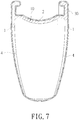
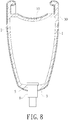
- the surface of the semi-finished carbon fiber rim covered by the carbon fiber cloth (20) is treated by, for example, spraying a protective layer and surface polishing etc., to obtain a finishing carbon fiber rim (in Figs. 6-8 ).
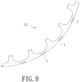
- plural through grooves (7) are formed by milling in the step C. These through grooves (7) are located at positions on the side walls (1) above the connecting wall (2) and corresponding to each of the through holes (4) (please refer to Fig. 9 ).
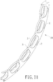
- the positions of the milled through holes (4) are changed in the step C. That is, the through holes (4) are formed by milling along the two side walls (1) of the rim frame's embryo at a predetermined interval (please referring to Fig. 10 and Fig. 11 ). Those spoke coupling holes (5) are milled and formed on the inner rim wall (3). Each of the spoke coupling holes (5) is not disposed at positions corresponding to any one of the through holes (4) but at positions between the adjacent two through holes (4).
- the inner rim wall (3) between the spoke coupling holes (5) is arcuately recessed toward the connecting wall (2) (please referring to Fig. 10 ) or arcuately protruded away from the connecting wall (2) (please referring to Fig. 11 ).
- the material of the metal substrate is one of aluminum alloy and magnesium alloy.
- the magnesium alloy is a highly active metal and can be easily oxidized. Therefore, the magnesium alloy cannot be exposed in the air for a long time.
- the carbon fiber layer formed by covering carbon fiber clothes on the magnesium alloy can prevent the magnesium alloy from oxidizing and increase the durability thereof.
- the structure of the carbon fiber rim made by the method described above comprises a rim frame (10) and a carbon fiber layer (30) covered thereon.
- the rim frame (10) comprises two side walls (1), a connecting wall (2) connecting opposite terminal surfaces of the side walls (1), an inner rim wall (3) connecting the radial inner edges of the side walls (1) to form a space surrounded by the side walls (1), the connecting wall (2), and the inner rim wall (3), plural through holes (4), and plural spoke coupling holes (5).
- These through holes (4) are formed by milling along the two side walls (1) of the rim frame (10) at a predetermined interval.
- the spoke coupling holes (5) are formed on the inner rim wall (3) and at positions not corresponding to any through hole (4) but between the adjacent two through holes (4).
- the carbon fiber layer (30) covers a surface of the rim frame (10) and the through holes (4).
- the inner rim wall (3) between the spoke coupling holes (5) is arcuately recessed toward the connecting wall (2).
- the inner rim wall (3) between the spoke coupling holes (5) also can be designed to arcuately protruded away from the connecting wall (2).
- the difference between another structure of the carbon fiber rim made by the method of manufacturing the carbon fiber rim of this invention and the structure of the carbon fiber rim above is that the through holes (4) are formed by milling along the two side walls (1) and the inner rim walls (3) at a predetermined interval. Therefore, the range of each through hole (4) covers the two side walls (1) and the inner rim walls (3).
- the spoke coupling holes (5) is formed by milling on the inner rim wall (3).
- the spoke coupling holes (5) and the through holes (4) are alternatively disposed to let the two sides of the spoke coupling holes (5) are both adjacent to the through holes (4).
- plural through grooves (7) are formed on the rim frame (10) by milling.
- the positions of the through grooves (7) are at the side walls (1) above the connecting wall (2) and corresponding to the positions of each through holes (4) (please referring to Fig. 9 ).
- the rim frame (10) is made of aluminum alloy or magnesium alloy.
- the metal strip comprises two side walls (1), a connecting wall (2) connecting opposite terminal surfaces of the side walls (1), an inner rim wall (3) connecting the radial inner edges of the side walls (1) to form a space surrounded by the side walls (1), the connecting wall (2), and the inner rim wall (3).
- the meaning of the "width' are the distance between the two side walls (1), and the meaning of the "height" is the distance from the bottom to the top of the side walls (1).
- the rim frame's embryo is milled to form through holes (4) including the two side walls (1) and the inner rim wall (3) as well as the spoke coupling holes (5) on the inner rim walls (3).
- the spoke coupling holes (5) and the through holes (4) are disposed alternatively to form the rim frame (10).
- Spoke coupling elements (6) are disposed in each of the spoke coupling holes (5).
- the surface of the rim frame (10) was roughened, and a carbon fiber cloth (20) trimmed to a predetermined shape is covered on the surface of the rim frame (10) as well as the through holes (4).
- the layer number of the carbon fiber cloth (20) was 1.
- the rim frame (10) was placed in a mold and heatset to form a semi-finished carbon fiber rim. After the surface treatment, a finished carbon fiber rim was obtained.
- the carbon fiber rim having a rim frame inside made by the method of this invention has a much shorter manufacturing time, and the weight thereof is less than the traditional carbon rim.
- the carbon fiber rim was 2100 km more than the traditional carbon fiber rim.
- the carbon fiber rim of this invention is overall increased by 30% compared to the traditional carbon fiber rim.
Landscapes
- Engineering & Computer Science (AREA)
- Chemical & Material Sciences (AREA)
- Mechanical Engineering (AREA)
- Composite Materials (AREA)
- Materials Engineering (AREA)
- Laminated Bodies (AREA)
- Inorganic Fibers (AREA)
Claims (10)
- Verfahren zur Herstellung von Kohlefaser-Felgen, wobei das Verfahren die folgenden Schritte aufweist:A. Ausformen eines Metallstreifens mit einer erforderlichen Form durch Erhitzen eines Metallsubstrats auf eine formbare Temperatur und anschließendes Extrudieren, wobei der Metallstreifen zwei Seitenwände (1), eine die gegenüberliegenden Endflächen der Seitenwände (1) verbindende Verbindungswand (2) und eine die radialen Innenkanten der Seitenwände (1) verbindende, innere Felgenwand (3) zum Ausbilden eines von den Seitenwänden (1), der Verbindungswand (2) und der inneren Felgenwand (3) begrenzten Raumes aufweist;B. Verbinden von zwei Enden des Streifens, derart, dass ein Kreis als Felgenrahmen-Rohling ausgebildet ist;C. Ausformen von Löchern (4) und Speichenverbindungslöchern (5) durch Fräsen des Felgenrahmen-Rohlings zu einem Felgenrahmen (10), wobei die Speichenverbindungslöcher (5) an der inneren Felgenwand (3) und an einer derartigen Stelle ausgebildet ist, dass die Speichenverbindungslöcher (5) nicht auf die Durchgangslöcher (4) ausgerichtet sind, sondern zwischen je zwei benachbarten Durchgangslöchern (4) angeordnet sind, und wobei im jeweiligen Speichenverbindungsloch (5) ein Speichenverbindungselement (6) vorgesehen ist;
dadurch gekennzeichnet,
dass das Verfahren ferner die folgenden Schritte aufweist:D. Oberflächenaufrauungsbehandeln des mit den Durchgangslöchern (4) und den Speichenverbindungslöchern (5) versehenen Felgenrahmens (10), um die Rauigkeit einer Oberfläche des Felgenrahmens (10) zu erhöhen;E. Beschichten der Oberfläche des Felgenrahmens (10) mit einem in einer vorgegebenen Form zugeschnittenen Kohlefaserstoff (20), wobei die Durchgangslöcher (4) gleichzeitig abgedeckt werden;F. Heißfixieren, wobei der mit dem Kohlefaserstoff (20) beschichtete Felgenrahmen (10) in einer Form eingelegt und zur Bildung einer Kohlefaserschicht (30) erwärmt wird, wodurch sich eine halbfertige Kohlefaserfelge ergibt;G. Oberflächenbehandeln der mit dem Kohlefaserstoff (20) beschichteten Kohlefaserfelge, wodurch ein Fertigprodukt der Kohlefaserfelge eines Fahrrads hergestellt ist. - Verfahren nach Anspruch 1,
dadurch gekennzeichnet,
dass die Durchgangslöcher (4) durch Fräsen entlang der beiden Seitenwände (1) des Rohlings des Felgenrahmens in einem vorbestimmten Abstand ausgebildet sind oder durch Fräsen entlang der beiden Seitenwände (1) and der inneren Felgenwand (3) des Rohlings des Felgenrahmens in einem vorbestimmten Abstand so ausgebildet sind, dass die beiden Seitenwände (1) und die innere Felgenwand (3) im Bereich jedes der Durchgangslöcher (4) liegen. - Verfahren nach Anspruch 1 oder 2,
dadurch gekennzeichnet,
dass das Material des Metallsubstrats aus einer Gruppe ausgewählt ist, die eine Aluminiumlegierung und eine Magnesiumlegierung aufweist. - Verfahren nach Anspruch 1 oder 2,
dadurch gekennzeichnet,
dass das Oberflächenbehandeln einen Schritt zum Polieren der Oberfläche der halbfertigen Kohlefaserfelge und einen Schritt zum Aufbringen einer Schutzschicht auf die Oberfläche der halbfertigen Kohlefaserfelge beinhaltet. - Verfahren nach Anspruch 1 oder 2,
dadurch gekennzeichnet,
dass ein bis zwei Schichten des Kohlefaserstoffs (20) auf den Felgenrahmen (10) aufgebracht werden. - Verfahren nach Anspruch 1 oder 2,
dadurch gekennzeichnet,
dass die zwischen den Speichenverbindungslöchern (5) befindliche, innere Felgenwand (3) bogenförmig vertieft zur Verbindungswand (2) hin angeordnet oder weg von der Verbindungswand (2) bogenförmig vorstehend ausgebildet ist. - Verfahren nach Anspruch 6,
dadurch gekennzeichnet,
dass Durchgangsbohrungen (7) durch Fräsen des Felgenrahmens (10) ausgebildet und an den Seitenwänden (1) über der Verbindungswand (2) angeordnet sind, wobei jede der Durchgangsbohrungen (7) dem jeweiligen Durchgangsloch (4) positionsmäßig entspricht. - Verfahren nach Anspruch 5,
dadurch gekennzeichnet,
dass Durchgangsbohrungen (7) durch Fräsen des Felgenrahmens (10) ausgebildet und an den Seitenwänden (1) über der Verbindungswand (2) angeordnet sind, wobei jede der Durchgangsbohrungen (7) dem jeweiligen Durchgangsloch (4) positionsmäßig entspricht. - Verfahren nach Anspruch 1 oder 2,
dadurch gekennzeichnet,
dass Durchgangsbohrungen (7) durch Fräsen des Felgenrahmens (10) ausgebildet und an den Seitenwänden (1) über der Verbindungswand (2) angeordnet sind, wobei jede der Durchgangsbohrungen (7) dem jeweiligen Durchgangsloch (4) positionsmäßig entspricht. - Kohlefaserfelge, die nach einem der Ansprüche 1 bis 9 hergestellt ist und einen Felgenrahmen (10) und eine auf diesen aufgebrachte Kohlefaserschicht (30) aufweist, wobei der Felgenrahmen (10) zwei Seitenwände (1), eine die gegenüberliegenden Endflächen der Seitenwände (1) verbindende Verbindungswand (2), eine die radialen Innenkanten der Seitenwände (1) verbindende, innere Felgenwand (3) zum Ausbilden eines von den Seitenwänden (1), der Verbindungswand (2) und der inneren Felgenwand (3) begrenzten Raumes, eine Mehrzahl von Durchgangslöchern (4) und eine Mehrzahl von Speichenverbindungslöchern (5) aufweist,
wobei die Speichenverbindungslöcher (5) an der inneren Felgenwand (3) und an einer derartigen Stelle ausgebildet ist, dass die Speichenverbindungslöcher (5) nicht auf die Durchgangslöcher (4) ausgerichtet sind, sondern zwischen den benachbarten Durchgangslöchern (4) angeordnet sind, und wobei im jeweiligen Speichenverbindungsloch (5) ein Speichenverbindungselement (6) vorgesehen ist; und
wobei die Kohlefaserschicht (30) auf eine Oberfläche des Felgenrahmens (10) aufgebracht ist und die Durchgangslöcher (4) abdeckt, wobei die Speichenverbindungselemente (6) durch die Kohlefaserschicht (30) hindurchgehen, um die Kohlefaserschicht (30) an der Beschichtungsstelle zu befestigen.
Priority Applications (2)
| Application Number | Priority Date | Filing Date | Title |
|---|---|---|---|
| EP15183378.7A EP3138697B1 (de) | 2015-09-01 | 2015-09-01 | Herstellungsverfahren und -struktur von kohlenstofffaserfelgen |
| PL15183378T PL3138697T3 (pl) | 2015-09-01 | 2015-09-01 | Sposób wytwarzania oraz konstrukcja obręczy z włókna węglowego |
Applications Claiming Priority (1)
| Application Number | Priority Date | Filing Date | Title |
|---|---|---|---|
| EP15183378.7A EP3138697B1 (de) | 2015-09-01 | 2015-09-01 | Herstellungsverfahren und -struktur von kohlenstofffaserfelgen |
Publications (2)
| Publication Number | Publication Date |
|---|---|
| EP3138697A1 EP3138697A1 (de) | 2017-03-08 |
| EP3138697B1 true EP3138697B1 (de) | 2017-12-27 |
Family
ID=54064140
Family Applications (1)
| Application Number | Title | Priority Date | Filing Date |
|---|---|---|---|
| EP15183378.7A Not-in-force EP3138697B1 (de) | 2015-09-01 | 2015-09-01 | Herstellungsverfahren und -struktur von kohlenstofffaserfelgen |
Country Status (2)
| Country | Link |
|---|---|
| EP (1) | EP3138697B1 (de) |
| PL (1) | PL3138697T3 (de) |
Families Citing this family (16)
| Publication number | Priority date | Publication date | Assignee | Title |
|---|---|---|---|---|
| US11098691B2 (en) | 2017-02-03 | 2021-08-24 | General Electric Company | Methods for manufacturing wind turbine rotor blades and components thereof |
| US10830206B2 (en) | 2017-02-03 | 2020-11-10 | General Electric Company | Methods for manufacturing wind turbine rotor blades and components thereof |
| CN106904046A (zh) * | 2017-03-24 | 2017-06-30 | 厦门集质复材科技有限公司 | 一种碳纤维轮辋 |
| DE102017115246B4 (de) * | 2017-07-07 | 2019-05-09 | Alex Global Technology, Inc. | Verbundfahrradfelge |
| US10920745B2 (en) | 2017-11-21 | 2021-02-16 | General Electric Company | Wind turbine rotor blade components and methods of manufacturing the same |
| US11248582B2 (en) | 2017-11-21 | 2022-02-15 | General Electric Company | Multiple material combinations for printed reinforcement structures of rotor blades |
| US11040503B2 (en) | 2017-11-21 | 2021-06-22 | General Electric Company | Apparatus for manufacturing composite airfoils |
| US10773464B2 (en) | 2017-11-21 | 2020-09-15 | General Electric Company | Method for manufacturing composite airfoils |
| US10913216B2 (en) | 2017-11-21 | 2021-02-09 | General Electric Company | Methods for manufacturing wind turbine rotor blade panels having printed grid structures |
| US10821652B2 (en) | 2017-11-21 | 2020-11-03 | General Electric Company | Vacuum forming mold assembly and method for creating a vacuum forming mold assembly |
| US10865769B2 (en) | 2017-11-21 | 2020-12-15 | General Electric Company | Methods for manufacturing wind turbine rotor blade panels having printed grid structures |
| US11390013B2 (en) | 2017-11-21 | 2022-07-19 | General Electric Company | Vacuum forming mold assembly and associated methods |
| US11668275B2 (en) | 2017-11-21 | 2023-06-06 | General Electric Company | Methods for manufacturing an outer skin of a rotor blade |
| CN108068540A (zh) * | 2017-12-28 | 2018-05-25 | 厦门鸿基伟业复材科技有限公司 | 一种碳纤维汽车轮毂结构 |
| US10821696B2 (en) | 2018-03-26 | 2020-11-03 | General Electric Company | Methods for manufacturing flatback airfoils for wind turbine rotor blades |
| US11035339B2 (en) | 2018-03-26 | 2021-06-15 | General Electric Company | Shear web assembly interconnected with additive manufactured components |
Family Cites Families (4)
| Publication number | Priority date | Publication date | Assignee | Title |
|---|---|---|---|---|
| TW200743590A (en) | 2006-05-25 | 2007-12-01 | Advanced Int Multitech Co Ltd | Method of making bike rims |
| TW200950990A (en) | 2008-06-13 | 2009-12-16 | Sumo Technology Corp | Method of manufacturing bike rim and its structure |
| FR2962688B1 (fr) * | 2010-07-13 | 2012-08-17 | Mavic Sas | Jante ou portion de jante realisee en materiau composite |
| US9403404B2 (en) * | 2014-01-28 | 2016-08-02 | Po-Chien Lin | Carbon fiber rim and method of manufacturing the same |
-
2015
- 2015-09-01 EP EP15183378.7A patent/EP3138697B1/de not_active Not-in-force
- 2015-09-01 PL PL15183378T patent/PL3138697T3/pl unknown
Non-Patent Citations (1)
| Title |
|---|
| None * |
Also Published As
| Publication number | Publication date |
|---|---|
| PL3138697T3 (pl) | 2018-06-29 |
| EP3138697A1 (de) | 2017-03-08 |
Similar Documents
| Publication | Publication Date | Title |
|---|---|---|
| EP3138697B1 (de) | Herstellungsverfahren und -struktur von kohlenstofffaserfelgen | |
| CN106457887B (zh) | 无气轮胎及其制造方法 | |
| ES2340463T3 (es) | Llanta de composite. | |
| US5851459A (en) | Method for manufacturing cranks for bicycles | |
| CN220362849U (zh) | 一种碳纤维复合材料的预成型模具与成型模具 | |
| JP2021513486A (ja) | 自転車の構成要素を製造するための方法、自転車の構成要素および自転車のチェーンセット | |
| CN106427391A (zh) | 碳纤维轮圈的制造方法及其结构 | |
| US9770939B2 (en) | Manufacturing method and structure of carbon fiber rims | |
| TWI641511B (zh) | 碳纖維輪圈之製造方法及其結構 | |
| CN103963559A (zh) | 一种新型碳纤维轮辋及其生产工艺 | |
| US10252570B2 (en) | Bicycle rim | |
| EP2020306B1 (de) | Motorradfelge und Verfahren zu ihrer Herstellung | |
| JP2007508183A (ja) | 乗物用ホイールのリムおよびその製造方法 | |
| US20060267396A1 (en) | Wheel, especially a light metal wheel | |
| US9403404B2 (en) | Carbon fiber rim and method of manufacturing the same | |
| US20170253078A1 (en) | Lightweight process of manufacturing bicycle's rims and rim structure manufactured thereby | |
| US9751582B2 (en) | Bicycle assembly with bottom bracket area | |
| US8048355B2 (en) | Method of making a bicycle rim | |
| KR101394875B1 (ko) | 일체형 탄소섬유 복합체 휠의 제조방법 및 그로부터 제조된 일체형 휠 | |
| TWI569988B (zh) | 自行車輪圈輕量化製程及其輪圈結構 | |
| CN210062079U (zh) | 一种带倒勾的碳纤维车圈 | |
| CN210823264U (zh) | 复合材容器 | |
| CN211843942U (zh) | 一种碳纤维轮圈 | |
| CN101879567B (zh) | 复合材轮圈的制造方法及复合材轮圈 | |
| JP3726792B2 (ja) | ステアリングホイール |
Legal Events
| Date | Code | Title | Description |
|---|---|---|---|
| PUAI | Public reference made under article 153(3) epc to a published international application that has entered the european phase |
Free format text: ORIGINAL CODE: 0009012 |
|
| 17P | Request for examination filed |
Effective date: 20160321 |
|
| AK | Designated contracting states |
Kind code of ref document: A1 Designated state(s): AL AT BE BG CH CY CZ DE DK EE ES FI FR GB GR HR HU IE IS IT LI LT LU LV MC MK MT NL NO PL PT RO RS SE SI SK SM TR |
|
| AX | Request for extension of the european patent |
Extension state: BA ME |
|
| GRAP | Despatch of communication of intention to grant a patent |
Free format text: ORIGINAL CODE: EPIDOSNIGR1 |
|
| INTG | Intention to grant announced |
Effective date: 20170608 |
|
| RIN1 | Information on inventor provided before grant (corrected) |
Inventor name: CHEN, WEI-CHIN |
|
| GRAS | Grant fee paid |
Free format text: ORIGINAL CODE: EPIDOSNIGR3 |
|
| GRAA | (expected) grant |
Free format text: ORIGINAL CODE: 0009210 |
|
| AK | Designated contracting states |
Kind code of ref document: B1 Designated state(s): AL AT BE BG CH CY CZ DE DK EE ES FI FR GB GR HR HU IE IS IT LI LT LU LV MC MK MT NL NO PL PT RO RS SE SI SK SM TR |
|
| REG | Reference to a national code |
Ref country code: GB Ref legal event code: FG4D |
|
| REG | Reference to a national code |
Ref country code: CH Ref legal event code: EP |
|
| REG | Reference to a national code |
Ref country code: AT Ref legal event code: REF Ref document number: 957955 Country of ref document: AT Kind code of ref document: T Effective date: 20180115 |
|
| REG | Reference to a national code |
Ref country code: IE Ref legal event code: FG4D |
|
| REG | Reference to a national code |
Ref country code: DE Ref legal event code: R096 Ref document number: 602015006976 Country of ref document: DE |
|
| REG | Reference to a national code |
Ref country code: CH Ref legal event code: NV Representative=s name: PATENTANWAELTE SCHAAD, BALASS, MENZL AND PARTN, CH |
|
| REG | Reference to a national code |
Ref country code: NL Ref legal event code: FP |
|
| PG25 | Lapsed in a contracting state [announced via postgrant information from national office to epo] |
Ref country code: LT Free format text: LAPSE BECAUSE OF FAILURE TO SUBMIT A TRANSLATION OF THE DESCRIPTION OR TO PAY THE FEE WITHIN THE PRESCRIBED TIME-LIMIT Effective date: 20171227 Ref country code: NO Free format text: LAPSE BECAUSE OF FAILURE TO SUBMIT A TRANSLATION OF THE DESCRIPTION OR TO PAY THE FEE WITHIN THE PRESCRIBED TIME-LIMIT Effective date: 20180327 Ref country code: FI Free format text: LAPSE BECAUSE OF FAILURE TO SUBMIT A TRANSLATION OF THE DESCRIPTION OR TO PAY THE FEE WITHIN THE PRESCRIBED TIME-LIMIT Effective date: 20171227 |
|
| REG | Reference to a national code |
Ref country code: LT Ref legal event code: MG4D |
|
| PG25 | Lapsed in a contracting state [announced via postgrant information from national office to epo] |
Ref country code: RS Free format text: LAPSE BECAUSE OF FAILURE TO SUBMIT A TRANSLATION OF THE DESCRIPTION OR TO PAY THE FEE WITHIN THE PRESCRIBED TIME-LIMIT Effective date: 20171227 Ref country code: GR Free format text: LAPSE BECAUSE OF FAILURE TO SUBMIT A TRANSLATION OF THE DESCRIPTION OR TO PAY THE FEE WITHIN THE PRESCRIBED TIME-LIMIT Effective date: 20180328 Ref country code: BG Free format text: LAPSE BECAUSE OF FAILURE TO SUBMIT A TRANSLATION OF THE DESCRIPTION OR TO PAY THE FEE WITHIN THE PRESCRIBED TIME-LIMIT Effective date: 20180327 Ref country code: HR Free format text: LAPSE BECAUSE OF FAILURE TO SUBMIT A TRANSLATION OF THE DESCRIPTION OR TO PAY THE FEE WITHIN THE PRESCRIBED TIME-LIMIT Effective date: 20171227 Ref country code: LV Free format text: LAPSE BECAUSE OF FAILURE TO SUBMIT A TRANSLATION OF THE DESCRIPTION OR TO PAY THE FEE WITHIN THE PRESCRIBED TIME-LIMIT Effective date: 20171227 |
|
| PG25 | Lapsed in a contracting state [announced via postgrant information from national office to epo] |
Ref country code: CY Free format text: LAPSE BECAUSE OF FAILURE TO SUBMIT A TRANSLATION OF THE DESCRIPTION OR TO PAY THE FEE WITHIN THE PRESCRIBED TIME-LIMIT Effective date: 20171227 Ref country code: CZ Free format text: LAPSE BECAUSE OF FAILURE TO SUBMIT A TRANSLATION OF THE DESCRIPTION OR TO PAY THE FEE WITHIN THE PRESCRIBED TIME-LIMIT Effective date: 20171227 Ref country code: ES Free format text: LAPSE BECAUSE OF FAILURE TO SUBMIT A TRANSLATION OF THE DESCRIPTION OR TO PAY THE FEE WITHIN THE PRESCRIBED TIME-LIMIT Effective date: 20171227 Ref country code: SK Free format text: LAPSE BECAUSE OF FAILURE TO SUBMIT A TRANSLATION OF THE DESCRIPTION OR TO PAY THE FEE WITHIN THE PRESCRIBED TIME-LIMIT Effective date: 20171227 Ref country code: EE Free format text: LAPSE BECAUSE OF FAILURE TO SUBMIT A TRANSLATION OF THE DESCRIPTION OR TO PAY THE FEE WITHIN THE PRESCRIBED TIME-LIMIT Effective date: 20171227 |
|
| PG25 | Lapsed in a contracting state [announced via postgrant information from national office to epo] |
Ref country code: SM Free format text: LAPSE BECAUSE OF FAILURE TO SUBMIT A TRANSLATION OF THE DESCRIPTION OR TO PAY THE FEE WITHIN THE PRESCRIBED TIME-LIMIT Effective date: 20171227 Ref country code: IS Free format text: LAPSE BECAUSE OF FAILURE TO SUBMIT A TRANSLATION OF THE DESCRIPTION OR TO PAY THE FEE WITHIN THE PRESCRIBED TIME-LIMIT Effective date: 20180427 |
|
| REG | Reference to a national code |
Ref country code: FR Ref legal event code: PLFP Year of fee payment: 4 |
|
| REG | Reference to a national code |
Ref country code: DE Ref legal event code: R097 Ref document number: 602015006976 Country of ref document: DE |
|
| PLBE | No opposition filed within time limit |
Free format text: ORIGINAL CODE: 0009261 |
|
| STAA | Information on the status of an ep patent application or granted ep patent |
Free format text: STATUS: NO OPPOSITION FILED WITHIN TIME LIMIT |
|
| PG25 | Lapsed in a contracting state [announced via postgrant information from national office to epo] |
Ref country code: DK Free format text: LAPSE BECAUSE OF FAILURE TO SUBMIT A TRANSLATION OF THE DESCRIPTION OR TO PAY THE FEE WITHIN THE PRESCRIBED TIME-LIMIT Effective date: 20171227 |
|
| PGFP | Annual fee paid to national office [announced via postgrant information from national office to epo] |
Ref country code: SE Payment date: 20181024 Year of fee payment: 12 Ref country code: PL Payment date: 20180723 Year of fee payment: 4 |
|
| 26N | No opposition filed |
Effective date: 20180928 |
|
| PG25 | Lapsed in a contracting state [announced via postgrant information from national office to epo] |
Ref country code: SI Free format text: LAPSE BECAUSE OF FAILURE TO SUBMIT A TRANSLATION OF THE DESCRIPTION OR TO PAY THE FEE WITHIN THE PRESCRIBED TIME-LIMIT Effective date: 20171227 |
|
| PG25 | Lapsed in a contracting state [announced via postgrant information from national office to epo] |
Ref country code: MC Free format text: LAPSE BECAUSE OF FAILURE TO SUBMIT A TRANSLATION OF THE DESCRIPTION OR TO PAY THE FEE WITHIN THE PRESCRIBED TIME-LIMIT Effective date: 20171227 |
|
| REG | Reference to a national code |
Ref country code: BE Ref legal event code: MM Effective date: 20180930 |
|
| REG | Reference to a national code |
Ref country code: IE Ref legal event code: MM4A |
|
| PG25 | Lapsed in a contracting state [announced via postgrant information from national office to epo] |
Ref country code: LU Free format text: LAPSE BECAUSE OF NON-PAYMENT OF DUE FEES Effective date: 20180901 |
|
| PG25 | Lapsed in a contracting state [announced via postgrant information from national office to epo] |
Ref country code: IE Free format text: LAPSE BECAUSE OF NON-PAYMENT OF DUE FEES Effective date: 20180901 |
|
| PG25 | Lapsed in a contracting state [announced via postgrant information from national office to epo] |
Ref country code: BE Free format text: LAPSE BECAUSE OF NON-PAYMENT OF DUE FEES Effective date: 20180930 |
|
| PGFP | Annual fee paid to national office [announced via postgrant information from national office to epo] |
Ref country code: IT Payment date: 20190917 Year of fee payment: 5 Ref country code: FR Payment date: 20190927 Year of fee payment: 5 |
|
| PGFP | Annual fee paid to national office [announced via postgrant information from national office to epo] |
Ref country code: GB Payment date: 20190829 Year of fee payment: 5 |
|
| PG25 | Lapsed in a contracting state [announced via postgrant information from national office to epo] |
Ref country code: MT Free format text: LAPSE BECAUSE OF NON-PAYMENT OF DUE FEES Effective date: 20180901 |
|
| PG25 | Lapsed in a contracting state [announced via postgrant information from national office to epo] |
Ref country code: TR Free format text: LAPSE BECAUSE OF FAILURE TO SUBMIT A TRANSLATION OF THE DESCRIPTION OR TO PAY THE FEE WITHIN THE PRESCRIBED TIME-LIMIT Effective date: 20171227 |
|
| REG | Reference to a national code |
Ref country code: NL Ref legal event code: MM Effective date: 20191001 |
|
| PG25 | Lapsed in a contracting state [announced via postgrant information from national office to epo] |
Ref country code: PT Free format text: LAPSE BECAUSE OF FAILURE TO SUBMIT A TRANSLATION OF THE DESCRIPTION OR TO PAY THE FEE WITHIN THE PRESCRIBED TIME-LIMIT Effective date: 20171227 |
|
| PG25 | Lapsed in a contracting state [announced via postgrant information from national office to epo] |
Ref country code: RO Free format text: LAPSE BECAUSE OF FAILURE TO SUBMIT A TRANSLATION OF THE DESCRIPTION OR TO PAY THE FEE WITHIN THE PRESCRIBED TIME-LIMIT Effective date: 20171227 Ref country code: SE Free format text: LAPSE BECAUSE OF FAILURE TO SUBMIT A TRANSLATION OF THE DESCRIPTION OR TO PAY THE FEE WITHIN THE PRESCRIBED TIME-LIMIT Effective date: 20171227 Ref country code: HU Free format text: LAPSE BECAUSE OF FAILURE TO SUBMIT A TRANSLATION OF THE DESCRIPTION OR TO PAY THE FEE WITHIN THE PRESCRIBED TIME-LIMIT; INVALID AB INITIO Effective date: 20150901 Ref country code: MK Free format text: LAPSE BECAUSE OF NON-PAYMENT OF DUE FEES Effective date: 20171227 |
|
| PG25 | Lapsed in a contracting state [announced via postgrant information from national office to epo] |
Ref country code: NL Free format text: LAPSE BECAUSE OF NON-PAYMENT OF DUE FEES Effective date: 20191001 Ref country code: AL Free format text: LAPSE BECAUSE OF FAILURE TO SUBMIT A TRANSLATION OF THE DESCRIPTION OR TO PAY THE FEE WITHIN THE PRESCRIBED TIME-LIMIT Effective date: 20171227 |
|
| PGFP | Annual fee paid to national office [announced via postgrant information from national office to epo] |
Ref country code: DE Payment date: 20200914 Year of fee payment: 6 |
|
| PGFP | Annual fee paid to national office [announced via postgrant information from national office to epo] |
Ref country code: CH Payment date: 20200910 Year of fee payment: 6 |
|
| GBPC | Gb: european patent ceased through non-payment of renewal fee |
Effective date: 20200901 |
|
| PG25 | Lapsed in a contracting state [announced via postgrant information from national office to epo] |
Ref country code: FR Free format text: LAPSE BECAUSE OF NON-PAYMENT OF DUE FEES Effective date: 20200930 |
|
| PG25 | Lapsed in a contracting state [announced via postgrant information from national office to epo] |
Ref country code: GB Free format text: LAPSE BECAUSE OF NON-PAYMENT OF DUE FEES Effective date: 20200901 |
|
| PG25 | Lapsed in a contracting state [announced via postgrant information from national office to epo] |
Ref country code: IT Free format text: LAPSE BECAUSE OF NON-PAYMENT OF DUE FEES Effective date: 20200901 |
|
| REG | Reference to a national code |
Ref country code: AT Ref legal event code: MM01 Ref document number: 957955 Country of ref document: AT Kind code of ref document: T Effective date: 20200901 |
|
| REG | Reference to a national code |
Ref country code: AT Ref legal event code: UEP Ref document number: 957955 Country of ref document: AT Kind code of ref document: T Effective date: 20171227 |
|
| PG25 | Lapsed in a contracting state [announced via postgrant information from national office to epo] |
Ref country code: AT Free format text: LAPSE BECAUSE OF NON-PAYMENT OF DUE FEES Effective date: 20200901 |
|
| REG | Reference to a national code |
Ref country code: DE Ref legal event code: R119 Ref document number: 602015006976 Country of ref document: DE |
|
| REG | Reference to a national code |
Ref country code: CH Ref legal event code: PL |
|
| PG25 | Lapsed in a contracting state [announced via postgrant information from national office to epo] |
Ref country code: DE Free format text: LAPSE BECAUSE OF NON-PAYMENT OF DUE FEES Effective date: 20220401 |
|
| PG25 | Lapsed in a contracting state [announced via postgrant information from national office to epo] |
Ref country code: PL Free format text: LAPSE BECAUSE OF NON-PAYMENT OF DUE FEES Effective date: 20190901 Ref country code: LI Free format text: LAPSE BECAUSE OF NON-PAYMENT OF DUE FEES Effective date: 20210930 Ref country code: CH Free format text: LAPSE BECAUSE OF NON-PAYMENT OF DUE FEES Effective date: 20210930 |