EP3138692A1 - Abbildungssystem zur verarbeitung eines mediums - Google Patents
Abbildungssystem zur verarbeitung eines mediums Download PDFInfo
- Publication number
- EP3138692A1 EP3138692A1 EP16180973.6A EP16180973A EP3138692A1 EP 3138692 A1 EP3138692 A1 EP 3138692A1 EP 16180973 A EP16180973 A EP 16180973A EP 3138692 A1 EP3138692 A1 EP 3138692A1
- Authority
- EP
- European Patent Office
- Prior art keywords
- medium
- actuation command
- status parameter
- roller
- imaging system
- Prior art date
- Legal status (The legal status is an assumption and is not a legal conclusion. Google has not performed a legal analysis and makes no representation as to the accuracy of the status listed.)
- Withdrawn
Links
Images


Classifications
-
- H—ELECTRICITY
- H04—ELECTRIC COMMUNICATION TECHNIQUE
- H04N—PICTORIAL COMMUNICATION, e.g. TELEVISION
- H04N1/00—Scanning, transmission or reproduction of documents or the like, e.g. facsimile transmission; Details thereof
- H04N1/00681—Detecting the presence, position or size of a sheet or correcting its position before scanning
- H04N1/00684—Object of the detection
- H04N1/00702—Position
-
- G—PHYSICS
- G06—COMPUTING; CALCULATING OR COUNTING
- G06K—GRAPHICAL DATA READING; PRESENTATION OF DATA; RECORD CARRIERS; HANDLING RECORD CARRIERS
- G06K15/00—Arrangements for producing a permanent visual presentation of the output data, e.g. computer output printers
- G06K15/40—Details not directly involved in printing, e.g. machine management, management of the arrangement as a whole or of its constitutive parts
- G06K15/4065—Managing print media, e.g. determining available sheet sizes
-
- B—PERFORMING OPERATIONS; TRANSPORTING
- B41—PRINTING; LINING MACHINES; TYPEWRITERS; STAMPS
- B41J—TYPEWRITERS; SELECTIVE PRINTING MECHANISMS, i.e. MECHANISMS PRINTING OTHERWISE THAN FROM A FORME; CORRECTION OF TYPOGRAPHICAL ERRORS
- B41J15/00—Devices or arrangements of selective printing mechanisms, e.g. ink-jet printers or thermal printers, specially adapted for supporting or handling copy material in continuous form, e.g. webs
- B41J15/04—Supporting, feeding, or guiding devices; Mountings for web rolls or spindles
-
- B—PERFORMING OPERATIONS; TRANSPORTING
- B65—CONVEYING; PACKING; STORING; HANDLING THIN OR FILAMENTARY MATERIAL
- B65H—HANDLING THIN OR FILAMENTARY MATERIAL, e.g. SHEETS, WEBS, CABLES
- B65H23/00—Registering, tensioning, smoothing or guiding webs
- B65H23/04—Registering, tensioning, smoothing or guiding webs longitudinally
- B65H23/048—Registering, tensioning, smoothing or guiding webs longitudinally by positively actuated movable bars or rollers
-
- B—PERFORMING OPERATIONS; TRANSPORTING
- B65—CONVEYING; PACKING; STORING; HANDLING THIN OR FILAMENTARY MATERIAL
- B65H—HANDLING THIN OR FILAMENTARY MATERIAL, e.g. SHEETS, WEBS, CABLES
- B65H23/00—Registering, tensioning, smoothing or guiding webs
- B65H23/04—Registering, tensioning, smoothing or guiding webs longitudinally
- B65H23/18—Registering, tensioning, smoothing or guiding webs longitudinally by controlling or regulating the web-advancing mechanism, e.g. mechanism acting on the running web
- B65H23/182—Registering, tensioning, smoothing or guiding webs longitudinally by controlling or regulating the web-advancing mechanism, e.g. mechanism acting on the running web in unwinding mechanisms or in connection with unwinding operations
- B65H23/1825—Registering, tensioning, smoothing or guiding webs longitudinally by controlling or regulating the web-advancing mechanism, e.g. mechanism acting on the running web in unwinding mechanisms or in connection with unwinding operations and controlling web tension
-
- B—PERFORMING OPERATIONS; TRANSPORTING
- B65—CONVEYING; PACKING; STORING; HANDLING THIN OR FILAMENTARY MATERIAL
- B65H—HANDLING THIN OR FILAMENTARY MATERIAL, e.g. SHEETS, WEBS, CABLES
- B65H23/00—Registering, tensioning, smoothing or guiding webs
- B65H23/04—Registering, tensioning, smoothing or guiding webs longitudinally
- B65H23/18—Registering, tensioning, smoothing or guiding webs longitudinally by controlling or regulating the web-advancing mechanism, e.g. mechanism acting on the running web
- B65H23/182—Registering, tensioning, smoothing or guiding webs longitudinally by controlling or regulating the web-advancing mechanism, e.g. mechanism acting on the running web in unwinding mechanisms or in connection with unwinding operations
- B65H23/185—Registering, tensioning, smoothing or guiding webs longitudinally by controlling or regulating the web-advancing mechanism, e.g. mechanism acting on the running web in unwinding mechanisms or in connection with unwinding operations motor-controlled
-
- B—PERFORMING OPERATIONS; TRANSPORTING
- B65—CONVEYING; PACKING; STORING; HANDLING THIN OR FILAMENTARY MATERIAL
- B65H—HANDLING THIN OR FILAMENTARY MATERIAL, e.g. SHEETS, WEBS, CABLES
- B65H23/00—Registering, tensioning, smoothing or guiding webs
- B65H23/04—Registering, tensioning, smoothing or guiding webs longitudinally
- B65H23/28—Registering, tensioning, smoothing or guiding webs longitudinally by longitudinally-extending strips, tubes, plates, or wires
-
- G—PHYSICS
- G05—CONTROLLING; REGULATING
- G05B—CONTROL OR REGULATING SYSTEMS IN GENERAL; FUNCTIONAL ELEMENTS OF SUCH SYSTEMS; MONITORING OR TESTING ARRANGEMENTS FOR SUCH SYSTEMS OR ELEMENTS
- G05B11/00—Automatic controllers
- G05B11/01—Automatic controllers electric
- G05B11/36—Automatic controllers electric with provision for obtaining particular characteristics, e.g. proportional, integral, differential
- G05B11/42—Automatic controllers electric with provision for obtaining particular characteristics, e.g. proportional, integral, differential for obtaining a characteristic which is both proportional and time-dependent, e.g. P.I., P.I.D.
-
- G—PHYSICS
- G05—CONTROLLING; REGULATING
- G05B—CONTROL OR REGULATING SYSTEMS IN GENERAL; FUNCTIONAL ELEMENTS OF SUCH SYSTEMS; MONITORING OR TESTING ARRANGEMENTS FOR SUCH SYSTEMS OR ELEMENTS
- G05B13/00—Adaptive control systems, i.e. systems automatically adjusting themselves to have a performance which is optimum according to some preassigned criterion
- G05B13/02—Adaptive control systems, i.e. systems automatically adjusting themselves to have a performance which is optimum according to some preassigned criterion electric
- G05B13/04—Adaptive control systems, i.e. systems automatically adjusting themselves to have a performance which is optimum according to some preassigned criterion electric involving the use of models or simulators
-
- G—PHYSICS
- G06—COMPUTING; CALCULATING OR COUNTING
- G06K—GRAPHICAL DATA READING; PRESENTATION OF DATA; RECORD CARRIERS; HANDLING RECORD CARRIERS
- G06K15/00—Arrangements for producing a permanent visual presentation of the output data, e.g. computer output printers
- G06K15/40—Details not directly involved in printing, e.g. machine management, management of the arrangement as a whole or of its constitutive parts
- G06K15/408—Handling exceptions, e.g. faults
-
- H—ELECTRICITY
- H04—ELECTRIC COMMUNICATION TECHNIQUE
- H04N—PICTORIAL COMMUNICATION, e.g. TELEVISION
- H04N1/00—Scanning, transmission or reproduction of documents or the like, e.g. facsimile transmission; Details thereof
- H04N1/00681—Detecting the presence, position or size of a sheet or correcting its position before scanning
- H04N1/00729—Detection means
- H04N1/00732—Mechanical detectors
-
- H—ELECTRICITY
- H04—ELECTRIC COMMUNICATION TECHNIQUE
- H04N—PICTORIAL COMMUNICATION, e.g. TELEVISION
- H04N1/00—Scanning, transmission or reproduction of documents or the like, e.g. facsimile transmission; Details thereof
- H04N1/00681—Detecting the presence, position or size of a sheet or correcting its position before scanning
- H04N1/00729—Detection means
- H04N1/00734—Optical detectors
-
- H—ELECTRICITY
- H04—ELECTRIC COMMUNICATION TECHNIQUE
- H04N—PICTORIAL COMMUNICATION, e.g. TELEVISION
- H04N1/00—Scanning, transmission or reproduction of documents or the like, e.g. facsimile transmission; Details thereof
- H04N1/00681—Detecting the presence, position or size of a sheet or correcting its position before scanning
- H04N1/00763—Action taken as a result of detection
- H04N1/00774—Adjusting or controlling
- H04N1/00779—Adjusting settings, e.g. mode, feeding rate or type of paper
-
- B—PERFORMING OPERATIONS; TRANSPORTING
- B65—CONVEYING; PACKING; STORING; HANDLING THIN OR FILAMENTARY MATERIAL
- B65H—HANDLING THIN OR FILAMENTARY MATERIAL, e.g. SHEETS, WEBS, CABLES
- B65H2404/00—Parts for transporting or guiding the handled material
- B65H2404/60—Other elements in face contact with handled material
- B65H2404/61—Longitudinally-extending strips, tubes, plates, or wires
- B65H2404/612—Longitudinally-extending strips, tubes, plates, or wires and shaped for curvilinear transport path
-
- B—PERFORMING OPERATIONS; TRANSPORTING
- B65—CONVEYING; PACKING; STORING; HANDLING THIN OR FILAMENTARY MATERIAL
- B65H—HANDLING THIN OR FILAMENTARY MATERIAL, e.g. SHEETS, WEBS, CABLES
- B65H2515/00—Physical entities not provided for in groups B65H2511/00 or B65H2513/00
- B65H2515/30—Forces; Stresses
- B65H2515/31—Tensile forces
-
- B—PERFORMING OPERATIONS; TRANSPORTING
- B65—CONVEYING; PACKING; STORING; HANDLING THIN OR FILAMENTARY MATERIAL
- B65H—HANDLING THIN OR FILAMENTARY MATERIAL, e.g. SHEETS, WEBS, CABLES
- B65H2553/00—Sensing or detecting means
- B65H2553/51—Encoders, e.g. linear
-
- B—PERFORMING OPERATIONS; TRANSPORTING
- B65—CONVEYING; PACKING; STORING; HANDLING THIN OR FILAMENTARY MATERIAL
- B65H—HANDLING THIN OR FILAMENTARY MATERIAL, e.g. SHEETS, WEBS, CABLES
- B65H2557/00—Means for control not provided for in groups B65H2551/00 - B65H2555/00
- B65H2557/20—Calculating means; Controlling methods
- B65H2557/262—Calculating means; Controlling methods with key characteristics based on feed forward control
-
- B—PERFORMING OPERATIONS; TRANSPORTING
- B65—CONVEYING; PACKING; STORING; HANDLING THIN OR FILAMENTARY MATERIAL
- B65H—HANDLING THIN OR FILAMENTARY MATERIAL, e.g. SHEETS, WEBS, CABLES
- B65H2801/00—Application field
- B65H2801/36—Plotting
Definitions
- the invention relates to an imaging system for processing a media, comprising a media transport path, an imaging station arranged along said media transport path, displacement means for controllably displacing the media along the media transport path relative to said imaging station and a controller assembly.
- the media is positioned relative to the imaging station by means of commonly known transport pinches, which are driven by electric motors.
- transport pinches which are driven by electric motors.
- the increasing demands for higher image quality and speed result in increasingly strict demands of positioning precision of the media with respect to the imaging station.
- the print media is stepwise displaced relative to the printing station such that the image can be applied in several swaths.
- print media have to be positioned at the exact required position when the marking material is applied. Any deviation of the position of the print media relative to the printing station may result in a degraded image quality, as a result of misplacement of particles of marking material on the print media.
- EP2125377 (B1 ) discloses an imaging system, wherein a feedback signal is used to correct for incidental errors while a feedforward signal corrects for structural influences that negatively influence the positioning of the media. In practice, it has been found that, especially during continued operation, the accuracy of the positioning of the print media relative to the printing station in the above mentioned imaging system is insufficient to obtain high quality printing.
- US20011/0211031 A1 discloses a method to maintain a constant tension in the medium by adjusting feedback parameters based on the determined torque. Thereto, a tensioning plate is kept within a predefined working range.
- US20011/0211031 A1 aims to accurately control the medium's speed by adjusting the position of the buffer plate.
- a drawback of US20011/0211031 A1 is that the medium positioning is secondary to its speed, resulting in incorrectly overlapping bands of the printed image, when printing in consecutive swaths. These positioning artifacts are often directly visible to the user and reduce the image quality.
- a further drawback is that during long time operation the accuracy of the method in US20011/0211031 A1 is reduced, since the feedback mechanism is arranged to correct for incidental changes, but not for long term gradual changes in the system.
- US 2015/0166289 A1 discloses a control scheme to maintain constant tension in a web medium applying feedback and feedforward control loops. Tension sensors are provided for generating a signal to be used in controlling the torque. US 2015/0166289 A1 suffers from the same drawbacks as US20011/0211031 A1 as it is concerned with tension control and not medium position. This makes US20011/0211031 A1 and US 2015/0166289 A1 less suited for high quality prints applied in the graphic arts industry.
- an imaging system according to claim 1 and a method according to claim 14 are provided.
- the imaging system for processing a medium supplied from a medium roller comprises a media transport path, an imaging station arranged along said media transport path, an actuator for driving the medium roller for controllably displacing the medium along the media transport path relative to said imaging station and a controller assembly.
- Web or sheet media are provided in rolled up form on the medium roller.
- the medium roller pushes the sheet along the transport path towards the imaging station, which comprises one or more print heads for swath-wise printing an image on the web medium.
- the actuator may for example be an electric motor for driving the medium roller around its rotation axis.
- the actuator may directly drive the medium roller or via a transmission unit such as a worm wheel.
- the controller assembly comprises a sensor device for generating a position signal, which position signal represents a position of the medium along the transport path.
- the sensor device thereby senses or measures the advancement of the web medium along the transport path.
- a sensor device may comprise an optical sensor, a roll-motor encoder for determining the angular displacing of the medium roller, or a wheel encoder.
- a processor is provided for processing the position signal from the sensor device.
- the processor and the sensor device may to this end be connected via a wired or wireless connection, such that the processor is arranged to receive the position data determined by the sensor device.
- the actuator is actuated in response to an actuation command generated by the controller assembly.
- the controller assembly is arranged for generating the actuation command and transmitting the actuation command to the actuator.
- the actuator is arranged for displacing the medium roller over an angle or angular range based on the actuation command.
- the actuation command is derivable from a feedback component and a feedforward component.
- the controller assembly especially the processor, is arranged for determining the actuation command from a feedback component and a feedforward component.
- the feedback component is based on a position error being the difference between a position setpoint and the position signal.
- the position setpoint preferably corresponds to the desired position of the medium along the transport path, and, in consequence, to the desired angular position of the medium roller.
- the position setpoint may be input position data or an input signal, such as an input voltage for driving the actuator.
- the feedback component may be used to correct for incidental errors.
- the controller assembly may comprise a feedback filter for generating the feedback component.
- a P, PI, PD, or PID controller may be provided in the feedback filter to correct the actuation command in response to the difference between the position setpoint and the position signal.
- the performance of the imaging system may be increased by determining the current status of the medium on the medium roller and using this current status to estimate what the actuation command should be to advance the medium in the desired manner.
- the processor is further arranged for determining a time dependent status parameter.
- This status parameter represents a status of the medium on the medium roller, and may, for example, comprise information relating to the outer radius, inertia, mass, and/or eccentricity of the medium on the medium roller.
- the status parameter is determined from the position signal, by analyzing the position data generated by the sensor device.
- the status parameter may, in another example, comprise a model, specifically an inverted model system, of the medium and the medium roller.
- the mass of the medium on the medium roller decreases over time and the controller assembly adjust the status parameter accordingly.
- the status parameter during operation continually represents the current status of the imaging system, specifically the mass and/or outer radius of the medium on the medium roller.
- the processor is further arranged for deriving an actuation command estimate based on the status parameter.
- the feedforward component comprises the actuation command estimate.
- the status parameter comprises information regarding the current radius R of the medium on the medium roller, which radius R is used to determine an actuation command. Said actuation commands rotates the medium roller by an angle ⁇ , such that the medium advancement ⁇ R corresponds to a desired or predefined value.
- the status parameter may comprise information relating to the current mass m of the medium on the medium roller, such that an actuation command may be adapted to include the current dynamics of the system based e.g. upon Newton's laws.
- the actuation command estimate accurately provides the desired stepwise advancement of the medium.
- the implementation of the present invention requires little structural adaption of the imaging system and may thus be easily implemented. Thereby the object of the present invention has been achieved.
- the processor when in use and/or during operation, is arranged for continuously adjusting the status parameter in correspondence to a decreasing inertia of the medium roller, specifically the inertia of the medium on the medium roller.
- the status parameter preferably corresponds to the status of one or more physical properties of the medium on the medium roller, especially to the outer radius (or diameter) and/or the mass of the medium on the support roller.
- the status parameter is a time dependent media roll inertia parameter.
- the processor is arranged to continually fit the media roll inertia parameter to the actual media roll inertia by analyzing the sensed position signal.
- the status parameter is time dependent and preferably continually determined and/or adjusted to correspond to the current status of the medium on the medium roller.
- the status parameter accurately represents the medium on the medium roller, allowing for an accurate estimation of the actuation command estimate, and thereby the actuation command, based on this status parameter.
- continual adjustment includes step-wise, intermittent, iterative, or recursive adjustment of the status parameter.
- the status parameter is adjusted in between consecutive advancement steps of the medium, e.g. during the printing of a swath of the image on the medium.
- the feedforward component comprising the actuation command estimate based on the status parameter therefore is arranged for accurately determining the actual step size as executed by the media roll actuator motor to match the input setpoint. This manner of very accurate control allows for high quality printing, as is desired in e.g. the graphic arts industry.
- the processor is further arranged for deriving the time dependent status parameter from the position signal.
- the processor may then analyze the position data obtained by sensor device to derive the status parameter, for example by fitting the position data to a curve or model system.
- the status parameter is iteratively or recursively determined based on a previously determined value of the status parameter and a correction factor based on a difference between the sensed position of the medium and the desired position of the medium. Since the position signal is already used for the feedback component, no additional sensor unit is required, allowing for an easy and cheap implementation of the invention.
- the feedforward component is derived from the position setpoint by means of the status parameter.
- the actuation command estimate therefore approximates the predicted future behavior of the media roll, without taking into account how the load reacts instantaneously.
- the feedback component is derived from the sensed position signal. So, the feedback component directly adjusts the output actuation command in correspondence to how the load of the media roll reacts as derived from the positioned signal, while the feedforward component is derived from the position setpoint in order to estimate or predict the media roll's behavior over longer periods.
- the feedforward loop runs in parallel to the feedback loop and one preferably is independent of the other.
- the controller assembly is arranged for positioning the medium.
- the position of the medium is determined by accuracy of the step spacing during each iteration of the stepwise transport of the medium.
- the controller assembly preferably applies thereto a position setpoint which is compared to a sensed position signal, allowing for a precise positioning of the medium. This is in contrast to e.g. tension or speed control, wherein these latter parameters are accurately controlled to the detriment of the accuracy of the medium position (and/or the positioning step). Accurate stepping improves the image quality.
- the controller assembly further comprises a feedback controller for determining the feedback component based on or from the difference between a position setpoint and the position signal.
- the feedforward component is combined with the feedback component downstream of the feedback controller (i.e. at the output side of the feedback controller).
- the control assembly comprises a feedback control loop and a feedforward control loop for respectively determining the feedback component and the feedforward component, which loops are or run parallel to one another. In other words the feedforward loop bypasses the feedback controller (and in consequence the feedback loop). Both loops are combined at the input of the roll motor to form the actuation command.
- the feedback loop is arranged for determining the feedback component from a difference between the position setpoint and the position signal, which allows the control assembly to correct the motion of roll motor based on its history. This is however always after the fact and thus inaccurate.
- the feedforward loop has been provided.
- the feedforward loop comprises the status parameter, which forms or defines a model system of the media roll, specifically its inertia.
- the model system with its status parameter is continually kept up-to-date by input from the position signal.
- the model system is further derived from the input actuation command to allow continuous correction of the feedforward component.
- the status parameter is derived from a difference between an input actuation command and a feedforward component.
- the status parameter is then continuously adjusted such that said difference is minimized, thereby bringing the model system in correspondence with the actual media roll.
- the feedforward component is further determined by one or more time derivatives of the position setpoint combined with the status parameter(s). By incorporating the temporal variation of the setpoint an accurate prediction of the desired or optimum feedforward component can be made.
- a further advantage of the status parameter is that the start-up time after loading a new media roll is reduced. The model system quickly converges towards realistic or actual values for the media roll. Thereby, productivity is increased.
- the processor is further arranged for deriving the time dependent status parameter from the actuation command.
- a relation between the sensed (or actual) position of the medium and the actuation command may be obtained.
- the status parameter may then comprise a model parameter which allows the processor to determine or predict the medium displacement based on an input actuation command (or vice versa). Since the relation between the actuation command and the status parameter may be determined in the above described manner, the computation time for generating the actuation command may be reduced.
- the processor may be arranged for deriving the actuation command estimate from the status parameter and the position setpoint.
- the position setpoint corresponds to the desired position of the medium, and may in an embodiment be formed by an input signal for driving the actuator. From the position setpoint, the processor may derive the desired medium position, i.e. where the medium is to be positioned in an upcoming advancement step.
- the status parameter provides a relation between the position of the medium and the actuation command.
- the actuation command required to accurately position the medium during the upcoming advancement step is derived or estimated from the position setpoint (preferably from one or more of its time derivatives) and the status parameter.
- the position setpoint may for example be an input signal representing a desired position of the medium or medium roller or be formed by position data, which determines the desired stepwise advancement of the medium. In a basic example, the position setpoint is determined by the desired step size for the medium advancement.
- the processor is further arranged for determining the status parameter based on the position signal and a command error signal, which command error signal is the difference between the actuation command and the actuation command estimate.
- the command error signal corresponds to the deviation of the actuation command estimate and the actual actuation command applied. This difference is compared to the sensed position of the medium to derive a relation between the command error and the sensed position of the medium, which relation is expressed in the status parameter. This allows the controller assembly to adjust the status parameter in response to the actuation command error, further improving the accuracy and reducing the computation time.
- the processor applies an inverted model system of the imaging system for determining the actuation command estimate
- the difference between the actuation command estimate and the actuation command becomes a measure for the accuracy of the model system.
- the computation time for deriving the status parameter may be reduced.
- the convergence time for adjusting the status parameter to the imaging system's properties may be significantly reduced, especially when a recursive least squares algorithm is applied for deriving the status parameter.
- the controller assembly further comprises a memory arranged for storing a status parameter.
- the processor is arranged for determining a subsequent status parameter from the status parameter stored on the memory.
- an initial value or estimate of the status parameter is provided on the memory at the start of the printing operation. Said initial value or estimate is used for iteratively or recursively determining further values of the status parameter.
- the processor may, in another example, determine the status parameter by analyzing the data on the memory, e.g. by fitting this data to a curve or model system. Preferably, an inverted model system of the imaging system is used.
- the inverted model system is arranged to minimize the difference between an actuation command and an actuation command estimate, which actuation command estimate is derived from the position signal sensed in respect of said actuation command, i.e. after actuating the actuator based on said actuation command.
- the inverted model system is arranged to convert a position signal back into the actuation command which positioned the medium at the sensed position.
- the processor is arranged for deriving the actuation command estimate from a time derivative of the position setpoint.
- the position setpoint or position setpoint signal may be converted into a plurality of dynamic properties, such as jerk, acceleration, and/or velocity.
- the plurality of time derivatives allows the processor to accurately model the dynamic behavior of the medium advancement.
- the processor is arranged for determining a setpoint velocity, a setpoint acceleration, and a setpoint jerk from the position setpoint. The processor may then determine a corresponding velocity status parameter, a corresponding acceleration status parameter, and a corresponding jerk status parameter.
- a model system of the imaging system is formed, which is preferably inverse to the actual imaging system. It lies within the scope of the present invention to derive additional time derivatives from the position setpoint to increase the accuracy of estimation of the actuation command.
- the controller assembly and the actuator are arranged for stepwise driving the medium roller.
- the processor is arranged for determining a displacement of the medium per step based on the position signal.
- the imaging system according to the present invention is arranged to determine an actuation command and an actuation command estimate for each step of the advancement of the medium.
- the controller assembly further comprises a repetitive controller arranged for modeling the eccentricity of the medium roller based on the position signal and for adjusting the actuation command in correspondence to the eccentricity of the medium roller.
- a repetitive controller arranged for modeling the eccentricity of the medium roller based on the position signal and for adjusting the actuation command in correspondence to the eccentricity of the medium roller. Since the medium on the medium roller is in practice not fully spherical, its outer radius varies over the circumference of the medium on the medium roller. Further, an eccentricity may be present in one or more components of the drive train for driving the medium roller. To compensate for this variation in radius, the repetitive controller may be arranged to determine said eccentricity by fitting one or more harmonic or periodic base functions to the position signal or position data. The frequency of said base functions is significantly lower than the step frequency of the roller motor, e.g. in the order of magnitude of a revolution period of the medium roller, or higher.
- the eccentricity of the medium roller with the medium By adapting the actuation command to the determined eccentricity of the medium on the medium roller, a precise positioning of the medium is achieved. Basically, once the eccentricity of the medium roller with the medium has been determined or fitted, it can be applied to correct the actuation command for an upcoming advancement step, since the eccentricity repeats cyclically, i.e. with each turn of the medium roller.
- the sensor device comprises an encoder wheel positioned along the transport path between the imaging station and the medium roller.
- the encoder wheel contacts the medium and determines the medium position or advancement based on the sensed revolutions of the encoder wheel.
- the sensor device further comprises an observer for sensing the angular position of the medium roll.
- the observer which may be a roll-motor encoder, determines the rotational position of the medium roller.
- An encoder is arranged for a precise determination of the medium advancement and/or position without affecting the medium transport.
- the imaging system further comprises transport pinch rollers positioned upstream of the medium roller, and a passive buffer device positioned along the transport path between the medium roller and the transport pinch rollers for resiliently engaging the medium.
- the buffer zone is arranged to compensate any tension in the medium.
- a tension sensor is provided which is arranged for sensing the position of the passive buffer. The tension in the medium may then be determined and applied in the feedback or feedforward mechanism in order keep the tension in the medium constant.
- the processor is further arranged for deriving an actuation command estimate by means of an inverted model system of the imaging system.
- the inverted model system is a model or simulation of the actual imaging system in inverted form, such that when a position signal is input to the model system, it yields an actuation command estimate. Said position signal may be obtained by inputting an actuation command to the actual imaging system and sensing the position of the medium or roller.
- the inverted model system comprises the status parameter, which status parameter is adjusted by processor to minimize the difference between the actuation command and the actuation command estimate. This allows for an efficient determination of a model system, which is continually adjusted to correspond to changes in the actual imaging system.
- the controller assembly is arranged to transmit the actuation command to the the actuator to transport the medium a step spacing along the transport path, wherein the step spacing is similar (or substantially equal) to a distance defined by the position setpoint.
- the combined feedback and feedforward control ensures the step spacing is at all times in correspondence with the setpoint, such that the medium may be positioned with great accuracy.
- the invention provides a method for actuating a medium roller in an imaging system, comprising a media transport path and an imaging station arranged along said media transport path.
- the method comprises the steps of:
- stepwise advancement of the medium is controlled by means of a feedback and a feedforward filter or loop.
- the position signal representing the medium position and/or the angular position of the medium roller is compared to the position setpoint, i.e. the desired position, and the deviation between the two determines the feedback and/or feedforward components.
- the method according to the present invention further comprises the step of deriving a time dependent status parameter, which status parameter represents a status of the medium on the medium roller from the position signal and the first actuation command.
- the status parameter adapts to the decreasing inertia or weight of the medium on the medium roller, such that the status parameter at substantially all times accurately represents the status of the medium roller.
- the step of determining the feedforward component according to the present invention further comprises deriving an actuation command estimate from the status parameter and the position setpoint.
- the actuation command estimate predicts or estimates the actuation command required to position the medium at the desired position.
- the relevant properties of the medium roll may be incorporated in the status parameter, which is derived from the position signal.
- an additional radius sensor may be provided to determine the outer radius of the medium roll to increase accuracy.
- the feedforward component is derived from the position signal sensed after actuating the medium roller by means of the first actuation command.
- the medium roller is rotated over an angle determined by the first actuation command, after which the position of the medium and/or the medium roller is determined, e.g. by the sensor device.
- the actuation command estimate is determined from said position signal by means of an adaptive feedforward algorithm.
- the sensed position signal is input to the processor, which applies the adaptive feedforward algorithm to derive an estimate for the upcoming actuation command (for the next advancement step).
- This adaptive feedforward algorithm preferably comprises an inverted model system of the imaging system.
- the inverted model system is an accurate model or simulation of the actual imaging system, but inverted such that the actuation command estimate is substantially similar or equal to the first actuation command. If the inverted model system would be a fully accurate representation of the imaging system, the difference between the actuation command estimate and the first actuation command u would be zero or a value close to zero. As such, the difference between the actuation command estimate and the first actuation command provides a good indication of the accuracy of the model system. This difference or command error signal can thereby be efficiently used to correct the model system.
- the inverted model system comprises the status parameters, which are recursively derived using said command error signal.
- the method comprises the step of transmitting the actuation command to the the actuator, such that the medium is transported a step spacing along the transport path.
- the step spacing corresponds or matches the step spacing or prescribed by the position setpoint. This allows for precise control of the medium's position.
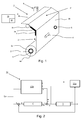
- FIG. 1 A schematic drawing of the imaging system 1 according to the present invention is shown in Fig. 1 .
- the medium roller 2 is located at the bottom of Fig. 1 .
- the medium roller 2 holds the rolled up medium 3a.
- the roller 2 is rotatable by a means of an actuator 4, being the motor 4. From the roller 2, the medium 3 extends towards a pinch roller 6.
- This pinch roller 6 is only used to lead the unspooled medium 3b to a transport pinch 8, when a leading edge of the medium 3 has not yet reached the transport pinch 8.
- the medium 3 passes the sensor device 5, comprising an encoder wheel 5.
- the encoder wheel 5 is a wheel rotatable over the medium 3 and thereby measuring the advancement of the transported medium 3. Upstream from the sensor device 5, a passive buffer device 7 is provided.
- a passive buffer device 7 Upstream from the sensor device 5, a passive buffer device 7 is provided.
- the passive buffer 7 is a metal sheet 7, which pushes against the medium 3b by means of pulley-springs (not shown), thus decreasing the medium-tension to step-error ratio.
- the medium 3 passes then through the transport pinch 8.
- the transport pinch 8 is arranged to rotate and thereby advance the medium 3 in highly accurate steps, such that the medium 3 will be positioned correctly with respect to the print head of the imaging station 9.
- the medium 3 is advanced stepwise below the print head 9, which print head 9 swath-wise applies an image to the surface of the medium 3. Any inaccuracies originating from the step of medium roller 2 will cause the buffer 7 to be displaced with respect to the transport path P. This changes the tension in the medium 3, and affects the medium 3 positioning below the print head 9. This results in a decrease in print quality as the consecutively applied swaths are not properly aligned with respect to one another.
- the position of the buffer 7 with respect to the transport path is a measure for the tension in the medium 3b.
- the sensor device 5 may comprise a tension sensor 7a arranged for sensing the position of the passive buffer 7 and determining the tension in the medium 3 from said position. It is preferred that the controller assembly 10 is arranged for maintaining a substantially constant position of the buffer 7 to ensure accurate positioning of the medium 3b.
- An actuator 4 is provided for driving the medium roller 2.
- the actuator 4 is preferably an electric motor 4, especially an electric DC motor 4, arranged for stepwise rotating the medium roller over an angle based on an input signal or actuation command u.
- the input or actuation command u for the motor 4 is generally a voltage applied to the electric roll motor 4.
- a voltage is applied to over a pinch motor (not shown) for driving the transport pinch roller 8.
- the actuation command u is used for driving the pinch roller 8, such that the web 3 is advanced by means of the pinch roller 8.
- the actuator for driving the medium roller 2 is then formed by the motor for driving the pinch roller 8. When stepping (i.e. when advancing the medium 3 stepwise), the pinch roller 8 is driven such that there is a constant tension between the pinch 8 and the roller 2.
- the imaging system 1 in Fig. 1 comprises a controller assembly 10 for generating said input voltages or actuation commands u, which controller assembly 10 is schematically shown in Fig. 3 .
- the controller assembly 10 comprises a sensor device 5, the output of which is applied for controlling the roll actuator 4.
- the sensor device in Fig. 1 comprises a buffer encoder 7a in the buffer 7 for determining the tension in the medium 3b, as discussed above.
- a buffer encoder 7a on either side of the buffer 7 for accurately determining the tension in the medium 3b from the signals of both buffer encoders 7a.
- the sensor device 5 further comprises a position sensor 5, such as an encoder wheel 5, for determining the position and/or advancement of the medium 3 with respect to the transport path P.
- the sensor device 5 may comprise an angular sensor, such as a roll-motor encoder 4a, for determining the rotational position of the medium roll 2 and/or the medium roll motor 4.
- a pinch encoder may further be provided for determining the angular position of the transport pinch roll 8 or it's motor.
- the sensor device 5 is arranged for generating a position signal (y in Fig. 2 ) representing the position of the medium 3 along the transport path P based on measurements by the encoder wheel 5.
- the position signal y may further include data from the buffer encoder 7a and the roll-motor encoder 4a, which provide a signal representing the tension in the medium 3b and the angular position of the roll-motor 4 and/or medium roller 2.
- Fig. 2 illustrates a control diagram for a controller assembly 10 according to the present invention.
- a setpoint Sp is input to the controller assembly 10 for positioning a medium 3 at a desired position.
- an actuation command u is derived for driving the roller motor 4 to move the medium 3 to the desired position.
- the actuation command u is composed of a feedback component u fb and a feedforward component u ff .
- the feedback component u fb is formed by inputting a position error e to a feedback filter C, while the feedforward component is derived from a forward algorithm 11 b.
- the feedforward algorithm 11 b is adaptive to any changes in the medium 3a on the roller 2 by means of a status parameter determination algorithm 11 a.
- the status parameter determination algorithm 11 a derives a status parameter ⁇ from among others the position signal y, such that the status parameter ⁇ forms an accurate model system of the imaging system 1, specifically of the medium 3a on the roller 2 and preferably the roller 2.
- a position setpoint Sp is used as input on the left hand side of Fig. 2 .
- This setpoint Sp corresponds to the desired position of the medium 3.
- the medium 3 is positioned by rotating the roller 2 of the imaging system 1 to an angular position. Said rotating is performed by inputting an actuation command u to the roller motor 4.
- a position signal y is obtained.
- Said position signal y corresponds for example to the medium 3 position or an angular position of the roller 2, as determined by the sensor device.
- the position signal y is used in a feedback filter or loop.
- the position signal y is compared to the setpoint Sp and their deviation is input to a feedback controller C as the position error e to determine the feedback component u fb .
- the feedback component u fb is combined with a feedforward component u ff to form actuation command u for driving the motor 4.
- the feedforward component u ff is determined by means of a feedforward filter 11 b performed by the processor (11 in Fig. 3 ).
- the processor 11 applies the algorithm 11 b to determine an actuation command estimate u based on a previous actuation command u and the position signal y. From the position signal y, the processor 11 determines a status parameter ⁇ , which is used as input for the algorithm 11 b.
- the status parameter ⁇ is continuously determined from the position signal y by means of an algorithm 11a, such that the value of the status parameter ⁇ corresponds to the current status of the medium 3a on the roller 2.
- the feedforward algorithm 11 b becomes adaptive to any changes in the inertia of the medium 3a on the roller 2.
- the status parameter ⁇ forms an always up-to-date model system of the imaging system 1, thereby allowing for a highly accurate estimation of the desired actuation command u. This enables precise positioning of the medium 3 in the imaging system 1 according to the present invention.
- FIG. 3 A controller assembly according to the present invention is depicted in detailed form in Fig. 3 .
- the control scheme in Fig. 3 is similar to that in Fig. 2 , but Fig. 3 comprises additional features and functionalities, which will be discussed below.
- a fixed feedback controller C is used that stabilizes the system 1 for all inertia's.
- a fixed feedback controller C may be used. This controller C over the buffer 7 makes sure that at low frequencies the buffer 7 stays at a fixed position.
- the feedback controller C is creating a stable loop, but in practice may have a limited bandwidth.
- a feedforward controller 11 is used, and because of the time variations in the system 1, and specifically in the medium 3a on the roller 2, an adaptive feedforward algorithm 11 b is applied to estimate the actuation command u required to maintain the following advancement step similar or even identical to the step before it.
- FIG. 3 a block diagram for the controller assembly 10 according to the present invention is shown.
- a position setpoint Sp or position setpoint signal is input into the controller assembly 10 on the left side of Fig. 3 .
- the position setpoint Sp comprises information representing the desired position of the medium 3 along the transport path P, such as position or step data. Further information representing the desired medium tension at e.g. the buffer 7 maybe provided in the position signal y.
- the position signal y further comprises information representing the desired angular or rotational orientation of the medium roller 2 or its motor 4.
- the position setpoint Sp may comprise one or more input signals or voltages for the actuator 4 for rotating the medium roller 2 over a desired angle.
- the position setpoint Sp may be input prior to operation or during operation in a continuous manner.
- a position signal y is output.
- the position signal y is compared to the position setpoint Sp to determine a position error e.
- the angular position of the medium roller 2 may be determined from the position signal y by means of a Luenberger observer 5a. In practice, the direct measurement of the angular orientation of the roller 2 may be difficult to implement. The status of the medium roller 2 and/or its actuator 4 may then be determined from the position signal y by the observer 5a.
- the angular position and rotational velocity of the actuator 4 and/or the roller 2 with the medium 3a may be derived from the position signal y, as well as from the current running through the motor 4.
- the sensor device 5 provides a tension signal determined by the buffer encoder 7a and an angular signal determined by the angular sensor 4a, which signals are transmitted to the feedback controller C for determining the position error e.
- the position error e represents a deviation between the desired position of the medium 3 and the "actual" position of the medium 3 as determined by the sensor device 5.
- This position error is input to the feedback controller C for generating the feedback component u fb of the actuation command u.
- the feedback filter C comprises a proportional component acting on the magnitude of the error signal and a derivative component acting on the rate of change of the error signal e.
- the resulting feedback component u fb will result in a fast correction of incidental disturbances, while the derivative component introduces enough damping to the controlled system to overcome problems due to overshoot. In imaging systems it is undesired to oscillate a media during positioning thereof and the media should be in the correct position within a relatively small amount of time.
- the feedback controller C comprises a P, PI, PID, ID, or PD controller. It will be appreciated that the feedback controller C in Fig. 3 may be implemented by means of the processor 11, i.e. as a software-based controller, or as a hardware-based feedback filter.
- the controller assembly 10 further comprises a processor 11, which has at least two main functions, namely determining the status parameters ⁇ 1 , ⁇ 2 , ⁇ 3 and deriving the feedforward component u ff formed by the actuation command estimate u.
- the processor 11 is arranged for determining the one or more time dependent status parameters ⁇ 1 , ⁇ 2 , ⁇ 3 , preferably by means of a status parameter determination algorithm 11 a.
- the status parameters ⁇ 1 , ⁇ 2 , ⁇ 3 are arranged to represent a status of the medium 3b on the medium roller 2.
- the status parameters ⁇ 1 , ⁇ 2 , ⁇ 3 are derived from the position signal y as sensed by the sensor device 5, specifically the wheel encoder 5, and from the actuation command u generated by the controller assembly 10.
- the angular position of the roller 2 is determined from the position signal y by means of an observer 5a, such as a Luenberger observer 5a. Such an observer 5a may be applied when a direct measurement of the angular orientation of the roller 2 is not possible or complicated. The angular orientation of the roller 2 is then derived by the observer 5a based on e.g. signals representing the tension in medium 3b, the angular position of the actuator 4, and/or the position of the medium 3.
- the observer 5a outputs the roller orientation signal z, which signal z represents the angular orientation of the medium 3a on the roller 2 (or of the roller 2).
- the observer 5a increases the accuracy of the controller assembly by a precise determination of the medium roller's orientation.
- the position signal y may be used to determine the status parameters ⁇ 1 , ⁇ 2 , ⁇ 3 without use of the observer 5a or the signal z.
- an encoder positioned at the circumference of the medium 3a on the medium roller 2 may be applied.
- the status parameters ⁇ 1 , ⁇ 2 , ⁇ 3 are derived by means of the status parameter determination algorithm 11 a.
- the algorithm 11 a applies as inputs the position signal y and the actuation command u.
- the position signal y may in a preferred embodiment be converted into the roller orientation signal z by means of the observer 5a. Also, both signals y, z may be used.
- the actuation command u may in another embodiment be processed into a command error ⁇ , as will be discussed further on.
- the status parameter ⁇ 1 , ⁇ 2 , ⁇ 3 represents the current status of the medium 3a on the roller 2.
- the status parameter ⁇ 1 , ⁇ 2 , ⁇ 3 may be considered to form an accurate model representation or system of the medium 3a and the roller 2.
- the status parameter determination algorithm 11 a may for example be arranged to obtain the status parameters ⁇ 1 , ⁇ 2 , ⁇ 3 from data formed by or based on one or more of the signals y, u, u, ⁇ , and/or z from sensors 4a, 5, 5a, 7a.
- the processor 11 is then arranged to analyze said data to determine the status parameters ⁇ 1 , ⁇ 2 , ⁇ 3 , for example by fitting the data to a model system or curve.
- the processor 11 applies a recursive least squares algorithm 11 a to recursively determine the status parameters ⁇ 1 , ⁇ 2 , ⁇ 3 .
- a recursive algorithm 11 a has the advantage that computation time is reduced and the status parameters ⁇ 1 , ⁇ 2 , ⁇ 3 may be determined with great accuracy within the time between two consecutive advancement steps.
- a further advantage of the recursive algorithm 11 a is that it requires relatively little processor power, such that a cheap and/or simple processor 11 may be used.
- the status parameters ⁇ 1 , ⁇ 2 , ⁇ 3 may be stored on the memory M for use in the algorithm 11a, for example by recursively determining a status parameter ⁇ 1 , ⁇ 2 , ⁇ 3 from a previously determined status parameter ⁇ 1 , ⁇ 2 , ⁇ 3 stored on the memory M.
- the memory M may further store information or data related to the position setpoint Sp, actuation command u, actuation command estimate u, position signal y, and/or the roller orientation signal z.
- the algorithm 11a is a recursive least squares (RLS) algorithm, which advantageously provides for a rapid and efficient determination of the status parameters ⁇ 1 , ⁇ 2 , ⁇ 3 , as well as a fast convergence of said parameters ⁇ 1 , ⁇ 2 , ⁇ 3 during the start-up phase of the printing process.
- RLS recursive least squares
- the algorithm according to the present invention is especially well suited for printing processing wherein step sizes are varied, as well as for processes wherein operational parameters such as the inertia of the medium roll 3a vary significantly.
- ILC iterative learning control
- ILC requires a number of ILC circuits specifically designed to a specific system, whereas the algorithm according to the present invention may be applied by means of a processor 11. Thereby, the present invention is easy and cheap to implement.
- the actuation command u which may for example be an input voltage V for driving the electric medium roll motor 4, comprises a feedback and feedforward component u fb , u ff .
- the status parameters ⁇ 1 , ⁇ 2 , ⁇ 3 are applied by the processor 11 for determining the feedforward component u ff .
- the position setpoint Sp which for example is the desired angular position of the medium roller 2, is input to the processor 11 to derive an actuation command estimate u ff by means of a feedforward algorithm 11 b.
- the processor 11 determines one or more setpoint parameters d/dt, d 2 /dt 2 , d 3 /dt 3 , such as the time derivatives d/dt, d 2 /dt 2 , d 3 /dt 3 . Any number or order of time derivatives may be applied.
- the processor 11 combines setpoint parameters d/dt, d 2 /dt 2 , d 3 /dt 3 with the status parameters ⁇ 1 , ⁇ 2 , ⁇ 3 to obtain an accurate estimate u of the actuation command u.
- the feedforward algorithm 11 b uses a continuously up-to-date input, such that the estimate u takes into account the decreasing inertia and outer radius of the medium roll 3a as it unspools. As such, the feedforward algorithm 11 b provides an accurate estimate u of the command estimate u, which allows for precise stepping and high quality printing.
- the controller assembly 10 in Fig. 3 further comprises a feedforward controller 11 b, which may be either a hardware or software-based controller.
- the position setpoint Sp is applied as input for determining the feedforward component u ff output by the feedforward controller 11 b.
- From the position setpoint Sp one or more time derivatives are derived as indicated by the blocks d/dt, d 2 /dt 2 , d 3 /dt 3 in Fig. 3 .
- Each block d/dt, d 2 /dt 2 , d 3 /dt 3 corresponds to an order of the time derivative of the position setpoint Sp, i.e.
- d/dt is the first order time derivative of the position setpoint Sp
- d 2 /dt 2 is the second order time derivative of the position setpoint Sp
- the dynamics of the system 1 may be identified.
- the time derivatives d/dt, d 2 /dt 2 , d 3 /dt 3 are combined with the status parameters ⁇ 1 , ⁇ 2 , ⁇ 3 to determine an actuation command estimate u.
- a status parameter ⁇ 1 , ⁇ 2 , ⁇ 3 is determined by the parameter determination algorithm 11 a for each of the time derivatives d/dt, d 2 /dt 2 , d 3 /dt 3 .
- the actuation command estimate u which correspond to the estimated driving voltage for medium roller motor 4, may then be expressed as: u ⁇ ⁇ ⁇ Ref ⁇ t ⁇ 2 Ref ⁇ t 2 ⁇ 3 Ref ⁇ t 3 T ⁇ 1 ⁇ 2 ⁇ 3
- the adaptive feedforward algorithm 11 b generates an actuation command estimate u, which in Fig. 3 forms the feedforward component u ff .
- the feedfoward component u ff is combined with the feedback component u fb to form the actuation command u.
- This actuation command u is input into the medium roller motor 4 to advance the medium 3 by a step, such that the step distance applied during each advancement step of the medium 3 is constant or the medium is positioned at a desired and/or predefined position.
- the adaptive feedforward algorithm 11 b is schematically illustrated in the block diagram in Fig. 4 .
- the processor 11 with the adaptive feedforward algorithm 11 b is placed in series with the imaging system 1.
- the medium 3 in the imaging system 1 is advanced based on the actuation command u and the advancement is sensed by means of the sensor device 5, which generates a position signal y, representing the position of the medium 5 along the transport path P.
- the sensed position signal y is the input to the adaptive feedforward algorithm 11 b, which determines a number of time derivatives d/dt, d 2 /dt 2 , d 3 /dt 3 from the position signal y.
- the time derivatives d/dt, d 2 /dt 2 , d 3 /dt 3 of the position signal y are then each multiplied with a corresponding status parameter ⁇ 1 , ⁇ 2 , ⁇ 3 and added together to form the actuation command estimate u.
- the estimate u is then subtracted from the actuation command u to yield the command error ⁇ . From Fig. 4 , it may be deduced that when the status parameters ⁇ 1 , ⁇ 2 , ⁇ 3 form a "perfect" model of the imaging system 1 (or the medium roller 2), the command error ⁇ would be zero.
- the status parameters ⁇ 1 , ⁇ 2 , ⁇ 3 are arranged to form a model system, which is substantially the inverse of the imaging system 1.
- the algorithm 11 a When inputting in the model system 11 a a detected position y of the medium 3 in the imaging system 1 which position y is the result of an actuation command u, the algorithm 11 a would yield an estimate u substantially similar or equal to the command u.
- the controller assembly 10 applies a recursive least squares algorithm 11 a.
- the command error ⁇ between the actuation command u input to the actuator 4 and the actuation command estimate u determined by the processor 11
- the status parameters ⁇ 1 , ⁇ 2 , ⁇ 3 are adjusted until the actuation command estimate u accurately corrects the actuation command u to bring the medium 3 to a desired position.
- V(t) is the input voltage of the roller motor 4, and t may be the time or iteration number, corresponding e.g. to the number of the current advancement step. is a forgetting factor, generally smaller than 1, which allows the algorithm to weigh new measurements with regards to older ones.
- ⁇ ( t ) is a vector comprising the status parameters ⁇ 1 , ⁇ 2 , ⁇ 3 at time t
- the position signal y here preferably comprises a tension signal from the buffer encoder 7a, an angular signal from the roll-motor encoder 4a, and/or a position signal from the wheel encoder 5.
- W is used to replace 1/ ⁇ 1 in the update of F.
- a passivity (hyperstability) or Lyapunov functions can be used. Tuning of the algorithm 11 a can be done by choosing values for ⁇ 1 and F(0).
- ⁇ 1 is typically chosen between 0.85 and 1, and determines the weight on the older measurements. High values for ⁇ 1 averages zero mean noise better, while lower values will enhance convergence speed.
- ⁇ 1 0,999 is preferably selected, as this reduces the effect of noise and the parameters follow the slowly time varying system well.
- F(0) is usually chosen as a diagonal matrix. The values on the diagonal reflect on the prior information about the optimal values for ⁇ .
- FIG. 5 an imaging system 100 according to the present invention is illustrated as a block diagram.
- the imaging system 100 comprises a feedback controller assembly C' and a feedforward controller with a feedforward algorithm 11 b similar to those described with respect to Figs. 1-3 .
- the position signal y generated by the sensor device 5 is used as the basis for a feedback or a feedforward signal u fb , u ff .
- Fig. 5 illustrates the different components of the position signal y, namely the angular signal y 1 representing the angular position of the actuator 4, the tension signal y 2 representing the tension in medium 3b, and the advancement signal y 3 corresponding to the position of the medium 3.
- the position signal y 3 may be generated by the encoder wheel 5, the tension signal y 2 by means of the tension encoder 7a in the buffer 7, while the roll-motor encoder 4a may be applied for obtaining the advancement signal y 1 .
- Fig. 5 shows that the observer 5a determines the medium roller orientation z from the position signal y comprising the signals y 1 , y 2 , and/or y 3 .
- the position signal y may be applied instead of the signal z, the observer 5a increases the accuracy of the controller assembly 10.
- the position error e is determined based on the angular signal y 1 and the tension signal y 2 .
- the feedback controller assembly C' comprises first and second feedback controllers C1, C2.
- the first feedback controller C1 converts the position error e to the feedback component u fb of the actuation command u, similar to the feedback controller C.
- the first feedback controller C1 utilizes the advancement signal y 1 as input and compares this to the position setpoint Sp.
- the second feedback controller C2 is arranged for adjusting the setpoint based upon the tension in the medium 3.
- the tension signal y 2 is input into the second feedback controller C2 to correct the setpoint Sp, especially when the tension in the medium 3 deviates from a predefined value or reference.
- the tension signal y 2 changes, and the second feedback controller C2 adjust the setpoint Sp in accordance with the recorded change in the tension signal y 2 .
- any change in tension in the medium 3 is effectively corrected by adjusting the setpoint Sp.
- the feedforward component u ff comprises the actuation command estimate u, derived by means of the adaptive feedforward algorithm 11 b.
- the system parameters ⁇ 1 , ⁇ 2 , ⁇ 3 are recursively calculated from the medium roller orientation z and the actuation command u.
- the controller assembly 110 in Fig. 5 further comprises a repetitive controller 12, which is arranged to determine the eccentricity of the medium roll 3a from the position signal y, specifically from the medium roller orientation z and/or the advancement signal y 3 .
- the repetitive controller 12 may determine a cyclic disturbance in the position signal y by filtering the step error. Basically, the cyclic disturbance due to the eccentricity of the medium roll 3a is much lower in frequency than the step error in each advancement step.
- the repetitive controller 12 projects the position signal y onto one or more harmonic base functions or periodic functions, whose frequencies exceed the advancement step frequency. Thereby, the eccentricity may be filtered out from the position signal y.
- the algorithm may apply a plant model to filter the step error from the cyclic disturbance ( fig. 6 ). Then the cyclic disturbance may be used to find an estimate for the disturbance using a linear combination of base functions. The linear combination of base functions may be found using a projection algorithm. Therein, this estimation s of the disturbance is subtracted from the position setpoint signal Sp to reject the cyclic disturbance at the output u.
- the input to the step-error filter is the estimated and real angular position ⁇ l , ⁇ l of the medium-roll and the disturbance d.
- P is the actual imaging system 100 with the medium 3 and P is a model of this system 100.
- the model is correct for at least low frequencies, such that an actuation signal u[k] where the step-error is partially present, but will not drift away at low frequencies and the cyclic disturbance is not affected by the step-error.
- H T ⁇ represents the cyclic disturbance caused by the roll 2, 3.
- ⁇ is the linear combination of base functions. This determines the phase and amplitude of the disturbance.
- w[k] is a signal that includes the residual step-error, noise and higher harmonics not included in H.
- the buffer 7 or the encoder wheel 5 can be used for measuring the cyclic disturbance.
- the encoder wheel 5 may be used, to form a more accurate model for the encoder 5.
- the repetitive controller 12 further uses a projection algorithm to find the parameters.
- H contains the base functions.
- the block -g ⁇ is a summation multiplied by a constant gain -g.
- ⁇ [ k ] is an error between the parameter ⁇ and ⁇ [ k ].
- ⁇ ( I - g HHT ) is the maximum singular value of ( I - g HHT ).
- Monotonic convergence may advantageously be applied, because if the parameters move away from the determined optimum then it could lead to amplification of the cyclic disturbance.
- Gain parameter -g may be chosen, such that there is monotonic convergence. Choosing -g large lets the parameters converge fast. However, when w is large, ⁇ will oscillate with the same period-time of ⁇ l . Therefore ⁇ is preferably averaged over one period time of the medium-roll 3a rotation, which will decrease the oscillation.
- harmonic or periodic base functions with a period (greatly) exceeding the step frequency of the actuator 4, the eccentricity of the medium roll 2 may be derived from the position signal y.
- This eccentricity may then be applied to further improve the actuation command u by means of an eccentricity correction s, preferably as part of the feedback component u fb and/or the feedforward component u ff .
- an eccentricity correction s preferably as part of the feedback component u fb and/or the feedforward component u ff .
- the repetitive controller 12 performs especially well in combination with the inverted model system according to the present invention, particularly in combination with the RLS algorithm.
- the model system or RLS algorithm filters the disturbances caused by the stepwise displacement of the medium 3 from the signal z, y 3 used to determine the eccentricity, effectively providing a "low-noise" input signal z, y 3 from which a highly accurate eccentricity may be determined.
Landscapes
- Engineering & Computer Science (AREA)
- Multimedia (AREA)
- Signal Processing (AREA)
- General Engineering & Computer Science (AREA)
- Physics & Mathematics (AREA)
- General Physics & Mathematics (AREA)
- Theoretical Computer Science (AREA)
- Automation & Control Theory (AREA)
- Artificial Intelligence (AREA)
- Software Systems (AREA)
- Medical Informatics (AREA)
- Evolutionary Computation (AREA)
- Computer Vision & Pattern Recognition (AREA)
- Health & Medical Sciences (AREA)
- Controlling Sheets Or Webs (AREA)
- Delivering By Means Of Belts And Rollers (AREA)
Applications Claiming Priority (2)
| Application Number | Priority Date | Filing Date | Title |
|---|---|---|---|
| EP15179952 | 2015-08-06 | ||
| EP15198422 | 2015-12-08 |
Publications (1)
| Publication Number | Publication Date |
|---|---|
| EP3138692A1 true EP3138692A1 (de) | 2017-03-08 |
Family
ID=56567409
Family Applications (1)
| Application Number | Title | Priority Date | Filing Date |
|---|---|---|---|
| EP16180973.6A Withdrawn EP3138692A1 (de) | 2015-08-06 | 2016-07-25 | Abbildungssystem zur verarbeitung eines mediums |
Country Status (2)
| Country | Link |
|---|---|
| US (1) | US9928453B2 (de) |
| EP (1) | EP3138692A1 (de) |
Families Citing this family (6)
| Publication number | Priority date | Publication date | Assignee | Title |
|---|---|---|---|---|
| FR3056859B1 (fr) * | 2016-09-23 | 2018-11-30 | Alstom Transport Technologies | Procede de pilotage d'un transistor du type igbt et dispositif de pilotage associe |
| CN108710294B (zh) * | 2018-04-13 | 2021-03-05 | 四川智动木牛智能科技有限公司 | 一种无人车路径跟踪前馈控制方法 |
| CA3106566C (en) * | 2018-08-06 | 2023-04-04 | Lantech.Com, Llc | Stretch wrapping machine with curve fit control of dispense rate |
| EP3613597A1 (de) | 2018-08-20 | 2020-02-26 | OCE Holding B.V. | Korrektur von breitenabhängigen zyklischen fehlern im rollendruck |
| WO2020081940A1 (en) | 2018-10-18 | 2020-04-23 | Lantech.Com, Llc | Stretch wrapping machine with variable frequency drive torque control |
| CN112976838B (zh) * | 2021-02-02 | 2022-02-18 | 昆山大世界油墨涂料有限公司 | 喷墨印刷机纸张传输机构的迭代学习速度同步控制方法 |
Citations (7)
| Publication number | Priority date | Publication date | Assignee | Title |
|---|---|---|---|---|
| US4015799A (en) * | 1975-11-14 | 1977-04-05 | International Business Machines Corporation | Adaptive reel-to-reel tape control system |
| JP2001232753A (ja) * | 2000-02-21 | 2001-08-28 | Mitsubishi Heavy Ind Ltd | 回転機駆動制御装置 |
| US20080082182A1 (en) * | 2006-09-29 | 2008-04-03 | Brother Kogyo Kabushiki Kaisha | Adaptive control device, image forming apparatus, and recording medium |
| EP2125377B1 (de) | 2006-12-22 | 2010-06-09 | Océ-Technologies B.V. | Abbildungssystem zur verarbeitung von medien |
| US20110211031A1 (en) | 2010-02-26 | 2011-09-01 | Nobuyuki Satoh | Roll paper conveying apparatus, inkjet printer, and roll paper conveying method |
| JP2015049613A (ja) * | 2013-08-30 | 2015-03-16 | ブラザー工業株式会社 | 搬送システム |
| US20150166289A1 (en) | 2013-12-17 | 2015-06-18 | Seiko Epson Corporation | Tension control method, and printing device |
Family Cites Families (3)
| Publication number | Priority date | Publication date | Assignee | Title |
|---|---|---|---|---|
| JP5760433B2 (ja) * | 2010-12-24 | 2015-08-12 | 株式会社リコー | 印刷装置 |
| JP6091248B2 (ja) | 2013-02-22 | 2017-03-08 | キヤノン株式会社 | プリンタ |
| JP6331440B2 (ja) | 2014-02-10 | 2018-05-30 | セイコーエプソン株式会社 | 記録装置及び記録方法 |
-
2016
- 2016-07-25 EP EP16180973.6A patent/EP3138692A1/de not_active Withdrawn
- 2016-08-05 US US15/229,482 patent/US9928453B2/en active Active
Patent Citations (7)
| Publication number | Priority date | Publication date | Assignee | Title |
|---|---|---|---|---|
| US4015799A (en) * | 1975-11-14 | 1977-04-05 | International Business Machines Corporation | Adaptive reel-to-reel tape control system |
| JP2001232753A (ja) * | 2000-02-21 | 2001-08-28 | Mitsubishi Heavy Ind Ltd | 回転機駆動制御装置 |
| US20080082182A1 (en) * | 2006-09-29 | 2008-04-03 | Brother Kogyo Kabushiki Kaisha | Adaptive control device, image forming apparatus, and recording medium |
| EP2125377B1 (de) | 2006-12-22 | 2010-06-09 | Océ-Technologies B.V. | Abbildungssystem zur verarbeitung von medien |
| US20110211031A1 (en) | 2010-02-26 | 2011-09-01 | Nobuyuki Satoh | Roll paper conveying apparatus, inkjet printer, and roll paper conveying method |
| JP2015049613A (ja) * | 2013-08-30 | 2015-03-16 | ブラザー工業株式会社 | 搬送システム |
| US20150166289A1 (en) | 2013-12-17 | 2015-06-18 | Seiko Epson Corporation | Tension control method, and printing device |
Also Published As
| Publication number | Publication date |
|---|---|
| US9928453B2 (en) | 2018-03-27 |
| US20170039461A1 (en) | 2017-02-09 |
Similar Documents
| Publication | Publication Date | Title |
|---|---|---|
| US9928453B2 (en) | Imaging system for processing a media | |
| US10885144B2 (en) | Parameter update method, parameter update apparatus, and non-transitory recording medium storing program for parameter update | |
| JP2007519935A (ja) | 移動ウェブの弾性係数を決定する方法 | |
| JP6165332B2 (ja) | ロール間搬送制御装置 | |
| US20110246127A1 (en) | Method for Determining at Least One Controller Parameter of a Dancer Position Control Element | |
| JP2007519589A (ja) | 移動ウェブ材料の張力を制御する方法 | |
| EP2708367B1 (de) | Förderungsvorrichtung und Aufzeichnungsvorrichtung | |
| JP2007039247A (ja) | メディアレジストレーションシステムおよび方法 | |
| US8649902B2 (en) | Transport medium driving device, transport medium driving method, program product, and image forming apparatus | |
| US9770925B2 (en) | Recording apparatus and winding method | |
| US8876241B2 (en) | Transporting system, image forming system, and controller | |
| EP3645294B1 (de) | Drucker mit einem bandantrieb und verfahren | |
| US11801696B2 (en) | Sheet conveyor and image forming system | |
| JP7409164B2 (ja) | シート搬送装置及び画像形成システム | |
| US11449031B2 (en) | Parameter updating method, parameter updating system, and storage medium storing program | |
| JP4952902B2 (ja) | 電動機制御装置 | |
| KR102186020B1 (ko) | 시트재 생산 라인의 수학 모델 산출 장치 및 제어 장치 | |
| US20220332132A1 (en) | Adjustment of tension applied to roll of substrate | |
| CN112236729A (zh) | 数控装置 | |
| JPH0612125A (ja) | デジタル式比例積分及び微分制御システム | |
| Kumar et al. | Web printing paper tension control system | |
| JP5907604B2 (ja) | シート搬送装置 | |
| JP2001058212A (ja) | 帯状材の張力制御方法及び装置 | |
| JPS63258368A (ja) | 慣性ピ−ク張力補償巻線装置 | |
| US20170275118A1 (en) | Medium feeding apparatus |
Legal Events
| Date | Code | Title | Description |
|---|---|---|---|
| PUAI | Public reference made under article 153(3) epc to a published international application that has entered the european phase |
Free format text: ORIGINAL CODE: 0009012 |
|
| STAA | Information on the status of an ep patent application or granted ep patent |
Free format text: STATUS: THE APPLICATION HAS BEEN PUBLISHED |
|
| AK | Designated contracting states |
Kind code of ref document: A1 Designated state(s): AL AT BE BG CH CY CZ DE DK EE ES FI FR GB GR HR HU IE IS IT LI LT LU LV MC MK MT NL NO PL PT RO RS SE SI SK SM TR |
|
| AX | Request for extension of the european patent |
Extension state: BA ME |
|
| STAA | Information on the status of an ep patent application or granted ep patent |
Free format text: STATUS: REQUEST FOR EXAMINATION WAS MADE |
|
| 17P | Request for examination filed |
Effective date: 20170908 |
|
| RBV | Designated contracting states (corrected) |
Designated state(s): AL AT BE BG CH CY CZ DE DK EE ES FI FR GB GR HR HU IE IS IT LI LT LU LV MC MK MT NL NO PL PT RO RS SE SI SK SM TR |
|
| RIC1 | Information provided on ipc code assigned before grant |
Ipc: H04N 1/00 20060101ALI20180126BHEP Ipc: B41J 15/04 20060101AFI20180126BHEP |
|
| GRAP | Despatch of communication of intention to grant a patent |
Free format text: ORIGINAL CODE: EPIDOSNIGR1 |
|
| STAA | Information on the status of an ep patent application or granted ep patent |
Free format text: STATUS: GRANT OF PATENT IS INTENDED |
|
| INTG | Intention to grant announced |
Effective date: 20180321 |
|
| STAA | Information on the status of an ep patent application or granted ep patent |
Free format text: STATUS: THE APPLICATION IS DEEMED TO BE WITHDRAWN |
|
| 18D | Application deemed to be withdrawn |
Effective date: 20180801 |