EP3138673B1 - A tree-handling device, a multi-process machine, a method for arranging the cutting operation of a tree-handling device - Google Patents
A tree-handling device, a multi-process machine, a method for arranging the cutting operation of a tree-handling device Download PDFInfo
- Publication number
- EP3138673B1 EP3138673B1 EP16186325.3A EP16186325A EP3138673B1 EP 3138673 B1 EP3138673 B1 EP 3138673B1 EP 16186325 A EP16186325 A EP 16186325A EP 3138673 B1 EP3138673 B1 EP 3138673B1
- Authority
- EP
- European Patent Office
- Prior art keywords
- saw chain
- tree
- cutting
- tooth
- links
- Prior art date
- Legal status (The legal status is an assumption and is not a legal conclusion. Google has not performed a legal analysis and makes no representation as to the accuracy of the status listed.)
- Active
Links
Images




Classifications
-
- B—PERFORMING OPERATIONS; TRANSPORTING
- B27—WORKING OR PRESERVING WOOD OR SIMILAR MATERIAL; NAILING OR STAPLING MACHINES IN GENERAL
- B27B—SAWS FOR WOOD OR SIMILAR MATERIAL; COMPONENTS OR ACCESSORIES THEREFOR
- B27B33/00—Sawing tools for saw mills, sawing machines, or sawing devices
- B27B33/14—Saw chains
- B27B33/142—Cutter elements
-
- A—HUMAN NECESSITIES
- A01—AGRICULTURE; FORESTRY; ANIMAL HUSBANDRY; HUNTING; TRAPPING; FISHING
- A01G—HORTICULTURE; CULTIVATION OF VEGETABLES, FLOWERS, RICE, FRUIT, VINES, HOPS OR SEAWEED; FORESTRY; WATERING
- A01G23/00—Forestry
- A01G23/02—Transplanting, uprooting, felling or delimbing trees
- A01G23/08—Felling trees
- A01G23/091—Sawing apparatus specially adapted for felling trees
-
- A—HUMAN NECESSITIES
- A01—AGRICULTURE; FORESTRY; ANIMAL HUSBANDRY; HUNTING; TRAPPING; FISHING
- A01G—HORTICULTURE; CULTIVATION OF VEGETABLES, FLOWERS, RICE, FRUIT, VINES, HOPS OR SEAWEED; FORESTRY; WATERING
- A01G23/00—Forestry
- A01G23/02—Transplanting, uprooting, felling or delimbing trees
- A01G23/08—Felling trees
- A01G23/083—Feller-delimbers
-
- B—PERFORMING OPERATIONS; TRANSPORTING
- B27—WORKING OR PRESERVING WOOD OR SIMILAR MATERIAL; NAILING OR STAPLING MACHINES IN GENERAL
- B27B—SAWS FOR WOOD OR SIMILAR MATERIAL; COMPONENTS OR ACCESSORIES THEREFOR
- B27B17/00—Chain saws; Equipment therefor
- B27B17/02—Chain saws equipped with guide bar
-
- B—PERFORMING OPERATIONS; TRANSPORTING
- B27—WORKING OR PRESERVING WOOD OR SIMILAR MATERIAL; NAILING OR STAPLING MACHINES IN GENERAL
- B27B—SAWS FOR WOOD OR SIMILAR MATERIAL; COMPONENTS OR ACCESSORIES THEREFOR
- B27B33/00—Sawing tools for saw mills, sawing machines, or sawing devices
- B27B33/14—Saw chains
-
- B—PERFORMING OPERATIONS; TRANSPORTING
- B27—WORKING OR PRESERVING WOOD OR SIMILAR MATERIAL; NAILING OR STAPLING MACHINES IN GENERAL
- B27B—SAWS FOR WOOD OR SIMILAR MATERIAL; COMPONENTS OR ACCESSORIES THEREFOR
- B27B33/00—Sawing tools for saw mills, sawing machines, or sawing devices
- B27B33/14—Saw chains
- B27B33/141—Saw chains with means to control the depth of cut
Definitions
- the present invention relates to a tree-handling device, a multi-process machine and a method for arranging the cutting operation of a tree-handling device, as per the preambles of appended claims 1, 8 and 10 respectively.
- Such a device, machine and method are known from US2007125447 .
- the chain saw has become established as the cutting device, for example in felling machines making logs for sawmills.
- Disc saws are also used, but they have the drawback of a great weight and space requirement. Sufficiently rapid cutting is achieved with both of these devices. Therefore splitting, which reduces the quality of sawn goods cannot occur during cutting.
- So-called guillotine cutting can also be used with small trees, mainly for energy use. Though energy trees can also be cut using a chain saw, a chain saw is liable to malfunction when used for this purpose.
- a chain saw has significant safety problems.
- One of these is the possible breaking of the chain.
- the high speed of the chain when cutting causes parts of it to be thrown around if it breaks.
- the cabs of felling machines must be equipped with windshields as much as 25 - 30 mm-thick.
- Such a special windshield increases the price of a multi-process machine.
- parts of the chain nevertheless sometimes penetrate the glass, leading even to fatalities. Doubling the speed of the chain quadruples the kinetic energy of the parts.
- FIG 6 shows cutting taking place using a saw chain 10' according to the prior art.
- the saw chain 10' has, as parts, a drive link 12, a tooth link 21, and an intermediate link 14.
- the intermediate link can also be called a side link.
- Each tooth link 21 includes in this case a cutting edge 24 and now also a so-called depth-adjustment tooth 15.
- the cutting depth H of the cutting edge 24 is adjusted using the adjustment tooth 15.
- the saw chain 10' runs in a groove 22 arranged in a rotatable guide bar 11.
- the saw chain 10' is driven by a drive wheel 16 and the guide bar 11 includes a sprocket 17 arranged at its end for the saw chain 10'.
- the guide bar 11 is, in turn, rotated relative to a pivot point arranged for it.
- the rotation which can also be called, when in one direction, pressing the guide bar 11 down, and in the opposite direction, lifting it up, takes place, for example, using a hydraulic cylinder (not shown).
- Figure 6 also uses reference number 18' to show the object to be cut using the saw chain 10'.
- It can be, for example, a twig or branch with a diameter of, for example, about 35 mm.
- the twig or branch 18' can be located in the saw chain 10' on top of an intermediate link 14 formed by side plates 25 between the tooth links 21.
- Such a situation can arise very typically even during felling sawing.
- Even if the tree being felled is of a large diameter, there can often be branches in its butt area.
- the branches can be very hard. Before the saw chain 10 starts moving, such a branch or twig can occur at an intermediate link 14 of the saw chain 10'.
- the depth-adjustment tooth 15 sinks partly into the wood 18' and the cutting depth of the cutting edge 24 can be as much as H max . If the normal depth of the cutting edge 24 is about 1.2 mm, H max can be as much as about 5 mm. This causes a large point load on the cutting edge 24 and in turn, through the rivets 19, also on the saw chain 10' itself. This can cause the saw chain 10' to break.
- the present invention is intended to create a tree-handling device and a multi-process machine, in which the saw chain is utilized and the aforementioned advantages are gained.
- the invention is intended to create a method for arranging the cutting operation of a tree-handling device, which improves the durability of the saw chain and reduces the power consumption of the cutting device.
- the characteristic features of the tree-handling device according to the invention are stated in claim 1, of the multi-process machine in claim 8, and of the method in claim 10.
- a tooth link and a drive link are arranged to alternate as links in the saw chain.
- the construction of the outer circumference of the saw chain is made more even.
- the tree being cut no longer so easily reaches the base of the cutting teeth of the saw chain, i.e. the level of the outer edge of the side plates, as happens in saw chains known from the prior art implemented with widely-spaced tooth links. This avoids loading peaks acting on the saw chain.
- the saw chain stays better in the groove arranged for it in the guide bar (i.e., on "top" of the guide bar) .
- the saw chain's cutting capacity is almost roughly doubled. As the saw chain's cutting capacity is greater, the speed of the saw chain can, for its part, be reduced. Despite the reduction in chain speed, a cutting speed close to the former one is maintained, but the kinetic energy of the chain drops considerably. The reduction in speed is followed in turn by a saving in the energy consumption and the energy-production requirements of the work machine.
- the consecutive tooth links of the saw chain can alternate in cutting direction, i.e. can be in opposite directions. They then cut the tree from alternating opposite sides relative to a plane defined by the guide bar and also to the sawing groove.
- the saw chain can surprisingly be narrowed. This also results in a smaller power requirement in the cutting device and thus a saving in energy.
- the durability of the guide bar also improves.
- the rotation of the guide bar i.e. the pressing of the guide bar against the tree being cut and the return of it back to the home position by rotation, can be implemented, for example, in such a way as to take into account the current rotational velocity of the saw chain.
- FIG 1 shows schematically one example of a multi-process machine 31 seen at an angle from in front and in Figure 2 from above.
- multi-process machines 31 there is usually a crane 32, fitted on a base machine 30, with a moving set of working booms 35, at the end of the last boom of which, i.e. in this case boom 43, a tree-handling device 40 is attached, for example in a pivoted manner.
- the pivoting of the tree-handling device 40 to the boom 43 can be made, for example, according to the prior art using two transverse rotational pivots in different directions to each other, more generally using a pivoted joint. This can also be referred to as suspension 57.
- a rotation device 51 which is also generally referred to as a rotator.
- the tree-handling device 40 can be rotated without limit around the axis of rotation of the rotation device 51.
- the flow of pressure-medium required by the operating devices (for example, the saw motor 54) of the tree-handling device 40 can be brought through the working booms 35 of the crane 32 with the aid of the hoses 36, more generally, pressure-medium lines from the pressure-medium pump 33 of the base machine 30.
- the pressure-medium pump 33 is run, for example, with the aid of the engine 34 of the base machine 30.
- the motorized base machine 30 includes a cab 37, which is equipped with a windshield 38.
- a cab 37 In the cab 37, there is a seat for the driver 39 of the multi-process machine 31, who controls, for example, the crane 32 and the tree-handling device 40, more generally the operation of the multi-process machine 31.
- the distance of the tree-handling device 40 from the cab 37 and the driver in it can be several metres, even as much as ten metres.
- the length of the set of working booms 35 is several metres. It is then impossible for the driver 39 to see the sawing line of the object to be cut, which is made still more difficult by the rotating guide bar.
- the multi-process machine 31 is equipped with, for example, wheels 49 or crawler tracks arranged to circulate around them (not shown) and sufficient ground clearance. By means of the wheels 49 and/or the crawler tracks and the ground clearance, the multi-process machine 31 is able to move off-road.
- the tree-handling device 40 can be said to include an operating unit 44, in which the basic component is a cutting device 42, a feed device 47, and stripping blades acting as grab claws 50. Their operation is described in greater detail hereinafter with reference to Figure 3 .
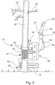
- FIG 3 shows a rough schematic diagram of one example of the tree-handling device 40 used in Figures 1 and 2 seen from the side in the position in which a tree 18 is begun to be felled.
- the tree-handling device 40 can be understood very widely.
- a very typical series of processing operations, which are performed using the tree-handling device 40, is the standing felling of the tree 18, the stripping of the branches 18', and the cutting of the stripped trunk into parts of regular length as the stripping progresses.
- the processing performed by the tree-handling device 40 can also be the individual operations referred to above or various combinations of them.
- It can be, for example, stripping of tree trunks, cutting performed in connection with stripping, and/or collection of one or more ready stripped tree trunks, for example, for the stacking or loading of the trees.
- One or even more trees may be handled at a time, in which case it can be called the bundle handling of trees.
- the tree-handling device 40 shown in Figure 3 can also be called a harvester or processor head.
- the suspension device 52 and operating unit 44 of the tree-handling device 40 are in the felling position.
- the tree-handling device 40 includes its rotation apparatus (not shown), a suspension device 52, and an operating unit 44.
- the tree-handling device 40 is suspended from the boom 43 on the pivot point 45.
- the boom 43 can be part of the crane 32 of a base machine 30, such as a multi-process machine 31 or a special harvester, or the boom of an excavator or other similar moving base.
- the control and pressurized oil of the tree-handling device 40 comes from the base machine 30 in the manner already referred to.
- the tree-handling device 40 To rotate the operating unit 44, the tree-handling device 40 includes an operating device for rotating the operating unit 44 between the felling position and the stripping positions.
- the tree-handling device 40 In Figure 3 , the tree-handling device 40 is in the felling position.
- the operating unit 44 is then mainly vertical.
- the stripping position is achieved when the operating unit 44 is rotated by the operating device by about 90° from the position shown in Figure 3 .
- the operating unit 44 is mainly horizontal, as shown in Figures 1 and 2 .
- the operating device for rotating the operating unit 44 can be, for example, a hydraulic cylinder located in the casing 58, but it can also be some other operating device suitable for the purpose.
- the tree-handling device 40 also includes a cutting device 42.
- the cutting device 42 is a rotating saw-chain saw. It is located at the end of the tree-handling device 40 and thus also of the operating unit 44.
- the felling of the tree 18, i.e. felling cutting can be performed using the cutting device 42 and, in addition, also the cutting of the tree 18 into regular lengths.
- the cutting device 42 also includes a rotating guide bar 11 ( Figures 4a and 4b ), a saw-chain's 10 drive wheel 16 ( Figures 4a and 4b ), by which the saw chain 10 is rotated around the guide bar 11, and guide bar's 11 rotation means for performing sawing. Using the rotation means, the guide bar is pressed, i.e.
- Figure 1 shows the extreme positions of the guide bar 11 and an arrow showing the back-and-forwards rotational movement between them of the guide bar 11.
- the tree-handling device 40 operates by gripping the tree 18 with the gripping means 41 of the operating unit 44.
- An example of the gripping means 41 are the opening and closing grab claws 50.
- the grab claws 50 can also have a blade function for stripping the tree 18 of branches 18'.
- the feed device 47 can also act as the gripping means.
- the feed device 47 can be, for example, rollers, crawler tracks 53, or even a pulsed feed. Instead processing an individual tree 18, the gripping means 41 and/or the feed device 47 can also be used to perform the bundle processing of trees.
- the operating unit 44 is rotated to the horizontal position to strip the tree 18 of branches 18' and cut it into parts of regular length.
- the tree-handling device 40 is moved relative to the tree 18 by the crawler tracks 53 of the feed device 47.
- the tree 18 travels through the operating unit 44.
- the tree 18 can move relatively to the stationary operating unit 44.
- the grab claws 50 are closed they are tightly against the trunk of the tree 18 and at the same time as the tree 18 moves relative to the operating unit 44 the stripping blades in the edges of the grab claws 50 cut the branches 18' off the tree 18.
- the trunk is sawn into a regular-length part with saw chain 10 of the cutting device 42. After this, stripping continues by feeding the tree through the grab claws 50.
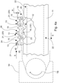
- Figure 4a shows a side view of one example of the saw chain 10 on a guide bar 11. It is also possible to speak of a blade chain, instead of the saw chain 10.
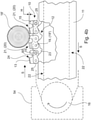
- Figure 4b shows a side view of the same saw chain 10 when the saw chain 10 is in contact with the tree 18 to be cut, when cutting begins.
- the saw chain 10 is thus intended, for example, for the cutting device 42 of the tree-handling device 40 shown in Figure 3 .
- the saw chain 10 includes links 20, which are connected to each other by connector elements 19'.
- the connector elements 19' are rivets 19.
- the links 20 are connected to each other by rivets 19 in such a way that the saw chain 10 is an endless chain loop, which is to be fitted to rotate in a groove 22 arranged in the outer edge of the guide bar 11.
- the links 20 are rotatably pivoted to each other through the rivets 19, to permit the forward and backward movement of the saw chain 10 around the elongated guide bar 11.
- the guide bar 11 is now an elongated blade flange, which can also be called a cutting flange.
- the groove 22 is on the outer edge of the guide bar 11, in the upper edge and correspondingly also in the lower edge.
- the saw chain 10, which is formed as an endless chain loop can be said to have an inner circumference and an outer circumference.
- the chain loop formed by the saw chain 10 is to be arranged to rotate in the groove 22 arranged in the guide bar 11.
- the outer circumference of the saw chain 10 is to be arranged against the tree 18 for its cutting, i.e. sawing.
- the saw chain's 10 cutting elements are on the outer edge of the saw chain 10.
- the saw chain 10 includes tooth links 21 and drive links 12.
- Each tooth link 21 is formed of a cutting tooth 13 protruding sideways from one side of the outer circumference of the saw chain 10, and a side plate 25.
- the cutting tooth 13 for its part includes a cutting edge 24 arranged on the outer circumference of the saw chain 10, and an optional depth-adjustment tooth 15.
- this side is on the side of the outer circumference of the saw chain 10.
- an optional adjustment tooth 15 which can also be called a depth or adjustment tooth. It can be a blunt protrusion made in an as such known manner in the cutting tooth 13.
- the depth-adjustment tooth 15 adjusts, in an as such known manner, the cutting depth H of the cutting edge 24 following the adjustment tooth 15, in the opposite direction to the direction of rotation S of the saw chain 10.
- the adjustment tooth 15 travels on the surface of the tree 18. It determines how deeply H the cutting edge 24 of the cutting tooth 13 following it bites into the tree 18 being sawn.
- the cutting edge 24 includes, following an as such known principle, a cutting corner 26 arranged in its upper corner on the side of the depth-adjustment tooth 15, and the side plate 27 of the tooth link 21 ( Figure 5 ).
- the cutting corner 26 and side plate 27 of the tooth link 21 cut the tree's 18 fibres by cutting the tree 18 by slicing i.e. chipping.
- the cutting tooth 13 also includes a smooth shaping, the cutting corner 29 ( Figure 5 ), arranged in its upper plate 28. This guides the chip cut from the tree 18 away from the sawing groove formed in the tree 18 and at the same time also away from contact with the saw chain 10.
- the cutting corner 29 lifts the cut wood chips up and out of the sawing gap.
- the drive links 12 belonging to the links 20 is to be fitted to the opposite side of the saw chain 10 relative to the side of the adjustment tooth 15 and cutting edge 24 of the cutting tooth 13, in the groove 22 in the guide bar 11. It is then also possible to speak of the inner circumference of the saw chain 10.
- the saw chain 10 is to be fitted into the groove 22 in the guide bar 11, where it circulates the guide bar 11 in the direction of rotation S.
- the drive links 12 include drive tongues 23 on one edge, being the opposite side, i.e. the side of the inner circumference, of the saw chain 10 to the cutting edge 24 and optional depth-adjustment tooth 15.
- the drive tongues 23 fit into the groove 22 in the guide bar 11.
- the drive tongues 23 are shaped to also suit the shape of the outer circumference of the drive and sprockets 16, 17.
- the drive link 12 is attached by these to the preceding and following links 20, in the case of the invention, to the tooth links 21.
- the parts of the tooth link 21, the cutting tooth 13 and side plate 25 of the tooth link 21, lie on each side of the drive link 12 at the rivet holes, to connect the links 20 to each other in a pivoted manner, i.e. rotatably.
- the consecutive tooth links 21 are mainly always connected directly together by a single drive link 12.
- several tooth links 21 can be said to be fitted consecutively to the saw chain 10.
- the saw chain 10 has on one or more sections tooth links 21 immediately on both sides of the drive link 12, in the direction of rotation S of the saw chain 10.
- every second link 20 of the saw chain 10 is a tooth link 21 and every other a drive link 12.
- a tooth link 21 and a drive link 12 are arranged to alternate as links 20 over the entire length of the saw chain 10 and thus also over the entire chain loop.
- the number of tooth links 21 in the saw chain 10 is double that in a saw chain 10' according to the prior art.
- the saw chain 10 has no links at all formed from only side plates 25. This avoids chipping of the tree 18 that takes place too deeply on the cutting edge 24 of the cutting tooth 13. In this way, the cutting tooth 13 cannot have an excessive cutting depth H max .
- consecutive tooth links 21 the cutting teeth 13 are arranged to cut on opposite sides to each other, i.e. to be in opposite directions.
- a cutting teeth 13 can then be said to be alternately right-handed and left-handed.
- the consecutive cutting teeth 13 of the saw chain 10 are arranged to alternate to the right and left sides relative to the plane defined by the guide bar 11.
- the saw chain 10 when link intervals empty of tooth links have been even entirely removed from the saw chain 10, the saw chain 10 can avoid less in the sawing groove the tree 18 being cut, as seen in Figure 7 .
- the tooth links 21 of the saw chain 10 no longer have the possibility to avoid the wood, because in the sawing situation the saw chain 10 is effectively stiffer. Because the tooth links 21 follow each other more densely in the saw chain 10 than in known chains, when the consecutive tooth links 21 are in the sawing groove they oppose this avoidance more effectively. The tooth links 21 are then forced to bite into the wood 18 more effectively and thus sawing too takes place more effectively.
- dynamic width of the saw chain refers to the width of the sawing groove made by the saw chain. Due to the cutting forces, the cutting teeth of the saw chain then seek to avoid the wood in the sawing groove and the width of the sawing groove is not the same as the theoretical width of the saw chain.
- a dynamic width of 8.4 + 0.2 mm was obtained with a new saw chain and correspondingly 7.9 + 0.2 mm with a slightly-used saw chain.
- the tendency of the cutting teeth 13 of the saw chain 10' to avoid the wood 18 being cut was noted to be the greater, the blunter the cutting tooth 13 of the tooth link 21.
- the dynamic width of the saw chain 10 was as much as 9.2 + 0.2 mm.
- the intermediate links 14 formed of only side plates 25 in the saw chain 10' known from the prior art permitted a greater deformation in the saw chain 10'. This results, in known saw chains 10', in the cutting teeth 13 seeking to avoid the wood in the sawing groove and thus the sawing groove becoming narrower.
- the width of the guide bar 11 was 6.3 mm.
- the theoretical sawing groove of the saw chains 10', 10 is 10 + 0.2 mm.
- the saw chain 10, 10' narrows in sawing due to its avoidance property enabled by pivots by about 0.4 mm for every rivet 19 i.e. pivot.
- the saw chain 10 according to the invention narrows about 0.8 mm between consecutive cutting teeth 13.
- a saw chain 10' known from the prior art narrows correspondingly about 1.6 mm due to the four rivets 19, i.e. pivots, between the consecutive cutting teeth 13. It can be said that the tolerance of the connector elements 19' of the saw chain 10 has been arranged to limit the lateral displacement of the tooth links 21.
- the tolerance of the rivets 19 can be, for example, 0 - 0.1 mm.
- the sawing groove can also widen by a corresponding amount for each pivot, so that the saw chain makes the sawing groove too wide.
- the invention also increases the service life of the guide bar 11 and reduces its need for maintenance.
- the cutting teeth 13 cannot in the sawing groove avoid the wood 18 being sawn so much during sawing, the saw chain 10 cannot twist, i.e. tilt, as greatly as in the case of a saw chain 10' according to the prior art.
- the travel of the saw chain 10 in the guide bar 11 is straighter.
- the support of the saw chain 10 takes place, instead of in the groove 22 of the guide bar 11, in the sawing groove using the cutting teeth 13 of the saw chain 10, particularly their sides, against the wood being sawn.
- the support of the saw chain 10 comes more from the consecutive cutting teeth 13 supported in the sawing grove than from the groove 22 in the guide bar 11.
- the guide bar 11 of the tree-handling device 40 according to the invention has in this case a longer life.
- the saw chain 10 according to the invention also remains better in place on top of the guide bar 11.
- the enlarged sawing groove resulting from the saw chain 10 of a tree-handling device 40 permits the narrowing of the physical construction of the saw chain 10.
- the width of the saw chain 10 can be, for example, 10 - 40 %, preferably 15 - 30 % greater than the width of the guide bar 11.
- the width of the saw chain 10 can refer to the distance between the cutting corners 26 of the cutting teeth 13 cutting on opposite sides.
- the saw chain 10 can be implemented narrowed by, for example, parts of 1.6 mm saw chain.
- the invention relates to a tree-handling device 40, of which an example is shown above in Figure 3 .
- the tree-handling device 40 includes gripping means 41 for gripping the tree 18 for cutting, and a cutting device 42.
- the cutting device 42 includes a guide bar 11 equipped with a groove 22.
- a saw chain 10 is arranged to rotate in the groove 22 in order to cut the tree 18.
- the guide bar 11 is arranged to rotate to perform sawing.
- the cutting device 42 also includes a drive wheel 16 ( Figures 4a and 4b ).
- the drive wheel 16 is typically at the end of the guide bar 11, from where the guide bar 11 rotates when cutting the tree 18.
- the saw chain 10 is arranged to run via the drive wheel 16 in order to circulate that around the guide bar 11.
- the inside of the endless chain loop formed by the saw chain 10 is arranged to fit the outer circumference of the drive wheel 16 to transmit power from the drive wheel 16 to the saw chain 10.
- there is shaping in the drive wheel 16 that is compatible with the drive tongues 23 of the drive links 12 of the saw chain 10.
- the drive wheel 16 has a drive device, a saw motor 54, which can be hydraulically operated. It is controlled by valves and their control means.
- the cutting device 42 also includes a guide bar 11 rotation device (not shown).
- the guide bar 11 with its drive wheel 16 is fitted at one end rotatably to the cutting device 42 in order to perform cutting of the tree 18 using the saw chain 10.
- the rotation means can be, for example, a hydraulic cylinder fitted between the guide bar 11 and the structures of the tree-handling device 40.
- the hydraulic cylinder has a pressing movement and a lifting movement. With the pressing movement, the guide bar 11 and the saw chain 10 rotating around it, more generally the cutting saw, is pressed from the guide bar's 11 home position against the tree 18.
- the guide bar 11 with its saw chain 10 turns in the opposite direction compared to the pressing movement. In this way the cutting saw is rotated, i.e. returned to the home position arranged for it in the cutting device 42, ready for the next cutting.
- the control of the cutting device 42 can be implemented using the method according to Finnish patent number 123055 .
- the control operating in the simplest way is based on a throttle installed in the return line of the motor 54 of the drive wheel 16.
- pressure which affects the feed
- the control is obtained with the aid of the throttle for the hydraulic cylinder (rotation device) intended for the feed, i.e. the rotation of the guide bar 11.
- the drive wheel's 16 motor 54 stops the pressure effect ends.
- the same control curve can naturally be implemented electronically and using software.
- the flow data is then collected using a suitable sensor. Using the sensor's data, the software means in turn regulate the pressure of the guide bar's 11 pressing cylinder.
- the saw chain 10 arranged on the guide bar 11 of the cutting device 42 of the tree-handling device 40 includes links 20 connected to each other by connector elements 19', so that the saw chain 10 is an endless chain loop.
- the saw chain 10 includes tooth links 21 and drive links 12.
- Each tooth link 21 includes a cutting tooth 13 protruding sideways on one side of the outer circumference of the saw chain 10.
- In the cutting tooth 13 there is a cutting edge 24 arranged on one side of the saw chain 10, particularly on its outer circumference, and an optional depth-adjustment tooth 15.
- the drive links 12 are fitted into the groove 22 in the guide bar 11 on the opposite side of the saw chain 10, i.e. on the inner circumference of the saw chain 10.
- the consecutive tooth links 21 in the saw chain 10 of the cutting device 42 of the tree-handling device 40 are mainly always joined directly to each other by a single drive link 12, as has been described above in connection with the description of the saw chain 10 itself.
- the weight of the saw chain 10 according to the invention increases by about 10 %.
- the speed of the saw chain 10 can be reduced. A reduction of speed by, for example, one half permits a cutting speed near to the previous one, but the kinetic energy of the saw chain 10 drops by about 70 %. If the speed is reduced by only 30 % of the original speed of the saw chain, in the case of a saw chain 10 according to the invention kinetic energy is created that is only about 60 % relative to a known saw chain 10'.
- the saw chain 10 saws more efficiently at a lower speed, with the toothing according to the invention a greater tensile stress is imposed on the saw chain 10.
- sawing at a speed of 30 m/s requires a power of about 30 kW, i.e. a tensile force of 1000 N acts of the saw chain. This is only about 10 % of the ultimate load of the saw chain, so this force is not decisive.
- the saw chain 10 according to the invention for its part also permits a lightening of the equipment of a multi-process machine. As a principle example can be mention a situation, in which a 70-kW motor can be replaced with a smaller and lighter 40-kW motor. In addition to the smaller engine, the lightening benefit is also accumulated, for example, in the size of the pressure-medium lines and control blocks required.
- the speed of the saw chain when cutting a tree 18 is arranged to be 20 - 35 m/s, 20 - 33 m/s, 20 - 30 m/s, or even more preferably 25 - 33 m/s. 30 m/s can be given as a specific example of the speed.
- the speed of the saw chain 10' can be 40 m/s. Due to the lower speed of the saw chain 10 relative to the prior art, lubricating medium also stays better in the saw chain 10. The lubrication of the sprocket 17 also improves as its speed is lower. All of this increases the life of the guide bar 11, the sprocket 17, and the saw chain 10.
- the length of the guide bar 11 can be, for example, 30 - 100 cm.
- the power of the hydraulic saw motor 54 can be, for example, 20 - 100 kW.
- the power range can be divided into groups.
- the length of the guide bar 11 correlates with the power ranges formed in groups in a set manner. Surplus power can be, for example, 50 %, if more rapid cutting is required.
- One further aspect is also related to an elongated saw-chain blank 100, from which a saw chain 10 is arranged to be formed for the cutting device 42 of the tree-handling device 40.
- the saw-chain blank 100 can be shown by Figure 5 , which shows a top view of it.
- the saw-chain blank 100 includes links 20 connected to each other by connector elements 19'.
- the saw-chain blank 100 includes drive links 12 and tooth links 21.
- Each tooth link 21 includes a cutting tooth 13, protruding sideways to the side of the outer circumference of the saw chain blank 100.
- an optional depth-adjustment tooth 15, and a cutting edge 24 are arranged on one side, particularly on the outer circumference, of the saw-chain blank 100.
- a saw chain 10 can be formed, which is an endless chain loop that can be used in the cutting device 42 of the tree-handling device 40.
- the saw chain 10 is to be arranged to rotate by its drive links 12 in the groove 22 arranged in the guide bar 11 of the cutting device 42 on the inner circumference of the saw chain 10 formed from the saw-chain blank 100.
- the consecutive tooth links 21 in the saw-chain blank 100 are, in the manner described above, mainly always connected directly to each other by a single drive link 12.
- the saw chain 10 is formed from the saw-chain blank 100 by cutting a suitably length saw-chain portion from it for taking into account the length of the guide bar 11, in which the tooth links 21 of the opposite ends cut on opposite sides to each other.
- the opposite ends of the saw-chain blank 100 are then joined together using a connector element 19', in such a way that one drive link 12 comes between the consecutive tooth links 21 at the ends to be joined together.
- an endless chain loop forming an installation-ready saw chain 10 is obtained, which can be installed in the groove 22 arranged for it around the guide bar 11 of the cutting device 42, travelling via the drive wheel 16 belonging to the cutting device 42.
- the invention also further concerns a method for arranging the cutting operation of a tree-handling device 40.
- the tree 18 is gripped before cutting it. Gripping can be performed using the gripping means 41 of the tree-handling device 40, such as, for example grab claws 50.
- the tree 18 is cut by sawing with the saw chain 10.
- the saw chain 10 is circulated by the drive wheel 16 in the groove 22 arranged in the guide bar 11 of the cutting device 42.
- the saw chain 10 includes links 20 joined to each other by connector elements 19', so that the saw chain 10 is an endless chain loop.
- links 20 includes tooth links 21 and drive links 12.
- the tree 18 is cut by sawing, using the tooth links 21.
- Each tooth link 21 includes a cutting tooth 13 protruding sideways from one side of the outer circumference of the saw chain 10.
- the saw chain's 10 drive links 12 are on the opposite side of the saw chain 10, relative to the cutting edge 24 and an optional depth-adjustment tooth 15, in the groove 22 of the guide bar 11.
- the drive links 12 are then on the inner circumference of the saw chain 10.
- the drive links 12 run via the drive wheel 16 belonging to the cutting device 42.
- the travel of the saw chain 10 in the saw groove formed by the saw chain 10 to the tree 18 is evened by the consecutive tooth links 21, which are connected directly to each other by a single drive link 12.
- the travel of the saw chain 10 is then evened by two or more tooth links 21 arranged consecutively in the saw chain 10.
- the saw chain 10 is also rotated during cutting at a speed of 20 - 35 m/s, or even more preferably 25 - 33 m/s.
- the saw chain 10 is rotated around the guide bar 11 by a drive device (drive wheel 16, hydraulic motor 54) and the guide bar 11 is rotated by an operating device against the tree 18 being cut.
- the rotation of the guide bar 11 takes place relative to a pivot point arranged in one end of it.
- the rotation of the guide bar 11 against the tree 18 being cut is controlled on the basis of the speed of the saw chain 10 or a comparable variable.
- the speed of the saw chain 10 according to the invention can vary in different stages of the cutting. At the start and end of the cutting, the saw chain's 10 speed can be higher, and be lower in the middle of the cutting, when the diameter of the object being cut is greatest.
- the speed of the saw chain 10 can be affected and thus sawing accelerated.
- the loading of the guide bar 11 can be correspondingly reduced.
- the loading of the guide bar 11 can also be kept high.
- the saw chain 10 of a tree-handling device 40 according to the invention is also suitable for cutting very small trees.
- the cutting-tooth interval is about 40 mm, whereas in the saw chain 10 according to the invention it is about 20 mm.
- the small branches have less chance of striking the body part of the saw chain 10, i.e. the level of the edge of intermediate links 14 formed of only side plates 25, as these are not in the saw chain 10.
- Such a situation very typically occurs during felling cutting.
- the tree to be felled might be large, there are often branches in its butt area and before the saw chain 10 starts moving a branch or twig can come at an intermediate link in a known saw chain 10' where there is no cutting tooth 13. Due to the great length of the working boom, the driver cannot see precisely the point in the tree where cutting will take place.
- the invention is suitable, for example, for saw chains 10, whose pitch is 10 - 20 mm ( Figure 6 ).
- the pitch is about 10 mm.
- the width of the saw chain 10 can be, for example, 7 + 0.2 mm at the rivets 19 and 5.5 + 0.2 mm at the cutting tooth 13 and the side plate 25.
- the cutting tooth 13 too, especially its upper plate 28, can be narrowed.
- the cutting tooth 13 can be narrowed starting from its cutting corner 26 to the rear edge 48 of the trailing edge of the upper plate 28. This narrows the width of the saw chain 10 compared to a known chain.
- the bite of the cutting tooth 13 can also be reduced.
- the bite can be reduced compared to saw chains 10' according to the prior art, in which the angle between the surface of the upper plate 28 of the cutting tooth 13 and the horizontal plane is, for example, about 9 degrees.
- this angle can be surprisingly substantially smaller than in the known chain.
- An example of this angle is 0.5 - 7 degrees, 0.5 - 6 degrees, particularly 0.7 - 6 degrees, 0.7 - 5 degrees, and further, as various specific examples, 7 degrees, 6 degrees, 5 degrees, 4 degrees, 3 degrees, 2 degrees, 1 degree, preferably 1 - 5 degrees.
- the small bite angle gives plenty of space for the chips created during sawing, which becomes less thick than in the prior art, due to the smaller bite angle.
- the only point in the saw chain 10 deviating essentially from a mainly straight line is between the depth-adjustment tooth 15 and the cutting edge 24 of the cutting tooth 13.
- the durability of the saw chain 10 thus improves and thus the thickness of the windshield 38 of the multi-process machine 31 can be, for example, only 5 - 15 mm, because the risk of the saw chain 10 breaking is reduced.
- Figure 8 shows yet another example of the saw chain 10. It demonstrates that the tooth links 21 can even lack the depth-adjustment tooth 15, which is included in the examples described above.
- the depth H s of the space 59 between the consecutive cutting teeth 13 can correspond mainly to the height H c of the cutting tooth 13 over the whole space from the rear edge 48 of the preceding cutting tooth 13 to the cutting edge 24 of the following cutting tooth 13.
- the space 59 between the consecutive cutting teeth 13 can be at least half free of structures in the direction of the height H c of the cutting tooth 13.
- the height of the depth-adjustment tooth 15, or the corresponding formation 15' at the same location is less than 50 % of the height H c of the cutting tooth 13.
- the height of the depth-adjustment tooth 15 or the formation 15' which is, for example, at a corresponding location to it, is less than 20 % of the height H c of the cutting tooth 13, but, however, under 60 % of the height H c of the cutting tooth 13.
- the height of the depth-adjustment tooth 15 can be 1 - 60 % of the height H c of the cutting tooth 13.
- the height H s of the space 59 (determined by the outer edge of the formation 15') between the consecutive cutting teeth 13 is more than 40 % of the height H c of the cutting tooth 13.
- the height H c of the cutting tooth 13 is the distance from the base of the saw chain 10, i.e. from the base 60 of the cutting tooth 13 to the cutting edge 24 of the cutting tooth 13.
- the base 60 of the cutting tooth 13 corresponds mainly to the outer edge of the side plate 25.
- the depth H s of the space 59 is the (vertical) distance from the upper edge of the formation 15' to the cutting edge 24 of the cutting tooth 13.
- the cutting depth H of the cutting teeth 13 can be maintained by the cutting teeth 13 themselves.
- the reduced bite angle also assists in this, H max being smaller due to it. This simplifies the construction of the saw chain 10 and also facilitates its maintenance (for example, there is no need to adjust the height of the depth-adjustment tooth).
- the invention has been tried in harvesters manufactured bv Kone Ketonen Oy.
- the chains were manufactured from "STIHL ® motoketju” chains (groove widths 1.6 mm and 2.0 mm) marketed by Uittokalusto Oy (FI).
- the STIHL ® chains were disassembled into components and reassembled again without the intermediate links between the tooth links 21.
Landscapes
- Life Sciences & Earth Sciences (AREA)
- Forests & Forestry (AREA)
- Engineering & Computer Science (AREA)
- Mechanical Engineering (AREA)
- Wood Science & Technology (AREA)
- Biodiversity & Conservation Biology (AREA)
- Ecology (AREA)
- Environmental Sciences (AREA)
- Sawing (AREA)
Priority Applications (1)
| Application Number | Priority Date | Filing Date | Title |
|---|---|---|---|
| PL16186325T PL3138673T3 (pl) | 2015-09-03 | 2016-08-30 | Urządzenie do obróbki drzewa, maszyna wieloprocesowa, sposób organizowania operacji cięcia w urządzeniu do obróbki drzewa |
Applications Claiming Priority (5)
| Application Number | Priority Date | Filing Date | Title |
|---|---|---|---|
| FI20150251 | 2015-09-03 | ||
| FI20155693A FI126453B (fi) | 2015-09-03 | 2015-09-30 | Puunkäsittelylaite ja menetelmä puunkäsittelylaitteen katkaisutoiminnon järjestämiseksi |
| FI20155751 | 2015-10-22 | ||
| FI20165585 | 2016-07-13 | ||
| FIU20164171U FI11459U1 (fi) | 2015-09-03 | 2016-08-24 | Klapikone |
Publications (2)
| Publication Number | Publication Date |
|---|---|
| EP3138673A1 EP3138673A1 (en) | 2017-03-08 |
| EP3138673B1 true EP3138673B1 (en) | 2022-01-19 |
Family
ID=78829234
Family Applications (1)
| Application Number | Title | Priority Date | Filing Date |
|---|---|---|---|
| EP16186325.3A Active EP3138673B1 (en) | 2015-09-03 | 2016-08-30 | A tree-handling device, a multi-process machine, a method for arranging the cutting operation of a tree-handling device |
Country Status (3)
| Country | Link |
|---|---|
| EP (1) | EP3138673B1 (pl) |
| HU (1) | HUE058147T2 (pl) |
| PL (1) | PL3138673T3 (pl) |
Families Citing this family (1)
| Publication number | Priority date | Publication date | Assignee | Title |
|---|---|---|---|---|
| US20190210242A1 (en) * | 2016-08-24 | 2019-07-11 | Lauri Ketonen | Saw chain for the cutting device of a tree-handling device, a tree-handling device, a saw-chain blank, and a method for arranging the cutting operation of a tree-handling device |
Family Cites Families (7)
| Publication number | Priority date | Publication date | Assignee | Title |
|---|---|---|---|---|
| US2515550A (en) * | 1947-09-17 | 1950-07-18 | Joseph J Ciba | Chain saw |
| CA949853A (en) * | 1973-02-26 | 1974-06-25 | Michael Dika | Tree felling apparatus |
| DE7528022U (de) * | 1974-11-11 | 1976-05-20 | Omark Canada Ltd., North Guelph, Ontario (Kanada) | Saegekette |
| CN85107323A (zh) * | 1985-09-21 | 1986-10-29 | 福建省福州市东方红链条厂 | 锯链 |
| FI119274B (fi) * | 2005-12-02 | 2008-09-30 | John Deere Forestry Oy | Ohjauskytkentä karsinta- ja katkaisulaitteiston syöttöelimien syöttönopeuden muuttamiseksi |
| FI20110139A0 (fi) | 2011-04-20 | 2011-04-20 | Lauri Kalervo Ketonen | Katkaisusahan ohjaus monitoimikoneessa |
| CN204540199U (zh) * | 2015-04-28 | 2015-08-12 | 国家林业局哈尔滨林业机械研究所 | 一种伐木清林作业机 |
-
2016
- 2016-08-30 PL PL16186325T patent/PL3138673T3/pl unknown
- 2016-08-30 EP EP16186325.3A patent/EP3138673B1/en active Active
- 2016-08-30 HU HUE16186325A patent/HUE058147T2/hu unknown
Also Published As
| Publication number | Publication date |
|---|---|
| EP3138673A1 (en) | 2017-03-08 |
| HUE058147T2 (hu) | 2022-07-28 |
| PL3138673T3 (pl) | 2022-04-19 |
Similar Documents
| Publication | Publication Date | Title |
|---|---|---|
| US20170066155A1 (en) | Cutting device and a method of cutting with a cutting device | |
| DE60115635T2 (de) | Verfahren und anordnung zur regelung der zufuhrgeschwindigkeit einer kappsäge | |
| CA2697300C (en) | Aggregate cutting saw chain | |
| US20220219350A1 (en) | Saw chain link with one or more oversized rivet holes | |
| EP3138673B1 (en) | A tree-handling device, a multi-process machine, a method for arranging the cutting operation of a tree-handling device | |
| EP1392102B1 (de) | Entastungsvorrichtung zum entfernen der äste von lebenden bäumen | |
| CN101367216A (zh) | 木材加工机械送料机构及其操作方法 | |
| US20190210242A1 (en) | Saw chain for the cutting device of a tree-handling device, a tree-handling device, a saw-chain blank, and a method for arranging the cutting operation of a tree-handling device | |
| US4462439A (en) | Chain saw with single-wedge, chain-protecting chain support | |
| FI126453B (fi) | Puunkäsittelylaite ja menetelmä puunkäsittelylaitteen katkaisutoiminnon järjestämiseksi | |
| US4513799A (en) | Method of cutting substantially horizontal cantilevered objects such as logs, and apparatus for carrying out the method | |
| CN201023265Y (zh) | 联合伐木工作头 | |
| SE1000064A1 (sv) | Anordning och metod för fällning och kapning av trädstammar | |
| JP7584362B2 (ja) | 樹木処理装置 | |
| CN201217234Y (zh) | 木材加工机械送料机构 | |
| DE202016104676U1 (de) | Sägespaltautomat | |
| US20190159410A1 (en) | Improvements in Tree Processing Systems | |
| JP2019528199A (ja) | 樹木伐採処理装置の切断装置用ソーチェーン、樹木伐採処理装置、ソーチェーンブランク、および樹木伐採処理装置の切断動作方法 | |
| JP4339794B2 (ja) | 木材伐採機の送り装置 | |
| JP7755510B2 (ja) | 作業機械 | |
| EP0232271A1 (en) | Method for guiding saw blades | |
| RU2619285C2 (ru) | Устройство, связанное с подающим роликом | |
| US781700A (en) | Drag-saw machine. | |
| RU2320477C2 (ru) | Ленточнопильный станок | |
| FI13232Y1 (fi) | Taimikonhoitolaitteisto pienmetsäkoneeseen |
Legal Events
| Date | Code | Title | Description |
|---|---|---|---|
| PUAI | Public reference made under article 153(3) epc to a published international application that has entered the european phase |
Free format text: ORIGINAL CODE: 0009012 |
|
| STAA | Information on the status of an ep patent application or granted ep patent |
Free format text: STATUS: THE APPLICATION HAS BEEN PUBLISHED |
|
| AK | Designated contracting states |
Kind code of ref document: A1 Designated state(s): AL AT BE BG CH CY CZ DE DK EE ES FI FR GB GR HR HU IE IS IT LI LT LU LV MC MK MT NL NO PL PT RO RS SE SI SK SM TR |
|
| AX | Request for extension of the european patent |
Extension state: BA ME |
|
| STAA | Information on the status of an ep patent application or granted ep patent |
Free format text: STATUS: REQUEST FOR EXAMINATION WAS MADE |
|
| 17P | Request for examination filed |
Effective date: 20170907 |
|
| RBV | Designated contracting states (corrected) |
Designated state(s): AL AT BE BG CH CY CZ DE DK EE ES FI FR GB GR HR HU IE IS IT LI LT LU LV MC MK MT NL NO PL PT RO RS SE SI SK SM TR |
|
| GRAP | Despatch of communication of intention to grant a patent |
Free format text: ORIGINAL CODE: EPIDOSNIGR1 |
|
| STAA | Information on the status of an ep patent application or granted ep patent |
Free format text: STATUS: GRANT OF PATENT IS INTENDED |
|
| RIC1 | Information provided on ipc code assigned before grant |
Ipc: B27B 33/14 20060101AFI20210219BHEP Ipc: A01G 23/091 20060101ALI20210219BHEP |
|
| INTG | Intention to grant announced |
Effective date: 20210323 |
|
| GRAJ | Information related to disapproval of communication of intention to grant by the applicant or resumption of examination proceedings by the epo deleted |
Free format text: ORIGINAL CODE: EPIDOSDIGR1 |
|
| STAA | Information on the status of an ep patent application or granted ep patent |
Free format text: STATUS: REQUEST FOR EXAMINATION WAS MADE |
|
| GRAP | Despatch of communication of intention to grant a patent |
Free format text: ORIGINAL CODE: EPIDOSNIGR1 |
|
| STAA | Information on the status of an ep patent application or granted ep patent |
Free format text: STATUS: GRANT OF PATENT IS INTENDED |
|
| INTC | Intention to grant announced (deleted) | ||
| INTG | Intention to grant announced |
Effective date: 20210811 |
|
| GRAS | Grant fee paid |
Free format text: ORIGINAL CODE: EPIDOSNIGR3 |
|
| GRAA | (expected) grant |
Free format text: ORIGINAL CODE: 0009210 |
|
| STAA | Information on the status of an ep patent application or granted ep patent |
Free format text: STATUS: THE PATENT HAS BEEN GRANTED |
|
| AK | Designated contracting states |
Kind code of ref document: B1 Designated state(s): AL AT BE BG CH CY CZ DE DK EE ES FI FR GB GR HR HU IE IS IT LI LT LU LV MC MK MT NL NO PL PT RO RS SE SI SK SM TR |
|
| REG | Reference to a national code |
Ref country code: GB Ref legal event code: FG4D |
|
| REG | Reference to a national code |
Ref country code: CH Ref legal event code: EP |
|
| REG | Reference to a national code |
Ref country code: DE Ref legal event code: R096 Ref document number: 602016068440 Country of ref document: DE |
|
| REG | Reference to a national code |
Ref country code: AT Ref legal event code: REF Ref document number: 1463529 Country of ref document: AT Kind code of ref document: T Effective date: 20220215 |
|
| REG | Reference to a national code |
Ref country code: IE Ref legal event code: FG4D |
|
| REG | Reference to a national code |
Ref country code: FI Ref legal event code: FGE |
|
| REG | Reference to a national code |
Ref country code: SE Ref legal event code: TRGR |
|
| REG | Reference to a national code |
Ref country code: LT Ref legal event code: MG9D |
|
| REG | Reference to a national code |
Ref country code: EE Ref legal event code: FG4A Ref document number: E022111 Country of ref document: EE Effective date: 20220321 |
|
| REG | Reference to a national code |
Ref country code: NL Ref legal event code: MP Effective date: 20220119 |
|
| PG25 | Lapsed in a contracting state [announced via postgrant information from national office to epo] |
Ref country code: NL Free format text: LAPSE BECAUSE OF FAILURE TO SUBMIT A TRANSLATION OF THE DESCRIPTION OR TO PAY THE FEE WITHIN THE PRESCRIBED TIME-LIMIT Effective date: 20220119 |
|
| REG | Reference to a national code |
Ref country code: HU Ref legal event code: AG4A Ref document number: E058147 Country of ref document: HU |
|
| PG25 | Lapsed in a contracting state [announced via postgrant information from national office to epo] |
Ref country code: RS Free format text: LAPSE BECAUSE OF FAILURE TO SUBMIT A TRANSLATION OF THE DESCRIPTION OR TO PAY THE FEE WITHIN THE PRESCRIBED TIME-LIMIT Effective date: 20220119 Ref country code: PT Free format text: LAPSE BECAUSE OF FAILURE TO SUBMIT A TRANSLATION OF THE DESCRIPTION OR TO PAY THE FEE WITHIN THE PRESCRIBED TIME-LIMIT Effective date: 20220519 Ref country code: NO Free format text: LAPSE BECAUSE OF FAILURE TO SUBMIT A TRANSLATION OF THE DESCRIPTION OR TO PAY THE FEE WITHIN THE PRESCRIBED TIME-LIMIT Effective date: 20220419 Ref country code: LT Free format text: LAPSE BECAUSE OF FAILURE TO SUBMIT A TRANSLATION OF THE DESCRIPTION OR TO PAY THE FEE WITHIN THE PRESCRIBED TIME-LIMIT Effective date: 20220119 Ref country code: HR Free format text: LAPSE BECAUSE OF FAILURE TO SUBMIT A TRANSLATION OF THE DESCRIPTION OR TO PAY THE FEE WITHIN THE PRESCRIBED TIME-LIMIT Effective date: 20220119 Ref country code: ES Free format text: LAPSE BECAUSE OF FAILURE TO SUBMIT A TRANSLATION OF THE DESCRIPTION OR TO PAY THE FEE WITHIN THE PRESCRIBED TIME-LIMIT Effective date: 20220119 Ref country code: BG Free format text: LAPSE BECAUSE OF FAILURE TO SUBMIT A TRANSLATION OF THE DESCRIPTION OR TO PAY THE FEE WITHIN THE PRESCRIBED TIME-LIMIT Effective date: 20220419 |
|
| PG25 | Lapsed in a contracting state [announced via postgrant information from national office to epo] |
Ref country code: LV Free format text: LAPSE BECAUSE OF FAILURE TO SUBMIT A TRANSLATION OF THE DESCRIPTION OR TO PAY THE FEE WITHIN THE PRESCRIBED TIME-LIMIT Effective date: 20220119 Ref country code: GR Free format text: LAPSE BECAUSE OF FAILURE TO SUBMIT A TRANSLATION OF THE DESCRIPTION OR TO PAY THE FEE WITHIN THE PRESCRIBED TIME-LIMIT Effective date: 20220420 |
|
| PG25 | Lapsed in a contracting state [announced via postgrant information from national office to epo] |
Ref country code: IS Free format text: LAPSE BECAUSE OF FAILURE TO SUBMIT A TRANSLATION OF THE DESCRIPTION OR TO PAY THE FEE WITHIN THE PRESCRIBED TIME-LIMIT Effective date: 20220519 |
|
| REG | Reference to a national code |
Ref country code: DE Ref legal event code: R097 Ref document number: 602016068440 Country of ref document: DE |
|
| PG25 | Lapsed in a contracting state [announced via postgrant information from national office to epo] |
Ref country code: SM Free format text: LAPSE BECAUSE OF FAILURE TO SUBMIT A TRANSLATION OF THE DESCRIPTION OR TO PAY THE FEE WITHIN THE PRESCRIBED TIME-LIMIT Effective date: 20220119 Ref country code: SK Free format text: LAPSE BECAUSE OF FAILURE TO SUBMIT A TRANSLATION OF THE DESCRIPTION OR TO PAY THE FEE WITHIN THE PRESCRIBED TIME-LIMIT Effective date: 20220119 Ref country code: RO Free format text: LAPSE BECAUSE OF FAILURE TO SUBMIT A TRANSLATION OF THE DESCRIPTION OR TO PAY THE FEE WITHIN THE PRESCRIBED TIME-LIMIT Effective date: 20220119 Ref country code: DK Free format text: LAPSE BECAUSE OF FAILURE TO SUBMIT A TRANSLATION OF THE DESCRIPTION OR TO PAY THE FEE WITHIN THE PRESCRIBED TIME-LIMIT Effective date: 20220119 |
|
| PGFP | Annual fee paid to national office [announced via postgrant information from national office to epo] |
Ref country code: SE Payment date: 20220819 Year of fee payment: 7 Ref country code: FI Payment date: 20220819 Year of fee payment: 7 Ref country code: AT Payment date: 20220822 Year of fee payment: 7 |
|
| PLBE | No opposition filed within time limit |
Free format text: ORIGINAL CODE: 0009261 |
|
| STAA | Information on the status of an ep patent application or granted ep patent |
Free format text: STATUS: NO OPPOSITION FILED WITHIN TIME LIMIT |
|
| PG25 | Lapsed in a contracting state [announced via postgrant information from national office to epo] |
Ref country code: AL Free format text: LAPSE BECAUSE OF FAILURE TO SUBMIT A TRANSLATION OF THE DESCRIPTION OR TO PAY THE FEE WITHIN THE PRESCRIBED TIME-LIMIT Effective date: 20220119 |
|
| 26N | No opposition filed |
Effective date: 20221020 |
|
| PGFP | Annual fee paid to national office [announced via postgrant information from national office to epo] |
Ref country code: CH Payment date: 20220824 Year of fee payment: 7 |
|
| PG25 | Lapsed in a contracting state [announced via postgrant information from national office to epo] |
Ref country code: SI Free format text: LAPSE BECAUSE OF FAILURE TO SUBMIT A TRANSLATION OF THE DESCRIPTION OR TO PAY THE FEE WITHIN THE PRESCRIBED TIME-LIMIT Effective date: 20220119 |
|
| REG | Reference to a national code |
Ref country code: EE Ref legal event code: MM4A Ref document number: E022111 Country of ref document: EE Effective date: 20220831 |
|
| PG25 | Lapsed in a contracting state [announced via postgrant information from national office to epo] |
Ref country code: MC Free format text: LAPSE BECAUSE OF FAILURE TO SUBMIT A TRANSLATION OF THE DESCRIPTION OR TO PAY THE FEE WITHIN THE PRESCRIBED TIME-LIMIT Effective date: 20220119 |
|
| GBPC | Gb: european patent ceased through non-payment of renewal fee |
Effective date: 20220830 |
|
| PG25 | Lapsed in a contracting state [announced via postgrant information from national office to epo] |
Ref country code: LU Free format text: LAPSE BECAUSE OF NON-PAYMENT OF DUE FEES Effective date: 20220830 Ref country code: CZ Free format text: LAPSE BECAUSE OF NON-PAYMENT OF DUE FEES Effective date: 20220830 |
|
| REG | Reference to a national code |
Ref country code: BE Ref legal event code: MM Effective date: 20220831 |
|
| PG25 | Lapsed in a contracting state [announced via postgrant information from national office to epo] |
Ref country code: HU Free format text: LAPSE BECAUSE OF NON-PAYMENT OF DUE FEES Effective date: 20220831 Ref country code: EE Free format text: LAPSE BECAUSE OF NON-PAYMENT OF DUE FEES Effective date: 20220831 |
|
| REG | Reference to a national code |
Ref country code: AT Ref legal event code: UEP Ref document number: 1463529 Country of ref document: AT Kind code of ref document: T Effective date: 20220119 |
|
| P01 | Opt-out of the competence of the unified patent court (upc) registered |
Effective date: 20230614 |
|
| PG25 | Lapsed in a contracting state [announced via postgrant information from national office to epo] |
Ref country code: IT Free format text: LAPSE BECAUSE OF NON-PAYMENT OF DUE FEES Effective date: 20220830 Ref country code: IE Free format text: LAPSE BECAUSE OF NON-PAYMENT OF DUE FEES Effective date: 20220830 Ref country code: FR Free format text: LAPSE BECAUSE OF NON-PAYMENT OF DUE FEES Effective date: 20220831 |
|
| PG25 | Lapsed in a contracting state [announced via postgrant information from national office to epo] |
Ref country code: BE Free format text: LAPSE BECAUSE OF NON-PAYMENT OF DUE FEES Effective date: 20220831 |
|
| PG25 | Lapsed in a contracting state [announced via postgrant information from national office to epo] |
Ref country code: GB Free format text: LAPSE BECAUSE OF NON-PAYMENT OF DUE FEES Effective date: 20220830 |
|
| REG | Reference to a national code |
Ref country code: CH Ref legal event code: PL |
|
| REG | Reference to a national code |
Ref country code: AT Ref legal event code: MM01 Ref document number: 1463529 Country of ref document: AT Kind code of ref document: T Effective date: 20230830 |
|
| PG25 | Lapsed in a contracting state [announced via postgrant information from national office to epo] |
Ref country code: AT Free format text: LAPSE BECAUSE OF NON-PAYMENT OF DUE FEES Effective date: 20230830 |
|
| PG25 | Lapsed in a contracting state [announced via postgrant information from national office to epo] |
Ref country code: FI Free format text: LAPSE BECAUSE OF NON-PAYMENT OF DUE FEES Effective date: 20230830 Ref country code: CY Free format text: LAPSE BECAUSE OF FAILURE TO SUBMIT A TRANSLATION OF THE DESCRIPTION OR TO PAY THE FEE WITHIN THE PRESCRIBED TIME-LIMIT Effective date: 20220119 Ref country code: AT Free format text: LAPSE BECAUSE OF NON-PAYMENT OF DUE FEES Effective date: 20230830 Ref country code: CH Free format text: LAPSE BECAUSE OF NON-PAYMENT OF DUE FEES Effective date: 20230831 |
|
| PG25 | Lapsed in a contracting state [announced via postgrant information from national office to epo] |
Ref country code: PL Free format text: LAPSE BECAUSE OF NON-PAYMENT OF DUE FEES Effective date: 20220830 Ref country code: MK Free format text: LAPSE BECAUSE OF FAILURE TO SUBMIT A TRANSLATION OF THE DESCRIPTION OR TO PAY THE FEE WITHIN THE PRESCRIBED TIME-LIMIT Effective date: 20220119 Ref country code: SE Free format text: LAPSE BECAUSE OF NON-PAYMENT OF DUE FEES Effective date: 20230831 |
|
| PG25 | Lapsed in a contracting state [announced via postgrant information from national office to epo] |
Ref country code: TR Free format text: LAPSE BECAUSE OF NON-PAYMENT OF DUE FEES Effective date: 20220830 Ref country code: MT Free format text: LAPSE BECAUSE OF FAILURE TO SUBMIT A TRANSLATION OF THE DESCRIPTION OR TO PAY THE FEE WITHIN THE PRESCRIBED TIME-LIMIT Effective date: 20220119 |
|
| PGFP | Annual fee paid to national office [announced via postgrant information from national office to epo] |
Ref country code: DE Payment date: 20250820 Year of fee payment: 10 |