EP3138378B1 - Vorrichtung zum mähen, vertikutieren und/oder aufsammeln - Google Patents
Vorrichtung zum mähen, vertikutieren und/oder aufsammeln Download PDFInfo
- Publication number
- EP3138378B1 EP3138378B1 EP16401052.2A EP16401052A EP3138378B1 EP 3138378 B1 EP3138378 B1 EP 3138378B1 EP 16401052 A EP16401052 A EP 16401052A EP 3138378 B1 EP3138378 B1 EP 3138378B1
- Authority
- EP
- European Patent Office
- Prior art keywords
- collecting container
- cover
- covering hood
- opening
- emptying
- Prior art date
- Legal status (The legal status is an assumption and is not a legal conclusion. Google has not performed a legal analysis and makes no representation as to the accuracy of the status listed.)
- Active
Links
Images

Classifications
-
- A—HUMAN NECESSITIES
- A01—AGRICULTURE; FORESTRY; ANIMAL HUSBANDRY; HUNTING; TRAPPING; FISHING
- A01D—HARVESTING; MOWING
- A01D43/00—Mowers combined with apparatus performing additional operations while mowing
- A01D43/06—Mowers combined with apparatus performing additional operations while mowing with means for collecting, gathering or loading mown material
- A01D43/063—Mowers combined with apparatus performing additional operations while mowing with means for collecting, gathering or loading mown material in or into a container carried by the mower; Containers therefor
-
- A—HUMAN NECESSITIES
- A01—AGRICULTURE; FORESTRY; ANIMAL HUSBANDRY; HUNTING; TRAPPING; FISHING
- A01B—SOIL WORKING IN AGRICULTURE OR FORESTRY; PARTS, DETAILS, OR ACCESSORIES OF AGRICULTURAL MACHINES OR IMPLEMENTS, IN GENERAL
- A01B45/00—Machines for treating meadows or lawns, e.g. for sports grounds
- A01B45/02—Machines for treating meadows or lawns, e.g. for sports grounds for aerating
- A01B45/026—Scarifiers comprising a knife reel actively driven around a substantially horizontal shaft
Definitions
- the invention relates to a device for mowing, scarifying and / or collecting according to the preamble of claim 1.
- the cover is divided into two halves, of which one half of the cover on one side of the opening of the collecting container and the other half of the cover on the opposite side of the opening of the collecting container are pivotally articulated.
- the respective halves of the cover are arranged freely pivotable on the collecting container.
- the respective halves of the cover pivot uncontrolled when bringing the collecting container in the emptying position and the backward pivoting of the collecting container in the collecting position. This is very stressful for the joints and components of the collecting container and the halves of the cover, so that it comes to damage to these components. In addition, a high level of noise is created.
- the collected by the device substances are collected in a collection container.
- the collecting container is mounted on a frame of the device by means of a lifting and / or tilting device which rotates and empties the collecting container for emptying via this device in a discharge position.
- the emptying takes place via an emptying opening arranged in the upper area of the collecting container.
- the discharge opening is covered in working position by a means of a hinge device to the collecting pivotally arranged cover.
- a resilient element which is designed as a gas spring, arranged.
- This gas spring brings the cover on the one hand when swiveling the container automatically in the open position and on the other hand when returning the container in working position automatically and jerky in the closed position. Closing the discharge opening by the cover by means of here accordingly arranged gas spring is very noisy and noisy. This is undesirable in many cases, once in terms of noise and on the other hand because of the high wear.
- the invention is based on the object to achieve a controlled pivoting of the cover for the defined opening and a gentle and quiet closing of the discharge opening through the cover.
- this resilient teeing element at the beginning of the closing operation of the discharge opening through the cover ensures that the cover is pressed immediately at the beginning of bringing the collecting container from the emptying position to the working position in an unfavorable position in the direction of the closed position. This is achieved in a gentle manner in that the resilient stop element abuts the cover at the beginning of the closing operation of the discharge opening through the cover and presses the cover in the direction of covering the cover.
- the resilient element is designed such that it does not actively support the opening or closing of the cover when opening or when closing the discharge opening by the cover.
- the resilient stop element may have a compression spring.
- the resilient element is formed between collecting container and cover as a gas spring and / or gas spring.
- Device for mowing, scarifying and / or collecting grass, leaves, dirt or other materials obtained in the landscape care in a collection container is formed in the embodiment as a drawn mower and Vertikutiermaschine.
- This machine has the frame 1, which is located on the rear wheels 2 on the ground and on the arranged in the front region of the frame 1 drawbar 3, to a not shown Tractor is docked, supports.
- a mowing or Vertikutier coupled 4 is arranged in a known manner.
- This device 4 is driven by the PTO of the towing vehicle via the hinge shaft 5 in a known manner.
- the collecting container 6 is arranged on the frame by means of a lifting and tilting device 7.
- This lifting and tilting device 7 has a hydraulic cylinder 8 on each side of the collecting container 6.
- the collecting container 6 has according to its working position FIG. 1 in its upper region, the discharge opening 9.
- the discharge opening 9 is covered in its rear region 10 by the cover 11 and in its front region 12 by a cover plate 13.
- the cover plate 13 is pivotally mounted in the front region by means of joints 14 to the collecting container 5.
- the cover 11 is pivotally mounted in its rear region at the rear region of the collecting container 6 by means of joints 15.
- the cover plate 13 and the cover 11 cover the discharge opening 9 in the working position of the collecting container 6.
- the cover 11 also serves as a transfer flap, for example, if the material must be transferred without loss in a transport container, not shown.
- the hinge device 15, by means of which the cover 11 is arranged on the collecting container 6, is located between the upper - rear region of the discharge opening 9 and the rear region of the cover 11.
- Between the collecting container 6 and the cover 11 is at least one as a gas spring or gas spring trained resilient element 16 is arranged.
- the resilient member 16 is arranged so that the resilient member 16 during the movement of the collecting container 6 from the emptying position into the working position, the cover 11 during the Closing operation of the discharge opening 9 decelerates through the cover 11.
- a controlled pivoting of the cover 11 is achieved with a gentle and quiet closing of the discharge opening 9 through the cover 11. Due to the resilient element 16, the cover 11 during pivoting of the collecting container 6 in the working position in a gentle manner in their covering position Fig. 1 pivoted, so that very quiet and controlled the discharge opening 9 is closed by the cover 11.
- This resilient stop member 17 defines the opening position of the cover 11 and limits the opening of the cover 11, as the Fig. 3 - 6 demonstrate.
- the resilient stop member 17 in the final phase of the opening process the cover 11 in addition to decelerate gently in its final position.
- the end opening position for the cover 11 is set during the emptying of the collecting container 6 in a gentle manner.
- the resilient element 16 is designed and arranged such that it does not actively support the opening or closing of the cover hood when opening or when closing the discharge opening 9 through the cover 11.
- the cover 11 When pivoting the cover 11 in the emptying position of the collecting container and the cover according to Fig.2 supports the gas spring 16, the opening of the cover not, but the cover 11 passes due to their arrangement and their weight in the illustrated open position.
- the cover When the container 6 is empty and turned back to the working position, as in Fig.3-6 shown, the cover is forced if necessary by the resilient stop member 17 toward the closed position and then pivots due to their weight in a braked manner by the gas spring in its closed position according to Fig.1 back. Since the cover slowly pivots back into the closed position due to the gas spring 16, the cover 11 closes controlled, noiseless and gentle.
- the stop element 17 is designed as a compression spring.
- the resilient stop member 17 ensures at the beginning of the closing operation of the discharge opening 9 through the cover 11 for when the collecting container 9 and the cover 11 in the in Fig.3-6 shown position of the collecting container 6 and the cover 11 is that the cover 11 immediately at the beginning of bringing the collecting container from the emptying position to the working position in unfavorable position, as shown in the above figure, in the direction of closing position accordingly Fig.1 is pressed.
- This is achieved in a gentle manner in that the resilient stop member 17 abuts the cover 11 at the beginning of the closing operation of the discharge opening 9 through the cover 11 and the cover 11 in the direction of covering the cover 11 presses.
Landscapes
- Life Sciences & Earth Sciences (AREA)
- Environmental Sciences (AREA)
- Harvester Elements (AREA)
Description
- Die Erfindung betrifft eine Vorrichtung zum Mähen, Vertikutieren und/oder Aufsammeln gemäß des Oberbegriffes des Patentanspruches 1.
- Durch die
EP 1 557 081 A1 ist eine derartige Vorrichtung bekannt. Bei dieser Vorrichtung ist die Abdeckhaube in zwei Hälften geteilt, wovon die eine Hälfte der Abdeckhaube an der einen Seite der Öffnung des Sammelbehälters und die andere Hälfte der Abdeckhaube an der gegenüberliegenden Seite der Öffnung des Sammelbehälters schwenkbar angelenkt sind. Die jeweiligen Hälften der Abdeckhaube sind frei schwenkbar an dem Sammelbehälter angeordnet. Hierdurch verschwenken die jeweiligen Hälften der Abdeckhaube beim Bringen des Sammelbehälters in die Entleerposition und beim Zurückverschwenken des Sammelbehälters in die Sammelposition unkontrolliert. Dieses ist sehr belastend für die Gelenke und Bauteile des Sammelbehälter und der Hälften der Abdeckhaube, so dass es zu Beschädigungen an diesen Bauteilen kommt. Darüber hinaus entsteht eine hohe Geräuschentwicklung. - Eine weitere Vorrichtung zum Mähen, Vertikutieren und/oder Aufsammeln ist in der
EP 0 676 128 A1 beschrieben. Die von der Vorrichtung aufgesammelten Stoffe werden in einen Sammelbehälter gesammelt. Der Sammelbehälter ist an einem Rahmen der Vorrichtung mittels einer Hebe- und/oder Kippeinrichtung montiert, die den Sammelbehälter zum Entleeren über diese Vorrichtung in eine Entleerungsstellung dreht und entleert. Die Entleerung erfolgt über eine in dem oberen Bereich des Sammelbehälters angeordnete Entleerungsöffnung. Die Entleerungsöffnung ist in Arbeitsstellung durch eine mittels einer Gelenkvorrichtung an den Sammelbehälter verschwenkbar angeordnete Abdeckhaube abgedeckt. Bei dieser bekannten Vorrichtung ist zwischen dem Sammelbehälter und der Abdeckhaube ein federndes Element, welches als Gasdruckfeder ausgebildet ist, angeordnet. Diese Gasdruckfeder bringt die Abdeckhaube einerseits beim Schwenken des Behälters automatisch in Öffnungsstellung und andererseits beim Rücktransport des Behälters in Arbeitsstellung automatisch und ruckartig in Schließstellung. Das Schließen der Entleerungsöffnung durch die Abdeckhaube mittels der hier entsprechend angeordneten Gasdruckfeder ist sehr geräuschvoll und laut. Dieses ist in vielen Fällen unerwünscht, einmal hinsichtlich der Geräuschentwicklung und andererseits wegen des hohen Verschleißes. - Der Erfindung liegt die Aufgabe zu Grunde, ein kontrolliertes Verschwenken der Abdeckhaube für das definierte Öffnen und einem sanften und leisen Verschließen der Entleerungsöffnung durch die Abdeckhaube zu erreichen.
- Diese Aufgabe der erfindungsgemäß durch die kennzeichnenden Merkmale des Anspruches 1 gelöst.
- Infolge dieser Maßnahmen wird durch die erfindungsgemäße Anordnung des federnden Elementes erreicht, dass durch das federnde Element die Abdeckhaube beim Verschwenken des Sammelbehälters in die Arbeitsstellung in sanfter Weise in ihrer Abdeckstellung verschwenkt, so dass sehr leise und kontrolliert die Entleerungsöffnung durch die Abdeckhaube geschlossen wird.
- Gleichzeitig wird in schonender Weise die Endöffnungsposition für die Abdeckhaube während der Entleerung des Sammelbehälter festgelegt. Somit kann das federnde Anschlagelement in der Endphase des Öffnungsvorganges die Abdeckhaube in ihrer Endposition in schonender Weise abbremsen.
- Weiterhin sorgt dieses federnde Abschlagelement zu Beginn des Schließungsvorganges der Entleerungsöffnung durch die Abdeckhaube dafür, dass die Abdeckhaube unmittelbar bei Beginn des Bringens des Sammelbehälters aus der Entleerungsposition in die Arbeitsposition auch in ungünstiger Position in Richtung der Schließposition gedrückt wird. Dies wird in schonender Weise dadurch erreicht, dass das federnde Anschlagelement zu Beginn des Schließvorganges der Entleerungsöffnung durch die Abdeckhaube an der Abdeckhaube anliegt und die Abdeckhaube in Richtung Abdeckstellung der Abdeckhaube drückt. Somit ist das federnde Element derart ausgebildet ist, dass es weder beim Öffnen noch beim Schließen der Entleerungsöffnung durch die Abdeckhaube aktiv das Öffnen oder das Schließen der Abdeckhaube unterstützt.
- Hierbei kann das federnde Anschlagelement eine Druckfeder aufweisen.
- In einer Ausführungsform ist vorgesehen, dass das federnde Element zwischen Sammelbehälter und Abdeckhaube als Gasdruckfeder und/oder Gasdruckdämpfer ausgebildet ist.
- Weitere Einzelheiten der Erfindung sind der Beispielsbeschreibung und den Zeichnungen zu entnehmen. Die Zeichnungen zeigen
- Fig.1
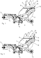
- die Vorrichtung zum Mähen, Vertikutieren und/oder Aufsammeln in Seitenansicht, wobei der Sammelbehälter sich in Arbeitsposition befindet,
- Fig.2
- die Vorrichtung zum Mähen, Vertikutieren und/oder Aufsammeln in Seitenansicht, wobei der Sammelbehälter sich in Entleerungsposition befindet,
- Fig.3
- die Vorrichtung zum Mähen, Vertikutieren und/oder Aufsammeln in Seitenansicht, wobei der Sammelbehälter sich wieder in Arbeitsposition, die Abdeckhaube sich jedoch noch in Öffnungsstellung befindet,
- Fig.4
- der Sammelbehälter der Vorrichtung in Arbeitsstellung mit sich noch in Öffnungsstellung befindlicher Abdeckhaube in perspektivischer Ansicht von schräg vorne,
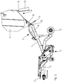
- Fig.5
- der Sammelbehälter der Vorrichtung in Arbeitsstellung mit sich noch in Öffnungsstellung befindlicher Abdeckhaube in perspektivischer Ansicht von schräg hinten und
- Fig.6
- die Anordnung des federnden Anschlagelementes zwischen Sammelbehälter und Abdeckhaube mit der Position der Abdeckhaube gemäß den
Fig. 3-5 im vergrößerten Maßstab und in der Ansicht nachFig.5 . - Vorrichtung zum Mähen, Vertikutieren und/oder Aufsammeln von Gras, Laub, Schmutz oder sonstigen in der Landschaftspflege anfallenden Stoffen in einen Sammelbehälter ist im Ausführungsbeispiel als gezogene Mäh- und Vertikutiermaschine ausgebildet. Diese Maschine weist den Rahmen 1 auf, der sich auf die Hinterräder 2 auf dem Boden und auf der im vorderen Bereich des Rahmens 1 angeordneten Zugdeichsel 3, die an eine nicht dargestellte Zugmaschine angekoppelt ist, abstützt. Im vorderen Bereich des Rahmens 1 ist eine Mäh- oder Vertikutiereinrichtung 4 in bekannter Weise angeordnet. Diese Einrichtung 4 wird von der Zapfwelle des Zugfahrzeugs über die Gelenkswelle 5 in bekannter Weise angetrieben. Hinter der Mäh- oder Vertikutiereinrichtung 4 ist an dem Rahmen der Sammelbehälter 6 mittels einer Hebe- und Kippeinrichtung 7 angeordnet. Diese Hebe- und Kippeinrichtung 7 weist auf jeder Seite des Sammelbehälters 6 einen Hydraulikzylinder 8 auf.
- Der Sammelbehälter 6 weist in seiner Arbeitsstellung gemäß
Figur 1 in seinem oberen Bereich die Entleerungsöffnung 9 auf. Die Entleerungsöffnung 9 wird in ihrem rückwärtigen Bereich 10 durch die Abdeckhaube 11 und in ihrem vorderen Bereich 12 durch eine Abdeckplatte 13 abgedeckt. Die Abdeckplatte 13 ist im vorderen Bereich mittels Gelenken 14 an den Sammelbehälter 5 schwenkbar angeordnet. Die Abdeckhaube 11 ist in ihrem hinteren Bereich an dem hinteren Bereich des Sammelbehälters 6 mittels Gelenken 15 schwenkbar befestigt. Die Abdeckplatte 13 und die Abdeckhaube 11 decken die Entleerungsöffnung 9 in der Arbeitsstellung des Sammelbehälters 6 ab. - Zum Entleeren des Sammelbehälters 6 von den in ihm gesammelten Stoffen lässt sich der Sammelbehälter 6 aus der in
Fig.1 dargestellten Arbeitsposition über die Hydraulikzylinder 8 der Hebe- und Kippeinrichtung 7 in die inFig. 2 dargestellte Entleerungsposition anheben und verschwenken. Hierbei geben die Abdeckhaube 11 und die Abdeckplatte 13 die Entleerungsöffnung 9 frei. Die Abdeckhaube 11 dient gleichzeitig als Übergabeklappe, wenn beispielsweise das Material ohne Verluste in einen nicht dargestellten Transportbehälter übergeben werden muss. - Die Gelenkvorrichtung 15, mittels welches die Abdeckhaube 11 an dem Sammelbehälter 6 angeordnet ist, befindet sich zwischen dem oberen - hinteren Bereich der Entleerungsöffnung 9 und dem hinteren Bereich der Abdeckhaube 11. Zwischen dem Sammelbehälter 6 und der Abdeckhaube 11 ist zumindest ein als Gasdruckfeder oder Gasdruckdämpfer ausgebildetes federndes Element 16 angeordnet. Das federnde Element 16 ist so angeordnet, dass das federnde Element 16 bei dem Bewegen des Sammelbehälters 6 aus der Entleerungsstellung in die Arbeitsstellung die Abdeckhaube 11 während des Schließvorganges der Entleerungsöffnung 9 durch die Abdeckhaube 11 abbremst. Hierdurch wird ein kontrolliertes Verschwenken der Abdeckhaube 11 mit einem sanften und leisen Verschließen der Entleerungsöffnung 9 durch die Abdeckhaube 11 erreicht. Durch das federnde Element 16 wird die Abdeckhaube 11 beim Verschwenken des Sammelbehälters 6 in die Arbeitsstellung in sanfter Weise in ihre Abdeckstellung gemäß
Fig. 1 verschwenkt, so dass sehr leise und kontrolliert die Entleerungsöffnung 9 durch die Abdeckhaube 11 geschlossen wird. - Im Bereich der Gelenkvorrichtung 15 ist ein federndes Anschlagelement 17, welches zwischen dem Sammelbehälter 6 und der Abdeckhaube 11 wirksam ist, angeordnet. Dieses federnde Anschlagelement 17 legt die Öffnungsposition der Abdeckhaube 11 fest und begrenzt das Öffnen der Abdeckhaube 11, wie die
Fig. 3 - 6 zeigen. Somit kann das federnde Anschlagelement 17 in der Endphase des Öffnungsvorganges die Abdeckhaube 11 in ihrer Endposition zusätzlich in schonender Weise abbremsen. So wird in schonender Weise die Endöffnungsposition für die Abdeckhaube 11 während der Entleerung des Sammelbehälters 6 festgelegt. - Das federnde Element 16 ist derart ausgebildet und angeordnet, dass es weder beim Öffnen noch beim Schließen der Entleerungsöffnung 9 durch die Abdeckhaube 11 aktiv das Öffnen oder das Schließen der Abdeckhaube unterstützt. Beim Verschwenken der Abdeckhaube 11 in die Entleerungsstellung des Sammelbehälter und der Abdeckhaube gemäß
Fig.2 unterstützt die Gasfeder 16 das Öffnen der Abdeckhaube nicht, sondern die Abdeckhaube 11 gelangt aufgrund ihrer Anordnung und ihres Gewichtes in die dargestellte Öffnungsstellung. Wenn der Behälter 6 leer ist und in die Arbeitsstellung zurück gedreht ist, wie inFig.3-6 dargestellt, wird die Abdeckhaube erforderlichenfalls von dem federnden Anschlagelement 17 in Richtung Schließstellung gedrückt und schwenkt dann aufgrund ihres Gewichtes in gebremster Weise durch die Gasfeder in Ihre Schließstellung gemäßFig.1 zurück. Da die Abdeckhaube aufgrund der Gasfeder 16 langsam in Schließposition zurückschwenkt, schließt die Abdeckhaube 11 kontrolliert, geräuschlos und schonend. Das Anschlagelement 17 ist als Druckfeder ausgebildet. - Weiterhin sorgt das federnde Anschlagelement 17 zu Beginn des Schließungsvorganges der Entleerungsöffnung 9 durch die Abdeckhaube 11 dafür, wenn sich der Sammelbehälter 9 und die Abdeckhaube 11 in der in
Fig.3-6 dargestellten Position des Sammelbehälters 6 und der Abdeckhaube 11 befindet, dass die Abdeckhaube 11 unmittelbar bei Beginn des Bringens des Sammelbehälters aus der Entleerungsposition in die Arbeitsposition auch in ungünstiger Position, wie in den vorgenannten Abbildung dargestellt, in Richtung Schließposition entsprechendFig.1 gedrückt wird. Dies wird in schonender Weise dadurch erreicht, dass das federnde Anschlagelement 17 zu Beginn des Schließvorganges der Entleerungsöffnung 9 durch die Abdeckhaube 11 an der Abdeckhaube 11 anliegt und die Abdeckhaube 11 in Richtung Abdeckstellung der Abdeckhaube 11 drückt.
Claims (5)
- Vorrichtung zum Mähen, Vertikutieren und/oder Aufsammeln von Gras, Laub, Schmutz oder sonstigen in der Landschaftspflege anfallenden Stoffen in einen Sammelbehälter, der an einem Rahmen (1) der Vorrichtung mittels einer Hebe- und/oder Kippeinrichtung (7) montiert ist, die den Sammelbehälter (6) zum Entleeren über diese Vorrichtung in eine Entleerungsstellung dreht und entleert, wobei der Sammelbehälter (6) in Arbeitsstellung in seinem oberen Bereich eine Entleerungsöffnung (9) aufweist, die in Arbeitsstellung durch eine mittels einer Gelenkvorrichtung (15) an den Sammelbehälter (6) verschwenkbar angeordneten Abdeckhaube (11) zumindest teilweise abgedeckt ist, wobei die Gelenkvorrichtung (15) sich zwischen dem oberen- hinteren Bereich der Entleerungsöffnung (9) und dem hinteren Bereich der Abdeckhaube (11) befindet, dadurch gekennzeichnet, zwischen dem Sammelbehälter (6) und der Abdeckhaube (11) ein federndes Element (16) angeordnet ist, dass das federnde Element (16) bei dem Bewegen des Sammelbehälters (6) aus der Entleerungsstellung in die Arbeitsstellung die Abdeckhaube (11) während des Schließvorganges der Entleerungsöffnung (9) durch die Abdeckhaube (11) abbremst, dass im Bereich der Gelenkvorrichtung (15) ein federndes Anschlagelement (17), welches zwischen dem Sammelbehälter (6) und der Abdeckhaube (11) wirksam ist, vorgesehen ist, welches das Öffnen der Abdeckhaube (11) festlegt und begrenzt.
- Vorrichtung nach Anspruch 1, dadurch gekennzeichnet, dass das federnde Anschlagelement (11) zu Beginn des Schließvorganges der Entleerungsöffnung (9) durch die Abdeckhaube (11) an der Abdeckhaube (11) anliegt und die Abdeckhaube (11) in Richtung Abdeckstellung der Abdeckhaube (11) drückt.
- Vorrichtung nach Anspruch 1, dadurch gekennzeichnet, dass das federnde Anschlagelement (11) eine Druckfeder aufweist.
- Vorrichtung nach einem der vorstehenden Ansprüche, dadurch gekennzeichnet, dass das federnde Element (16) zwischen Sammelbehälter (6) und Abdeckhaube (11) als Gasdruckfeder und/oder Gasdruckdämpfer ausgebildet ist.
- Vorrichtung nach zumindest einem der vorstehenden Ansprüche, dadurch gekennzeichnet, dass das federnde Element (16) derart ausgebildet ist, dass es weder beim Öffnen noch beim Schließen der Entleerungsöffnung (9) durch die Abdeckhaube (11) aktiv das Öffnen oder das Schließen der Abdeckhaube (11) unterstützt.
Applications Claiming Priority (1)
| Application Number | Priority Date | Filing Date | Title |
|---|---|---|---|
| DE102015114621.5A DE102015114621A1 (de) | 2015-09-02 | 2015-09-02 | Vorrichtung zum Mähen, Vertikutieren und/oder Aufsammeln |
Publications (2)
| Publication Number | Publication Date |
|---|---|
| EP3138378A1 EP3138378A1 (de) | 2017-03-08 |
| EP3138378B1 true EP3138378B1 (de) | 2018-09-26 |
Family
ID=57047149
Family Applications (1)
| Application Number | Title | Priority Date | Filing Date |
|---|---|---|---|
| EP16401052.2A Active EP3138378B1 (de) | 2015-09-02 | 2016-08-30 | Vorrichtung zum mähen, vertikutieren und/oder aufsammeln |
Country Status (2)
| Country | Link |
|---|---|
| EP (1) | EP3138378B1 (de) |
| DE (1) | DE102015114621A1 (de) |
Families Citing this family (1)
| Publication number | Priority date | Publication date | Assignee | Title |
|---|---|---|---|---|
| CN111684875A (zh) * | 2020-06-12 | 2020-09-22 | 石河子大学 | 一种新型残膜回收打包机 |
Family Cites Families (6)
| Publication number | Priority date | Publication date | Assignee | Title |
|---|---|---|---|---|
| GB892309A (en) * | 1959-11-06 | 1962-03-28 | Theodor William Reinhold | Improvements in and relating to grass catchers for rotary-scythe mowers |
| US4456141A (en) * | 1981-11-19 | 1984-06-26 | Industrial Containers Pty. Ltd., Cnr. Moore | Waste containers |
| DE9405833U1 (de) | 1994-04-11 | 1994-07-21 | Maschinen-Mohr, Inh. Hermann Mohr, 91792 Ellingen | Sammeleinrichtung für Gras, Laub, Schmutz mit integriertem Gebläse und Hochentleerung |
| DE19755196A1 (de) * | 1997-12-12 | 1999-06-17 | Amazonen Werke Dreyer H | Fahrbare Sammelmaschine |
| ITVI20040010A1 (it) * | 2004-01-21 | 2004-04-21 | Berti Macchine Agricole Srl | Macchina trinciatrice perfezionata |
| FR2912434B1 (fr) * | 2007-02-14 | 2011-07-01 | Jungo Voirie | Cuve de reception pour dechets preleves par un vehicule de voirie |
-
2015
- 2015-09-02 DE DE102015114621.5A patent/DE102015114621A1/de active Granted
-
2016
- 2016-08-30 EP EP16401052.2A patent/EP3138378B1/de active Active
Non-Patent Citations (1)
| Title |
|---|
| None * |
Also Published As
| Publication number | Publication date |
|---|---|
| DE102015114621A1 (de) | 2017-03-02 |
| EP3138378A1 (de) | 2017-03-08 |
Similar Documents
| Publication | Publication Date | Title |
|---|---|---|
| DE102014106696A1 (de) | Feldhäcksler | |
| DE202017104191U1 (de) | Schneidmesser-Überlastsicherung | |
| WO2014067508A1 (de) | Anbaudrehpflug mit einschwenkbegrenzung | |
| EP2926643B1 (de) | Landwirtschaftliche Maschine | |
| EP0861584A2 (de) | Schneidwerk für landwirtschaftliche Maschine | |
| DE2127971A1 (de) | Baumschneidmaschine | |
| EP3138378B1 (de) | Vorrichtung zum mähen, vertikutieren und/oder aufsammeln | |
| EP4551001A1 (de) | Mähvorrichtung für ein trägerfahrzeug | |
| DE2632002C2 (de) | Mähmaschine | |
| DE102012110178B4 (de) | Landwirtschaftliches Arbeitsgerät | |
| EP0205854A1 (de) | Fördervorrichtung für landwirtschaftliche Ladewagen | |
| DE102005050491B4 (de) | Rodeaggregat sowie Erntemaschine mit einem solchen Aggregat | |
| DE102015100273A1 (de) | Landwirtschaftliches Arbeitsgerät mit Zusatzfahrwerk | |
| DE102006059265A1 (de) | Landwirtschaftliche Presse | |
| EP1110443B1 (de) | Mähaufbereiter | |
| DE1507188A1 (de) | Quetsch- oder Knickzetter | |
| EP4028599A1 (de) | Greifer | |
| EP1738634A1 (de) | Erntegutaufnahmeeinrichtung und Erntemaschine | |
| DE102004025478B4 (de) | Landwirtschaftliche Maschine | |
| EP3069596B1 (de) | Feldhäcksler | |
| DE1507193A1 (de) | Feldhaecksler | |
| DE102010036308A1 (de) | Dosiereinrichtung | |
| DE102005009253B4 (de) | Rückeschild | |
| DE102022107254A1 (de) | Landwirtschaftlicher Mäher zum Betreiben im Schubbetrieb | |
| DE202014003637U1 (de) | Landwirtschaftliche Maschine |
Legal Events
| Date | Code | Title | Description |
|---|---|---|---|
| PUAI | Public reference made under article 153(3) epc to a published international application that has entered the european phase |
Free format text: ORIGINAL CODE: 0009012 |
|
| STAA | Information on the status of an ep patent application or granted ep patent |
Free format text: STATUS: THE APPLICATION HAS BEEN PUBLISHED |
|
| AK | Designated contracting states |
Kind code of ref document: A1 Designated state(s): AL AT BE BG CH CY CZ DE DK EE ES FI FR GB GR HR HU IE IS IT LI LT LU LV MC MK MT NL NO PL PT RO RS SE SI SK SM TR |
|
| AX | Request for extension of the european patent |
Extension state: BA ME |
|
| STAA | Information on the status of an ep patent application or granted ep patent |
Free format text: STATUS: REQUEST FOR EXAMINATION WAS MADE |
|
| 17P | Request for examination filed |
Effective date: 20170727 |
|
| RBV | Designated contracting states (corrected) |
Designated state(s): AL AT BE BG CH CY CZ DE DK EE ES FI FR GB GR HR HU IE IS IT LI LT LU LV MC MK MT NL NO PL PT RO RS SE SI SK SM TR |
|
| RIC1 | Information provided on ipc code assigned before grant |
Ipc: A01D 43/063 20060101AFI20180524BHEP Ipc: A01G 3/00 20060101ALN20180524BHEP Ipc: B65F 1/16 20060101ALI20180524BHEP Ipc: A01B 45/02 20060101ALN20180524BHEP |
|
| INTG | Intention to grant announced |
Effective date: 20180611 |
|
| GRAP | Despatch of communication of intention to grant a patent |
Free format text: ORIGINAL CODE: EPIDOSNIGR1 |
|
| STAA | Information on the status of an ep patent application or granted ep patent |
Free format text: STATUS: GRANT OF PATENT IS INTENDED |
|
| GRAS | Grant fee paid |
Free format text: ORIGINAL CODE: EPIDOSNIGR3 |
|
| GRAA | (expected) grant |
Free format text: ORIGINAL CODE: 0009210 |
|
| STAA | Information on the status of an ep patent application or granted ep patent |
Free format text: STATUS: THE PATENT HAS BEEN GRANTED |
|
| AK | Designated contracting states |
Kind code of ref document: B1 Designated state(s): AL AT BE BG CH CY CZ DE DK EE ES FI FR GB GR HR HU IE IS IT LI LT LU LV MC MK MT NL NO PL PT RO RS SE SI SK SM TR |
|
| REG | Reference to a national code |
Ref country code: GB Ref legal event code: FG4D Free format text: NOT ENGLISH |
|
| REG | Reference to a national code |
Ref country code: CH Ref legal event code: EP |
|
| REG | Reference to a national code |
Ref country code: AT Ref legal event code: REF Ref document number: 1044901 Country of ref document: AT Kind code of ref document: T Effective date: 20181015 |
|
| REG | Reference to a national code |
Ref country code: IE Ref legal event code: FG4D Free format text: LANGUAGE OF EP DOCUMENT: GERMAN |
|
| REG | Reference to a national code |
Ref country code: DE Ref legal event code: R096 Ref document number: 502016002096 Country of ref document: DE |
|
| REG | Reference to a national code |
Ref country code: NL Ref legal event code: MP Effective date: 20180926 |
|
| PG25 | Lapsed in a contracting state [announced via postgrant information from national office to epo] |
Ref country code: GR Free format text: LAPSE BECAUSE OF FAILURE TO SUBMIT A TRANSLATION OF THE DESCRIPTION OR TO PAY THE FEE WITHIN THE PRESCRIBED TIME-LIMIT Effective date: 20181227 Ref country code: NO Free format text: LAPSE BECAUSE OF FAILURE TO SUBMIT A TRANSLATION OF THE DESCRIPTION OR TO PAY THE FEE WITHIN THE PRESCRIBED TIME-LIMIT Effective date: 20181226 Ref country code: FI Free format text: LAPSE BECAUSE OF FAILURE TO SUBMIT A TRANSLATION OF THE DESCRIPTION OR TO PAY THE FEE WITHIN THE PRESCRIBED TIME-LIMIT Effective date: 20180926 Ref country code: LT Free format text: LAPSE BECAUSE OF FAILURE TO SUBMIT A TRANSLATION OF THE DESCRIPTION OR TO PAY THE FEE WITHIN THE PRESCRIBED TIME-LIMIT Effective date: 20180926 Ref country code: RS Free format text: LAPSE BECAUSE OF FAILURE TO SUBMIT A TRANSLATION OF THE DESCRIPTION OR TO PAY THE FEE WITHIN THE PRESCRIBED TIME-LIMIT Effective date: 20180926 Ref country code: BG Free format text: LAPSE BECAUSE OF FAILURE TO SUBMIT A TRANSLATION OF THE DESCRIPTION OR TO PAY THE FEE WITHIN THE PRESCRIBED TIME-LIMIT Effective date: 20181226 |
|
| REG | Reference to a national code |
Ref country code: LT Ref legal event code: MG4D |
|
| PG25 | Lapsed in a contracting state [announced via postgrant information from national office to epo] |
Ref country code: LV Free format text: LAPSE BECAUSE OF FAILURE TO SUBMIT A TRANSLATION OF THE DESCRIPTION OR TO PAY THE FEE WITHIN THE PRESCRIBED TIME-LIMIT Effective date: 20180926 Ref country code: AL Free format text: LAPSE BECAUSE OF FAILURE TO SUBMIT A TRANSLATION OF THE DESCRIPTION OR TO PAY THE FEE WITHIN THE PRESCRIBED TIME-LIMIT Effective date: 20180926 Ref country code: HR Free format text: LAPSE BECAUSE OF FAILURE TO SUBMIT A TRANSLATION OF THE DESCRIPTION OR TO PAY THE FEE WITHIN THE PRESCRIBED TIME-LIMIT Effective date: 20180926 |
|
| PG25 | Lapsed in a contracting state [announced via postgrant information from national office to epo] |
Ref country code: NL Free format text: LAPSE BECAUSE OF FAILURE TO SUBMIT A TRANSLATION OF THE DESCRIPTION OR TO PAY THE FEE WITHIN THE PRESCRIBED TIME-LIMIT Effective date: 20180926 Ref country code: EE Free format text: LAPSE BECAUSE OF FAILURE TO SUBMIT A TRANSLATION OF THE DESCRIPTION OR TO PAY THE FEE WITHIN THE PRESCRIBED TIME-LIMIT Effective date: 20180926 Ref country code: IS Free format text: LAPSE BECAUSE OF FAILURE TO SUBMIT A TRANSLATION OF THE DESCRIPTION OR TO PAY THE FEE WITHIN THE PRESCRIBED TIME-LIMIT Effective date: 20190126 Ref country code: PL Free format text: LAPSE BECAUSE OF FAILURE TO SUBMIT A TRANSLATION OF THE DESCRIPTION OR TO PAY THE FEE WITHIN THE PRESCRIBED TIME-LIMIT Effective date: 20180926 Ref country code: ES Free format text: LAPSE BECAUSE OF FAILURE TO SUBMIT A TRANSLATION OF THE DESCRIPTION OR TO PAY THE FEE WITHIN THE PRESCRIBED TIME-LIMIT Effective date: 20180926 Ref country code: CZ Free format text: LAPSE BECAUSE OF FAILURE TO SUBMIT A TRANSLATION OF THE DESCRIPTION OR TO PAY THE FEE WITHIN THE PRESCRIBED TIME-LIMIT Effective date: 20180926 Ref country code: IT Free format text: LAPSE BECAUSE OF FAILURE TO SUBMIT A TRANSLATION OF THE DESCRIPTION OR TO PAY THE FEE WITHIN THE PRESCRIBED TIME-LIMIT Effective date: 20180926 Ref country code: RO Free format text: LAPSE BECAUSE OF FAILURE TO SUBMIT A TRANSLATION OF THE DESCRIPTION OR TO PAY THE FEE WITHIN THE PRESCRIBED TIME-LIMIT Effective date: 20180926 |
|
| PG25 | Lapsed in a contracting state [announced via postgrant information from national office to epo] |
Ref country code: PT Free format text: LAPSE BECAUSE OF FAILURE TO SUBMIT A TRANSLATION OF THE DESCRIPTION OR TO PAY THE FEE WITHIN THE PRESCRIBED TIME-LIMIT Effective date: 20190126 Ref country code: SM Free format text: LAPSE BECAUSE OF FAILURE TO SUBMIT A TRANSLATION OF THE DESCRIPTION OR TO PAY THE FEE WITHIN THE PRESCRIBED TIME-LIMIT Effective date: 20180926 Ref country code: SK Free format text: LAPSE BECAUSE OF FAILURE TO SUBMIT A TRANSLATION OF THE DESCRIPTION OR TO PAY THE FEE WITHIN THE PRESCRIBED TIME-LIMIT Effective date: 20180926 |
|
| REG | Reference to a national code |
Ref country code: DE Ref legal event code: R097 Ref document number: 502016002096 Country of ref document: DE |
|
| PG25 | Lapsed in a contracting state [announced via postgrant information from national office to epo] |
Ref country code: DK Free format text: LAPSE BECAUSE OF FAILURE TO SUBMIT A TRANSLATION OF THE DESCRIPTION OR TO PAY THE FEE WITHIN THE PRESCRIBED TIME-LIMIT Effective date: 20180926 |
|
| PLBE | No opposition filed within time limit |
Free format text: ORIGINAL CODE: 0009261 |
|
| STAA | Information on the status of an ep patent application or granted ep patent |
Free format text: STATUS: NO OPPOSITION FILED WITHIN TIME LIMIT |
|
| 26N | No opposition filed |
Effective date: 20190627 |
|
| PG25 | Lapsed in a contracting state [announced via postgrant information from national office to epo] |
Ref country code: SI Free format text: LAPSE BECAUSE OF FAILURE TO SUBMIT A TRANSLATION OF THE DESCRIPTION OR TO PAY THE FEE WITHIN THE PRESCRIBED TIME-LIMIT Effective date: 20180926 |
|
| PG25 | Lapsed in a contracting state [announced via postgrant information from national office to epo] |
Ref country code: TR Free format text: LAPSE BECAUSE OF FAILURE TO SUBMIT A TRANSLATION OF THE DESCRIPTION OR TO PAY THE FEE WITHIN THE PRESCRIBED TIME-LIMIT Effective date: 20180926 |
|
| PG25 | Lapsed in a contracting state [announced via postgrant information from national office to epo] |
Ref country code: LU Free format text: LAPSE BECAUSE OF NON-PAYMENT OF DUE FEES Effective date: 20190830 Ref country code: MC Free format text: LAPSE BECAUSE OF FAILURE TO SUBMIT A TRANSLATION OF THE DESCRIPTION OR TO PAY THE FEE WITHIN THE PRESCRIBED TIME-LIMIT Effective date: 20180926 Ref country code: CH Free format text: LAPSE BECAUSE OF NON-PAYMENT OF DUE FEES Effective date: 20190831 Ref country code: LI Free format text: LAPSE BECAUSE OF NON-PAYMENT OF DUE FEES Effective date: 20190831 |
|
| REG | Reference to a national code |
Ref country code: BE Ref legal event code: MM Effective date: 20190831 |
|
| PG25 | Lapsed in a contracting state [announced via postgrant information from national office to epo] |
Ref country code: IE Free format text: LAPSE BECAUSE OF NON-PAYMENT OF DUE FEES Effective date: 20190830 |
|
| PG25 | Lapsed in a contracting state [announced via postgrant information from national office to epo] |
Ref country code: BE Free format text: LAPSE BECAUSE OF NON-PAYMENT OF DUE FEES Effective date: 20190831 |
|
| GBPC | Gb: european patent ceased through non-payment of renewal fee |
Effective date: 20200830 |
|
| REG | Reference to a national code |
Ref country code: DE Ref legal event code: R081 Ref document number: 502016002096 Country of ref document: DE Owner name: AMAZONEN-WERKE H. DREYER SE & CO. KG, DE Free format text: FORMER OWNER: AMAZONEN-WERKE H. DREYER GMBH & CO. KG, 49205 HASBERGEN, DE |
|
| PG25 | Lapsed in a contracting state [announced via postgrant information from national office to epo] |
Ref country code: CY Free format text: LAPSE BECAUSE OF FAILURE TO SUBMIT A TRANSLATION OF THE DESCRIPTION OR TO PAY THE FEE WITHIN THE PRESCRIBED TIME-LIMIT Effective date: 20180926 |
|
| PG25 | Lapsed in a contracting state [announced via postgrant information from national office to epo] |
Ref country code: SE Free format text: LAPSE BECAUSE OF NON-PAYMENT OF DUE FEES Effective date: 20180926 |
|
| PG25 | Lapsed in a contracting state [announced via postgrant information from national office to epo] |
Ref country code: HU Free format text: LAPSE BECAUSE OF FAILURE TO SUBMIT A TRANSLATION OF THE DESCRIPTION OR TO PAY THE FEE WITHIN THE PRESCRIBED TIME-LIMIT; INVALID AB INITIO Effective date: 20160830 Ref country code: MT Free format text: LAPSE BECAUSE OF FAILURE TO SUBMIT A TRANSLATION OF THE DESCRIPTION OR TO PAY THE FEE WITHIN THE PRESCRIBED TIME-LIMIT Effective date: 20180926 |
|
| PG25 | Lapsed in a contracting state [announced via postgrant information from national office to epo] |
Ref country code: GB Free format text: LAPSE BECAUSE OF NON-PAYMENT OF DUE FEES Effective date: 20200830 |
|
| PG25 | Lapsed in a contracting state [announced via postgrant information from national office to epo] |
Ref country code: MK Free format text: LAPSE BECAUSE OF FAILURE TO SUBMIT A TRANSLATION OF THE DESCRIPTION OR TO PAY THE FEE WITHIN THE PRESCRIBED TIME-LIMIT Effective date: 20180926 |
|
| REG | Reference to a national code |
Ref country code: AT Ref legal event code: MM01 Ref document number: 1044901 Country of ref document: AT Kind code of ref document: T Effective date: 20210830 |
|
| PG25 | Lapsed in a contracting state [announced via postgrant information from national office to epo] |
Ref country code: AT Free format text: LAPSE BECAUSE OF NON-PAYMENT OF DUE FEES Effective date: 20210830 |
|
| P01 | Opt-out of the competence of the unified patent court (upc) registered |
Effective date: 20230523 |
|
| PGFP | Annual fee paid to national office [announced via postgrant information from national office to epo] |
Ref country code: DE Payment date: 20250702 Year of fee payment: 10 |
|
| PGFP | Annual fee paid to national office [announced via postgrant information from national office to epo] |
Ref country code: FR Payment date: 20250703 Year of fee payment: 10 |