EP3137916B1 - Procédé de gestion de mode veille de batterie - Google Patents
Procédé de gestion de mode veille de batterie Download PDFInfo
- Publication number
- EP3137916B1 EP3137916B1 EP15723351.1A EP15723351A EP3137916B1 EP 3137916 B1 EP3137916 B1 EP 3137916B1 EP 15723351 A EP15723351 A EP 15723351A EP 3137916 B1 EP3137916 B1 EP 3137916B1
- Authority
- EP
- European Patent Office
- Prior art keywords
- battery
- battery module
- state
- management system
- charge
- Prior art date
- Legal status (The legal status is an assumption and is not a legal conclusion. Google has not performed a legal analysis and makes no representation as to the accuracy of the status listed.)
- Active
Links
- 238000007726 management method Methods 0.000 title description 167
- 238000000034 method Methods 0.000 claims description 25
- 230000004044 response Effects 0.000 claims description 17
- 230000008859 change Effects 0.000 claims description 3
- 238000005259 measurement Methods 0.000 description 27
- 238000012544 monitoring process Methods 0.000 description 12
- 230000007704 transition Effects 0.000 description 8
- 238000013461 design Methods 0.000 description 7
- 230000006870 function Effects 0.000 description 7
- 239000004020 conductor Substances 0.000 description 6
- 238000013021 overheating Methods 0.000 description 6
- 230000000994 depressogenic effect Effects 0.000 description 5
- 238000007599 discharging Methods 0.000 description 5
- 238000004519 manufacturing process Methods 0.000 description 5
- 238000012545 processing Methods 0.000 description 5
- 239000004065 semiconductor Substances 0.000 description 5
- 230000008878 coupling Effects 0.000 description 4
- 238000010168 coupling process Methods 0.000 description 4
- 238000005859 coupling reaction Methods 0.000 description 4
- 238000011161 development Methods 0.000 description 4
- 238000005516 engineering process Methods 0.000 description 4
- 230000005669 field effect Effects 0.000 description 4
- 239000007787 solid Substances 0.000 description 4
- 230000008901 benefit Effects 0.000 description 3
- 230000000295 complement effect Effects 0.000 description 3
- 238000010586 diagram Methods 0.000 description 3
- 230000008569 process Effects 0.000 description 3
- 230000007420 reactivation Effects 0.000 description 3
- 239000000126 substance Substances 0.000 description 3
- 238000012546 transfer Methods 0.000 description 3
- 230000000007 visual effect Effects 0.000 description 3
- WHXSMMKQMYFTQS-UHFFFAOYSA-N Lithium Chemical compound [Li] WHXSMMKQMYFTQS-UHFFFAOYSA-N 0.000 description 2
- 238000004458 analytical method Methods 0.000 description 2
- 238000004364 calculation method Methods 0.000 description 2
- 239000003086 colorant Substances 0.000 description 2
- 230000001276 controlling effect Effects 0.000 description 2
- 230000000881 depressing effect Effects 0.000 description 2
- 238000001514 detection method Methods 0.000 description 2
- 239000003792 electrolyte Substances 0.000 description 2
- 230000036541 health Effects 0.000 description 2
- 229910052744 lithium Inorganic materials 0.000 description 2
- 229910001416 lithium ion Inorganic materials 0.000 description 2
- 238000012986 modification Methods 0.000 description 2
- 230000004048 modification Effects 0.000 description 2
- 230000002618 waking effect Effects 0.000 description 2
- HBBGRARXTFLTSG-UHFFFAOYSA-N Lithium ion Chemical compound [Li+] HBBGRARXTFLTSG-UHFFFAOYSA-N 0.000 description 1
- 230000002411 adverse Effects 0.000 description 1
- 238000006243 chemical reaction Methods 0.000 description 1
- 238000002485 combustion reaction Methods 0.000 description 1
- 238000004891 communication Methods 0.000 description 1
- 238000001816 cooling Methods 0.000 description 1
- 230000000694 effects Effects 0.000 description 1
- 238000004146 energy storage Methods 0.000 description 1
- 239000011521 glass Substances 0.000 description 1
- 230000005484 gravity Effects 0.000 description 1
- 230000000415 inactivating effect Effects 0.000 description 1
- 238000003780 insertion Methods 0.000 description 1
- 230000037431 insertion Effects 0.000 description 1
- 230000010354 integration Effects 0.000 description 1
- GELKBWJHTRAYNV-UHFFFAOYSA-K lithium iron phosphate Chemical compound [Li+].[Fe+2].[O-]P([O-])([O-])=O GELKBWJHTRAYNV-UHFFFAOYSA-K 0.000 description 1
- 239000000463 material Substances 0.000 description 1
- 229910052987 metal hydride Inorganic materials 0.000 description 1
- 238000012806 monitoring device Methods 0.000 description 1
- 229920000642 polymer Polymers 0.000 description 1
- 230000001105 regulatory effect Effects 0.000 description 1
- 238000013519 translation Methods 0.000 description 1
- XLYOFNOQVPJJNP-UHFFFAOYSA-N water Substances O XLYOFNOQVPJJNP-UHFFFAOYSA-N 0.000 description 1
Images


Classifications
-
- H—ELECTRICITY
- H01—ELECTRIC ELEMENTS
- H01M—PROCESSES OR MEANS, e.g. BATTERIES, FOR THE DIRECT CONVERSION OF CHEMICAL ENERGY INTO ELECTRICAL ENERGY
- H01M10/00—Secondary cells; Manufacture thereof
- H01M10/42—Methods or arrangements for servicing or maintenance of secondary cells or secondary half-cells
- H01M10/425—Structural combination with electronic components, e.g. electronic circuits integrated to the outside of the casing
- H01M10/4257—Smart batteries, e.g. electronic circuits inside the housing of the cells or batteries
-
- G—PHYSICS
- G05—CONTROLLING; REGULATING
- G05B—CONTROL OR REGULATING SYSTEMS IN GENERAL; FUNCTIONAL ELEMENTS OF SUCH SYSTEMS; MONITORING OR TESTING ARRANGEMENTS FOR SUCH SYSTEMS OR ELEMENTS
- G05B11/00—Automatic controllers
- G05B11/01—Automatic controllers electric
-
- H—ELECTRICITY
- H01—ELECTRIC ELEMENTS
- H01M—PROCESSES OR MEANS, e.g. BATTERIES, FOR THE DIRECT CONVERSION OF CHEMICAL ENERGY INTO ELECTRICAL ENERGY
- H01M10/00—Secondary cells; Manufacture thereof
- H01M10/42—Methods or arrangements for servicing or maintenance of secondary cells or secondary half-cells
- H01M10/48—Accumulators combined with arrangements for measuring, testing or indicating the condition of cells, e.g. the level or density of the electrolyte
- H01M10/486—Accumulators combined with arrangements for measuring, testing or indicating the condition of cells, e.g. the level or density of the electrolyte for measuring temperature
-
- H—ELECTRICITY
- H01—ELECTRIC ELEMENTS
- H01M—PROCESSES OR MEANS, e.g. BATTERIES, FOR THE DIRECT CONVERSION OF CHEMICAL ENERGY INTO ELECTRICAL ENERGY
- H01M10/00—Secondary cells; Manufacture thereof
- H01M10/42—Methods or arrangements for servicing or maintenance of secondary cells or secondary half-cells
- H01M10/48—Accumulators combined with arrangements for measuring, testing or indicating the condition of cells, e.g. the level or density of the electrolyte
- H01M10/488—Cells or batteries combined with indicating means for external visualization of the condition, e.g. by change of colour or of light density
-
- H—ELECTRICITY
- H01—ELECTRIC ELEMENTS
- H01M—PROCESSES OR MEANS, e.g. BATTERIES, FOR THE DIRECT CONVERSION OF CHEMICAL ENERGY INTO ELECTRICAL ENERGY
- H01M10/00—Secondary cells; Manufacture thereof
- H01M10/42—Methods or arrangements for servicing or maintenance of secondary cells or secondary half-cells
- H01M10/425—Structural combination with electronic components, e.g. electronic circuits integrated to the outside of the casing
- H01M2010/4271—Battery management systems including electronic circuits, e.g. control of current or voltage to keep battery in healthy state, cell balancing
-
- H—ELECTRICITY
- H01—ELECTRIC ELEMENTS
- H01M—PROCESSES OR MEANS, e.g. BATTERIES, FOR THE DIRECT CONVERSION OF CHEMICAL ENERGY INTO ELECTRICAL ENERGY
- H01M2220/00—Batteries for particular applications
- H01M2220/20—Batteries in motive systems, e.g. vehicle, ship, plane
Definitions
- the invention relates generally to battery devices and systems and, more particularly, to a vehicle battery management system.
- Batteries composed of one or more electrochemical cells capable of converting chemical energy into a more readily usable form of electrical energy are widely employed in many industries and applications.
- many such batteries are starting, lighting, and ignition (SLI) batteries capable of starting the internal combustion engines of motorcycles, cars, trucks, and other vehicles.
- Batteries of this type can typically be discharged and replenished with charge in multiple cycles before the life cycle of the battery is depleted.
- SLI starting, lighting, and ignition
- Batteries of this type can typically be discharged and replenished with charge in multiple cycles before the life cycle of the battery is depleted.
- the charge level of the battery is unknown.
- the battery may not function if the charge level of the battery has been depleted, for example, during the time the battery was on a display shelf before purchase.
- EP 1 202 457 A1 is related to a method for switching off battery supplied electronic devices and mobile telephone equipped therewith.
- US 2007/273329 A1 is related to a storage battery unit, wherein a starting circuit includes a main switch that holds an OFF state in a state before a load exceeding a set value is connected to the storage battery unit and interrupts supply of electric power from the storage battery unit to the monitoring device.
- DE 41 31 981 A1 is related to a battery powered electrical device with constant current electrical load having an electronic switch controlled by electronic timing element which isolates battery from load to prevent excessive discharging.
- US 2007/001680 A1 relates generally to condition detection and indicating means for an electrical storage battery, wherein to avoid draining the battery, the microcontroller enters a sleep mode in the event that the battery voltage does not change for a significant period of time, as will happen in a vehicle battery when the vehicle is out of use. No current measurements are made in sleep mode.
- US 2005/038614 A1 relates to monitoring batteries.
- DE 10 2011 115908 A1 relates to a circuit arrangement of battery management system for energy storage device used in electric bicycle, transmits information of current and temperature of battery to component within electric drive through communication line.
- US 2004/189256 A1 is related to a state of charge indicator that is removably attachable to a battery.
- US 2002/089318 A1 is related to electronic devices for the control of rechargeable batteries, such as those that prevent damage caused to a rechargeable battery pack due to operating conditions that might be outside its design parameters and further to a device for switching power from the battery pack or between multiple battery packs. It further is directed to a power saving arrangement for rechargeable battery packs, wherein the battery controller has an active mode and a sleep mode. In active mode, controller monitors battery as described herein. In a sleep mode, however, battery controller can cease activity, and for example can be configured so that it does not measure current, voltage, or temperature.
- WO 2013/147070 A1 is related to a semiconductor device, power supply control method of semiconductor device, and sensor node, wherein each power supply region is a region configured to operate based on power to be supplied by a switch associated with the power supply region. That is, when a certain power supply region is activated, the power is supplied to the power supply region by short-circuiting the switch associated with the power supply region. On the other hand, when the power supply region is inactivated, the power to be supplied to the power supply region is interrupted by opening the switch associated with the power supply region. By appropriately inactivating the power supply region, transition to a sleep mode is made. Then, the semiconductor device activates the power supply region that has been inactivated if needed, thereby returning to an active mode.
- US 2010/141216 A1 relates to a battery system that includes a battery and a battery protection apparatus.
- the battery protection apparatus protects the battery from over-discharge.
- the battery protection apparatus includes a voltage controlled switch, a start switch, and a voltage detecting unit.
- the voltage controlled switch establishes an electrical connection between the battery and the load.
- the start switch turns on the voltage controlled switch when actuated.
- the voltage detecting unit detects a battery voltage of the battery and generates a detecting voltage according to the battery voltage.
- the voltage controlled switch is turned off when the detecting voltage is lower than a predetermined value.
- US 2012/013189 A1 is related to system for managing, e.g., a battery pack utilized in, e.g., automobile, has logic/controller determining whether current is above predetermined value and voltage is below lower threshold for electrically disconnecting battery cells from load.
- the present disclosure relates to a method for managing a battery module as defined in claim 1.
- Systems and methods may include a battery management system including one or more sensors and processing circuitry.
- the battery management system may monitor parameters of the battery, such as voltage, temperature, current, and state of charge. Additionally, the battery management system may protect the battery by performing cell balancing. Furthermore, the battery management system may protect the battery by preventing over-discharge (e.g., under-voltage) of the battery and/or of individual cells of the battery, input over-voltage, input over-current, and over-heating by monitoring operational parameters of the battery and placing the battery into a sleep mode in response to detected undesirable operating conditions.
- over-discharge e.g., under-voltage
- the battery management system may include a connector adapted to couple a state of charge indicator to the battery management system so that the state of charge indicator may provide an indication of the state of charge of the battery.
- the state of charge indicator may be tethered to the battery via the connector.
- the state of charge indicator may also interface between the battery management system and a charging system.
- the state of charge indicator may include a reset button (e.g., momentary contact switch) adapted to allow for manually placing the battery into a sleep mode and manually reactivating the battery (i.e., "waking" from sleep mode).
- FIG. 1 illustrates a battery system 10 including a battery 12 disposed in a vehicle 14.
- the battery 12 may typically be used in a vehicle, as shown, which may be a car, truck, boat, motorcycle, recreational vehicle, golf cart, four wheeler, offroad vehicle, power sports vehicle, power water craft, or other vehicle that uses battery power. While the battery 12 is illustrated as being positioned in the trunk or rear of the vehicle 14, the location of the battery 12 may differ in other embodiments. For example, the position of the battery 12 may be selected based on the available space within the vehicle, the desired weight balance of the vehicle, the location of other components used with the battery system 10 (e.g., cooling devices, etc.), and a variety of other considerations.
- the battery may be somewhat difficult to access, and aspects of the present disclosure allow for checking the state of charge of the battery, charging the battery, controlling sleep mode and other operations of the battery, and so forth, while the battery is still installed, greatly facilitating these operations when such access is difficult.
- the battery 12 may be a starting, lighting, and ignition (SLI) battery of any desired design, type, voltage, and capacity, or the battery 12 may be a deep cycle battery, depending on the vehicle type and the application, Moreover, the battery may be designed and constructed in accordance with any currently known or later developed technology, such as wet cell technologies, glass mat technologies, gel cell technologies, etc. In some embodiments, the battery 12 may be a lithium-ion battery. Further, in some embodiments, the battery 12 may be a summer-only battery and may not be adapted for use during the winter. Similarly, when the vehicle is only used sporadically or seasonally, the techniques described allow for management of the battery charge and functions to accommodate such selected use.
- SLI starting, lighting, and ignition
- the battery 12 includes positive and negative terminals 16, which may be coupled to a wiring harness or other components within the vehicle 14 that utilize the voltage output of the battery 12.
- Present embodiments of the battery 12 may also include a connector 18 (e.g., a multi-conductor connector), such as a female plug, to couple external electrical conductors to internal components of the battery 12.
- the connector 18 may couple a state of charge indicator 20 to the battery 12 via a lead 22 of the state of charge indicator 20 disposed in the connector 18.
- the state of charge indicator 20 may receive data from the battery 12, such as the voltage of the battery 12, and may provide an indication of the state of charge of the battery 12.
- the state of charge indicator 20 may be adapted to couple to a battery charger/maintainer 24 with a lead 26.
- the state of charge indicator 20 is electrically coupled to the charger/maintainer 24, electrical charging power may be applied through the lead 26, the state of charge indicator 20, the lead 22, and the connector 18, in order, to build up a charge in the battery 12.
- the battery charger/maintainer 24 may receive power from a power grid 28 or other power source, which provides AC power to the battery system 10. It should be noted that the battery charger/maintainer 24 may be any desirable battery charger or battery maintainer configured for use with the battery 12. Battery chargers typically provide a high charging current to the battery 12 in order to charge the battery 12 relatively quickly (e.g., overnight), while battery maintainers typically provide a lower current "trickle" flow of charging power to the battery 12.
- the battery charger/maintainer 24 may be portable, or may have a fixed location. Moreover, the charger/maintainer may implement any desired charging regime, such as regimes based on sensed voltage, stage of charge, battery voltage and capacity, and so forth.
- FIG. 2 illustrates a motorcycle 40 having the battery 12 attached to the state of charge indicator 20.
- the state of charge indicator 20 may be internally coupled to the terminals 16 and the connector 18 of the battery 12 via the lead 22.
- the state of charge indicator 20 allows the user to read the state of charge of the battery 12 and to charge or maintain the battery 12 without requiring any disassembly to reach the terminals 16.
- the power grid 28 may provide AC power to the battery system 10.
- Such arrangements may facilitate connection of the battery 12 to the charger/maintainer 24 by simply plugging the charger/maintainer 24 into the state of charge indicator 20 when desired.
- connection will actually be made internally within the battery. That is, such connections may be made to connectors, conductors, or at other points where the internal battery circuits extend to and from the actual external terminals.
- FIG. 3 shows an embodiment of the battery system 10 including the battery 12, which includes an integrated (e.g., self-contained) battery management system 50.
- the battery 12 includes an array 52 of battery cells 54 electrically coupled to the battery management system 50.
- the battery cells 54 may be lithium-ion cells, lithium-iron phosphate cells, lithium polymer cells, nickel-metal-hydride cells, or any other suitable type of electrochemical cells. Additionally, the battery cells 54 may have any suitable physical configurations, such as prismatic, oval, cylindrical, polygonal, etc.
- the battery cells 54 are connected in series via bus bars 55. That is, each bus bar 55 is coupled between a positive terminal 56 of one battery cell 54 and a negative terminal 58 of an adjacent battery cell 54.
- the battery cells 54 may be employed in alternative array configurations, such as in parallel or in any other suitable arrangements involving parallel and serial configurations. Further, while four battery cells 54 are illustrated within the array 52, any suitable number of battery cells 54 may be utilized.
- multiple battery cells 54 may be grouped into modules, with multiple modules forming the array 52.
- a first bus bar may be electrically coupled to the positive terminal 56 of each battery cell 54 within a module
- a second bus bar may be electrically coupled to the negative terminal 58 of each battery cell 54 within the module.
- the bus bars may be electrically coupled to the battery management system 50 and configured to transfer an electrical power signal from the battery cells 54 to the battery management system 50.
- Multiple modules may be connected in series and/or parallel to form the array 52 and to provide a desired electrical power output to a starting, lighting, ignition component of the vehicle 14, a vehicle propulsion system, or some other load.
- the battery system 10 may include two modules connected in parallel, and each module may include four battery cells 54 connected in series.
- the battery management system may be connected to the cells at points that allow for balancing of loads and draws from the cells or groups, as discussed below.
- the battery 12 also includes the integrated (e.g., self-contained) battery management system 50.
- the battery management system 50 may include one or more integrated circuits or printed circuit boards including discrete components mounted and interconnected on the printed circuit board, and the battery management system 50 may operate using power received from the array 52 of battery cells 54 (e.g., via a regulated power supply).
- the battery management system 50 may be disposed within a housing 60 of the battery 12.
- the battery management system 50 may be disposed under a cover 62 of the battery 12.
- the battery management system 50 may be mounted to or permanently affixed to an interior surface of the cover 62.
- the battery management system 50 may be disposed between the cover 62 and the array 52 of battery cells 54.
- the battery management system 50 may be mounted to or permanently affixed to a support structure (e.g., a board mount) located above the array 52 of battery cells 54 such that the battery monitoring system 50 is offset from the cover 62 and the array 52.
- the battery management system 50 may be adapted to monitor and provide feedback related to the health of the battery 12.
- the battery management system 50 may be adapted to monitor one or more operational parameters of the battery 12, such as a voltage, temperature, or current.
- the battery management system 50 may provide data relating to the one or more operational parameters of the battery 12.
- the battery management system 50 may provide data, such as the state of charge of the battery 12, to the state of charge indicator 20 via the connector 18.
- the battery management system 50 may log events (e.g., an event where an operational parameter exceeds a threshold) and may provide data regarding the events to a data input/output tool.
- the battery management system 50 may perform cell balancing, which may increase the performance and life of the battery 12.
- the battery management system 50 may protect the battery cells 54 from damage by transitioning the battery 12 to a sleep mode in response to detection of adverse events. For example, as described in more detail below, the battery management system 50 may force the battery 12 into a sleep mode when a voltage or current of the battery 12 drops below a predetermined level or in response to a sleep signal received from the state of charge indicator 20.
- the battery management system 50 may be adapted to receive signals from cell measurement electronics that monitor one or more parameters of the battery cells 54 of the array 52.
- a measurement device 64 may be associated with each battery cell 54, or group of battery cells 54, in the array 52, and may be adapted to output signals to the battery monitoring system 50.
- the measurement device 64 may be mounted to an exterior surface 66 of each battery cell 54.
- the measurement device 64 may be one or more sensors (e.g., a thermocouple, a voltmeter, an ammeter, etc.).
- the measurement device 64 may be a printed circuit board or an integrated circuit that includes one or more sensors (e.g., a thermocouple, a voltmeter, an ammeter, etc.).
- each measurement device 64 includes a first lead 68 coupled to the positive terminal 56 of a respective battery cell 54, and second lead 70 coupled to the negative terminal 58 of the respective battery cell 54.
- each measurement device 64 may be communicatively coupled to the battery monitoring system 50.
- the measurement devices 64 may be sensors disposed on the battery management system (e.g., sensors disposed on the printed circuit board of the battery management system 50), and the measurement devices 64 may include leads coupling each measurement device 64 to the terminals 56 and 58 of a respective battery cell 54.
- the measurement devices 64 may be associated with a respective battery cell 54, but not directly mounted to or affixed to the respective battery cell 54.
- the battery system 10 may include a combination of measurement devices 64 that are mounted to battery cells 54 and measurement devices 64 that are disposed on the battery management system 50 and adapted to monitor operational parameters of a respective battery cell 54 via leads coupled to the terminals 56 and 58 of the respective battery cell 54.
- FIG. 4 is a schematic diagram of an embodiment of the battery system 10 including the battery management system 50 and the measurement device 64.
- the measurement device 64 may include a voltmeter 90 electrically coupled to the first lead 68 and the second lead 70. Because the first lead 68 is electrically coupled to the positive terminal 56 and the second lead 70 is electrically coupled to the negative terminal 58, the voltmeter 90 will measure the voltage across the battery cell 54.
- the voltmeter 90 is also electrically coupled to a microprocessor 92.
- any suitable processing circuitry may be employed.
- the microprocessor 92 may receive a signal from the voltmeter 90, compute the voltage based on the received signal, and transmit the computed voltage to the battery management system 50.
- the voltmeter 90 may output an analog signal proportional to the measured voltage.
- the microprocessor 92 may convert the analog signal into a digital signal and may determine the voltage based on the digital signal.
- the measurement device 64 may not include the microprocessor 92 or processing circuitry.
- the voltmeter 90 may output an analog signal to the battery management system 50, which may be adapted to determine the voltage using the received signal.
- the battery management system 50 may include a microprocessor 94, or other suitable processing circuitry, which may be configured to receive a signal from the voltmeter 90 and determine the voltage based on the received signal.
- the measurement device 64 may also include a thermocouple 96.
- the thermocouple 96 may be communicatively coupled to the microprocessor 92, if present, and to the microprocessor 94 of the battery management system 50. Because the measurement device 64 may be in direct contact with an interior surface or exterior surface of the battery cell 54, the thermocouple will output a signal indicative of the battery cell temperature. Accordingly, the microprocessor 92 and/or the microprocessor 94 may determine the cell temperature based on the signal. For example, in certain embodiments, the thermocouple 96 may output an analog signal proportional to the measured temperature. In such embodiments, the microprocessor 92 and/or the microprocessor 94 may be configured to convert the analog signal into a digital signal, and to determine the temperature based on the digital signal.
- the measurement device 64 may include an ammeter 98.
- the ammeter 98 may be communicatively coupled to the microprocessor 92, if present, and to the microprocessor 94 of the battery management system 50. Accordingly, the microprocessor 92 and/or the microprocessor 94 may determine the current of the battery cell 54 based on the signal. For example, in certain embodiments, the ammeter 98 may output an analog signal proportional to the measured current. In such embodiments, the microprocessor 92 and/or the microprocessor 94 may be configured to convert the analog signal into a digital signal, and to determine the current based on the digital signal.
- the measurement device 64 includes the voltmeter 90, the thermocouple 96, and the ammeter 98, it should be noted that alternative embodiments may include additional sensors configured to monitor other operational parameters of the battery cell 54.
- the measurement device 54 may include a sensor adapted to measure the specific gravity or pH level of an electrolyte within the battery cell 54, which may be used to in the determination of the state of charge of the battery 12.
- the measurement device 64 may include a pressure sensor configured to detect a pressure within the battery cell 54, an ohmmeter, or any other suitable sensor configured to monitor an electrical, physical or chemical parameter of the battery cell 54.
- the measurement device 64 may also include a memory communicatively coupled to the microprocessor 90, which may store information related to the battery cell 54 and/or algorithms to be used by the microprocessor 90 for the calculation of the various operational parameters.
- the battery management system 50 may include one or more sensors adapted to measure operational parameters of the array 52 of the battery cells 54.
- the battery management system 50 may include a voltmeter 100 and ammeter 102 that are communicatively coupled to the microprocessor 94 and are adapted to measure the total voltage and current, respectively, of the array 52.
- the battery management system 50 may include a thermocouple 104 communicatively coupled to the microprocessor 94 that is adapted to measure the temperature of one or more battery cells 54 of the array 52.
- the battery 12 may include any suitable sensor configured to monitor an electrical, physical or chemical parameter of the battery 12.
- the battery 12 may include an additional voltmeter and ammeter adapted to measure an input voltage and current, respectively, transmitted from the charger/maintainer 24 to the battery 12.
- the microprocessor 94 may be configured to calculate one or more operational parameters of the battery cells 54 and/or the battery 12. For example, as noted above, the microprocessor 94 may receive signals from the voltmeter 90, the thermocouple 96, and the ammeter 98 and may calculate parameters such as the voltage, temperature, and current of the battery cell 54 based on the received signals. Additionally, the microprocessor 94 may calculate the voltage, current, and temperature of the battery 12 based on signals from the voltmeter 100, ammeter 102, and thermocouple 104, respectively.
- the microprocessor 94 may calculate a voltage and current of the power flowing from the battery cells 54 to the terminals 16 of the battery 12 based on signals received from one or more voltmeters 100 and ammeters 102 disposed on the battery management system 50.
- the battery management system 50 is configured to detect and calculate a voltage difference across each individual battery cell 54, and across the entire array 52 of the battery cells 54. This may enable the battery management system 50 to perform cell balancing as desired,
- the battery management system 50 may include a memory 106, which may store instructions and/or algorithms for calculating the operational parameters of the battery cells 54 and the battery 12. Furthermore, in certain embodiments, the memory 106 may store thresholds for the operational parameters, such as a maximum temperature of the battery 12, a maximum temperature of a battery cell 54, a minimum voltage, current, and/or state of charge of the battery 12, and a minimum voltage, current, and/or state of charge of a battery cell 54. Accordingly, the microprocessor 94 may be configured to access the memory 106 to read the data stored in the memory 106.
- the microprocessor 94 may be configured to calculate the state of charge of the battery 12.
- the microprocessor 94 may be configured to calculate the state of charge of the battery 12 using any suitable signal or combinations of signals, such as signals from the voltmeter 90 for one or more battery cells 54, from the voltmeter 100 of the battery management system 50, from the ammeter 98 for one or more battery cells 54, and/or from the ammeter 102 of the battery management system 50.
- the microprocessor 94 may be configured to calculate the state of charge of the battery 12 based at least in part upon the voltage of the battery 12, the discharge rate (e.g., discharge curve) of the battery 12, and the temperature of the battery 12.
- the voltage of the battery 12 may be determined using signals from the voltmeter 90 of one or more battery cells 54 and/or signals from one or more voltmeters 100 of the battery management system 50.
- the temperature of the battery 12 may be determined using signals from the thermocouple 96 of one or more battery cells 54 and/or signals from the thermocouple 104 of the battery management system 50.
- the memory 106 may store information that may be accessed by the microprocessor 94 to facilitate the calculation of the state of charge, such as one or more algorithms and the discharge rate of the battery 12.
- the microprocessor 94 may communicate with the state of charge indicator 20 to provide an indication of the calculated state of charge of the battery 12.
- providing the state of charge indicator 20 as a tethered device may be desirable, because the state of charge may be easily assessed without requiring disassembly of the vehicle to access the battery 12.
- the battery 12 may be difficult to access or reach in the vehicle (e.g., a motorcycle), and the tethered state of charge indicator 20 may be more easily accessible for the user than the battery 12.
- the state of charge indicator 20 may be a visual indicator, such as one or more light emitting diodes (LED), that is illuminated in colors that correspond to the state of charge of the battery 12 (e.g., red indicates a discharged state, green indicates a charged state, and yellow indicates a partially charged state).
- LED light emitting diodes
- the microprocessor 94 may send a signal to the state of charge indicator 20 that causes the state of charge indicator 20 to provide a first indication (e.g., a green LED).
- the microprocessor 94 may send a signal to the state of charge indicator 20 that causes the state of charge indicator to provide a second indication (e.g., a red LED). Further, in certain embodiments, if the state of charge of the battery 12 is between the first and the second threshold, the microprocessor 94 may send a signal to the state of charge indicator 20 that causes the state of charge indicator 20 to provide a third indication (e.g., a yellow LED).
- the state of charge indicator 20 may be a visual indication panel configured to display a percentage corresponding to the ratio of the current charge level to the total possible charge level that defines the battery's capacity. While the illustrated embodiment relates to the state of charge indicator 20, it should be noted that any suitable type of output device (e.g., audio and/or visual output device) may be used to provide feedback to a user relating to the battery 12. Furthermore, it should be noted that the feedback provided by the state of charge indicator 20, or any other suitable output device, is not limited to the state of charge. For example, in other embodiments, an output device may provide feedback related to the temperature of the battery 12, or some other desired parameter.
- any suitable type of output device e.g., audio and/or visual output device
- the state of charge indicator 20 also interfaces between the battery 12 and the battery charger/maintainer 24.
- Using the state of charge indicator 20 as an interface for coupling to the charger/maintainer 24 may be desirable because the user may more easily access the state of charge indicator 20 than the terminals 16 of the battery 12.
- a battery charger may charge the battery 12 overnight, while a battery maintainer may charge the battery over a longer period of time, and/or simply maintain a desired state of charge.
- a battery maintainer may be used to maintain the charge level of a battery of a power sports vehicle, which may discharge during periods of inactivity.
- the charger/maintainer 24 may include power conversion circuitry to convert or condition incoming power from the grid 26 in any way necessary to produce an output suitable for charging the battery 12.
- the charger/maintainer 24 may include charging control circuitry to monitor and control the delivery of charge to the battery 12.
- the charger/maintainer 24 may receive data, such as a state of charge of the battery 12, from the battery management system 50 via the state of charge indicator 20, and the charging control circuitry of the charger/maintainer 24 may use the received data to control the delivery of charge to the battery 12.
- the battery management system 50 may monitor the state of charge of the battery 12 and control the delivery of charge via start or stop signals sent to the charger/maintainer 24.
- the microprocessor 94 may be configured to send signals to the charger/maintainer 24 via the state of charge indicator 20 to initiate or stop the flow of charge based at least in part upon the state of charge of the battery 12, the state of charge of one or more of the battery cells 54, the voltage of the battery 12, the voltage of one or more of the battery cells 54, and/or any other suitable operational parameter.
- the battery management system 50 may be configured to stop the flow of charge to the battery 12 in response to a determination that the state of charge of the battery 12 has reached a maximum state of charge threshold or the voltage of the battery 12 has reached a maximum voltage threshold. As such, the battery management system 50 may protect the battery cells 54 from overcharging.
- the battery management system 50 may also protect the battery cells 54 from damage by monitoring operational parameters of the battery 12 and controlling the delivery of charge to the battery 12. For example, the battery management system 50 may monitor the state of charge and/or voltage of each battery cell 54 of the battery 12 and control the delivery of charge to the battery 12 to facilitate cell balancing.
- the battery cells 54 may discharge at different rates, which may be intensified by higher battery cell temperatures. As a result, the battery cells 54 may be at different levels of charge (e.g. after a period of discharging or inactivity). While battery cells 54 in parallel may self balance to the lowest voltage, battery cells 54 in series may remain at different voltages. Thus, during charging, one or more battery cells 54 may reach a full state of charge earlier than other battery cells 54 in the array 52. Overcharging the battery cells 54 that are fully charged may damage the battery cells 54. Thus, it may be desirable to halt charging and balance the battery cells 54 before resuming charging.
- the battery management system 50 may be configured to control a cell balancing system adapted to balance the battery cells 54.
- the cell balancing system may be external or internal to the battery management system 50.
- the battery management system 50 may apply a balancing algorithm to the battery cells 54, which may select battery cells with the highest levels of charge (e.g., any battery cell with a state of charge or voltage greater than the battery cell with the lowest state of charge or voltage). The selected battery cells may be discharged by parallel resistors until the state of charge of the lowest charged battery cell is reached. Once the battery cells 54 are balanced, the battery management system 50 may send a signal to the charger/maintainer 24 to resume charging.
- the battery management system 50 may be configured to balance the battery cells 54 any suitable number of times throughout a charging process.
- the battery management system 50 (and other components of the battery 12) may be adapted to implement passive and/or active cell balancing techniques. For example, during passive balancing, the discharged energy from the most charged battery cell or cells may be dissipated as heat. In contrast, during active balancing, energy may be drawn from the most charged battery cell or cells and transferred to the least charged battery cell or cells.
- the battery management system 50 may include DC-DC converters adapted to transfer the energy from the most charged battery cells to the least charged battery cells.
- the battery management system 50 may be adapted to implement continuous cell balancing. That is, the battery management system 50 may balance the battery cells 54 during a charging process and while discharging during use.
- the battery management system 50 may be configured to place the battery 12 into a sleep mode to protect the battery cells 54 from damage.
- the battery management system 50 may electronically control the opening and closing of an internal switch, such as a solid state switch (e.g., a field-effect transistor (FET) or a metal-oxide-semiconductor field-effect transistor (MOSFET)) that may be placed-in line with the terminals 16. Opening the solid state switch will prevent current flow from the battery 12, which will disconnect the battery 12 from the vehicle 14 and place the battery 12 into a sleep mode.
- a solid state switch e.g., a field-effect transistor (FET) or a metal-oxide-semiconductor field-effect transistor (MOSFET)
- the battery management system 50 may be configured to monitor one or more operational parameters of the battery 12 and/or the battery cells 54 and may place the battery 12 into a sleep mode to avoid over-discharge (e.g., under-voltage), over-voltage (e.g., during charging), over-heating, or any other undesirable battery conditions.
- the microprocessor 94 may be configured to compare the voltage measured by the voltmeter 90 for each battery cell 54 and/or the voltage measured by the voltmeter 100 to a minimum voltage threshold, and the battery management system 50 may place the battery 12 into a sleep mode in response to a determination that the voltage of the battery 12 is below the minimum voltage threshold to avoid over-discharge of the battery 12.
- the minimum voltage threshold may be above a minimum voltage for starting the vehicle 14.
- the microprocessor 94 may be configured to compare the temperature measured by the thermocouple 96 for each battery cell 54 and/or the temperature measured by the thermocouple 104 to a maximum temperature threshold, and the battery management system 50 may force the battery 12 into a sleep mode in response to a determination that the temperature of the battery 12 is greater than the maximum temperature threshold.
- the battery management system 50 may be configured to place the battery 12 into the sleep mode in response to a signal received from the state of charge indicator 20.
- the state of charge indicator 20 may receive a user input (e.g., a user may press a button of the state of charge indicator 20) to selectively force the battery 12 into the sleep mode.
- the sleep mode it may be desirable to enable a user to easily place the battery 12 into the sleep mode if the battery 12 will be unused for a period of time to prevent or minimize discharge of the battery 12.
- the operation of the battery, charging, discharging, and/or monitoring may change. For example, further discharging may be avoided by electrically uncoupling the input and output conductors of the battery. Similarly, certain monitoring functions may be stopped or placed on a less frequent update basis to conserve energy.
- certain connections to the state of charge indicator (external or installed on the battery) may be maintained, however, to allow for manually re-initiating ("waking") the battery and/or management system, such as by depressing a momentary contact switch, as discussed below.
- the battery management system 50 may also be configured to store historical data indicative of the operational parameters.
- the battery management system 50 may store a history (e.g., log) of exceptions in the memory 106.
- the memory 106 may store information related to events when the voltage, current, and/or temperature of the battery 12 (or one or more of the battery cells 54) exceeded a maximum predetermined threshold.
- the memory 106 may also store information related to events when the voltage, current, and/or temperature of the battery 12 (or one or more of the battery cells 54) was below a minimum predetermined threshold.
- the memory 106 may store a count of the number of times that the operational parameter (e.g., voltage, current, and/or temperature) was outside of the predetermined thresholds. In certain embodiments, the memory 106 may also store a time stamp and/or duration associated with each event. Furthermore, the memory 106 may be configured to store usage information, such as average load, maximum load on the battery 12, duration of operation, or other parameters that may be useful for monitoring the operational status of the battery 12.
- usage information such as average load, maximum load on the battery 12, duration of operation, or other parameters that may be useful for monitoring the operational status of the battery 12.
- Exception logging may be desirable to analyze the performance of the battery 12.
- the historical data may be useful for post mortem analysis, manufacturing data, sales data, engineering design purposes, or for warranty uses, such as determining whether a replacement battery or refund should be issued.
- a data input/output tool 112 may be coupled to the connector 18 and may download data from the memory 106. The data input/output tool 112 may then analyze the downloaded data or may transmit the data to a processing device, such as a computer, for analysis. Additionally, the data input/output tool 112 may be configured to transmit data to the battery management system 50 for storage in the memory 106. For example, the data input/output tool 112 may transmit data such as the predetermined thresholds for the operational parameters, algorithms for computing the operational parameters, identification data for the battery 12, or any other suitable information.
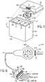
- FIG. 5 is a partial exploded view of the battery 12 in which the cover 62 is removed from the housing 60 of the battery 12 to illustrate an embodiment of the battery management system 50 and the connector 18.
- the connector 18 may be a female pin connector.
- the connector 18 may be a male connector and/or may be a different type of connector.
- the connector 18 includes one or more electrical contacts adapted to electrically couple to a complementary connector (e.g., a male pin connector) to transmit signals and/or power across the connector interface.
- the connector 18 may be adapted to physically and electrically couple to a connector of the state of charge indicator 20.
- the connector 18 may be adapted to physically and electrically couple to a connector of the data input/output tool 112, To enable the physical and electrical coupling to the state of charge indicator 20 and the data input/output tool 112, the connector 18 may include a shape (e.g., dimensions and geometry) and pin configuration that is complementary to a shape and pin configuration of the connector of the state of charge indicator 20 and of the connector of the data input/output tool 112.
- a shape e.g., dimensions and geometry
- pin configuration that is complementary to a shape and pin configuration of the connector of the state of charge indicator 20 and of the connector of the data input/output tool 112.
- the connector 18 may include a proprietary shape and pin configuration.
- the connector 18 may be keyed.
- the proprietary shape and pin configuration may be selected such that the connector 18 does not couple to any connectors other than the state of charge indicator 20 and the data input/output tool 112.
- the connector 18 may include any suitable number of pins (e.g., if the connector 18 is male) or socket contacts (e.g., if the connector 18 is female). In certain embodiments, the connector 18 may include six or seven socket contacts 130.
- the connector 18 may include a first socket contact 130 for data input and a second socket contact 130 for data output, which may be adapted to couple to electrical contacts of the data input/output tool 112 or electrical contacts of the state of charge indicator 20.
- the first socket contact 130 may be used to download data to the memory 106 of the battery management system 50 from the data input/out tool 112.
- the second socket contact 130 may be used to transmit historical data relating to exceptions from the memory 106 to the data input/output tool 112.
- the connector 18 may also include a third socket contact 130 for power input and a fourth socket contact 130 for power output, which may be adapted to couple to electrical contacts of the state of charge indicator 20.
- the connector 18 may include a fifth socket contact 130 and a sixth socket contact 130 to activate one or more indicator lights (e.g., LEDs) of the state of charge indicator 20.
- the state of charge indicator 20 may include two indicator lights, such as a red indicator light and a green indicator light.
- the battery management system 50 may send a signal using the fifth socket contact 130 to activate the green indicator light if the battery management system 50 determines that the state of charge of the battery 12 is above a predetermined threshold.
- the battery management system 50 may send a signal using the sixth socket contact 130 to activate the red indicator light if the battery management system 50 determines that the state of charge of the battery 12 is below a predetermined threshold. The absence of the signals may deactivate the respective indicator light.
- the state of charge indicator may include a third indicator light (e.g., a yellow LED), and the battery management system 50 may send a signal over an additional socket contact to activate the yellow indicator light if the battery management system 50 determines that the state of charge of the battery is within a predetermined threshold range.
- the battery management system 50 may send a binary signal (e.g., a two-bit or three-bit binary signal) using the fifth socket contact 160 (or any other suitable socket contact) to selectively activate the indicator lights of the state of charge indicator 20 (e.g., a red, green, and/or yellow indicator light).
- the battery management system 50 may send a first binary signal (e.g., 001) to selectively activate a green indicator of the state of charge indicator 20, a second binary signal (e.g., 010) to selectively activate a yellow indicator of the state of charge indicator 20, and a third binary signal (e.g., 100) to selectively activate a red indicator of the state of charge indicator 20.
- the battery management system 50 may send a power signal via the sixth socket contact 130 (or any other suitable socket contact) to power the selectively activated indicator light of the state of charge indicator 20.
- the connector 18 may include a seventh socket contact 130 adapted to receive a sleep mode signal from the state of charge indicator 20.
- the connector 18 may include additional socket contacts 130 for data input, data output, indicator light control, or any other signals.
- an additional socket contact may be used to transmit usage data from the memory 106 to the data input/output tool 112.
- the connector 18 may conform to a connection standard that provides a high intrusion protection rating.
- the shape of the connector 18 and position of the connector 18 may protect the socket contacts from moisture, dirt, and debris.
- the connector 18 may be recessed in the cover 62 of the battery 12 such that the cover 62 extends past the connector 18 and minimizes exposure to the connector 18.
- the connector 18 may be disposed about a side wall 132 of the cover 62. While the connector 18 may be disposed in other locations of the cover 62, it may be advantageous to position the connector 18 on a side portion of the cover 62 to further minimize exposure of the connector 18 to moisture, dirt, and debris that may contact the top of the battery cover 62.
- the connector 18 is electrically coupled to the battery management system 50 via one or more leads 134.
- the battery management system 50 may be disposed between the battery cells 54 and the cover 62 of the battery 12.
- the battery management system 50 may be disposed on a support 136, which may be coupled to the housing 60 and/or the cover 62.
- the support 136 may include a plurality of attachment features 138 (e.g., screws) to couple the support 136 to the housing 60 and/or the cover 62.
- the support 136 may couple to side walls 140 of the housing 60.
- the support 136 may couple to top portions 142 of the side walls 140.
- the battery management system 50 is located a distance away from the battery cells 54 such that the battery management system 50 does not contact the battery cells 54. Disposing the battery management system 50 at a distance away from the battery cells 54 may be advantageous to protect the battery management system 50 from possible electrolyte leakage, overheating, or pressure.
- the support 136 and the battery management system 50 may be disposed in an interior chamber just under the cover 62 that is formed by the top wall 140 and side walls 132 of the cover 62. In such embodiments, the support 136 may be secured to the cover 62 or secured to the housing 60 and adapted to extend past the side walls 140 of the housing 60. In other embodiments, the support 136 may be integral with the housing 60 or the cover 62. However, the battery management system 50 may be removable from the battery 12.
- FIG. 6 is a perspective view of an embodiment of an exemplary state of charge indicator 20 including a connector 160 (e.g., a multi-conductor connector) adapted to couple to the connector 18 of the battery 12.
- the connector 160 may be removably coupled (e.g., toollessly removably coupled) to the connector 18 of the battery 12.
- the state of charge indicator 20 may be coupled to the connector 160 via the lead 22.
- the lead 22 may increase the accessibility of the state of charge indicator 20.
- the lead 22 may be any suitable length.
- the length of the lead 22 may be between approximately one foot and five feet or between approximately two feet and four feet. In one embodiment, the length of the lead 22 may be approximately three feet.
- the connector 160 may be a male pin connector. However, it should be noted that in other embodiments, the connector 160 may be a female connector and/or may be a different type of connector.
- the connector 160 may include one or more electrical contacts adapted to electrically couple to the connector 18 to transmit signals and/or power across the connector interface. Accordingly, the connector 160 may include a shape (e.g., dimensions and geometry) and pin configuration that is complementary to the shape and pin configuration of the connector 18 of the battery 12. In some embodiments, the connector 160 may include a proprietary shape and pin configuration, such as one with a high intrusion protection rating.
- the connector 160 may include any suitable number of pins (e.g., if the connector 160 is male) or socket contacts (e.g., if the connector 160 is female). In certain embodiments, the connector 160 may include six, seven, or eight pins. For example, the connector 160 may include pins for power input, power output, data input, data output, control of indicator lights, and control of a sleep mode switch in the battery 12. Furthermore, it should be noted that in some embodiments, the connector 18 of the battery 12 may include more electrical contacts than the connector 160. For example, the connector 18 may include electrical contacts that are adapted to couple to the data input/output tool 112 and are not adapted to couple to the connector 160. However, the connector 160 may still fit entirely over the connector 18 of the battery 12.
- the connector 160 may include a first pin 164 for power input, which may be adapted to transmit power from the battery 12 to the state of charge indicator 20.
- the state of charge indicator 20 may be adapted to operate using power from the battery 12.
- the state of charge indicator 20 may include one or more indicator lights, which may use power from the battery 12.
- the state of charge indicator 20 includes a first indicator light 166, a second indicator light 168, and a third indicator light 170.
- the indicator lights may be LEDs, LCDs, organic LEDs, etc.
- the first indicator light 166 may a red LED to provide an indication that the state of charge of the battery 12 is low (e.g., less than 10% charged).
- the state of charge indicator 20 may include a graphic, such as the letter "E", proximate to the first indicator light 166 to provide a further indication that the first indicator light 166 represents a low state of charge.
- the second indicator light may be a yellow or orange LED to provide an indication that the state of charge of the battery is deleted (e.g., between 10% and 50% charged).
- the third indicator light 170 may be a green LED to provide an indication that the battery is mostly charged (e.g., at least 50% charged).
- the state of charge indicator 20 may also include a graphic such as the letter "F”, proximate to the third indicator light 170 to provide a further indication that the third indicator light represents a full state of charge. It should be noted that the state of charge percentages associated with the indicator lights are merely provided as examples and may vary in other embodiments. Further, in some embodiments, the state of charge indicator 20 may feature two indicator lights instead of three.
- the indicator lights may be activated by the battery management system 50 using binary control.
- the battery management system 50 may transmit a signal to the state of charge indicator over a second pin 172 of the connector 160 to selectively activate the first indicator light 166, the second indicator light 168, or the third indicator light 170.
- the battery management system 50 may transmit a first signal (e.g., 001) to selectively activate the first indicator light 166, a second binary signal (e.g., 010) to selectively activate the second indicator light 168, and a third binary signal (e.g., 100) to selectively activate the third indicator light 170.
- the battery management system 50 may transmit a power signal over three pins to activate the indicator light associated with the respective pin. For example, as noted above, the battery management system 50 may transmit a power signal over a first pin to activate the first indicator light 166, a power signal over a second pin to activate the second indicator light 168, and a power signal over a third pin to activate the third indicator light 170. As noted above, the absence of the power signals may deactivate the respective indicator light.
- the state of charge indicator 20 may be adapted to provide a numerical indication of the state of charge, a segmented display in which each segment represents a percentage of the state of charge, a single indicator (e.g., an LED or graphic) to provide an indication of a low state of charge, or any other suitable state of charge indication.
- the state of charge indicator 20 may also be adapted to provide information relating to other operational parameters of the battery, such as temperature, voltage, and/or current, information relating to the health of the battery, and/or an indication of whether the battery 12 is receiving charge.
- the state of charge indicator 20 interfaces between the battery management system 50 and the charger/maintainer 24. As such, the state of charge indicator 20 functions as an entry point for the charging system. As illustrated, the state of charge indicator 20 includes a second connector 174 (e.g., a multi-conductor connector) for coupling to the charger/maintainer 24.
- the second connector 174 may be directly coupled the body of the state of charge indicator 20, as illustrated, or may be coupled to the state of charge indicator 20 via a lead.
- the connector 174 may be any suitable connector, such as a male pin connector, female pin connector, etc.
- the connector 174 may include a first pin 176 and a second pin 178 adapted to receive power from the charger/maintainer 24.
- the connector 160 may include a third pin 180 and a fourth pin 182 for charging the battery 12.
- the battery management system 50 may be adapted to transmit data (e.g., state of charge data) to the charger/maintainer 24 via the state of charge indicator 20, which may be used by the charger/maintainer 24 to control the delivery of charge to the battery 12,
- the connector 160 may include a fifth pin 184 adapted for data input to receive the data from the battery management system 50
- the connector 178 may include an additional pin adapted for data output to transmit the received data to the charger/maintainer 24.
- the state of charge indicator may not be configured to transmit data from the battery management system 50 to the charger/maintainer 24 and, thus, may not include the fifth pin 184 and the additional pin to facilitate data transfer to the charger/maintainer 24.
- the connector 160 may include a seventh pin 186 configured to transmit a signal to the battery management system 50 to control a switch (e.g., a solid state switch) to disconnect the battery 12 from the vehicle and force the battery 12 into a sleep mode.
- a signal may be transmitted from the state of charge indicator 20 to the battery management system 50 in response to the manual depression of a reset button 190 of the state of charge indicator 20.
- the reset button 190 may function as an antitheft device by disconnecting the battery 12 from the vehicle 14.
- a signal may be transmitted from the state of charge indicator 20 to the battery management system 50 after the reset button 190 has been depressed for a predetermined amount of time.
- the state of charge indicator 20 may be adapted to send the signal after the reset button 190 has been depressed for 2 seconds, 3 seconds, 4 seconds, 5 seconds, or any other suitable amount of time,
- the reset button 190 may also function to reactivate the battery 12. For example, depression of the reset button 190, when the battery is in the sleep mode, may cause the state of charge indicator 20 to transmit a signal to the battery management system 50 to control the switch to reconnect the battery 12 to the vehicle 14.
- the reactivation signal may be transmitted from the state of charge indicator 20 to the battery management system 50 after the reset button 190 has been depressed for a predetermined amount of time.
- the predetermined amount of time may be the same as or different from the predetermined amount of time to disconnect the battery 12 from the vehicle.
- the state of charge indicator 20 may be adapted to send the reactivation signal after the reset button 190 has been depressed for 2 seconds, 3 seconds, 4 seconds, 5 seconds, or any other suitable amount of time.
- the reset button 190 may be a slide switch or an on/off lever that may be adapted to move between an on state and an off state.
- the state of charge indicator 20 may be adapted to transmit a signal to the battery management system 50 immediately following the translation of the switch or lever from an on state to an off state, or vice versa, or may be adapted to transmit the signal after a predetermined amount of time.
- the reset button 190 may be disposed about any suitable location of the state of charge indicator 20.
- FIG. 7 is a flow chart depicting exemplary logic 200 executed by the battery management system 50 for sleep mode control of the battery 12.
- the battery management system 50 may be configured to monitor the battery 12 to determine whether the battery 12 should be placed into a sleep mode to protect the battery 12.
- the battery management system 50 may be adapted to analyze one or more operational parameters of the battery 12 to prevent over-discharge (e.g., under-voltage), over-voltage (e.g., during charging), over-current (e.g., during charging), over-temperature, or any other undesirable battery conditions.
- the battery management system 50 may be configured to place the battery 12 into a sleep mode in response to a user input.
- the battery management system 50 may monitor one or more received signals (block 202).
- the one or more received signals may be signals from one or more sensors disposed in the battery 12.
- the received signals may be generated by the voltmeter 90 for each battery cell 54, the thermocouple 96 for each battery cell 54, the ammeter 98 for each battery cell 54, the voltmeter 100 of the battery management system 50, the ammeter 102 of the battery management system 50, the thermocouple 104 of the battery management system 50, a voltmeter adapted to measure the input voltage from the charger/maintainer 24, an ammeter adapted to measure the input current from the charger/maintainer 24, etc.
- the microprocessor 94 may be configured to compute operational parameters of the battery 12 (e.g., voltage, current, temperature, etc.) based on the signals. Additionally, the battery management system 50 may receive one or more signals from the microprocessor 92 of the measurement device 64 for each battery cell 54, and the signals may include computed operational parameters for the respective battery cell 54. Further, the battery management system 50 may receive signals from the state of charge indicator 20 in response to the depression of the reset button 190.
- operational parameters of the battery 12 e.g., voltage, current, temperature, etc.
- the battery management system 50 may receive one or more signals from the microprocessor 92 of the measurement device 64 for each battery cell 54, and the signals may include computed operational parameters for the respective battery cell 54. Further, the battery management system 50 may receive signals from the state of charge indicator 20 in response to the depression of the reset button 190.
- the battery management system 50 may be configured to determine whether a user input to place the battery 12 into a sleep mode has been received. For example, if the battery 12 is active and connected to the vehicle 14, and the battery management system 50 receives a signal from the state of charge connector 20 (e.g., transmitted over the seventh pin 186), the battery management system 50 may determine that a user input to place the battery 12 into the sleep mode has been received. Accordingly, in response to the user input, the battery management system 50 may force the battery 12 into sleep mode (block 206).
- the battery management system 50 may electronically control the opening and closing of an internal switch, such as a solid state switch (e.g., a field-effect transistor (FET) or a metal-oxide-semiconductor field-effect transistor (MOSFET)), to place the battery 12 into a sleep mode.
- a solid state switch e.g., a field-effect transistor (FET) or a metal-oxide-semiconductor field-effect transistor (MOSFET)
- FET field-effect transistor
- MOSFET metal-oxide-semiconductor field-effect transistor
- the battery management system 50 may continue to monitor and analyze the received signals to determine whether the battery 12 should be placed into the sleep mode. For example, the battery management system 50 may determine whether the state of charge of the battery 12 is less than a predetermined threshold (block 208). As set forth above, the state of charge of the battery 12 may be determined based on the voltage, current, and/or temperature of the battery 12. Additionally or alternatively, the battery management system 50 may determine whether the depth of discharge of the battery is greater than a predetermined depth of discharge threshold. Furthermore, in certain embodiments, the voltage of the battery may be used as an approximation of the state of charge of the battery.
- the predetermined threshold may be based at least in part upon the parameters of the battery 12 and the minimum charge for starting the vehicle 14. For example, if the vehicle 14 requires at least 11 volts to start, the predetermined threshold may be at least 11 volts, In some embodiments, the predetermined threshold may be approximately 11.3 volts. As such, the battery 12 may have an amount of charge sufficient to start the vehicle 14 and to power the vehicle 14 for a period of time until the battery 12 receives charge from the charger/maintainer 24. If the battery management system 50 determines that the state of charge of the battery 12 is less than the predetermined threshold, the battery management system 50 may force the battery 12 into sleep mode (block 206) to prevent over-discharge (e.g., under-voltage).
- over-discharge e.g., under-voltage
- the battery management system 50 may be adapted to protect the battery 12 during charging. For example, the battery management system 50 may determine whether an input voltage to the battery 12 from the charger/maintainer is greater than a predetermined threshold (block 210). If the battery management system 50 determines that the input voltage to the battery 12 is greater than the predetermined threshold, the battery management system 50 may force the battery 12 into sleep mode (block 206) to prevent input over-voltage. Similarly, the battery management system 50 may determine whether an input current to the battery 12 from the charger/maintainer is greater than a predetermined threshold (block 212). If the battery management system 50 determines that the input current to the battery 12 is greater than the predetermined threshold, the battery management system 50 may force the battery 12 into sleep mode (block 206) to prevent input over-current. It should be noted that the predetermined thresholds for input voltage and input current may be selected based upon the parameters of the battery 12.
- the battery management system 50 may be configured to monitor the temperature of the battery 12 to prevent overheating, For example, the battery management system 50 may determine whether the temperature of the battery 12 is greater than a predetermined threshold (block 214). As noted above, the temperature of the battery 12 may be determined using the thermocouple 104 and/or the thermocouple 96 of one or more battery cells 54. If the battery management system 50 determines that the temperature of the battery 12 is greater than the predetermined threshold, the battery management system 50 may force the battery 12 into sleep mode (block 206) to prevent overheating, Additionally, the battery management system 50 may determine whether the temperature of the battery 12 and/or the temperature of one or more battery cells 54 of the battery 12 is less than a predetermined threshold (block 216).
- the battery management system 50 may be desirable for the battery management system 50 to monitor the temperature of the battery 12 and/or the temperature of one or more battery cells 54 during charging, because charging the battery 12 when the temperature is below a predetermined temperature may damage the battery cells 54. For example, charging certain lithium batteries when the temperature of the battery is below -17,78 degrees Celsius (zero degrees Fahrenheit) may damage the battery cells. Thus, the battery management system 50 may force the battery into sleep mode (block 206) to prevent damage to the battery cells (e.g., during charging) if the battery management system 50 determines that the temperature is below the predetermined threshold.
- the battery management system 50 may be configured to consider a combination of operating parameters to determine whether to transition the battery 12 to the sleep mode (block 206).
- the battery management system 50 may transition the battery 12 to the sleep mode if two or more operating parameters (e.g., temperature, state of charge, depth of discharge, input voltage, input current, etc.) violate a respective predetermined threshold.
- two or more operating parameters e.g., temperature, state of charge, depth of discharge, input voltage, input current, etc.
- the battery management system 50 to may not transition the battery 12 to sleep mode.
- the battery management system 50 may not transition the battery 12 to sleep mode. However, if the battery temperature is 43,33 degrees Celsius (110 degrees Fahrenheit) and the voltage is 14.8 volts, the battery management system 50 may transition the battery to the sleep mode.
- FIG. 8 is a flow chart depicting exemplary logic 230 executed by the battery management system 50 for reactivation of the battery 12.
- the battery management system 50 may receive a signal from the state of charge indicator 20 to reactivate the battery 12 (block 232).
- depressing the reset button 190 of the state of charge indicator 20 may generate a signal that causes the battery management system 50 to alter the state of the internal switch (e.g., from open to closed or vice versa).
- the received signal may cause the battery management system 50 to close the switch and reactivate the battery 12 (block 234).
- a condition may have been detected, such as under-voltage, input over-voltage, input over-current, or over-heating, that caused the battery management system 50 to place the battery 12 into sleep mode.
- This condition may still be present when the battery 12 is reactivated.
- the battery management system 50 may implement the sleep mode control logic 200 to continue to monitor the operational parameters of the battery 12 and protect the battery 12 from undesirable operating conditions after the battery 12 is reactivated.
- the condition e.g., under-voltage, input over-voltage, input over-current, or over-temperature
- the battery management system 50 may place the battery 12 back into the sleep mode to avoid damage to the battery 12.
Landscapes
- Engineering & Computer Science (AREA)
- Manufacturing & Machinery (AREA)
- Chemical & Material Sciences (AREA)
- Chemical Kinetics & Catalysis (AREA)
- Electrochemistry (AREA)
- General Chemical & Material Sciences (AREA)
- Microelectronics & Electronic Packaging (AREA)
- Physics & Mathematics (AREA)
- General Physics & Mathematics (AREA)
- Automation & Control Theory (AREA)
- Secondary Cells (AREA)
- Power Engineering (AREA)
Claims (13)
- Procédé de gestion d'un module de batterie au moyen d'un système de gestion de batterie intégré (50) du module de batterie, comprenant :- la réception de données en rapport avec un ou plusieurs paramètres de fonctionnement du module de batterie ;- la détermination si un premier paramètre de fonctionnement du ou des paramètres de fonctionnement dépasse ou non un premier seuil ; et- le passage du module de batterie d'un mode en fonctionnement à un mode veille en réponse à une détermination que le premier paramètre de fonctionnement dépasse le premier seuil,le passage du module de batterie du mode en fonctionnement au mode veille comprenant la commande d'un commutateur interne du module de batterie pour empêcher la circulation de courant depuis le module de batterie, le procédé comprenant en outre :- la réception d'un signal en provenance d'un indicateur d'état de charge (20) couplé à l'extérieur du module de batterie, l'indicateur d'état de charge (20) étant configuré pour envoyer le signal au module de batterie en réponse à un changement d'état d'un commutateur de réinitialisation (160) disposé sur un boitier de l'indicateur d'état de charge (160) ;- l'ouverture du commutateur interne du module de batterie en réponse au signal reçu si le commutateur interne est fermé ; et- la fermeture du commutateur interne du module de batterie en réponse au signal reçu si le commutateur interne est ouvert.
- Procédé selon la revendication 1,
le premier paramètre de fonctionnement comprenant une température du module de batterie. - Procédé selon la revendication 1 ou 2,
le premier paramètre de fonctionnement comprenant une profondeur de décharge du module de batterie. - Procédé selon l'une des revendications 1 à 3,
le premier paramètre de fonctionnement comprenant un courant d'entrée ou une tension d'entrée reçu(e) par le module de batterie en provenance d'un dispositif de charge. - Procédé selon l'une des revendications 1 à 4, comprenant :- la détermination si un deuxième paramètre de fonctionnement du ou des paramètres de fonctionnement est inférieur à un deuxième seuil ; et- le passage du module de batterie du mode en fonctionnement au mode veille en réponse à une détermination que le deuxième paramètre de fonctionnement est inférieur au deuxième seuil.
- Procédé selon la revendication 5,
le deuxième paramètre de fonctionnement comprenant un état de charge du module de batterie. - Procédé selon l'une des revendications 1 à 6,
la réception de données en rapport avec un ou plusieurs paramètres de fonctionnement du module de batterie comprenant :- la réception d'un signal en provenance d'un capteur (64) disposé dans le module de batterie, le capteur (64) étant configuré pour mesurer un paramètre de fonctionnement du module de batterie ; et- la détermination d'une valeur du paramètre de fonctionnement sur la base au moins en partie du signal. - Procédé selon la revendication 7,
le capteur (64) comprenant un thermocouple, un voltmètre, ou un ampèremètre. - Procédé selon l'une des revendications 1 à 8,
le module de batterie comprenant un agencement (52) de cellules de batterie (54) et la réception de données en rapport avec un ou plusieurs paramètres de fonctionnement du module de batterie comprenant :- la réception d'un signal en provenance d'un capteur (64) disposé dans le module de batterie et associé à une cellule de batterie de l'agencement (52), le capteur (64) étant configuré pour mesurer un paramètre de fonctionnement de la cellule de batterie ; et- la détermination d'une valeur du paramètre de fonctionnement sur la base d'au moins en partie le signal. - Procédé selon l'une des revendications 1 à 9,
le module de batterie comprenant un agencement (52) de cellules de batterie (54) et la réception de données en rapport avec un ou plusieurs paramètres de fonctionnement du module de batterie comprenant :- la réception d'un signal en provenance d'un capteur (64) disposé dans le module de batterie et associé à l'agencement (52) de cellules de batterie (54), le capteur (64) étant configuré pour mesurer un paramètre de fonctionnement de l'agencement (52) de cellules de batterie (54) ; et- la détermination d'une valeur du paramètre de fonctionnement sur la base au moins en partie du signal. - Procédé selon l'une des revendications 1 à 10,
la détermination si un premier paramètre de fonctionnement du ou des paramètres de mode de fonctionnement est plus grand ou non qu'un premier seuil comprenant :- l'accès à une mémoire du module de batterie pour déterminer le premier seuil ; et la comparaison du premier paramètre de fonctionnement au premier seuil. - Procédé selon l'une des revendications 1 à 11, l'ouverture du commutateur interne de la batterie si le commutateur interne est fermé correspondant au passage du module de batterie du mode en fonctionnement au mode veille.
- Procédé selon l'une des revendications 1 à 12,
la fermeture du commutateur interne du module de batterie en réponse au signal reçu si le commutateur interne est ouvert correspondant au passage du module de batterie du mode veille au mode en fonctionnement.
Applications Claiming Priority (2)
| Application Number | Priority Date | Filing Date | Title |
|---|---|---|---|
| US14/266,587 US9692240B2 (en) | 2014-04-30 | 2014-04-30 | Battery sleep mode management method and system |
| PCT/US2015/026999 WO2015167889A1 (fr) | 2014-04-30 | 2015-04-22 | Système et procédé de gestion de mode veille de batterie |
Publications (2)
| Publication Number | Publication Date |
|---|---|
| EP3137916A1 EP3137916A1 (fr) | 2017-03-08 |
| EP3137916B1 true EP3137916B1 (fr) | 2022-11-02 |
Family
ID=53189168
Family Applications (1)
| Application Number | Title | Priority Date | Filing Date |
|---|---|---|---|
| EP15723351.1A Active EP3137916B1 (fr) | 2014-04-30 | 2015-04-22 | Procédé de gestion de mode veille de batterie |
Country Status (4)
| Country | Link |
|---|---|
| US (1) | US9692240B2 (fr) |
| EP (1) | EP3137916B1 (fr) |
| CN (1) | CN106663843B (fr) |
| WO (1) | WO2015167889A1 (fr) |
Families Citing this family (13)
| Publication number | Priority date | Publication date | Assignee | Title |
|---|---|---|---|---|
| JP5850017B2 (ja) * | 2013-10-15 | 2016-02-03 | 株式会社デンソー | バッテリ監視装置 |
| EP3297087B1 (fr) * | 2016-09-16 | 2019-10-30 | Kabushiki Kaisha Toshiba | Capuchon de commutateur supprimant la consommation d'énergie d'une batterie secondaire |
| DE102016225691A1 (de) * | 2016-12-20 | 2018-06-21 | Bayerische Motoren Werke Aktiengesellschaft | Hochvolt-Batterie für ein Kraftfahrzeug, insbesondere für einen Kraftwagen |
| US10322688B2 (en) * | 2016-12-30 | 2019-06-18 | Textron Innovations Inc. | Controlling electrical access to a lithium battery on a utility vehicle |
| US10394251B2 (en) * | 2017-04-21 | 2019-08-27 | Ford Global Technologies, Llc | Cloud-based connectivity energy budget manager |
| DE102017127081B4 (de) * | 2017-11-17 | 2019-05-29 | Sma Solar Technology Ag | Verfahren zum Schwarzstart einer Energieversorgungseinrichtung, bidirektionaler Wechselrichter und Energieversorgungseinrichtung mit einem bidirektionalen Wechselrichter |
| CN108627773B (zh) * | 2018-05-04 | 2022-05-24 | 深圳市道通智能航空技术股份有限公司 | 电池功耗控制方法、装置及无人飞行器 |
| IT201800007574A1 (it) * | 2018-07-27 | 2020-01-27 | Gml Srl | Dispositivo di monitoraggio dei parametri di un accumulatore. |
| CN113169388A (zh) * | 2018-12-04 | 2021-07-23 | 松下知识产权经营株式会社 | 电池组、电源系统 |
| US10992797B2 (en) * | 2019-06-21 | 2021-04-27 | Tile, Inc. | Tracking functionality standby mode for third party electronic devices |
| KR20210087816A (ko) * | 2020-01-03 | 2021-07-13 | 주식회사 엘지에너지솔루션 | 배터리 관리 장치 |
| JP2023547250A (ja) * | 2021-09-07 | 2023-11-09 | 寧徳時代新能源科技股▲分▼有限公司 | 過放電保護方法及びシステム、車両、電池管理システム並びに記憶媒体 |
| CN117134470B (zh) * | 2023-10-26 | 2024-02-13 | 珠海市嘉德电能科技有限公司 | Bms电池管理系统的休眠控制方法及相关装置 |
Citations (4)
| Publication number | Priority date | Publication date | Assignee | Title |
|---|---|---|---|---|
| US20020089318A1 (en) * | 2001-01-05 | 2002-07-11 | Dallas Semiconductor Corporation | System and method for performing power control using battery safety protection |
| US20100141216A1 (en) * | 2008-12-05 | 2010-06-10 | Hong Fu Jin Pricision Industry (Shenzhen) Co., Ltd. | Battery system and protection apparatus thereof |
| US20120013189A1 (en) * | 2010-07-15 | 2012-01-19 | Vercingetorix, Llc | battery management system |
| WO2013147070A1 (fr) * | 2012-03-29 | 2013-10-03 | 日本電気株式会社 | Dispositif à semi-conducteurs, procédé permettant de commander l'alimentation électrique d'un dispositif à semi-conducteurs et nœud de capteur |
Family Cites Families (41)
| Publication number | Priority date | Publication date | Assignee | Title |
|---|---|---|---|---|
| US5444378A (en) | 1988-07-13 | 1995-08-22 | Electronic Development Inc. | Battery state of charge monitor |
| GB2245781A (en) | 1990-06-29 | 1992-01-08 | Wu Ko Lee | A device for controlling charging of a battery and displaying charge level |
| DE4131981A1 (de) | 1991-09-26 | 1993-04-01 | Braun Ag | Batteriebetriebenes geraet |
| US6002240A (en) | 1997-12-12 | 1999-12-14 | Dell Usa, L.P. | Self heating of batteries at low temperatures |
| DE10039472A1 (de) | 2000-08-12 | 2002-02-21 | Bosch Gmbh Robert | Schaltungsanordnung zur Überwachung des Ladezustands eines Akkumulators |
| EP1202457B1 (fr) | 2000-10-30 | 2003-08-06 | Sony International (Europe) GmbH | Procédé et logiciel de mise hors circuit de dispositifs électroniques alimentés par batterie et téléphone mobile ainsi équipé |
| US20050038614A1 (en) | 2001-11-27 | 2005-02-17 | Steve Botts | Remote battery monitoring systems and sensors |
| US6794245B2 (en) | 2002-07-18 | 2004-09-21 | Micron Technology, Inc. | Methods of fabricating double-sided hemispherical silicon grain electrodes and capacitor modules |
| GB2397656A (en) | 2003-01-21 | 2004-07-28 | Intelligent Battery Technology | Battery monitoring system |
| US20040189256A1 (en) | 2003-02-14 | 2004-09-30 | Alcatel | Reusable state of charge indicator |
| JP4740409B2 (ja) | 2003-06-11 | 2011-08-03 | 株式会社日立製作所 | 電気自動車或いはハイブリット自動車用リチウム二次電池 |
| CN100521362C (zh) | 2004-11-30 | 2009-07-29 | 新神户电机株式会社 | 蓄电池单元 |
| GB0502274D0 (en) | 2005-02-04 | 2005-03-09 | Xipower Ltd | Battery management system |
| JP4455461B2 (ja) * | 2005-09-12 | 2010-04-21 | 株式会社東芝 | 蓄電システム |
| JP4370297B2 (ja) | 2005-11-25 | 2009-11-25 | 矢崎総業株式会社 | バッテリの管理装置 |
| CN100490274C (zh) * | 2006-05-31 | 2009-05-20 | 北京启润世纪电子技术有限公司 | 蓄电池充放电集成管理器及其管理方法 |
| US8202653B2 (en) | 2006-10-23 | 2012-06-19 | Axion Power International, Inc. | Electrode with reduced resistance grid and hybrid energy storage device having same |
| WO2008051885A1 (fr) | 2006-10-23 | 2008-05-02 | Axion Power International, Inc. | Électrode négative pour un dispositif de stockage d'énergie hybride |
| US7881042B2 (en) | 2006-10-26 | 2011-02-01 | Axion Power International, Inc. | Cell assembly for an energy storage device with activated carbon electrodes |
| JP2008154323A (ja) | 2006-12-14 | 2008-07-03 | Gs Yuasa Corporation:Kk | 充電装置及び充電状態検出方法 |
| US8297198B2 (en) | 2007-05-29 | 2012-10-30 | The United States Of America, As Represented By The Administrator Of The U.S. Environmental Protection Agency | Hydraulic-electric regenerative energy storage system |
| US20090103242A1 (en) | 2007-10-19 | 2009-04-23 | Axion Power International, Inc. | Electrode with Reduced Resistance Grid and Hybrid Energy Storage Device Having Same |
| WO2009063838A1 (fr) | 2007-11-12 | 2009-05-22 | Gs Yuasa Corporation | Matériau actif pour batterie rechargeable au lithium, batterie rechargeable au lithium et son procédé de fabrication |
| US20090195074A1 (en) | 2008-01-31 | 2009-08-06 | Buiel Edward R | Power supply and storage device for improving drilling rig operating efficiency |
| JP5169491B2 (ja) | 2008-05-28 | 2013-03-27 | 株式会社Gsユアサ | 組電池監視装置及び組電池用配線の断線検出方法 |
| US20090312885A1 (en) | 2008-06-11 | 2009-12-17 | Buiel Edward R | Management system for drilling rig power supply and storage system |
| US20100026915A1 (en) | 2008-06-23 | 2010-02-04 | Atico International, Inc. | Digital photoalbum |
| US8232005B2 (en) | 2008-11-17 | 2012-07-31 | Eliot Gerber | Lead acid battery with titanium core grids and carbon based grids |
| US9013142B2 (en) * | 2009-04-27 | 2015-04-21 | Toyota Jidosha Kabushiki Kaisha | Charging connector and charging cable unit |
| JP5493616B2 (ja) | 2009-09-10 | 2014-05-14 | 株式会社Gsユアサ | 電池パック |
| US20110293987A1 (en) | 2010-05-25 | 2011-12-01 | Steven Tartaglia | Battery terminal connection system |
| US8486560B2 (en) | 2010-05-25 | 2013-07-16 | Steven Tartaglia | Battery pack thermal protection from heat sterilization |
| US20110293980A1 (en) | 2010-05-25 | 2011-12-01 | Steven Tartaglia | Battery cushion and insulator |
| US20120149258A1 (en) | 2010-08-03 | 2012-06-14 | Steven Tartaglia | System, method and apparatus for connecting battery cells |
| US20120031645A1 (en) | 2010-08-03 | 2012-02-09 | Steven Tartaglia | System, method and apparatus for connecting battery cells |
| US20120249052A1 (en) * | 2010-10-29 | 2012-10-04 | Sendyne Corporation | Charge redistribution method for cell arrays |
| US20120225331A1 (en) | 2011-03-02 | 2012-09-06 | Lithionics, Llc | Battery pack protection system |
| US20120244399A1 (en) | 2011-03-24 | 2012-09-27 | Lithionics, Llc | Battery pack thermal vent protection |
| CN102761148B (zh) * | 2011-04-29 | 2015-08-26 | 比亚迪股份有限公司 | 一种电池组管理系统 |
| DE102011115908A1 (de) | 2011-10-14 | 2013-04-18 | Bmz Batterien-Montage-Zentrum Gmbh | Schaltungsordnung und Verfahren für Zellenmanagement in einer mobilen Anwendung |
| CN102638081B (zh) * | 2012-05-04 | 2014-05-07 | 天津凌可机电设计有限公司 | 智能矩阵电池充放电管理系统及管理方法 |
-
2014
- 2014-04-30 US US14/266,587 patent/US9692240B2/en active Active
-
2015
- 2015-04-22 CN CN201580023019.0A patent/CN106663843B/zh active Active
- 2015-04-22 EP EP15723351.1A patent/EP3137916B1/fr active Active
- 2015-04-22 WO PCT/US2015/026999 patent/WO2015167889A1/fr active Application Filing
Patent Citations (5)
| Publication number | Priority date | Publication date | Assignee | Title |
|---|---|---|---|---|
| US20020089318A1 (en) * | 2001-01-05 | 2002-07-11 | Dallas Semiconductor Corporation | System and method for performing power control using battery safety protection |
| US20100141216A1 (en) * | 2008-12-05 | 2010-06-10 | Hong Fu Jin Pricision Industry (Shenzhen) Co., Ltd. | Battery system and protection apparatus thereof |
| US20120013189A1 (en) * | 2010-07-15 | 2012-01-19 | Vercingetorix, Llc | battery management system |
| WO2013147070A1 (fr) * | 2012-03-29 | 2013-10-03 | 日本電気株式会社 | Dispositif à semi-conducteurs, procédé permettant de commander l'alimentation électrique d'un dispositif à semi-conducteurs et nœud de capteur |
| US20150048680A1 (en) * | 2012-03-29 | 2015-02-19 | Nec Corporation | Semiconductor device, power supply control method of semiconductor device, and sensor node |
Also Published As
| Publication number | Publication date |
|---|---|
| CN106663843A (zh) | 2017-05-10 |
| US20150318723A1 (en) | 2015-11-05 |
| WO2015167889A1 (fr) | 2015-11-05 |
| US9692240B2 (en) | 2017-06-27 |
| EP3137916A1 (fr) | 2017-03-08 |
| CN106663843B (zh) | 2022-06-21 |
Similar Documents
| Publication | Publication Date | Title |
|---|---|---|
| US10622682B2 (en) | System and method for placing a battery into a sleep mode | |
| EP3138142B1 (fr) | Construction de batterie pour intégration de système de gestion de batterie | |
| EP3137916B1 (fr) | Procédé de gestion de mode veille de batterie | |
| EP3138141B1 (fr) | Système et procédé de gestion de batterie intégrés | |
| US8093862B2 (en) | Systems, apparatus and methods for battery charge management | |
| US10090498B2 (en) | Modular battery pack apparatus, systems, and methods including viral data and/or code transfer | |
| CN107123834A (zh) | 具有集成电池管理系统的电池组 | |
| CN106899052A (zh) | 具有隔离、分布式、菊花链式电池模块控制器的电池管理系统(bms) | |
| EP0944153A2 (fr) | Système de charge d'outil électrique comprennant un indicateur de niveau de charge et des fonctions de commande de charge | |
| US20030038611A1 (en) | Rechargeable batteries | |
| KR101663579B1 (ko) | 배터리 모니터링 장치 및 이를 이용한 배터리 모니터링 시스템 | |
| EP2724391A2 (fr) | Appareil, systèmes et procédés de bloc de batteries modulaire | |
| KR20130101235A (ko) | 에너지를 재사용하는 배터리 밸런싱 시스템 및 배터리 밸런싱 방법 | |
| JP2013236492A (ja) | 電池モジュール、及び電池管理システム | |
| US20060091854A1 (en) | Power monitoring and balancing device | |
| KR101923515B1 (ko) | 에너지 저장 시스템의 안정화 및 효율적 관리를 위하여 배터리의 상태를 주기적으로 모니터링 및 제어하는 시스템 |
Legal Events
| Date | Code | Title | Description |
|---|---|---|---|
| STAA | Information on the status of an ep patent application or granted ep patent |
Free format text: STATUS: THE INTERNATIONAL PUBLICATION HAS BEEN MADE |
|
| PUAI | Public reference made under article 153(3) epc to a published international application that has entered the european phase |
Free format text: ORIGINAL CODE: 0009012 |
|
| STAA | Information on the status of an ep patent application or granted ep patent |
Free format text: STATUS: REQUEST FOR EXAMINATION WAS MADE |
|
| 17P | Request for examination filed |
Effective date: 20161028 |
|
| AK | Designated contracting states |
Kind code of ref document: A1 Designated state(s): AL AT BE BG CH CY CZ DE DK EE ES FI FR GB GR HR HU IE IS IT LI LT LU LV MC MK MT NL NO PL PT RO RS SE SI SK SM TR |
|
| AX | Request for extension of the european patent |
Extension state: BA ME |
|
| DAV | Request for validation of the european patent (deleted) | ||
| DAX | Request for extension of the european patent (deleted) | ||
| RAP1 | Party data changed (applicant data changed or rights of an application transferred) |
Owner name: JOHNSON CONTROLS TECHNOLOGY COMPANY |
|
| STAA | Information on the status of an ep patent application or granted ep patent |
Free format text: STATUS: EXAMINATION IS IN PROGRESS |
|
| 17Q | First examination report despatched |
Effective date: 20190603 |
|
| RAP1 | Party data changed (applicant data changed or rights of an application transferred) |
Owner name: CPS TECHNOLOGY HOLDINGS LLC |
|
| STAA | Information on the status of an ep patent application or granted ep patent |
Free format text: STATUS: EXAMINATION IS IN PROGRESS |
|
| STAA | Information on the status of an ep patent application or granted ep patent |
Free format text: STATUS: EXAMINATION IS IN PROGRESS |
|
| REG | Reference to a national code |
Ref country code: DE Ref legal event code: R079 Ref document number: 602015081409 Country of ref document: DE Free format text: PREVIOUS MAIN CLASS: G01R0031360000 Ipc: H01M0010420000 |
|
| GRAP | Despatch of communication of intention to grant a patent |
Free format text: ORIGINAL CODE: EPIDOSNIGR1 |
|
| STAA | Information on the status of an ep patent application or granted ep patent |
Free format text: STATUS: GRANT OF PATENT IS INTENDED |
|
| RIC1 | Information provided on ipc code assigned before grant |
Ipc: H01M 10/48 20060101ALI20220501BHEP Ipc: H01M 10/42 20060101AFI20220501BHEP |
|
| INTG | Intention to grant announced |
Effective date: 20220523 |
|
| GRAS | Grant fee paid |
Free format text: ORIGINAL CODE: EPIDOSNIGR3 |
|
| GRAA | (expected) grant |
Free format text: ORIGINAL CODE: 0009210 |
|
| STAA | Information on the status of an ep patent application or granted ep patent |
Free format text: STATUS: THE PATENT HAS BEEN GRANTED |
|
| AK | Designated contracting states |
Kind code of ref document: B1 Designated state(s): AL AT BE BG CH CY CZ DE DK EE ES FI FR GB GR HR HU IE IS IT LI LT LU LV MC MK MT NL NO PL PT RO RS SE SI SK SM TR |
|
| REG | Reference to a national code |
Ref country code: GB Ref legal event code: FG4D |
|
| REG | Reference to a national code |
Ref country code: CH Ref legal event code: EP Ref country code: AT Ref legal event code: REF Ref document number: 1529430 Country of ref document: AT Kind code of ref document: T Effective date: 20221115 |
|
| REG | Reference to a national code |
Ref country code: DE Ref legal event code: R096 Ref document number: 602015081409 Country of ref document: DE |
|
| REG | Reference to a national code |
Ref country code: IE Ref legal event code: FG4D |
|
| REG | Reference to a national code |
Ref country code: LT Ref legal event code: MG9D |
|
| REG | Reference to a national code |
Ref country code: NL Ref legal event code: MP Effective date: 20221102 |
|
| REG | Reference to a national code |
Ref country code: AT Ref legal event code: MK05 Ref document number: 1529430 Country of ref document: AT Kind code of ref document: T Effective date: 20221102 |
|
| PG25 | Lapsed in a contracting state [announced via postgrant information from national office to epo] |
Ref country code: SE Free format text: LAPSE BECAUSE OF FAILURE TO SUBMIT A TRANSLATION OF THE DESCRIPTION OR TO PAY THE FEE WITHIN THE PRESCRIBED TIME-LIMIT Effective date: 20221102 Ref country code: PT Free format text: LAPSE BECAUSE OF FAILURE TO SUBMIT A TRANSLATION OF THE DESCRIPTION OR TO PAY THE FEE WITHIN THE PRESCRIBED TIME-LIMIT Effective date: 20230302 Ref country code: NO Free format text: LAPSE BECAUSE OF FAILURE TO SUBMIT A TRANSLATION OF THE DESCRIPTION OR TO PAY THE FEE WITHIN THE PRESCRIBED TIME-LIMIT Effective date: 20230202 Ref country code: LT Free format text: LAPSE BECAUSE OF FAILURE TO SUBMIT A TRANSLATION OF THE DESCRIPTION OR TO PAY THE FEE WITHIN THE PRESCRIBED TIME-LIMIT Effective date: 20221102 Ref country code: FI Free format text: LAPSE BECAUSE OF FAILURE TO SUBMIT A TRANSLATION OF THE DESCRIPTION OR TO PAY THE FEE WITHIN THE PRESCRIBED TIME-LIMIT Effective date: 20221102 Ref country code: ES Free format text: LAPSE BECAUSE OF FAILURE TO SUBMIT A TRANSLATION OF THE DESCRIPTION OR TO PAY THE FEE WITHIN THE PRESCRIBED TIME-LIMIT Effective date: 20221102 Ref country code: AT Free format text: LAPSE BECAUSE OF FAILURE TO SUBMIT A TRANSLATION OF THE DESCRIPTION OR TO PAY THE FEE WITHIN THE PRESCRIBED TIME-LIMIT Effective date: 20221102 |
|
| PG25 | Lapsed in a contracting state [announced via postgrant information from national office to epo] |
Ref country code: RS Free format text: LAPSE BECAUSE OF FAILURE TO SUBMIT A TRANSLATION OF THE DESCRIPTION OR TO PAY THE FEE WITHIN THE PRESCRIBED TIME-LIMIT Effective date: 20221102 Ref country code: PL Free format text: LAPSE BECAUSE OF FAILURE TO SUBMIT A TRANSLATION OF THE DESCRIPTION OR TO PAY THE FEE WITHIN THE PRESCRIBED TIME-LIMIT Effective date: 20221102 Ref country code: LV Free format text: LAPSE BECAUSE OF FAILURE TO SUBMIT A TRANSLATION OF THE DESCRIPTION OR TO PAY THE FEE WITHIN THE PRESCRIBED TIME-LIMIT Effective date: 20221102 Ref country code: IS Free format text: LAPSE BECAUSE OF FAILURE TO SUBMIT A TRANSLATION OF THE DESCRIPTION OR TO PAY THE FEE WITHIN THE PRESCRIBED TIME-LIMIT Effective date: 20230302 Ref country code: HR Free format text: LAPSE BECAUSE OF FAILURE TO SUBMIT A TRANSLATION OF THE DESCRIPTION OR TO PAY THE FEE WITHIN THE PRESCRIBED TIME-LIMIT Effective date: 20221102 Ref country code: GR Free format text: LAPSE BECAUSE OF FAILURE TO SUBMIT A TRANSLATION OF THE DESCRIPTION OR TO PAY THE FEE WITHIN THE PRESCRIBED TIME-LIMIT Effective date: 20230203 |
|
| PG25 | Lapsed in a contracting state [announced via postgrant information from national office to epo] |
Ref country code: NL Free format text: LAPSE BECAUSE OF FAILURE TO SUBMIT A TRANSLATION OF THE DESCRIPTION OR TO PAY THE FEE WITHIN THE PRESCRIBED TIME-LIMIT Effective date: 20221102 |
|
| PG25 | Lapsed in a contracting state [announced via postgrant information from national office to epo] |
Ref country code: SM Free format text: LAPSE BECAUSE OF FAILURE TO SUBMIT A TRANSLATION OF THE DESCRIPTION OR TO PAY THE FEE WITHIN THE PRESCRIBED TIME-LIMIT Effective date: 20221102 Ref country code: RO Free format text: LAPSE BECAUSE OF FAILURE TO SUBMIT A TRANSLATION OF THE DESCRIPTION OR TO PAY THE FEE WITHIN THE PRESCRIBED TIME-LIMIT Effective date: 20221102 Ref country code: EE Free format text: LAPSE BECAUSE OF FAILURE TO SUBMIT A TRANSLATION OF THE DESCRIPTION OR TO PAY THE FEE WITHIN THE PRESCRIBED TIME-LIMIT Effective date: 20221102 Ref country code: DK Free format text: LAPSE BECAUSE OF FAILURE TO SUBMIT A TRANSLATION OF THE DESCRIPTION OR TO PAY THE FEE WITHIN THE PRESCRIBED TIME-LIMIT Effective date: 20221102 Ref country code: CZ Free format text: LAPSE BECAUSE OF FAILURE TO SUBMIT A TRANSLATION OF THE DESCRIPTION OR TO PAY THE FEE WITHIN THE PRESCRIBED TIME-LIMIT Effective date: 20221102 |
|
| PGFP | Annual fee paid to national office [announced via postgrant information from national office to epo] |
Ref country code: FR Payment date: 20230425 Year of fee payment: 9 Ref country code: DE Payment date: 20230427 Year of fee payment: 9 |
|
| REG | Reference to a national code |
Ref country code: DE Ref legal event code: R097 Ref document number: 602015081409 Country of ref document: DE |
|
| PG25 | Lapsed in a contracting state [announced via postgrant information from national office to epo] |
Ref country code: SK Free format text: LAPSE BECAUSE OF FAILURE TO SUBMIT A TRANSLATION OF THE DESCRIPTION OR TO PAY THE FEE WITHIN THE PRESCRIBED TIME-LIMIT Effective date: 20221102 Ref country code: AL Free format text: LAPSE BECAUSE OF FAILURE TO SUBMIT A TRANSLATION OF THE DESCRIPTION OR TO PAY THE FEE WITHIN THE PRESCRIBED TIME-LIMIT Effective date: 20221102 |
|
| PLBE | No opposition filed within time limit |
Free format text: ORIGINAL CODE: 0009261 |
|
| STAA | Information on the status of an ep patent application or granted ep patent |
Free format text: STATUS: NO OPPOSITION FILED WITHIN TIME LIMIT |
|
| 26N | No opposition filed |
Effective date: 20230803 |
|
| PGFP | Annual fee paid to national office [announced via postgrant information from national office to epo] |
Ref country code: GB Payment date: 20230427 Year of fee payment: 9 |
|
| PG25 | Lapsed in a contracting state [announced via postgrant information from national office to epo] |
Ref country code: SI Free format text: LAPSE BECAUSE OF FAILURE TO SUBMIT A TRANSLATION OF THE DESCRIPTION OR TO PAY THE FEE WITHIN THE PRESCRIBED TIME-LIMIT Effective date: 20221102 |
|
| REG | Reference to a national code |
Ref country code: CH Ref legal event code: PL |
|
| PG25 | Lapsed in a contracting state [announced via postgrant information from national office to epo] |
Ref country code: LU Free format text: LAPSE BECAUSE OF NON-PAYMENT OF DUE FEES Effective date: 20230422 |
|
| REG | Reference to a national code |
Ref country code: BE Ref legal event code: MM Effective date: 20230430 |
|
| PG25 | Lapsed in a contracting state [announced via postgrant information from national office to epo] |
Ref country code: MC Free format text: LAPSE BECAUSE OF FAILURE TO SUBMIT A TRANSLATION OF THE DESCRIPTION OR TO PAY THE FEE WITHIN THE PRESCRIBED TIME-LIMIT Effective date: 20221102 |
|
| PG25 | Lapsed in a contracting state [announced via postgrant information from national office to epo] |
Ref country code: MC Free format text: LAPSE BECAUSE OF FAILURE TO SUBMIT A TRANSLATION OF THE DESCRIPTION OR TO PAY THE FEE WITHIN THE PRESCRIBED TIME-LIMIT Effective date: 20221102 Ref country code: LI Free format text: LAPSE BECAUSE OF NON-PAYMENT OF DUE FEES Effective date: 20230430 Ref country code: CH Free format text: LAPSE BECAUSE OF NON-PAYMENT OF DUE FEES Effective date: 20230430 |
|
| REG | Reference to a national code |
Ref country code: IE Ref legal event code: MM4A |
|
| PG25 | Lapsed in a contracting state [announced via postgrant information from national office to epo] |
Ref country code: BE Free format text: LAPSE BECAUSE OF NON-PAYMENT OF DUE FEES Effective date: 20230430 |
|
| PG25 | Lapsed in a contracting state [announced via postgrant information from national office to epo] |
Ref country code: IE Free format text: LAPSE BECAUSE OF NON-PAYMENT OF DUE FEES Effective date: 20230422 |
|
| PG25 | Lapsed in a contracting state [announced via postgrant information from national office to epo] |
Ref country code: IE Free format text: LAPSE BECAUSE OF NON-PAYMENT OF DUE FEES Effective date: 20230422 |