EP3137262B1 - Stapling device - Google Patents
Stapling device Download PDFInfo
- Publication number
- EP3137262B1 EP3137262B1 EP15709635.5A EP15709635A EP3137262B1 EP 3137262 B1 EP3137262 B1 EP 3137262B1 EP 15709635 A EP15709635 A EP 15709635A EP 3137262 B1 EP3137262 B1 EP 3137262B1
- Authority
- EP
- European Patent Office
- Prior art keywords
- leg
- stapling device
- lever
- driver
- bearing
- Prior art date
- Legal status (The legal status is an assumption and is not a legal conclusion. Google has not performed a legal analysis and makes no representation as to the accuracy of the status listed.)
- Active
Links
Images

Classifications
-
- B—PERFORMING OPERATIONS; TRANSPORTING
- B25—HAND TOOLS; PORTABLE POWER-DRIVEN TOOLS; MANIPULATORS
- B25C—HAND-HELD NAILING OR STAPLING TOOLS; MANUALLY OPERATED PORTABLE STAPLING TOOLS
- B25C5/00—Manually operated portable stapling tools; Hand-held power-operated stapling tools; Staple feeding devices therefor
- B25C5/02—Manually operated portable stapling tools; Hand-held power-operated stapling tools; Staple feeding devices therefor with provision for bending the ends of the staples on to the work
- B25C5/0221—Stapling tools of the table model type, i.e. tools supported by a table or the work during operation
- B25C5/0242—Stapling tools of the table model type, i.e. tools supported by a table or the work during operation having a pivoting upper leg and a leg provided with an anvil supported by the table or work
- B25C5/025—Stapling tools of the table model type, i.e. tools supported by a table or the work during operation having a pivoting upper leg and a leg provided with an anvil supported by the table or work the plunger being manually operated
-
- B—PERFORMING OPERATIONS; TRANSPORTING
- B25—HAND TOOLS; PORTABLE POWER-DRIVEN TOOLS; MANIPULATORS
- B25C—HAND-HELD NAILING OR STAPLING TOOLS; MANUALLY OPERATED PORTABLE STAPLING TOOLS
- B25C5/00—Manually operated portable stapling tools; Hand-held power-operated stapling tools; Staple feeding devices therefor
- B25C5/10—Driving means
- B25C5/11—Driving means operated by manual or foot power
Definitions
- the invention relates to a stapler.
- Known stapler devices such as for example DE2534178B1 are known, have a lower part, which has on its underside a footprint for placement on a table top and an extending in a longitudinal direction from a front region to a rear region anvil legs with an anvil plate in the front region.
- a staple magazine is mounted on a bearing block limited pivotally mounted on the lower part, which can be lowered so far in the front area until it rests on the anvil plate or lying on the anvil plate records.
- a driver leg is limited pivotally mounted relative to the lower part and the staple magazine, which carries a driver in the front, which acts when lowering the vordemst located in the staple cartridge staple with force and presses through a gap in the bottom of the staple magazine, so that they on the anvil plate lying documents pierces and is deformed by means of the anvil plate.
- Such prior art staplers are manufactured in different designs and have proven excellent for decades. In order to apply a sufficiently high force when stapling, but it is usually necessary to press as far as possible on the driver's leg when pressed down.
- the invention is based on the idea that by the pivotal mounting of the anvil leg in stationary during stapling immovably held lower part of stitching not necessarily as far forward pressure on the driver leg must be exercised, but that the pressure in the middle or even in the rear area on the Driver legs can be exercised. Furthermore, the force the user has to spend stapling is smaller than most conventional staplers.
- the first bearing with which the at least one lever is mounted in the rear region on the lower part, a pin and a longitudinally extending slot in which the pin is guided. It is possible that the pin is firmly connected to the lower part and the slot is arranged in the lever or vice versa, that the pin is firmly connected to the lever and the slot is arranged in the lower part.
- the second bearing with which the at least one lever is mounted between the front region and the rear region on the anvil limb, is designed as a pivot axis.
- the slot is advantageously closed at its two ends, so that the lever is only limited mobility, by forming the two ends of the slot stops for the pin.
- the lower part expediently has a trough with a bottom and at least one longitudinally extending, upstanding from the bottom side wall, which is provided, depending on the embodiment, either with the pin or with the slot of the first bearing. It is preferred that the trough has two spaced parallel side walls, in particular when two levers are present.
- the tub may be made of sheet metal, wherein it is then advantageously received in a plastic panel and from the outside for the viewer at least for the most part is not visible. But it is also possible that Execute tub as a plastic part in one piece, for example as an injection molded part. If the pin of the first bearing is arranged on the trough, then it can be integrally molded from plastic or attached to the trough as a separate component, for example made of metal.
- the at least one lever is coupled to the driver's leg in such a way that a force transmission element fixedly connected to the one component rests against the other component on a run-on slope inclined relative to the vertical and relative to the horizontal.
- the force transmission element is a rigidly or rotatably mounted on the driver's leg or on the lever role.
- the at least one lever at its front end on the inclined relative to the vertical and relative to the horizontal bevel on which rests firmly connected to the driver's leg power transmission element.
- the ramp relative to the horizontal has such a varying inclination over its length that the force transmission element upon penetration of a staple in stapled, lying on the anvil plate paper and bending over the free ends of a staple on the anvil plate on a Lot with a lower inclination rests as when lowering the staple cartridge and when removing a staple from a recorded in the staple cartridge staple strand.
- This takes into account the fact that a greater force must be applied to the staple when penetrating the paper and bending over the free ends than when lowering the staple cartridge and when removing the staple.
- the at least one lever forks at its front end into an upper and a lower front part, and in a space between the upper and the lower front part of a fixedly connected to the driver leg power transmission element is arranged, which in turn may be a rigid or rotatable attached to the driver leg role.
- This is forcibly guided between the upper and the lower front part, so that a lowering of the front end of the lever also entails a lowering of the driver's leg, while a lifting of the front end of the lever results in a lifting of the driver's leg.
- the stapler has two spaced apart parallel to each other arranged identical lever, each of which is mounted by means of a first bearing on the lower part and by means of a second bearing on the anvil and is coupled with its front end to the driver's leg.
- the two levers are expediently arranged symmetrically with respect to one another with respect to a longitudinal center plane, so that the mounting on the lower part and on the anvil leg as well as the coupling with the driver leg are symmetrical. By arranging two levers, the force in the stapler is distributed more evenly.
- the at least one lever is decoupled with the driver's leg.
- at least one coupling element is present, which is a downward movement of the front end of at least one lever opposes a counter force.
- the coupling elements may be on the magazine upwardly projecting sheet metal extensions, which engage in correspondingly shaped holes on a folded transverse flank of the respective lever.
- each lever is connected by means of a rear end facing the rear region and the second bearing and extending in the direction of the front region tension spring connected to the lower part, so that the tension spring applies the counterforce.
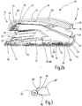
- the stapler 10 shown in the drawing has an elongated shape and extends in a longitudinal direction from a front portion 12 to a rear portion 14. It has a bottom surface 16 on a footprint 18 exhibiting lower part 20, which in turn a trough 22 from Sheet metal with a bottom 24 and at a distance parallel to each other in the longitudinal direction extending from the bottom 24 upstanding side walls 26 and has received in a support surface 18 having plastic cover 28.
- an anvil limb 32 carrying an anvil plate 30 in the front region 12 is pivotably mounted about a first pivot axis 34 in a limited manner.
- the first pivot axis 34 is located further away from the rear region 14 than the anvil plate 30 on a bearing block 36 in the rear region 14 is a staple magazine 38 about a second pivot axis 40 limited pivotally mounted on the anvil leg 32.
- the staple magazine 38 has at its front end 42 on a lower side gap 44 which is disposed above the anvil plate 30 and through which the staple first taken in the staple cartridge 38 staple is performed during the stapling process.
- the first compression spring 54 and the second compression spring are matched to one another so that a lowering of the driver 46 on the foremost staple only occurs when the staple cartridge 38 in the region of the gap 44 already on the anvil plate 30 and on lying on the anvil plate 30 Written material rests.
- a lever 56 is pivotally mounted limited, with the respective side wall 26 at the respective other side wall 26 facing inner surface adjacent in the rear region 14 by means of a first bearing 58 on the respective side wall 26 and is mounted approximately in the middle between the front portion 12 and the rear portion 14 by means of a second bearing 60 on the anvil leg 32.
- Fig. 2a is in the direction of the rear of the two levers 56
- Fig. 2b the front view of the two levers 56 shown in the viewing direction.
- the first bearing 58 is a movable bearing in which a projecting from the respective side wall 26 pin 62 is guided in a closed at its two ends slot 64 in the respective lever 56.
- the second bearing 60 is a third pivot axis 66.
- each of the levers 56 forks into an upper front part 70 and a lower front part 72, between which a gap 74 is free.
- the roller 76 is used to transmit power from the lever 56 to the driver leg 48 and may for this purpose also consist of a different material and be non-rotatably fixed to the driver leg 48 so that it can be referred to as a pin.
- the two levers 56 are with respect to a longitudinal center plane 78, through which the section according to Fig. 2a runs, arranged symmetrically, as well as the rollers 76 and the bearings 58, 60th
- each lever 56 extending in the direction of the front portion 12 tension spring 80 which is attached at its other end to the lower part 20.
- the associated roller 76 is forcibly guided, so that a depression of the cap 50 pivoting of the anvil leg 32 about the first pivot axis 34, a pivoting of the lever 56 about the third pivot axes 66 and finally, even if near the rear region 14 pressure is exerted on the cap 50, a lowering of the driver 46th and due to the interaction of the first compression spring 54 and the second compression spring causes a lowering of the staple cartridge 38 on the anvil plate 30.
- Fig. 3 schematically the front end 68 'of a lever 56' is shown in an alternative embodiment.
- the lever 56 ' has no fork in an upper and lower front section, but a ramp 22, on which the driver leg 48 attached to the roller 76' is applied.
- the run-up slope 82 is inclined both with respect to the vertical and with respect to the horizontal and has a first portion 84, the inclination relative to the horizontal is greater than the inclination of a arranged under the first batch 84, adjoining this second batch 86.
- the invention relates to a stapler 10, which extends in a longitudinal direction from a front portion 12 to a rear portion 14, with a bottom surface 16 having a footing 18 having lower part 20, with a about a first pivot axis 34 in front region 12 relative to the lower part 20 limited pivotally mounted, in the front region 12 an anvil plate 30 supporting anvil legs 32, with a limited to a bearing block 36 in the rear portion 14 about a second pivot axis 40 relative to the anvil leg 32 pivotally mounted staple cartridge 38, with a order the second pivot axis 40 relative to the anvil leg 32 and relative to the staple magazine 38 limited pivotally mounted, a driver 46 for performing staples through a gap 44 at the front end 42 of the staple magazine 38 and for pressing the staples on the anvil plate 30 having Driver leg 48 and at least one extending in the longitudinal direction lever 56, 56 'mounted in the rear region 14 by means of a first bearing 58 on the lower part 20 and between the front portion 12 and the rear portion 14 by means of
Description
Die Erfindung betrifft ein Heftklammergerät.The invention relates to a stapler.
Bekannte Heftklammergeräte, wie zum Beispiel aus
Es ist daher Aufgabe der Erfindung, ein Heftklammergerät zu entwickeln, das einfacher zu handhaben ist.It is therefore an object of the invention to develop a stapler which is easier to handle.
Diese Aufgabe wird erfindungsgemäß durch ein Heftklammergerät mit den Merkmalen des Anspruchs 1 gelöst. Vorteilhafte Weiterbildungen der Erfindung sind Gegenstand der abhängigen Ansprüche.This object is achieved by a stapler with the features of claim 1. Advantageous developments of the invention are the subject of the dependent claims.
Der Erfindung liegt der Gedanke zugrunde, dass durch die schwenkbare Lagerung des Ambossschenkels im beim Heftvorgang ortsfest unbeweglich gehaltenen Unterteil beim Heften nicht zwingend möglichst weit vorne Druck auf den Treiberschenkel ausgeübt werden muss, sondern dass der Druck auch im mittleren oder gar im rückwärtigen Bereich auf den Treiberschenkel ausgeübt werden kann. Desweiteren ist die Kraft, die der Benutzer beim Heften aufwenden muss, kleiner als bei den meisten herkömmlichen Heftgeräten.The invention is based on the idea that by the pivotal mounting of the anvil leg in stationary during stapling immovably held lower part of stitching not necessarily as far forward pressure on the driver leg must be exercised, but that the pressure in the middle or even in the rear area on the Driver legs can be exercised. Furthermore, the force the user has to spend stapling is smaller than most conventional staplers.
Vorteilhaft weist das erste Lager, mit dem der mindestens eine Hebel im rückwärtigen Bereich am Unterteil gelagert ist, einen Zapfen sowie ein sich in der Längsrichtung erstreckendes Langloch auf, in dem der Zapfen geführt ist. Dabei ist es möglich, dass der Zapfen fest mit dem Unterteil verbunden und das Langloch im Hebel angeordnet ist oder umgekehrt, dass der Zapfen fest mit dem Hebel verbunden und das Langloch im Unterteil angeordnet ist. Bei dieser Ausgestaltung des ersten Lagers ist das zweite Lager, mit dem der mindestens eine Hebel zwischen dem vorderen Bereich und dem rückwärtigen Bereich am Ambossschenkel gelagert ist, als Schwenkachse ausgebildet. Das Langloch ist vorteilhaft an seinen beiden Enden geschlossen, so dass der Hebel nur begrenzt beweglich ist, indem die beiden Enden des Langlochs Anschläge für den Zapfen bilden.Advantageously, the first bearing, with which the at least one lever is mounted in the rear region on the lower part, a pin and a longitudinally extending slot in which the pin is guided. It is possible that the pin is firmly connected to the lower part and the slot is arranged in the lever or vice versa, that the pin is firmly connected to the lever and the slot is arranged in the lower part. In this embodiment of the first bearing, the second bearing, with which the at least one lever is mounted between the front region and the rear region on the anvil limb, is designed as a pivot axis. The slot is advantageously closed at its two ends, so that the lever is only limited mobility, by forming the two ends of the slot stops for the pin.
Das Unterteil weist zweckmäßig eine Wanne mit einem Boden und mindestens einer sich in Längsrichtung erstreckenden, vom Boden hochstehenden Seitenwand auf, welche, je nach Ausführungsbeispiel, entweder mit dem Zapfen oder mit dem Langloch des ersten Lagers versehen ist. Es wird bevorzugt, dass die Wanne zwei im Abstand parallel zueinander verlaufende Seitenwände aufweist, insbesondere dann, wenn zwei Hebel vorhanden sind. Die Wanne kann aus Blech gefertigt sein, wobei sie dann vorteilhaft in einer Kunststoffverkleidung aufgenommen und von außen für den Betrachter zumindest größtenteils nicht sichtbar ist. Es ist aber auch möglich, die Wanne als Kunststoffteil einstückig auszuführen, beispielsweise als Spritzgussteil. Ist der Zapfen des ersten Lagers an der Wanne angeordnet, so kann er einstückig aus Kunststoff angeformt sein oder als separates Bauteil, beispielsweise aus Metall, an der Wanne befestigt sein.The lower part expediently has a trough with a bottom and at least one longitudinally extending, upstanding from the bottom side wall, which is provided, depending on the embodiment, either with the pin or with the slot of the first bearing. It is preferred that the trough has two spaced parallel side walls, in particular when two levers are present. The tub may be made of sheet metal, wherein it is then advantageously received in a plastic panel and from the outside for the viewer at least for the most part is not visible. But it is also possible that Execute tub as a plastic part in one piece, for example as an injection molded part. If the pin of the first bearing is arranged on the trough, then it can be integrally molded from plastic or attached to the trough as a separate component, for example made of metal.
Gemäß einem ersten Ausführungsbeispiel ist der mindestens eine Hebel derart mit dem Treiberschenkel gekoppelt, dass ein fest mit dem einen Bauteil verbundenes Kraftübertragungselement an einer gegenüber der Vertikalen und gegenüber der Horizontalen geneigten Auflaufschräge am anderen Bauteil anliegt. Dabei wird bevorzugt, dass das Kraftübertragungselement eine starr oder drehbar am Treiberschenkel bzw. am Hebel befestigte Rolle ist. Zweckmäßig weist der mindestens eine Hebel an seinem vorderen Ende die gegenüber der Vertikalen und gegenüber der Horizontalen geneigte Auflaufschräge auf, an der das fest mit dem Treiberschenkel verbundene Kraftübertragungselement anliegt.According to a first exemplary embodiment, the at least one lever is coupled to the driver's leg in such a way that a force transmission element fixedly connected to the one component rests against the other component on a run-on slope inclined relative to the vertical and relative to the horizontal. It is preferred that the force transmission element is a rigidly or rotatably mounted on the driver's leg or on the lever role. Suitably, the at least one lever at its front end on the inclined relative to the vertical and relative to the horizontal bevel on which rests firmly connected to the driver's leg power transmission element.
Beim ersten Ausführungsbeispiel wird bevorzugt, dass die Auflaufschräge gegenüber der Horizontalen eine derart über ihre Länge variierende Neigung aufweist, dass das Kraftübertragungselement beim Eindringen einer Heftklammer in zu heftendes, auf der Ambossplatte liegendes Papier und beim Umbiegen der freien Enden einer Heftklammer auf der Ambossplatte an einer Partie mit geringerer Neigung anliegt als beim Absenken des Klammermagazins und beim Abtrennen einer Heftklammer von einem im Klammermagazin aufgenommenen Heftklammerstrang. Damit wird der Tatsache Rechnung getragen, dass auf die Heftklammer beim Eindringen in das Papier und beim Umbiegen der freien Enden eine größere Kraft aufgewendet werden muss als beim Absenken des Klammermagazins und beim Abtrennen der Heftklammer.In the first embodiment, it is preferred that the ramp relative to the horizontal has such a varying inclination over its length that the force transmission element upon penetration of a staple in stapled, lying on the anvil plate paper and bending over the free ends of a staple on the anvil plate on a Lot with a lower inclination rests as when lowering the staple cartridge and when removing a staple from a recorded in the staple cartridge staple strand. This takes into account the fact that a greater force must be applied to the staple when penetrating the paper and bending over the free ends than when lowering the staple cartridge and when removing the staple.
Gemäß einem zweiten Ausführungsbeispiel gabelt sich der mindestens eine Hebel an seinem vorderen Ende in eine obere und eine untere Vorderpartie, und in einem Zwischenraum zwischen der oberen und der unteren Vorderpartie ist ein fest mit dem Treiberschenkel verbundenes Kraftübertragungselement angeordnet, das wiederum eine starr oder drehbar am Treiberschenkel befestigte Rolle sein kann. Diese ist zwischen der oberen und der unteren Vorderpartie zwangsgeführt, so dass ein Absenken des vorderen Hebelendes auch ein Absenken des Treiberschenkels nach sich zieht, während ein Anheben des vorderen Hebelendes ein Anheben des Treiberschenkels zur Folge hat.According to a second exemplary embodiment, the at least one lever forks at its front end into an upper and a lower front part, and in a space between the upper and the lower front part of a fixedly connected to the driver leg power transmission element is arranged, which in turn may be a rigid or rotatable attached to the driver leg role. This is forcibly guided between the upper and the lower front part, so that a lowering of the front end of the lever also entails a lowering of the driver's leg, while a lifting of the front end of the lever results in a lifting of the driver's leg.
Zweckmäßig weist das Heftklammergerät zwei im Abstand parallel zueinander angeordnete baugleiche Hebel auf, von denen jeder mittels eines ersten Lagers am Unterteil und mittels eines zweiten Lagers am Ambossschenkel gelagert ist und mit seinem vorderen Ende mit dem Treiberschenkel gekoppelt ist. Die beiden Hebel sind zweckmäßig bezüglich einer Längsmittelebene symmetrisch zueinander angeordnet, so dass auch die Lagerung am Unterteil und am Ambossschenkel sowie die Kopplung mit dem Treiberschenkel symmetrisch auszuführen sind. Durch die Anordnung zweier Hebel wird die Kraft im Heftklammergerät gleichmäßiger verteilt.Suitably, the stapler has two spaced apart parallel to each other arranged identical lever, each of which is mounted by means of a first bearing on the lower part and by means of a second bearing on the anvil and is coupled with its front end to the driver's leg. The two levers are expediently arranged symmetrically with respect to one another with respect to a longitudinal center plane, so that the mounting on the lower part and on the anvil leg as well as the coupling with the driver leg are symmetrical. By arranging two levers, the force in the stapler is distributed more evenly.
Zweckmäßig weist der Treiberschenkel eine das Klammermagazin überdeckende Abdeckung auf, die an ihrer Oberseite eine Angriffsfläche für einen Benutzer aufweist. Die Abdeckkappe kann beispielsweise aus Kunststoff gefertigt sein und abgerundete Kanten aufweisen, so dass der Benutzer nicht an gegebenenfalls kantigen Metallteilen des Treiberschenkels angreifen muss, wodurch sich der Komfort bei der Benutzung erhöht.The driver leg expediently has a cover covering the staple magazine, which has an engagement surface for a user on its upper side. The cap may for example be made of plastic and have rounded edges, so that the user does not have to attack on possibly edged metal parts of the driver's leg, which increases the comfort of use.
Wird das Klammermagazin durch Abheben des Treiberschenkels geöffnet, um neue Heftklammern einlegen zu können, so wird der mindestens eine Hebel mit dem Treiberschenkel entkoppelt. Um zu verhindern, dass das vordere Ende des mindestens einen Hebels nach unten wegklappt, ist vorzugsweise mindestens ein Koppelelement vorhanden, das einer Abwärtsbewegung des vorderen Endes des mindestens einen Hebels eine Gegenkraft entgegensetzt. Die Koppelelemente können am Magazin nach oben vorstehende Blechfortsätze sein, die in entsprechend ausgestaltete Löcher an einer abgekanteten Querflanke des jeweiligen Hebels eingreifen. Gemäß einer bevorzugten Ausführungsform ist aber jeder Hebel mittels einer zwischen seinem dem rückwärtigen Bereich zugewandten hinteren Ende und dem zweiten Lager befestigten und sich in Richtung zum vorderen Bereich erstreckenden Zugfeder mit dem Unterteil verbunden, so dass die Zugfeder die Gegenkraft aufbringt.If the staple cartridge is opened by lifting the driver's leg in order to insert new staples, the at least one lever is decoupled with the driver's leg. In order to prevent the front end of the at least one lever from folding downwards, preferably at least one coupling element is present, which is a downward movement of the front end of at least one lever opposes a counter force. The coupling elements may be on the magazine upwardly projecting sheet metal extensions, which engage in correspondingly shaped holes on a folded transverse flank of the respective lever. According to a preferred embodiment, however, each lever is connected by means of a rear end facing the rear region and the second bearing and extending in the direction of the front region tension spring connected to the lower part, so that the tension spring applies the counterforce.
Im Folgenden wird die Erfindung anhand zweier in der Zeichnung schematisch dargestellten Ausführungsbeispiele näher erläutert. Es zeigen
- Fig. 1
- ein Heftklammergerät in Draufsicht;
- Fig. 2a
- das Heftklammergerät gemäß
Fig. 1 im Schnitt entlang der Linie A-A; - Fig. 2b
- das Heftklammergerät gemäß
Fig. 1 im Schnitt entlang der Linie B-B und - Fig. 3
- eine alternative Ausgestaltung des vorderen Endes des Hebels in einer schematisierten Seitenansicht.
- Fig. 1
- a stapler in plan view;
- Fig. 2a
- the stapler according to
Fig. 1 in section along the line AA; - Fig. 2b
- the stapler according to
Fig. 1 in section along the line BB and - Fig. 3
- an alternative embodiment of the front end of the lever in a schematic side view.
Das in der Zeichnung dargestellte Heftklammergerät 10 weist eine langgestreckte Form auf und erstreckt sich in einer Längsrichtung von einem vorderen Bereich 12 zu einem rückwärtigen Bereich 14. Es weist ein an seiner Unterseite 16 eine Aufstellfläche 18 aufweisendes Unterteil 20 auf, das wiederum eine Wanne 22 aus Blech mit einem Boden 24 und sich im Abstand parallel zueinander in der Längsrichtung erstreckende, vom Boden 24 hochstehende Seitenwände 26 aufweist und in einer die Aufstellfläche 18 aufweisenden Kunststoffverkleidung 28 aufgenommen ist.The
Im Unterteil 20 ist ein im vorderen Bereich 12 eine Ambossplatte 30 tragender Ambossschenkel 32 um eine erste Schwenkachse 34 begrenzt verschwenkbar gelagert. Die erste Schwenkachse 34 befindet sich dabei weiter vom rückwärtigen Bereich 14 entfernt als die Ambossplatte 30. An einem Lagerbock 36 im rückwärtigen Bereich 14 ist ein Klammermagazin 38 um eine zweite Schwenkachse 40 begrenzt verschwenkbar am Ambossschenkel 32 gelagert. Das Klammermagazin 38 weist an seinem Vorderende 42 einen unterseitigen Spalt 44 auf, der über der Ambossplatte 30 angeordnet ist und durch den die zuvorderst im Klammermagazin 38 aufgenommene Heftklammer beim Heftvorgang durchgeführt wird. Ebenfalls um die zweite Schwenkachse 40 begrenzt verschwenkbar ist ein im vorderen Bereich 12 einen Treiber 46 tragender Treiberschenkel 48 gelagert, der von einer Abdeckkappe 50 aus Kunststoff überdeckt wird, welche an einer Oberseite eine Angriffsfläche 52 für den Benutzer des Heftklammergeräts 10 aufweist. In einiger Entfernung zum Lagerbock 36 ist das Klammermagazin 38 auf dem Ambossschenkel 32 mittels einer ersten Druckfeder 54 abgestützt, die das Klammermagazin 38 im kraftfreien Zustand im Abstand zur Ambossplatte 30 hält. In etwas größerer Entfernung zum Lagerbock 36 ist der Treiberschenkel 48 über eine in der Zeichnung nicht dargestellte zweite Druckfeder auf dem Klammermagazin 38 abgestützt, die die Unterkante des Treibers 46 im kraftfreien Zustand im Abstand über der zuvorderst im Klammermagazin 38 aufgenommenen Heftklammer hält. Die erste Druckfeder 54 und die zweite Druckfeder sind dabei so aufeinander abgestimmt, dass ein Absenken des Treibers 46 auf die vorderste Heftklammer erst dann erfolgt, wenn das Klammermagazin 38 im Bereich des Spaltes 44 bereits auf der Ambossplatte 30 bzw. auf auf der Ambossplatte 30 liegendem Schriftgut aufliegt.In the
An jeder der Seitenwände 26 ist ein Hebel 56 begrenzt verschwenkbar angeordnet, der mit der jeweiligen Seitenwand 26 an deren der jeweils anderen Seitenwand 26 zugewandten Innenfläche anliegend im rückwärtigen Bereich 14 mittels eines ersten Lagers 58 an der jeweiligen Seitenwand 26 sowie etwa in der Mitte zwischen dem vorderen Bereich 12 und dem rückwärtigen Bereich 14 mittels eines zweiten Lagers 60 am Ambossschenkel 32 gelagert ist. In
An seinem vorderen Ende 68 gabelt sich jeder der Hebel 56 in eine obere Vorderpartie 70 und eine untere Vorderpartie 72, zwischen denen ein Zwischenraum 74 frei ist. In dem Zwischenraum 74 jedes der Hebel 56 greift ein fest mit dem Treiberschenkel 48 verbundenes Kraftübertragungselement in Gestalt einer drehbar am Treiberschenkel 48 befestigten Kunststoffrolle 76 ein. Die Rolle 76 dient der Kraftübertragung vom Hebel 56 auf den Treiberschenkel 48 und kann zu diesem Zweck auch aus einem anderen Material bestehen sowie nicht drehbar am Treiberschenkel 48 fixiert sein, so dass sie als Zapfen bezeichnet werden kann. Die beiden Hebel 56 sind bezüglich einer Längsmittelebene 78, durch die der Schnitt gemäß
Nahe dem Langloch 64 ist an jedem Hebel 56 eine sich in Richtung zum vorderen Bereich 12 erstreckende Zugfeder 80 befestigt, die mit ihrem anderen Ende am Unterteil 20 befestigt ist. Ein Verschwenken des Hebels 56 um die dritte Schwenkachse 66, bei der sein vorderes Ende 68 abgesenkt wird, erfolgt damit gegen die Rückstellkraft der Zugfeder 80. Im Zwischenraum 74 ist die zugehörige Rolle 76 zwangsgeführt, so dass ein Niederdrücken der Abdeckkappe 50 ein Verschwenken des Ambossschenkels 32 um die erste Schwenkachse 34, ein Verschwenken der Hebel 56 um die dritten Schwenkachsen 66 und schließlich, auch wenn nahe dem rückwärtigen Bereich 14 Druck auf die Abdeckkappe 50 ausgeübt wird, ein Absenken des Treibers 46 sowie aufgrund des Zusammenspiels der ersten Druckfeder 54 und der zweiten Druckfeder ein Absenken des Klammermagazins 38 auf die Ambossplatte 30 bewirkt.Near the
In
Zusammenfassend ist folgendes festzuhalten: Die Erfindung betrifft ein Heftklammergerät 10, das sich in einer Längsrichtung von einem vorderen Bereich 12 zu einem rückwärtigen Bereich 14 erstreckt, mit einem an seiner Unterseite 16 eine Aufstellfläche 18 aufweisenden Unterteil 20, mit einem um eine erste Schwenkachse 34 im vorderen Bereich 12 gegenüber dem Unterteil 20 begrenzt verschwenkbar gelagerten, im vorderen Bereich 12 eine Ambossplatte 30 tragenden Ambossschenkel 32, mit einem an einem Lagerbock 36 im rückwärtigen Bereich 14 um eine zweite Schwenkachse 40 gegenüber dem Ambossschenkel 32 begrenzt verschwenkbar gelagerten Klammermagazin 38, mit einem um die zweite Schwenkachse 40 gegenüber dem Ambossschenkel 32 und gegenüber dem Klammermagazin 38 begrenzt verschwenkbar gelagerten, einen Treiber 46 zum Durchführen von Heftklammern durch einen Spalt 44 am Vorderende 42 des Klammermagazins 38 und zum Andrücken der Heftklammern auf die Ambossplatte 30 aufweisenden Treiberschenkel 48 und mit mindestens einem sich in der Längsrichtung erstreckenden Hebel 56, 56', der im rückwärtigen Bereich 14 mittels eines ersten Lagers 58 am Unterteil 20 und zwischen dem vorderen Bereich 12 und dem rückwärtigen Bereich 14 mittels eines zweiten Lagers 60 am Ambossschenkel 32 gelagert ist, wobei eines der Lager 58, 60 eine dritte Schwenkachse 66 und das andere Lager ein Loslager ist, und wobei der mindestens eine Hebel 56, 56' an seinem dem vorderen Bereich 12 zugewandten vorderen Ende 68 so mit dem Treiberschenkel 48 gekoppelt ist, dass eine Bewegung des vorderen Endes 68 auf den Ambossschenkel 32 zu in einer Bewegung des Treibers 46 auf die Ambossplatte 30 zu resultiert.In summary, the following should be noted: The invention relates to a stapler 10, which extends in a longitudinal direction from a front portion 12 to a rear portion 14, with a bottom surface 16 having a footing 18 having lower part 20, with a about a first pivot axis 34 in front region 12 relative to the lower part 20 limited pivotally mounted, in the front region 12 an anvil plate 30 supporting anvil legs 32, with a limited to a bearing block 36 in the rear portion 14 about a second pivot axis 40 relative to the anvil leg 32 pivotally mounted staple cartridge 38, with a order the second pivot axis 40 relative to the anvil leg 32 and relative to the staple magazine 38 limited pivotally mounted, a driver 46 for performing staples through a gap 44 at the front end 42 of the staple magazine 38 and for pressing the staples on the anvil plate 30 having Driver leg 48 and at least one extending in the longitudinal direction lever 56, 56 'mounted in the rear region 14 by means of a first bearing 58 on the lower part 20 and between the front portion 12 and the rear portion 14 by means of a second bearing 60 on the anvil leg 32 is, wherein one of the bearings 58, 60, a third pivot axis 66 and the other bearing is a floating bearing, and wherein the at least one lever 56, 56 'at its the front portion 12 facing the front end 68 is coupled to the driver leg 48, that movement of the forward end 68 toward the anvil limb 32 results in movement of the driver 46 toward the anvil plate 30.
Claims (15)
- Stapling device, which extends in a longitudinal direction from a front region (12) to a rear region (14), having a lower part (20) that has a set-down surface (18) on its underside (16), having an anvil leg (32) that carries an anvil plate (30) in the front region (12), which anvil leg is mounted in the front region (12) so as to pivot in restricted manner relative to the lower part (20) about a first pivot axle (34), having a staple magazine (38) that is mounted on a bearing block (36) in the rear region (14), so as to pivot about a second pivot axle (40), relative to the anvil leg (32), in restricted manner, having a driver leg (48) that is mounted so as to pivot about the second pivot axle (40) in restricted manner, relative to the anvil leg (32) and relative to the staple magazine (38), which driver leg has a driver (46) for guiding staples through a gap (44) at the front end (42) of the staple magazine (38) and for pressing the staples down against the anvil plate (30), and having at least one lever (56, 56') that extends in the longitudinal direction, which lever is mounted on the lower part (20) in the rear region (14), by means of a first bearing (58), and on the anvil leg (32) by means of a second bearing (60) between the front region (12) and the rear region (14), wherein one of the bearings (58, 60) is a third pivot axle (66) and the other bearing is a floating bearing, and wherein the at least one lever (56, 56') is coupled with the driver leg (48), at its front end (68) that faces the front region (12), in such a manner that a movement of the front end (68) toward the anvil leg (32) results in a movement of the driver (46) toward the anvil plate (30).
- Stapling device according to claim 1, characterized in that the first bearing (58) has a pin (62) firmly connected with the lower part (20) or with the lever (56, 56'), as well as an oblong hole (64) that extends in the longitudinal direction and in which the pin (62) is guided.
- Stapling device according to claim 2, characterized in that the oblong hole (64) is closed at its two ends.
- Stapling device according to claim 2 or 3, characterized in that the lower part (20) has a trough (22) having a bottom (24) and at least one side wall (26) that extends in the longitudinal direction and stands upward from the bottom (24), which wall is provided with the pin (62) or with the oblong hole (64) of the first bearing (58).
- Stapling device according to one of the preceding claims, characterized in that the at least one lever (56') is coupled with the driver leg (48) in such a manner that a force transfer element (76') firmly coupled with the one component (48, 56') lies against the other component (56', 48) at a beveled edge (82) that is inclined relative to the vertical and relative to the horizontal.
- Stapling device according to claim 5, characterized in that the force transfer element is a roller (76') rigidly or rotatably attached to the driver leg (48) or to the lever (56').
- Stapling device according to claim 5 or 6, characterized in that the at least one lever (56') has a beveled edge (82) at its front end (68), which edge is inclined relative to the vertical and relative to the horizontal, against which edge the force transfer element (76') firmly connected with the driver leg (48) lies.
- Stapling device according to one of claims 5 to 7,
characterized in that the beveled edge (82) has an inclination, relative to the horizontal, that varies over its length, in such a manner that during penetration of a staple into paper to be stapled, which lies on the anvil plate (30), and during bending of the free ends of a staple on the anvil plate (30), the force transfer element (76') makes contact at a part (86) having a lesser inclination than during lowering of the staple magazine (38) and during separation of a staple from a staple stick accommodated in the staple magazine (38). - Stapling device according to one of claims 1 to 4,
characterized in that the at least one lever (56) forks into an upper and a lower front part (70, 72) at its front end (68), and that a force transfer element (76) firmly connected with the driver leg (48) is disposed in an interstice (74) between the upper and the lower front part (70, 72). - Stapling device according to claim 9, characterized in that the force transfer element is a roller (76) rigidly or rotatably attached to the driver leg (48).
- Stapling device according to one of the preceding claims, characterized by two levers (56, 56') having the same construction, disposed parallel to and at a distance from one another, of which each is mounted on the lower part (20) by means of a first bearing (58) and on the anvil leg (32) by means of a second bearing (60) and is coupled with the driver leg (48) at its front end (68).
- Stapling device according to claim 11, characterized in that the two levers (56, 56') are disposed symmetrically relative to one another with reference to a center longitudinal plane (78).
- Stapling device according to one of the preceding claims, characterized in that the driver leg (48) has a cover cap (50) that covers the staple magazine (38) and has a gripping surface (52) for a user at its top.
- Stapling device according to one of the preceding claims, characterized by at least one coupling element, which opposes a downward movement of the front end (68) of the at least one lever (56, 56') with a counterforce.
- Stapling device according to one of the preceding claims, characterized in that each of the levers (56) is connected with the lower part (20) by means of a tensile spring (80) that is attached between the back end of the lever (56) that faces the rear region (14) and the second bearing (60), and extends in the direction toward the front region (12) .
Priority Applications (1)
| Application Number | Priority Date | Filing Date | Title |
|---|---|---|---|
| PL15709635T PL3137262T3 (en) | 2014-04-30 | 2015-03-02 | Stapling device |
Applications Claiming Priority (2)
| Application Number | Priority Date | Filing Date | Title |
|---|---|---|---|
| DE102014006230.9A DE102014006230A1 (en) | 2014-04-30 | 2014-04-30 | Stapler |
| PCT/EP2015/054272 WO2015165612A1 (en) | 2014-04-30 | 2015-03-02 | Stapling device |
Publications (2)
| Publication Number | Publication Date |
|---|---|
| EP3137262A1 EP3137262A1 (en) | 2017-03-08 |
| EP3137262B1 true EP3137262B1 (en) | 2018-05-09 |
Family
ID=52672236
Family Applications (1)
| Application Number | Title | Priority Date | Filing Date |
|---|---|---|---|
| EP15709635.5A Active EP3137262B1 (en) | 2014-04-30 | 2015-03-02 | Stapling device |
Country Status (6)
| Country | Link |
|---|---|
| US (1) | US10166667B2 (en) |
| EP (1) | EP3137262B1 (en) |
| DE (1) | DE102014006230A1 (en) |
| ES (1) | ES2673468T3 (en) |
| PL (1) | PL3137262T3 (en) |
| WO (1) | WO2015165612A1 (en) |
Families Citing this family (3)
| Publication number | Priority date | Publication date | Assignee | Title |
|---|---|---|---|---|
| USD979362S1 (en) | 2021-09-17 | 2023-02-28 | ACCO Brands Corporation | Stapler |
| USD1023706S1 (en) | 2021-09-17 | 2024-04-23 | ACCO Brands Corporation | Stapler |
| USD1023707S1 (en) | 2021-09-17 | 2024-04-23 | ACCO Brands Corporation | Stapler |
Family Cites Families (6)
| Publication number | Priority date | Publication date | Assignee | Title |
|---|---|---|---|---|
| DE2534178C2 (en) * | 1975-07-31 | 1977-08-11 | Wilhelm Dahle Büro- und Zeichenge ratefabnk, 8630 Coburg | Hand-operated, portable stapler, in particular for office use |
| EP0761392A1 (en) * | 1995-09-07 | 1997-03-12 | Max Co., Ltd. | Driver-and-clincher operating mechanism for stapler |
| US20070251974A1 (en) * | 2006-04-27 | 2007-11-01 | Elmer's Products, Inc. | Ergonomic hand-held stapler |
| JP4872570B2 (en) * | 2006-09-27 | 2012-02-08 | マックス株式会社 | Clincher groove of stapler |
| CN201257810Y (en) * | 2008-09-10 | 2009-06-17 | 广州番禺通用文具制品厂有限公司 | Labor-saving flat nail stapler |
| US8172119B2 (en) * | 2008-11-04 | 2012-05-08 | Staples The Office Superstore, Llc | Parallel motion stapler |
-
2014
- 2014-04-30 DE DE102014006230.9A patent/DE102014006230A1/en not_active Withdrawn
-
2015
- 2015-03-02 PL PL15709635T patent/PL3137262T3/en unknown
- 2015-03-02 US US15/127,960 patent/US10166667B2/en active Active
- 2015-03-02 WO PCT/EP2015/054272 patent/WO2015165612A1/en active Application Filing
- 2015-03-02 EP EP15709635.5A patent/EP3137262B1/en active Active
- 2015-03-02 ES ES15709635.5T patent/ES2673468T3/en active Active
Non-Patent Citations (1)
| Title |
|---|
| None * |
Also Published As
| Publication number | Publication date |
|---|---|
| WO2015165612A1 (en) | 2015-11-05 |
| PL3137262T3 (en) | 2018-10-31 |
| EP3137262A1 (en) | 2017-03-08 |
| NZ724475A (en) | 2020-10-30 |
| ES2673468T3 (en) | 2018-06-22 |
| US20170087699A1 (en) | 2017-03-30 |
| DE102014006230A1 (en) | 2015-11-05 |
| US10166667B2 (en) | 2019-01-01 |
Similar Documents
| Publication | Publication Date | Title |
|---|---|---|
| EP2247412B1 (en) | Stapling device | |
| EP3137262B1 (en) | Stapling device | |
| DE102004003525A1 (en) | cutter | |
| DE102005015670B4 (en) | Device for attaching battens to rafters | |
| DE102008013355A1 (en) | Stapler | |
| CH656544A5 (en) | DEVICE FOR ADJUSTING THE LENGTH OF SKI BINDING PARTS. | |
| DE2310488C3 (en) | Bending device | |
| DE202019004088U1 (en) | cutter | |
| DE3139995A1 (en) | Stapling tool | |
| EP2050584A1 (en) | Brake for a castor | |
| DE102011015473A1 (en) | Paper puncher for punching thick stack of documents, comprises two vertical punching tools, which are movably placed corresponding to punch bottom part for punching documents, where hand lever is provided for impinging punching tool | |
| DE2947367A1 (en) | Loose leaf file with inbuilt punch - eliminates need for separate punch for making holes in documents and uses spring loaded pin | |
| DE20321091U1 (en) | Stapling device of a file folder | |
| DE602004009280T2 (en) | Electric stapler | |
| DE102006028615A1 (en) | Hand operated office stapler has a fixed guide to prevent the operating arm from being displaced laterally | |
| DE3717101A1 (en) | SAFETY SKI BINDING | |
| DE8218793U1 (en) | FILING DEVICE FOR LETTER FOLDER OR THE LIKE | |
| WO2010118759A4 (en) | Bending press for sheet panels | |
| DE3131041A1 (en) | FOLDING A WORKPIECE FOR CUTTING AND SEWING MACHINES | |
| DE102010020655A1 (en) | Water pumping pliers comprise two pliers units that cross in connecting area, where pliers units are swiveled by joint, and spring element is arranged at resting block | |
| DE202010004726U1 (en) | Separating device for a sectional door | |
| CH710213B1 (en) | Portable, hand-operated cutter. | |
| DE393404C (en) | Feed device for the metal band used to form eyelets on punching and stapling machines | |
| DE931526C (en) | Hole punch with several punches for punching two holes each with different hole spacing | |
| DE102004063630B3 (en) | Stapler for stapling paper sheets has operating frame pivoted to support element and grip frame pivoted to end part on support shaft |
Legal Events
| Date | Code | Title | Description |
|---|---|---|---|
| STAA | Information on the status of an ep patent application or granted ep patent |
Free format text: STATUS: THE INTERNATIONAL PUBLICATION HAS BEEN MADE |
|
| PUAI | Public reference made under article 153(3) epc to a published international application that has entered the european phase |
Free format text: ORIGINAL CODE: 0009012 |
|
| STAA | Information on the status of an ep patent application or granted ep patent |
Free format text: STATUS: REQUEST FOR EXAMINATION WAS MADE |
|
| 17P | Request for examination filed |
Effective date: 20160901 |
|
| AK | Designated contracting states |
Kind code of ref document: A1 Designated state(s): AL AT BE BG CH CY CZ DE DK EE ES FI FR GB GR HR HU IE IS IT LI LT LU LV MC MK MT NL NO PL PT RO RS SE SI SK SM TR |
|
| AX | Request for extension of the european patent |
Extension state: BA ME |
|
| DAV | Request for validation of the european patent (deleted) | ||
| DAX | Request for extension of the european patent (deleted) | ||
| GRAP | Despatch of communication of intention to grant a patent |
Free format text: ORIGINAL CODE: EPIDOSNIGR1 |
|
| STAA | Information on the status of an ep patent application or granted ep patent |
Free format text: STATUS: GRANT OF PATENT IS INTENDED |
|
| INTG | Intention to grant announced |
Effective date: 20180105 |
|
| RAP1 | Party data changed (applicant data changed or rights of an application transferred) |
Owner name: LEITZ ACCO BRANDS GMBH & CO KG |
|
| GRAS | Grant fee paid |
Free format text: ORIGINAL CODE: EPIDOSNIGR3 |
|
| GRAA | (expected) grant |
Free format text: ORIGINAL CODE: 0009210 |
|
| STAA | Information on the status of an ep patent application or granted ep patent |
Free format text: STATUS: THE PATENT HAS BEEN GRANTED |
|
| AK | Designated contracting states |
Kind code of ref document: B1 Designated state(s): AL AT BE BG CH CY CZ DE DK EE ES FI FR GB GR HR HU IE IS IT LI LT LU LV MC MK MT NL NO PL PT RO RS SE SI SK SM TR |
|
| REG | Reference to a national code |
Ref country code: GB Ref legal event code: FG4D Free format text: NOT ENGLISH |
|
| REG | Reference to a national code |
Ref country code: CH Ref legal event code: EP Ref country code: AT Ref legal event code: REF Ref document number: 997159 Country of ref document: AT Kind code of ref document: T Effective date: 20180515 |
|
| REG | Reference to a national code |
Ref country code: DE Ref legal event code: R096 Ref document number: 502015004205 Country of ref document: DE Ref country code: IE Ref legal event code: FG4D Free format text: LANGUAGE OF EP DOCUMENT: GERMAN |
|
| REG | Reference to a national code |
Ref country code: DE Ref legal event code: R096 Ref document number: 502015004205 Country of ref document: DE |
|
| REG | Reference to a national code |
Ref country code: ES Ref legal event code: FG2A Ref document number: 2673468 Country of ref document: ES Kind code of ref document: T3 Effective date: 20180622 |
|
| REG | Reference to a national code |
Ref country code: SE Ref legal event code: TRGR |
|
| REG | Reference to a national code |
Ref country code: NL Ref legal event code: MP Effective date: 20180509 |
|
| REG | Reference to a national code |
Ref country code: LT Ref legal event code: MG4D |
|
| PG25 | Lapsed in a contracting state [announced via postgrant information from national office to epo] |
Ref country code: BG Free format text: LAPSE BECAUSE OF FAILURE TO SUBMIT A TRANSLATION OF THE DESCRIPTION OR TO PAY THE FEE WITHIN THE PRESCRIBED TIME-LIMIT Effective date: 20180809 Ref country code: LT Free format text: LAPSE BECAUSE OF FAILURE TO SUBMIT A TRANSLATION OF THE DESCRIPTION OR TO PAY THE FEE WITHIN THE PRESCRIBED TIME-LIMIT Effective date: 20180509 Ref country code: NO Free format text: LAPSE BECAUSE OF FAILURE TO SUBMIT A TRANSLATION OF THE DESCRIPTION OR TO PAY THE FEE WITHIN THE PRESCRIBED TIME-LIMIT Effective date: 20180809 Ref country code: FI Free format text: LAPSE BECAUSE OF FAILURE TO SUBMIT A TRANSLATION OF THE DESCRIPTION OR TO PAY THE FEE WITHIN THE PRESCRIBED TIME-LIMIT Effective date: 20180509 |
|
| PG25 | Lapsed in a contracting state [announced via postgrant information from national office to epo] |
Ref country code: HR Free format text: LAPSE BECAUSE OF FAILURE TO SUBMIT A TRANSLATION OF THE DESCRIPTION OR TO PAY THE FEE WITHIN THE PRESCRIBED TIME-LIMIT Effective date: 20180509 Ref country code: RS Free format text: LAPSE BECAUSE OF FAILURE TO SUBMIT A TRANSLATION OF THE DESCRIPTION OR TO PAY THE FEE WITHIN THE PRESCRIBED TIME-LIMIT Effective date: 20180509 Ref country code: LV Free format text: LAPSE BECAUSE OF FAILURE TO SUBMIT A TRANSLATION OF THE DESCRIPTION OR TO PAY THE FEE WITHIN THE PRESCRIBED TIME-LIMIT Effective date: 20180509 Ref country code: GR Free format text: LAPSE BECAUSE OF FAILURE TO SUBMIT A TRANSLATION OF THE DESCRIPTION OR TO PAY THE FEE WITHIN THE PRESCRIBED TIME-LIMIT Effective date: 20180810 Ref country code: NL Free format text: LAPSE BECAUSE OF FAILURE TO SUBMIT A TRANSLATION OF THE DESCRIPTION OR TO PAY THE FEE WITHIN THE PRESCRIBED TIME-LIMIT Effective date: 20180509 |
|
| PG25 | Lapsed in a contracting state [announced via postgrant information from national office to epo] |
Ref country code: SK Free format text: LAPSE BECAUSE OF FAILURE TO SUBMIT A TRANSLATION OF THE DESCRIPTION OR TO PAY THE FEE WITHIN THE PRESCRIBED TIME-LIMIT Effective date: 20180509 Ref country code: RO Free format text: LAPSE BECAUSE OF FAILURE TO SUBMIT A TRANSLATION OF THE DESCRIPTION OR TO PAY THE FEE WITHIN THE PRESCRIBED TIME-LIMIT Effective date: 20180509 Ref country code: CZ Free format text: LAPSE BECAUSE OF FAILURE TO SUBMIT A TRANSLATION OF THE DESCRIPTION OR TO PAY THE FEE WITHIN THE PRESCRIBED TIME-LIMIT Effective date: 20180509 Ref country code: DK Free format text: LAPSE BECAUSE OF FAILURE TO SUBMIT A TRANSLATION OF THE DESCRIPTION OR TO PAY THE FEE WITHIN THE PRESCRIBED TIME-LIMIT Effective date: 20180509 Ref country code: EE Free format text: LAPSE BECAUSE OF FAILURE TO SUBMIT A TRANSLATION OF THE DESCRIPTION OR TO PAY THE FEE WITHIN THE PRESCRIBED TIME-LIMIT Effective date: 20180509 |
|
| REG | Reference to a national code |
Ref country code: DE Ref legal event code: R097 Ref document number: 502015004205 Country of ref document: DE |
|
| PG25 | Lapsed in a contracting state [announced via postgrant information from national office to epo] |
Ref country code: SM Free format text: LAPSE BECAUSE OF FAILURE TO SUBMIT A TRANSLATION OF THE DESCRIPTION OR TO PAY THE FEE WITHIN THE PRESCRIBED TIME-LIMIT Effective date: 20180509 |
|
| PLBE | No opposition filed within time limit |
Free format text: ORIGINAL CODE: 0009261 |
|
| STAA | Information on the status of an ep patent application or granted ep patent |
Free format text: STATUS: NO OPPOSITION FILED WITHIN TIME LIMIT |
|
| 26N | No opposition filed |
Effective date: 20190212 |
|
| PG25 | Lapsed in a contracting state [announced via postgrant information from national office to epo] |
Ref country code: SI Free format text: LAPSE BECAUSE OF FAILURE TO SUBMIT A TRANSLATION OF THE DESCRIPTION OR TO PAY THE FEE WITHIN THE PRESCRIBED TIME-LIMIT Effective date: 20180509 |
|
| PG25 | Lapsed in a contracting state [announced via postgrant information from national office to epo] |
Ref country code: MC Free format text: LAPSE BECAUSE OF FAILURE TO SUBMIT A TRANSLATION OF THE DESCRIPTION OR TO PAY THE FEE WITHIN THE PRESCRIBED TIME-LIMIT Effective date: 20180509 |
|
| REG | Reference to a national code |
Ref country code: CH Ref legal event code: PL |
|
| GBPC | Gb: european patent ceased through non-payment of renewal fee |
Effective date: 20190302 |
|
| PG25 | Lapsed in a contracting state [announced via postgrant information from national office to epo] |
Ref country code: AL Free format text: LAPSE BECAUSE OF FAILURE TO SUBMIT A TRANSLATION OF THE DESCRIPTION OR TO PAY THE FEE WITHIN THE PRESCRIBED TIME-LIMIT Effective date: 20180509 Ref country code: LU Free format text: LAPSE BECAUSE OF NON-PAYMENT OF DUE FEES Effective date: 20190302 |
|
| REG | Reference to a national code |
Ref country code: BE Ref legal event code: MM Effective date: 20190331 |
|
| PG25 | Lapsed in a contracting state [announced via postgrant information from national office to epo] |
Ref country code: LI Free format text: LAPSE BECAUSE OF NON-PAYMENT OF DUE FEES Effective date: 20190331 Ref country code: CH Free format text: LAPSE BECAUSE OF NON-PAYMENT OF DUE FEES Effective date: 20190331 Ref country code: GB Free format text: LAPSE BECAUSE OF NON-PAYMENT OF DUE FEES Effective date: 20190302 Ref country code: IE Free format text: LAPSE BECAUSE OF NON-PAYMENT OF DUE FEES Effective date: 20190302 |
|
| PG25 | Lapsed in a contracting state [announced via postgrant information from national office to epo] |
Ref country code: BE Free format text: LAPSE BECAUSE OF NON-PAYMENT OF DUE FEES Effective date: 20190331 |
|
| PG25 | Lapsed in a contracting state [announced via postgrant information from national office to epo] |
Ref country code: TR Free format text: LAPSE BECAUSE OF FAILURE TO SUBMIT A TRANSLATION OF THE DESCRIPTION OR TO PAY THE FEE WITHIN THE PRESCRIBED TIME-LIMIT Effective date: 20180509 |
|
| PG25 | Lapsed in a contracting state [announced via postgrant information from national office to epo] |
Ref country code: MT Free format text: LAPSE BECAUSE OF FAILURE TO SUBMIT A TRANSLATION OF THE DESCRIPTION OR TO PAY THE FEE WITHIN THE PRESCRIBED TIME-LIMIT Effective date: 20180509 Ref country code: PT Free format text: LAPSE BECAUSE OF FAILURE TO SUBMIT A TRANSLATION OF THE DESCRIPTION OR TO PAY THE FEE WITHIN THE PRESCRIBED TIME-LIMIT Effective date: 20180910 |
|
| REG | Reference to a national code |
Ref country code: AT Ref legal event code: MM01 Ref document number: 997159 Country of ref document: AT Kind code of ref document: T Effective date: 20200302 |
|
| PG25 | Lapsed in a contracting state [announced via postgrant information from national office to epo] |
Ref country code: CY Free format text: LAPSE BECAUSE OF FAILURE TO SUBMIT A TRANSLATION OF THE DESCRIPTION OR TO PAY THE FEE WITHIN THE PRESCRIBED TIME-LIMIT Effective date: 20180509 |
|
| PG25 | Lapsed in a contracting state [announced via postgrant information from national office to epo] |
Ref country code: IS Free format text: LAPSE BECAUSE OF FAILURE TO SUBMIT A TRANSLATION OF THE DESCRIPTION OR TO PAY THE FEE WITHIN THE PRESCRIBED TIME-LIMIT Effective date: 20180909 |
|
| PG25 | Lapsed in a contracting state [announced via postgrant information from national office to epo] |
Ref country code: HU Free format text: LAPSE BECAUSE OF FAILURE TO SUBMIT A TRANSLATION OF THE DESCRIPTION OR TO PAY THE FEE WITHIN THE PRESCRIBED TIME-LIMIT; INVALID AB INITIO Effective date: 20150302 |
|
| PG25 | Lapsed in a contracting state [announced via postgrant information from national office to epo] |
Ref country code: AT Free format text: LAPSE BECAUSE OF NON-PAYMENT OF DUE FEES Effective date: 20200302 |
|
| PG25 | Lapsed in a contracting state [announced via postgrant information from national office to epo] |
Ref country code: MK Free format text: LAPSE BECAUSE OF FAILURE TO SUBMIT A TRANSLATION OF THE DESCRIPTION OR TO PAY THE FEE WITHIN THE PRESCRIBED TIME-LIMIT Effective date: 20180509 |
|
| PGFP | Annual fee paid to national office [announced via postgrant information from national office to epo] |
Ref country code: FR Payment date: 20230324 Year of fee payment: 9 |
|
| PGFP | Annual fee paid to national office [announced via postgrant information from national office to epo] |
Ref country code: SE Payment date: 20230314 Year of fee payment: 9 Ref country code: PL Payment date: 20230217 Year of fee payment: 9 Ref country code: DE Payment date: 20230104 Year of fee payment: 9 |
|
| P01 | Opt-out of the competence of the unified patent court (upc) registered |
Effective date: 20230524 |
|
| PGFP | Annual fee paid to national office [announced via postgrant information from national office to epo] |
Ref country code: IT Payment date: 20230328 Year of fee payment: 9 Ref country code: ES Payment date: 20230529 Year of fee payment: 9 |