EP3136941B1 - Endoscope support tray and method for storing and transporting endoscopes - Google Patents
Endoscope support tray and method for storing and transporting endoscopes Download PDFInfo
- Publication number
- EP3136941B1 EP3136941B1 EP15723993.0A EP15723993A EP3136941B1 EP 3136941 B1 EP3136941 B1 EP 3136941B1 EP 15723993 A EP15723993 A EP 15723993A EP 3136941 B1 EP3136941 B1 EP 3136941B1
- Authority
- EP
- European Patent Office
- Prior art keywords
- endoscope
- tray
- support tray
- support
- base plate
- Prior art date
- Legal status (The legal status is an assumption and is not a legal conclusion. Google has not performed a legal analysis and makes no representation as to the accuracy of the status listed.)
- Active
Links
Images


Classifications
-
- A—HUMAN NECESSITIES
- A61—MEDICAL OR VETERINARY SCIENCE; HYGIENE
- A61B—DIAGNOSIS; SURGERY; IDENTIFICATION
- A61B1/00—Instruments for performing medical examinations of the interior of cavities or tubes of the body by visual or photographical inspection, e.g. endoscopes; Illuminating arrangements therefor
- A61B1/00002—Operational features of endoscopes
- A61B1/00059—Operational features of endoscopes provided with identification means for the endoscope
-
- A—HUMAN NECESSITIES
- A61—MEDICAL OR VETERINARY SCIENCE; HYGIENE
- A61B—DIAGNOSIS; SURGERY; IDENTIFICATION
- A61B1/00—Instruments for performing medical examinations of the interior of cavities or tubes of the body by visual or photographical inspection, e.g. endoscopes; Illuminating arrangements therefor
- A61B1/00142—Instruments for performing medical examinations of the interior of cavities or tubes of the body by visual or photographical inspection, e.g. endoscopes; Illuminating arrangements therefor with means for preventing contamination, e.g. by using a sanitary sheath
- A61B1/00144—Hygienic packaging
-
- A—HUMAN NECESSITIES
- A61—MEDICAL OR VETERINARY SCIENCE; HYGIENE
- A61B—DIAGNOSIS; SURGERY; IDENTIFICATION
- A61B50/00—Containers, covers, furniture or holders specially adapted for surgical or diagnostic appliances or instruments, e.g. sterile covers
- A61B50/30—Containers specially adapted for packaging, protecting, dispensing, collecting or disposing of surgical or diagnostic appliances or instruments
- A61B50/31—Carrying cases or bags, e.g. doctors' bags
-
- A—HUMAN NECESSITIES
- A61—MEDICAL OR VETERINARY SCIENCE; HYGIENE
- A61B—DIAGNOSIS; SURGERY; IDENTIFICATION
- A61B50/00—Containers, covers, furniture or holders specially adapted for surgical or diagnostic appliances or instruments, e.g. sterile covers
- A61B50/30—Containers specially adapted for packaging, protecting, dispensing, collecting or disposing of surgical or diagnostic appliances or instruments
- A61B50/33—Trays
-
- A—HUMAN NECESSITIES
- A61—MEDICAL OR VETERINARY SCIENCE; HYGIENE
- A61B—DIAGNOSIS; SURGERY; IDENTIFICATION
- A61B50/00—Containers, covers, furniture or holders specially adapted for surgical or diagnostic appliances or instruments, e.g. sterile covers
- A61B50/30—Containers specially adapted for packaging, protecting, dispensing, collecting or disposing of surgical or diagnostic appliances or instruments
- A61B50/36—Containers specially adapted for packaging, protecting, dispensing, collecting or disposing of surgical or diagnostic appliances or instruments for collecting or disposing of used articles
-
- A—HUMAN NECESSITIES
- A61—MEDICAL OR VETERINARY SCIENCE; HYGIENE
- A61B—DIAGNOSIS; SURGERY; IDENTIFICATION
- A61B90/00—Instruments, implements or accessories specially adapted for surgery or diagnosis and not covered by any of the groups A61B1/00 - A61B50/00, e.g. for luxation treatment or for protecting wound edges
- A61B90/90—Identification means for patients or instruments, e.g. tags
- A61B90/94—Identification means for patients or instruments, e.g. tags coded with symbols, e.g. text
-
- B—PERFORMING OPERATIONS; TRANSPORTING
- B65—CONVEYING; PACKING; STORING; HANDLING THIN OR FILAMENTARY MATERIAL
- B65B—MACHINES, APPARATUS OR DEVICES FOR, OR METHODS OF, PACKAGING ARTICLES OR MATERIALS; UNPACKING
- B65B7/00—Closing containers or receptacles after filling
- B65B7/16—Closing semi-rigid or rigid containers or receptacles not deformed by, or not taking-up shape of, contents, e.g. boxes or cartons
- B65B7/28—Closing semi-rigid or rigid containers or receptacles not deformed by, or not taking-up shape of, contents, e.g. boxes or cartons by applying separate preformed closures, e.g. lids, covers
-
- B—PERFORMING OPERATIONS; TRANSPORTING
- B65—CONVEYING; PACKING; STORING; HANDLING THIN OR FILAMENTARY MATERIAL
- B65D—CONTAINERS FOR STORAGE OR TRANSPORT OF ARTICLES OR MATERIALS, e.g. BAGS, BARRELS, BOTTLES, BOXES, CANS, CARTONS, CRATES, DRUMS, JARS, TANKS, HOPPERS, FORWARDING CONTAINERS; ACCESSORIES, CLOSURES, OR FITTINGS THEREFOR; PACKAGING ELEMENTS; PACKAGES
- B65D1/00—Containers having bodies formed in one piece, e.g. by casting metallic material, by moulding plastics, by blowing vitreous material, by throwing ceramic material, by moulding pulped fibrous material, by deep-drawing operations performed on sheet material
- B65D1/34—Trays or like shallow containers
- B65D1/36—Trays or like shallow containers with moulded compartments or partitions
-
- B—PERFORMING OPERATIONS; TRANSPORTING
- B65—CONVEYING; PACKING; STORING; HANDLING THIN OR FILAMENTARY MATERIAL
- B65D—CONTAINERS FOR STORAGE OR TRANSPORT OF ARTICLES OR MATERIALS, e.g. BAGS, BARRELS, BOTTLES, BOXES, CANS, CARTONS, CRATES, DRUMS, JARS, TANKS, HOPPERS, FORWARDING CONTAINERS; ACCESSORIES, CLOSURES, OR FITTINGS THEREFOR; PACKAGING ELEMENTS; PACKAGES
- B65D21/00—Nestable, stackable or joinable containers; Containers of variable capacity
- B65D21/02—Containers specially shaped, or provided with fittings or attachments, to facilitate nesting, stacking, or joining together
- B65D21/0209—Containers specially shaped, or provided with fittings or attachments, to facilitate nesting, stacking, or joining together stackable or joined together one-upon-the-other in the upright or upside-down position
- B65D21/0215—Containers with stacking feet or corner elements
-
- B—PERFORMING OPERATIONS; TRANSPORTING
- B65—CONVEYING; PACKING; STORING; HANDLING THIN OR FILAMENTARY MATERIAL
- B65D—CONTAINERS FOR STORAGE OR TRANSPORT OF ARTICLES OR MATERIALS, e.g. BAGS, BARRELS, BOTTLES, BOXES, CANS, CARTONS, CRATES, DRUMS, JARS, TANKS, HOPPERS, FORWARDING CONTAINERS; ACCESSORIES, CLOSURES, OR FITTINGS THEREFOR; PACKAGING ELEMENTS; PACKAGES
- B65D21/00—Nestable, stackable or joinable containers; Containers of variable capacity
- B65D21/02—Containers specially shaped, or provided with fittings or attachments, to facilitate nesting, stacking, or joining together
- B65D21/0209—Containers specially shaped, or provided with fittings or attachments, to facilitate nesting, stacking, or joining together stackable or joined together one-upon-the-other in the upright or upside-down position
- B65D21/0217—Containers with a closure presenting stacking elements
- B65D21/0223—Containers with a closure presenting stacking elements the closure and the bottom presenting local co-operating elements, e.g. projections and recesses
-
- B—PERFORMING OPERATIONS; TRANSPORTING
- B65—CONVEYING; PACKING; STORING; HANDLING THIN OR FILAMENTARY MATERIAL
- B65D—CONTAINERS FOR STORAGE OR TRANSPORT OF ARTICLES OR MATERIALS, e.g. BAGS, BARRELS, BOTTLES, BOXES, CANS, CARTONS, CRATES, DRUMS, JARS, TANKS, HOPPERS, FORWARDING CONTAINERS; ACCESSORIES, CLOSURES, OR FITTINGS THEREFOR; PACKAGING ELEMENTS; PACKAGES
- B65D21/00—Nestable, stackable or joinable containers; Containers of variable capacity
- B65D21/02—Containers specially shaped, or provided with fittings or attachments, to facilitate nesting, stacking, or joining together
- B65D21/04—Open-ended containers shaped to be nested when empty and to be superposed when full
- B65D21/043—Identical stackable containers specially adapted for nesting after rotation around a vertical axis
- B65D21/045—Identical stackable containers specially adapted for nesting after rotation around a vertical axis about 180° only
-
- B—PERFORMING OPERATIONS; TRANSPORTING
- B65—CONVEYING; PACKING; STORING; HANDLING THIN OR FILAMENTARY MATERIAL
- B65D—CONTAINERS FOR STORAGE OR TRANSPORT OF ARTICLES OR MATERIALS, e.g. BAGS, BARRELS, BOTTLES, BOXES, CANS, CARTONS, CRATES, DRUMS, JARS, TANKS, HOPPERS, FORWARDING CONTAINERS; ACCESSORIES, CLOSURES, OR FITTINGS THEREFOR; PACKAGING ELEMENTS; PACKAGES
- B65D21/00—Nestable, stackable or joinable containers; Containers of variable capacity
- B65D21/02—Containers specially shaped, or provided with fittings or attachments, to facilitate nesting, stacking, or joining together
- B65D21/04—Open-ended containers shaped to be nested when empty and to be superposed when full
- B65D21/043—Identical stackable containers specially adapted for nesting after rotation around a vertical axis
- B65D21/046—Identical stackable containers specially adapted for nesting after rotation around a vertical axis about 90°
-
- B—PERFORMING OPERATIONS; TRANSPORTING
- B65—CONVEYING; PACKING; STORING; HANDLING THIN OR FILAMENTARY MATERIAL
- B65D—CONTAINERS FOR STORAGE OR TRANSPORT OF ARTICLES OR MATERIALS, e.g. BAGS, BARRELS, BOTTLES, BOXES, CANS, CARTONS, CRATES, DRUMS, JARS, TANKS, HOPPERS, FORWARDING CONTAINERS; ACCESSORIES, CLOSURES, OR FITTINGS THEREFOR; PACKAGING ELEMENTS; PACKAGES
- B65D65/00—Wrappers or flexible covers; Packaging materials of special type or form
- B65D65/38—Packaging materials of special type or form
- B65D65/46—Applications of disintegrable, dissolvable or edible materials
-
- B—PERFORMING OPERATIONS; TRANSPORTING
- B65—CONVEYING; PACKING; STORING; HANDLING THIN OR FILAMENTARY MATERIAL
- B65D—CONTAINERS FOR STORAGE OR TRANSPORT OF ARTICLES OR MATERIALS, e.g. BAGS, BARRELS, BOTTLES, BOXES, CANS, CARTONS, CRATES, DRUMS, JARS, TANKS, HOPPERS, FORWARDING CONTAINERS; ACCESSORIES, CLOSURES, OR FITTINGS THEREFOR; PACKAGING ELEMENTS; PACKAGES
- B65D71/00—Bundles of articles held together by packaging elements for convenience of storage or transport, e.g. portable segregating carrier for plural receptacles such as beer cans or pop bottles; Bales of material
- B65D71/70—Trays provided with projections or recesses in order to assemble multiple articles, e.g. intermediate elements for stacking
-
- B—PERFORMING OPERATIONS; TRANSPORTING
- B65—CONVEYING; PACKING; STORING; HANDLING THIN OR FILAMENTARY MATERIAL
- B65D—CONTAINERS FOR STORAGE OR TRANSPORT OF ARTICLES OR MATERIALS, e.g. BAGS, BARRELS, BOTTLES, BOXES, CANS, CARTONS, CRATES, DRUMS, JARS, TANKS, HOPPERS, FORWARDING CONTAINERS; ACCESSORIES, CLOSURES, OR FITTINGS THEREFOR; PACKAGING ELEMENTS; PACKAGES
- B65D77/00—Packages formed by enclosing articles or materials in preformed containers, e.g. boxes, cartons, sacks or bags
- B65D77/04—Articles or materials enclosed in two or more containers disposed one within another
- B65D77/0446—Articles or materials enclosed in two or more containers disposed one within another the inner and outer containers being rigid or semi-rigid and the outer container being of polygonal cross-section not formed by folding or erecting one or more blanks
- B65D77/0453—Articles or materials enclosed in two or more containers disposed one within another the inner and outer containers being rigid or semi-rigid and the outer container being of polygonal cross-section not formed by folding or erecting one or more blanks the inner container having a polygonal cross-section
- B65D77/046—Articles or materials enclosed in two or more containers disposed one within another the inner and outer containers being rigid or semi-rigid and the outer container being of polygonal cross-section not formed by folding or erecting one or more blanks the inner container having a polygonal cross-section and being a tray or like shallow container
-
- B—PERFORMING OPERATIONS; TRANSPORTING
- B65—CONVEYING; PACKING; STORING; HANDLING THIN OR FILAMENTARY MATERIAL
- B65D—CONTAINERS FOR STORAGE OR TRANSPORT OF ARTICLES OR MATERIALS, e.g. BAGS, BARRELS, BOTTLES, BOXES, CANS, CARTONS, CRATES, DRUMS, JARS, TANKS, HOPPERS, FORWARDING CONTAINERS; ACCESSORIES, CLOSURES, OR FITTINGS THEREFOR; PACKAGING ELEMENTS; PACKAGES
- B65D81/00—Containers, packaging elements, or packages, for contents presenting particular transport or storage problems, or adapted to be used for non-packaging purposes after removal of contents
- B65D81/02—Containers, packaging elements, or packages, for contents presenting particular transport or storage problems, or adapted to be used for non-packaging purposes after removal of contents specially adapted to protect contents from mechanical damage
- B65D81/025—Containers made of sheet-like material and having a shape to accommodate contents
-
- B—PERFORMING OPERATIONS; TRANSPORTING
- B65—CONVEYING; PACKING; STORING; HANDLING THIN OR FILAMENTARY MATERIAL
- B65D—CONTAINERS FOR STORAGE OR TRANSPORT OF ARTICLES OR MATERIALS, e.g. BAGS, BARRELS, BOTTLES, BOXES, CANS, CARTONS, CRATES, DRUMS, JARS, TANKS, HOPPERS, FORWARDING CONTAINERS; ACCESSORIES, CLOSURES, OR FITTINGS THEREFOR; PACKAGING ELEMENTS; PACKAGES
- B65D81/00—Containers, packaging elements, or packages, for contents presenting particular transport or storage problems, or adapted to be used for non-packaging purposes after removal of contents
- B65D81/24—Adaptations for preventing deterioration or decay of contents; Applications to the container or packaging material of food preservatives, fungicides, pesticides or animal repellants
- B65D81/26—Adaptations for preventing deterioration or decay of contents; Applications to the container or packaging material of food preservatives, fungicides, pesticides or animal repellants with provision for draining away, or absorbing, or removing by ventilation, fluids, e.g. exuded by contents; Applications of corrosion inhibitors or desiccators
- B65D81/264—Adaptations for preventing deterioration or decay of contents; Applications to the container or packaging material of food preservatives, fungicides, pesticides or animal repellants with provision for draining away, or absorbing, or removing by ventilation, fluids, e.g. exuded by contents; Applications of corrosion inhibitors or desiccators for absorbing liquids
-
- A—HUMAN NECESSITIES
- A61—MEDICAL OR VETERINARY SCIENCE; HYGIENE
- A61B—DIAGNOSIS; SURGERY; IDENTIFICATION
- A61B50/00—Containers, covers, furniture or holders specially adapted for surgical or diagnostic appliances or instruments, e.g. sterile covers
- A61B2050/005—Containers, covers, furniture or holders specially adapted for surgical or diagnostic appliances or instruments, e.g. sterile covers with a lid or cover
- A61B2050/0058—Containers, covers, furniture or holders specially adapted for surgical or diagnostic appliances or instruments, e.g. sterile covers with a lid or cover closable by translation
- A61B2050/006—Containers, covers, furniture or holders specially adapted for surgical or diagnostic appliances or instruments, e.g. sterile covers with a lid or cover closable by translation perpendicular to the lid plane, e.g. by a downward movement
-
- A—HUMAN NECESSITIES
- A61—MEDICAL OR VETERINARY SCIENCE; HYGIENE
- A61B—DIAGNOSIS; SURGERY; IDENTIFICATION
- A61B50/00—Containers, covers, furniture or holders specially adapted for surgical or diagnostic appliances or instruments, e.g. sterile covers
- A61B50/30—Containers specially adapted for packaging, protecting, dispensing, collecting or disposing of surgical or diagnostic appliances or instruments
- A61B2050/3006—Nested casings
-
- A—HUMAN NECESSITIES
- A61—MEDICAL OR VETERINARY SCIENCE; HYGIENE
- A61B—DIAGNOSIS; SURGERY; IDENTIFICATION
- A61B50/00—Containers, covers, furniture or holders specially adapted for surgical or diagnostic appliances or instruments, e.g. sterile covers
- A61B50/30—Containers specially adapted for packaging, protecting, dispensing, collecting or disposing of surgical or diagnostic appliances or instruments
- A61B2050/3007—Stackable casings
-
- A—HUMAN NECESSITIES
- A61—MEDICAL OR VETERINARY SCIENCE; HYGIENE
- A61B—DIAGNOSIS; SURGERY; IDENTIFICATION
- A61B50/00—Containers, covers, furniture or holders specially adapted for surgical or diagnostic appliances or instruments, e.g. sterile covers
- A61B50/30—Containers specially adapted for packaging, protecting, dispensing, collecting or disposing of surgical or diagnostic appliances or instruments
- A61B2050/3008—Containers specially adapted for packaging, protecting, dispensing, collecting or disposing of surgical or diagnostic appliances or instruments having multiple compartments
-
- A—HUMAN NECESSITIES
- A61—MEDICAL OR VETERINARY SCIENCE; HYGIENE
- A61B—DIAGNOSIS; SURGERY; IDENTIFICATION
- A61B50/00—Containers, covers, furniture or holders specially adapted for surgical or diagnostic appliances or instruments, e.g. sterile covers
- A61B50/30—Containers specially adapted for packaging, protecting, dispensing, collecting or disposing of surgical or diagnostic appliances or instruments
- A61B2050/314—Flexible bags or pouches
-
- A—HUMAN NECESSITIES
- A61—MEDICAL OR VETERINARY SCIENCE; HYGIENE
- A61B—DIAGNOSIS; SURGERY; IDENTIFICATION
- A61B90/00—Instruments, implements or accessories specially adapted for surgery or diagnosis and not covered by any of the groups A61B1/00 - A61B50/00, e.g. for luxation treatment or for protecting wound edges
- A61B90/08—Accessories or related features not otherwise provided for
- A61B2090/0807—Indication means
- A61B2090/081—Indication means for contamination or dirt
Definitions
- a lip 26 extends around the perimeter of the base plate 2 and projects upwards from the first side 22 of the base plate 2.
- the lip 26 extends continuously around the base plate 2 so as to form a containing barrier for any liquid that may be present on the upper surface 22 of the base plate 2.
- the lip 26 has a cross-section in the shape of an inverted U or V, such that a corresponding groove 27 is formed in the second side 24 of the base plate 2 proximate the perimeter.
- a first surface of the bag 379 includes a first distinguishing means and a second surface of the bag 379 includes a second distinguishing means, the first and second distinguishing means being different.
- the first surface is coloured red and the second surface is coloured green.
- the bag 379 may initially be configured such that the green surface is outermost and the red surface is on the interior of the bag 379. The bag 379 may then be turned inside-out, so that the red surface is outermost and the green surface becomes the interior surface of the bag 379.
- the ring member may include a handle portion that extends radially outwards. In use a user may grip this handle portion to help draw the sleeve 893 over and along the endoscope 6.
Description
- The present invention relates to a rigid endoscope support tray for the storage and transportation of medical equipment including endoscopes, as well as to a method for storing and transporting endoscopes.
- Flexible medical endoscopes are used for the internal examination of various parts of the human or animal body. They are produced in diameters ranging from 0.02 to 0.6 inches (0.5 to 15 mm) and with lengths of 12 to 120 inches (300 to 3000 mm). The majority of endoscopes have internal channels, down which air, water or accessories may be directed so as to facilitate examinations, or to carry out surgical procedures.
- Due to the invasive nature of many of the procedures for which flexible medical endoscopes are used, it is necessary that the endoscopes and all the detachable parts and components such as the valves are thoroughly cleaned and disinfected prior to and after each use. It is desirable if the room in which the cleaning and disinfection are carried out is in close proximity to the operating theatre or procedure room; however, this is often not the situation and as a result, endoscopes are frequently carried over reasonably long distances both prior to and after being used on a patient.
- At least in the United Kingdom and France, the recent BSE (Bovine Spongiform Encephalopathy) crisis has led to heightened concerns that the human form, Creutzfeldt-Jakob Disease (CJD), may be transmitted by contaminated endoscopes or their detachable parts. Moreover, the recent re-emergence of tuberculosis also presents a threat of airborne contamination in areas where endoscopes are being used and transported.
- Several national and international clinical guidelines regarding the use, storage and cleaning of endoscopes have recently been published. These include:
- National Endoscopy Programme Decontamination Standards for Flexible Endoscopes, updated March 2009, L. Thomson et al.
- Multisociety Guideline on Reprocessing Flexible Gl Endoscopes, 2011, Bret T. Petersen et al.
- ESGE ESGENA guideline, Cleaning and disinfection in gastrointestinal endoscopy, update 2008, U. Beilenhoff et al.
- Department of health Choice Framework for local Policy and Procedures 01-06 - Decontamination of flexible endoscopes: Operational management manual 13536: 1.0: England.
- Many of the current methods of carrying endoscopes are unsatisfactory for a number of reasons including:
- limited protection of the endoscope against accidental damage or contamination;
- limited protection for users against contamination and possible infection from a used endoscope; and
- limited protection for clean endoscopes against cross-contamination from used endoscopes or other potentially contaminated surfaces.
- Furthermore, to reduce the possibility of cross-contamination and to allow accurate records to be kept regarding how and when the endoscope has been used, it is necessary to keep full traceability records.
-
US 2011/0192744 discloses a kit for the storage and transportation of medical equipment such as endoscopes. The kit comprises a tray including a side wall and guide walls around which the piece of medical equipment is positioned.EP 0982233 discloses a stackable and nestable container comprising a flat shelf and stacking members upstanding from the shelf. The stackable containers ofEP 0982233 may be used to replace a known trolley system. - It is an object of the present invention, therefore, to provide an improved means of storing and transporting medical equipment such as endoscopes.
- According to the present invention, there is provided a rigid endoscope support tray as defined in independent claim 1.
- Preferred embodiments are defined by the dependent claims. Any example or embodiment which does not fall under the scope of the claims is not part of the invention.
- In other embodiments, also in order to provide flexibility regarding the placement of an endoscope on the support tray, the guide walls of the rigid endoscope support tray may include a castellated guide wall. In these embodiments the grooves in the castellated wall allow portions of the endoscope to arrange in different orientations with respect to the base plate. Preferably the first side of the base plate includes indicia for indicating the correct placement of endoscopic equipment on the support tray.
- In preferred embodiments the retaining members preferably comprise hook members.
- In a preferred embodiment, there is preferably provided a kit for the transportation and storage of an endoscope, the kit comprising:
- a rigid support as defined in any one of claims 1 to 6; and
- barrier means comprising a flexible sheet including a liner portion for providing, in use, a barrier layer between the support tray and said endoscope, the flexible sheet including retaining means for engagement with the retaining members of the support tray to retain the sheet in contact with the tray.
- To minimise contamination of the endoscope, the flexible sheet preferably further comprises a cover portion arranged, in use, to extend over said endoscope. In other embodiments the cover may be provided separately from the liner portion.
- The retaining members may comprise hook members extending from the support tray and the retaining means may include holes in the flexible sheet for engagement with the hook members. In embodiments in which the sheet comprises a liner portion and a cover portion, holes may be provided in both the liner portion and the cover portion.
- The flexible sheet preferably comprises distinguishing means for distinguishing the state of said endoscope, the distinguishing means comprising a first indicium and a second indicium, and the first and second indicia being different.
- In a preferred embodiment, there is preferably provided an assembly comprising:
- a rigid support tray as defined in any one of claims 1 to 6;
- a flexible barrier sheet including a liner portion, the flexible sheet including retaining means engaged with the retaining members of the support tray to retain the sheet in contact with the tray; and
- an endoscope being supported by said tray, at least a part of the liner portion being located between the base plate and the endoscope.
- In preferred embodiments the barrier sheet further comprises a cover portion covering the endoscope supported on the support tray.
- The invention also includes a method of storing or transporting an endoscope as defined in independent claim 15.
- The invention will now be further described by way of example only and with reference to the accompanying drawings, in which:
-
Figure 1 is a perspective view from the top of a support tray for supporting and transporting an endoscope according to a first preferred embodiment of the present invention; -
Figure 2 is a perspective view from the bottom of the support tray ofFigure 1 ; -
Figure 3 is an end view of the support tray ofFigure 1 ; -
Figure 4 is a side view of the support tray ofFigure 1 ; -
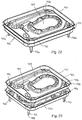
Figure 5 is a perspective view from the top of two of the support trays ofFigure 1 stacked in a first, nested configuration; -
Figure 6 is a plan view from above of the support tray ofFigure 1 ; -
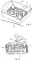
Figure 7 is a perspective view from the top of two of the support trays ofFigure 1 , with an endoscope and accessories placed in the trays, and the trays stacked in a second, spaced apart configuration; -
Figure 8 is a plan view from above of a support tray ofFigure 7 showing the position of an endoscope and accessories within the tray; -
Figure 9 is a perspective view of a storage assembly for an endoscope, including the support tray ofFigure 1 in position in the base of a bag, with an endoscope received in the tray; -
Figure 10 is a perspective view of the storage assembly ofFigure 9 , with the bag wrapped around the support tray and a closure device securing the bag closed; -
Figure 11 is an exploded view of a further embodiment of a support tray for supporting an endoscope; -
Figure 12 is an exploded view of a kit for the transportation of an endoscope according to the present invention, the kit comprising a support tray and a liner; -
Figure 13 illustrates a kit for the transportation of an endoscope according to a further embodiment of the present invention, the kit comprising a support tray, a liner and a cover in the form of a bag; -
Figure 14 illustrates a kit for the transportation of an endoscope according to another embodiment of the present invention, the kit comprising a support tray, a liner and a cover; -
Figure 15 illustrates a kit for the transportation of an endoscope according to a further embodiment of the present invention, the kit comprising a support tray and a liner; -
Figure 16 illustrates a kit for the transportation of an endoscope according to another embodiment of the present invention, the kit comprising a support tray, a liner and a cover in the form of a cinch pad; -
Figure 17 illustrates a kit for the transportation of an endoscope according to a further embodiment of the present invention, the kit comprising a support tray, a liner and a cover, the liner and cover being integrally formed; -
Figure 18 illustrates an integral liner and cover of a kit according to a further embodiment of the present invention, the liner and cover being integrally formed as an elongate sleeve; -
Figure 19 is a perspective view from the top of a support tray for an endoscope according to an embodiment of the present invention; -
Figure 20 is an end view of the support tray ofFigure 19 ; -
Figure 21 is a plan view from above of the support tray ofFigure 19 ; -
Figure 22 is a perspective view from the top of two of the support trays ofFigure 19 stacked in a first, nested configuration; -
Figure 23 is a perspective view from the top of two of the support trays ofFigure 19 stacked in a second, spaced apart configuration; -
Figure 24 is a exploded view from the top of an assembly including the support tray ofFigure 19 , a liner and a cover, with the cover in an open position; and -
Figure 25 is an exploded view from the top of the assembly ofFigure 23 , showing distinguishing means provided on the cover. -
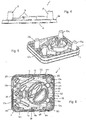
Figures 1 to 8 illustrate a first preferred embodiment of a support tray 1 for storing and transporting an endoscope. The support tray 1 comprises a substantiallyrigid base plate 2 and a plurality ofguide walls 4 extending from thebase plate 2. Theguide walls 4 are arranged to define areas of the support tray 1 on which anendoscope 6 and otherendoscopic accessories 8 may be placed in use, as shown most clearly inFigures 7 and 8 . - The
base plate 2 has a first side orupper surface 22 and an opposing second side orlower surface 24. In this example, thebase plate 2 is corrugated such that each of the first andsecond sides - The support tray 1 further comprises spacing means in the form of a plurality of support members or support posts 10. These support posts 10 extend from the first side of the
base plate 2 and are arranged such that two or more of the support trays 1 can be stacked in two different configurations, illustrated inFigures 5 and7 . In a first configuration the support trays 1 stack or nest such that there is minimal gap or distance between adjacent trays, as shown inFigure 5 . This enables the trays 1 to be transported and stored in a space saving manner when not in use. In a second configuration, shown inFigure 7 , the support trays 1 stack such that there is a gap or space between thebase plates 2 of adjacent trays. This enables, in use, anendoscope 6 andother accessories 8 to be retained on each of the trays 1 in the stack. - In this embodiment, the
base plate 2 of the support tray 1 is substantially rectangular and has opposing first and second side edges 12, 14 and opposing first and second end edges 16, 18.Corners 20 of thebase plate 2, between the side edges 12, 14 and end edges 16, 18, are rounded. A width of the support tray, i.e. the distance between side edges 12, 14 of thebase plate 2, is preferably between 40 cm and 45 cm. A length of the support tray, i.e. the distance between end edges 16, 18 of thebase plate 2, is preferably between 50 cm and 55 cm. These dimensions of the support tray 1 mean that the tray 1 is compatible with existing endoscope transport systems and storage facilities. - A
lip 26 extends around the perimeter of thebase plate 2 and projects upwards from thefirst side 22 of thebase plate 2. Thelip 26 extends continuously around thebase plate 2 so as to form a containing barrier for any liquid that may be present on theupper surface 22 of thebase plate 2. In this example thelip 26 has a cross-section in the shape of an inverted U or V, such that a correspondinggroove 27 is formed in thesecond side 24 of thebase plate 2 proximate the perimeter. - As shown most clearly in
Figures 1, 3 and4 , foursupport posts 10 extend from thefirst side 22 of thebase plate 2 in a direction substantially perpendicular to a plane of thebase plate 2. Each of the support posts 10 terminates in a distal orupper end 28. - In this embodiment the support posts 10 are tapered and are in the form of truncated cones. The support posts 10 are hollow and an
opening 30 of eachsupport post 10 is provided in thesecond side 24 of thebase plate 2 providing access to an interior volume of thesupport post 10. A first pair of thesupport posts 10a is located proximate thefirst end edge 16 of thebase plate 2 and a second pair of the support posts 10b is located proximate thesecond end edge 18. A distance between the first pair ofsupport posts 10a is greater than a distance between the second pair of support posts 10b, in a direction substantially parallel to the end edges 16, 18. - In this way, when two support trays 1 are stacked in the first orientation with respect to each other, a
distal end portion 32 of eachsupport post 10 of one of the trays 1 is received through theopening 30 into the interior volume of thecorresponding support post 10 of the second one of the trays 1. In particular, anend portion 32 of each of the first pair ofsupport posts 10a of one of the trays 1 is received within the interior volume of each of the corresponding first pair ofsupport posts 10a of the second one of the trays 1 and anend portion 32 of each of the second pair of support posts 10b is received within the interior volume of each of the corresponding second pair of support posts 10b. In this configuration, therefore, the two support trays 1 are nested together. - In order to stack the two support trays 1 in the second orientation with respect to each other, one tray 1 is rotated 180° with respect to the other tray 1 about an axis perpendicular to the
base plate 2. In this orientation, the positioning of the pairs of support posts 10 means that the support posts 10 of one tray are no longer aligned with theopenings 30 of the other tray 1 and, accordingly, thedistal end 28 of each of the support posts 10 of one of the trays 1 contacts a part of thesecond side 24 of thebase plate 2 of the other one of the trays 1. As such, the trays 1 are supported with theirbase plates 2 in a spaced apart relationship permitting anendoscope 6 and othermedical accessories 8 to be retained on theupper surface 22 of each support tray 1, as shown inFigure 7 . - Although in this embodiment the support trays 1 are rotated 180° with respect to each other between the first and second orientations, it will be appreciated that in other embodiments the trays 1 may be rotated with respect to each other through a different angle. For example, the trays 1 may be rotated through 90° with respect to each other.
- In order to prevent the
lower surface 24 of a tray 1 contacting the medical equipment retained on a tray 1 below, a height of each of the support posts 10 is such that when, in use, anendoscope 6 is laid on thefirst side 22 of thebase plate 2, no part of theendoscope 6 projects above the height of the support posts 10. Typically, the height of all of the support posts 10 will be the same. - The height of the support posts 10 is preferably substantially greater than the height of the
lip 26. Typically the height of the support posts 10 will be greater than twice the height of thelip 26, and more preferably greater than four times the height of thelip 26. The support posts 10, therefore, provide a means for stacking the trays 1 in a spaced apart relationship and also determine the distance betweenadjacent base plates 2 in this stacked configuration. - The
guide walls 4 project from thefirst side 22 of thebase plate 2. Theguide walls 4 are positioned such that parts of theendoscope 6 andaccessories 8 can be placed around and between theguide walls 4 to retain them in a substantially fixed configuration with respect to the tray 1. A height of theguide walls 4 is preferably less than a height of the support posts 10.Different guide walls 4 may be of different heights. Theguide walls 4 may be of different lengths and shapes. For example, some of theguide walls 4 may be straight, whileother guide walls 4 may be curved. Theguide walls 4 are preferably of a hollow construction, each having anopening 25 in thesecond side 24 of thebase plate 2. This allows correspondingguide walls 4 to fit into each other when the trays 1 are stacked in the first orientation, i.e. when the trays 1 are nested together. - In this example, a series of discrete guide walls 4a are located spaced apart, around the
base plate 2 at a constant distance from thelip 26. These guide walls 4a, therefore, define aperimeter region 33 of the support tray 1 which may receive, in use, acontrol wire 34 ofbiopsy forceps 36, for example, as shown most clearly inFigure 8 . - A protective guide wall 4b is located adjacent to but spaced from a part of the
lip 26 along theside edge 14. Thegap 38 between the guide wall 4b and thelip 26 provides a region for receiving atip 40 of theendoscope 6, as shown most clearly inFigure 8 . Thetip 40 can, therefore, be retained in a fixed position within the tray 1 and is protected between the guide wall 4b and thelip 26. In some embodiments the protective guide wall 4b is located adjacent theother side edge 12, or adjacent one of the end edges 16, 18. The tray may include more than one protective guide wall in order to accommodate different lengths ofendoscope 6. Furthermore, it will be appreciated that in other embodiments the tray may comprise a pair of protective guide walls between which theendoscope tip 40 is received. The protective guide wall(s) 4b and thelip 26 preferably have a height greater than the diameter of thetip 40 of theendoscope 6. -
Further guide walls 4 are located so as to retain the other parts of theendoscope 6 in a desired position with respect to the support tray 1. In particular,guide walls 4 may define regions of thebase plate 2 for receiving thecontrol body 42,insertion tube 44 andlight guide connector 46. Regions of theupper surface 22 of thebase plate 2 may include symbols or other indicia to indicate to a user where to place each part of theendoscope 6 in use. The indicia may comprise a shallow recess in thefirst side 22 of thebase plate 2 to facilitate the correct positioning of theendoscope 6. - The
guide walls 4 are, preferably, located such that when anendoscope 6 is correctly positioned on the tray 1 around and between theguide walls 4, the possibility of damage to theendoscope 6 is minimised. Distances betweenadjacent guide walls 4 and betweenguide walls 4 andposts 10 or thelip 26 are preferably such that possible movement of theendoscope 6 on the support tray 1 is minimised. Furthermore, the arrangement of theguide walls 4 is such that theendoscope 6 is not coiled too tightly when placed in the tray 1. - In this embodiment the support tray 1 also includes a
receptacle 48 for containing a liquid. Thereceptacle 48 comprises acontinuous side wall 50 projecting from thefirst side 22 of thebase plate 2 and fully surrounding abase 52 of thereceptacle 48. Thereceptacle 48 is sized to hold about 500 ml of liquid. In some embodiments markings may be included on a part of theside wall 50 to indicate volume levels, such as 250 ml and 500 ml. In other embodiments all or part of theside wall 50 may include a step. The step is preferably positioned such that filling the receptacle with liquid up to the level of the step fills the receptacle with a known volume of liquid, for example 250 ml. - The
receptacle 48 may, in use, be filled with a detergent solution that is used to perform an initial cleaning step on theendoscope 6. In these embodiments theendoscope 6 is cleaned with the detergent solution and then placed into the tray 1 as described above. Any liquid that drains from the surface of theendoscope 6 collects in the furrows of theupper surface 22 of thebase plate 2 and is retained in the tray 1 by thelip 26. Because theendoscope 6 will tend to contact the ridges of thecorrugated base plate 2 theendoscope 6 will, typically, be supported above any liquid in the furrows. - As shown most clearly in
Figures 7 and 8 , in this embodiment, guidewalls 4 positioned to retain thelight guide connector 46 and a part of theside wall 50 of thereceptacle 48 form a generally circular or elliptical wall around which theinsertion tube 44 of theendoscope 6 is placed. - The support tray 1 is preferably designed to be single use, i.e. to be used once to hold a clean endoscope ready for use and once to hold the same endoscope once it has been used, so that the endoscope can be transported from and to cleaning and disinfecting facilities. Once the tray 1 has been used to hold a used, dirty endoscope, the tray 1 is not subsequently re-used to hold a clean endoscope or any other dirty endoscope, and is disposed of in a suitable manner. In some embodiments it may be desirable, however, if the tray can be reused a number of times, for example to hold endoscopic equipment throughout a day.
- The tray 1 is preferably made from a suitable material such as waxed paperboard, bagasse or corn starch. The material from which the tray 1 is made is preferably non-absorbent and is preferably biodegradable. In this example the tray 1 is of unitary, one-piece construction and will typically be made by moulding or pressing sheet material into the required 3-dimensional shape. In embodiments in which the support tray 1 is to be reused, the tray 1 is advantageously made from a material that can be sterilised.
- As illustrated in
Figures 9 and 10 , the support tray 1 is designed to be used in conjunction with astorage bag 54 for enclosing and transporting theendoscope 6 andaccessories 8, although it will be appreciated that the support tray 1 may also be used independently. - In embodiments in which a storage bag is used, the
storage bag 54 is preferably made from a flexible plastics material and has sufficient barrier properties so as to be able to retain moisture within thebag 54 when the bag is closed. The plastics material is preferably food-grade plastic. Additionally, thebag 54 is resistant to cleaning and sterilisation fluids to which it may be exposed during the cleaning and processing of the medical equipment. In this example, the plastics material is transparent so that the contents of thebag 54 can be seen at all times; however, in other embodiments thebag 54 may be printed with graphics or text, which may include warning symbols and/or instructions for use. Thebag 54 preferably has a rectangular or square base, facilitating placement of the support tray 1 within thebag 54. - Two
closure devices 56, only one of which is shown inFigures 9 and 10 , are provided to seal thebag 54 closed. Theclosure devices 56 are each single use, and permit the identification of the medical equipment held within thebag 54. - The
closure devices 56 may be cable ties having a head portion and a tail portion. The tail portion preferably includes engagement means which, in use, engage with corresponding engagement means in the head portion. The engagement means are arranged such that the tail portion can be engaged with the head portion so as to form a closed loop in the cable tie, but the tail portion cannot be disengaged from the head portion without permanently disabling or breaking the cable tie. In this way, the engagement means forms a one-way locking means and the closure devices are single use. - The closure devices may include a 'break to open' feature. For example, each cable tie may include a tab portion that is located between the head portion and the tail portion of the cable tie. The tab portion includes a grip portion suitable for gripping between a thumb and finger of a user. The tab portion further includes a line of weakness in the form of a thinner section of plastics material that spans the width of the cable tie. The tab portion is designed such that, as a user pulls the grip portion, the cable tie tears along the line of weakness thereby breaking the cable tie such that the cable tie cannot be used again. In some embodiments the line of weakness may be provided by a line of perforations.
- Each of the closure devices includes distinguishing means to enable the closure devices to be distinguished from each other. In some embodiments the distinguishing means are in the form of colours, for example one of the closure devices may be red and the other closure device may be green. In other embodiments, the distinguishing means may additionally or alternatively include symbols, lettering or numbers to enable the two closure devices to be distinguished. For example, the head portion of one of the cable ties may include the word CLEAN and the head portion of the other cable tie may include the word DIRTY.
- Furthermore, each of the closure devices includes associated or interrelated identification means (not shown). This identification means allows identification and traceability of the medical equipment held within the
bag 54. The identification means may comprise a unique serial number, a barcode or other suitable means to identify the specific piece of medical equipment. The identification means on each of the two closure devices may be identical, or the identification means may be interrelated, for example including consecutive or related serial numbers (e.g. 123456A and 123456B). The use of interrelated identification means permits the piece of medical equipment to be identified and the state of the equipment to be determined, e.g. clean or dirty. - The ability to uniquely identify the endoscope or other medical equipment held within the
bag 54 and to determine the state of the equipment is particularly important, as it is a requirement to record each step of the cleaning and decontamination cycle of the endoscope. - The use of a kit comprising the support tray 1, the
bag 54 and theclosure devices 56 will now be described in relation to the storage and transportation of anendoscope 6. - The kit is designed to initially be used to store a cleaned
endoscope 6 ready for use. Thestorage bag 54 is opened such that theendoscope 6 may be placed inside without coming into contact with the outside surface of thebag 54. In this way, the sides of thebag 54 may be folded or rolled down, as shown inFigure 9 . The support tray 1 is then laid within thebag 54 with thefirst side 22 and the support posts 10 uppermost. Theendoscope 6 is then laid in the tray 1. Alternatively theendoscope 6 may be placed in the tray 1 before the tray 1 is placed within thebag 54. - A first one of the two
closure devices 56 is placed within thebag 54 together with theclean endoscope 6. Theclosure device 56 placed inside thebag 54 is the one used to indicate that theendoscope 6 is used and dirty. - The sides of the
bag 54 are then brought together and thebag 54 is sealed closed with thesecond closure device 56. Thisclosure device 56 indicates that theendoscope 6 within thebag 54 is clean. - The
endoscope 6 may then be transported fully protected by the support tray 1 and enclosed within thebag 54 to wherever it is needed. The dimensions of the support tray 1 are, preferably, such that the tray 1 fits directly into a suitable, existing wheeled cart or other transportation system without the requirement for a traditional tray or shallow container to be used. - In order to remove the
endoscope 6 from thebag 54, a user must break theclosure device 56 around thebag 54. Because the break in theclosure device 56 is permanent, theclosure device 56 cannot be reused and must be disposed of. This reduces the likelihood of cross-contamination of theendoscope 6 through opening and re-closing of thebag 54 prior to use. - After it has been used, the
endoscope 6 is placed back onto the support tray 1 inside thebag 54. As described above, a detergent solution held within areceptacle 48 of the tray 1 may be used to carry out a first stage clean of theendoscope 6. Thefirst closure device 56 is then sealed around thebag 54, as illustrated inFigure 10 . Thisclosure device 56 indicates that theendoscope 6 is used and dirty. Theendoscope 6, protected by the tray 1 and enclosed within thebag 54, may then be transported to suitable cleaning facilities. - As before, the
closure device 56 must be broken to remove it from thebag 54 to enable the subsequent cleaning and disinfection of theendoscope 6. Once theendoscope 6 has been cleaned, a new kit is used to store theendoscope 6 ready for use. - Although in the preceding embodiments the
closure devices 56 have comprised cable ties, the closure devices may be of any suitable type and may include, for example, a cable lock, single use padlock or an elasticated band. - In some embodiments it may be desirable if the kit includes a third closure device (not shown). This third closure device also includes distinguishing means, to enable the closure device to be distinguished from the first and second closure devices, and identification means at least similar to those of the first and second closure devices. In particular, the identification means of the third closure device may be related to or identical to the identification means of the first and second closure devices. The set of three closure devices may be used to distinguish whether the endoscope within the bag is used and dirty, clean and wet, or clean and dry. The three closure devices may be coloured red, blue and green for example.
- Providing interrelated identification means on each of the closure devices means that the medical equipment, in this case the endoscope, may be traced easily throughout its use, allowing the required records to be efficiently maintained within a hospital or other healthcare facility. It will be appreciated that in some cases it is not necessary to provide interrelated or identical identification means on each of the closure devices because, for example, the actual identification means (e.g. serial number) can simply be recorded at each stage in the process in relation to that specific piece of medical equipment.
- As described above, two or more support trays 1
holding endoscopes 6 may be stacked one on top of the other with the trays 1 in the second orientation. As such it is possible to place a single support tray 1 in abag 54 and then stack this assembly on top of another support tray 1 sealed within abag 54. This allows a plurality ofendoscopes 6 to be transported in a stack whilst eachendoscope 6 is sealed within itsown bag 54 and labelled with itsunique closure device 56. It will be appreciated that it is also possible to stack two or more trays 1 together within asingle bag 54 if this is desired. - In this embodiment the support posts 10 have been illustrated as separate members positioned inwardly of the
lip 26 of the tray 1. In other embodiments, however, the support posts 10 may form part of the lip. It will also be appreciated that, in other embodiments, the support posts 10 may extend from the second side of thebase plate 2. In these embodiments each of the support posts 10 preferably has a height, or length, between thebase plate 2 and thedistal end 28 of thepost 10 that is greater than the height of theguide walls 4. - In some embodiments it may also be desirable if the support tray 1 included a tab portion (not shown) that extends outwardly from a part of the perimeter of the
base plate 2. The tab portion preferably extends horizontally in a plane substantially parallel to the plane of thebase plate 2. An upper surface of the tab portion provides a flat surface on which, in use, a user may write or apply an adhesive label to aid in the identification of the endoscope in the tray 1. The tab portion preferably extends from one of the twoend edges -
Figure 11 shows a second preferred embodiment of thesupport tray 101 according to the present invention. Many of the features of thissupport tray 101 are the same as or similar to features of the support tray 1 of the first embodiment, and like features are indicated by reference numerals incremented by 100. - In this embodiment the
tray 101 comprises abase plate component 158 includingbase plate 102, support posts 110 and guidewalls 104. These features are substantially identical to those of the first embodiment and will, therefore, not be described further here. As in the first embodiment, although the support posts 110 have been illustrated as extending from thefirst side 122 of thebase plate 102, in some embodiments the support posts 110 extend from the second side of thebase plate 102. - The
base plate component 158 further includes anannular locating rail 160 that projects from thefirst side 122 of thebase plate 102. The height of therail 160 is similar to the height of thelip 126 of thetray 101, and is substantially less than the height of the support posts 110. - In this embodiment a
first part 159 of thefirst side 122 of thebase plate 102 external to and surrounding theannular rail 160 is corrugated and asecond part 161 of thefirst side 122 within and surrounded by theannular rail 160 is substantially flat. - The
support tray 101 further comprises aseparate receptacle element 162 that is configured to be received on thebase plate 102. In particular, theelement 162 comprises a generallycircular base 163 including, on its underside, a groove or similar recess (not shown) that is sized to engage with the locatingrail 160 on thebase plate 102. - The
receptacle element 162 includes areceptacle 148 for receiving, in use, a liquid such as a detergent solution. Thisreceptacle 148 has been described above in relation to the first embodiment of the tray 1 and will not be described further here. Theelement 162 further includesguide walls 104 configured to receive therebetween a part of theendoscope 6. In this embodiment theguide walls 104 are positioned to receive thelight guide connector 46 of theendoscope 6. - The
receptacle element 162 is designed to locate over the locatingrail 160 with at least a part of thebase 163 of thereceptacle element 162 in contact with thefirst side 122 of thebase plate 102. - The
element 162 is not, however, secured to thebase plate 102. The complementary circular shape of thebase 163 of theelement 162 and theannular rail 160 allows theelement 162 to be placed over therail 160 in any orientation with respect to thebase plate 102. Furthermore, once thereceptacle element 162 has been engaged with the locatingrail 160, theelement 162 can be rotated with respect to thebase plate 102 about an axis of rotation that is perpendicular to the plane of thebase plate 102. - The umbilical tube or light guide tube of an endoscope can be different lengths depending on the type or make of the endoscope. The
receptacle element 162 is positioned on thebase plate 102 so that the light guide tube wraps around thereceptacle 148 and theguide walls 104. Because the light guide tube can be different lengths, the final position of thelight guide connector 46 can therefore be at different orientations relative to thebase plate 102. In this embodiment thereceptacle element 162 can be rotated such that theguide walls 104 are correctly positioned to receive the light guide connector therebetween. - Furthermore, in some embodiments it may be advantageous if the
receptacle element 162 is designed to be a disposable part of thesupport tray 101, while the base plate component 58 is designed to be repeatedly cleaned and sterilised. In these embodiments thereceptacle element 162 may be single use and may be made of a material such as bagasse or corn starch, while thebase plate component 158 is multi-use and is made of a suitable plastics material. - The locating
rail 160 and thereceptacle element 162 may include complementary engaging means such that thereceptacle element 162 positively engages with the locatingrail 160, or clicks into position. Once engaged, the engaging means still permits the rotation of thereceptacle element 162 with respect to thesupport tray 101 about an axis that is substantially perpendicular to thebase plate 102 of thesupport tray 101. In some embodiments the engaging means may be configured such that a part of thereceptacle element 162 must be broken to remove thereceptacle element 162 from thesupport tray 101. This ensures that thereceptacle element 162 is single use. - The
base plate component 158 and thereceptacle element 162 of thesupport tray 101 are each designed to be able to be nested so that they can be stored before use. -
Figures 12 to 17 illustrate several embodiments of a kit for storing and transporting an endoscope according to the present invention. Each of these kits comprises asupport tray 101 including abase plate 102, areceptacle 162, and barrier means including a liner part or portion. In these embodiments thesupport tray 101 is typically not single use and at least a part of the liner portion is configured to locate between the endoscope and thesupport tray 101 to prevent or minimise contamination from the endoscope contacting thesupport tray 101. - In a first embodiment of a
kit 200, shown inFigure 12 , the barrier means 264 comprises aflexible sheet 266 of plastics material. Thesheet 266 includes a substantially rectangular liner part orportion 267 the dimensions of which are greater than the dimensions of abase plate 102 of thesupport tray 101. In this way, theliner portion 267 can drape over and conform to thebase plate 102 of thetray 101, the support posts 110 and theguide walls 104, while still covering all of thefirst side 122 of thesupport tray 101. - In this example the
base plate 102 includes anannular locating rail 160, and theliner portion 267 includes a spot orcircle 268 that indicates the correct positioning of thesheet 266 with respect to theunderlying support tray 101. In use, a user places theflexible sheet 266 such that thespot 268 overlies the region of thesupport tray 101 defined by the locatingrail 160. This ensures that thesheet 266 covers all of thesupport tray 101. - The
receptacle 162 is substantially circular and comprises abase 163 and aside wall 170 that extends around the perimeter of thereceptacle 162. A dividingwall 171 divides thereceptacle 162 into twocompartments first compartment 172 is designed to hold a volume of a liquid such as a detergent solution and asecond compartment 173 is configured to receive the light guide connector of an endoscope. - In use, once the
liner portion 267 has been laid over thesupport tray 101, thereceptacle 162 is placed onto thebase plate 102 of thesupport tray 101 in engagement with the locatingrail 160. In this way, a part of theliner portion 267 is located between thereceptacle 162 and thesupport tray 101 to hold theliner portion 267 in position with respect to thesupport tray 101. Thereceptacle 162 and locatingrail 160, therefore, function as retaining means for retaining theliner portion 267 in contact with thebase plate 102. - The
sheet 266 also includes two cover parts orportions cover portions 274 extends from afirst side edge 276 of theliner portion 267 and a second one of thecover portions 275 extends from an opposing,second side edge 277 of theliner portion 267. In this way theliner portion 267 and coverportions liner portion 267 is located between the twocover portions - The
first cover portion 274 includes a first distinguishing means and thesecond cover portion 275 includes a second distinguishing means, the first and second distinguishing means being different. In this example, thefirst cover portion 274 is coloured red and thesecond cover portion 275 is coloured green. - In use, a user first places the
liner portion 267 and thereceptacle 162 on thesupport tray 101 as described above. A clean endoscope (not shown) is then laid on thesupport tray 101 on top of theliner portion 267. The weight of the endoscope assists in conforming theliner portion 267 to theunderlying support tray 101. The user then folds thefirst cover portion 274 over the top of the endoscope, followed by thesecond cover portion 275, such that thegreen cover portion 275 is uppermost and visible. This indicates that the endoscope is clean and ready to use. Thesecond cover portion 275 may be secured to thefirst cover portion 274 in this covered position by means of anadhesive strip 276 or similar along an edge of one or both coverportions - After the endoscope has been used, the
first compartment 172 of thereceptacle 162 can be filled with a detergent solution to allow an initial cleaning of the endoscope to be carried out. The endoscope is then laid back onto theliner portion 267 on thesupport tray 101. - In some embodiments the
second cover portion 275 is folded over the top of the endoscope, followed by thefirst cover portion 274, such that thered cover portion 274 is uppermost and visible. This indicates that the endoscope is used and dirty. - In other embodiments, the
second cover portion 275 is separated from the rest of thesheet 266 and only thefirst cover portion 274 is folded over the endoscope. In these embodiments a line of perforations may be located along theboundary 277 between theliner portion 267 and thesecond cover portion 275. - Again, the
first cover portion 274 may be secured in the covered position by, for example, anadhesive strip 276. - In a second embodiment of a
kit 300, shown inFigure 13 , the barrier means 364 comprises aliner part 367 in the form of a flexible sheet of plastics material and acover part 378 in the form of abag 379. Theliner part 367 is, therefore, separate from thecover part 378 in this embodiment. - The
liner part 367 is substantially rectangular and the dimensions of theliner sheet 367 are greater than the dimensions of abase plate 102 of thesupport tray 101. In this way, theliner sheet 367 can drape over and conform to thebase plate 102 of thetray 101, the support posts 110 and theguide walls 104, while still covering all of thefirst side 122 of thesupport tray 101. - The
bag 379 is permanently sealed at one end and is sized to receive thesupport tray 101,liner part 367, endoscope andreceptacle 162. Thebag 379 is made from a flexible material and will typically be made from a flexible plastics material. Once thesupport tray 101 and other items have been placed within thebag 379, asecond end 380 of thebag 379 may be sealed with any suitable means such as a clip or cable tie, or by means of an adhesive strip or similar. - In this embodiment a first surface of the
bag 379 includes a first distinguishing means and a second surface of thebag 379 includes a second distinguishing means, the first and second distinguishing means being different. In this example, the first surface is coloured red and the second surface is coloured green. As such, thebag 379 may initially be configured such that the green surface is outermost and the red surface is on the interior of thebag 379. Thebag 379 may then be turned inside-out, so that the red surface is outermost and the green surface becomes the interior surface of thebag 379. - In use, the
liner part 367 is laid over thesupport tray 101 and thereceptacle 162 is placed onto thebase plate 102 of thesupport tray 101 such that a part of theliner sheet 367 is located between thereceptacle 162 and thesupport tray 101, thereby holding theliner part 367 in position with respect to thesupport tray 101. An endoscope (not shown) is then placed on theliner sheet 367 on thesupport tray 101. The user then configures thebag 379 such that either the red or green surface is outermost and visible, depending on the state of the endoscope, and places thesupport tray 101 into thebag 379. Thebag 379 may then be sealed using any appropriate sealing means. - In other embodiments separate green and red bags may be provided. Alternatively, a single bag may be provided and two clips, ties or other sealing means may be provided; each of the sealing means having a different distinguishing means. For example, red and green clips or cable ties may be provided.
- A third embodiment of a
kit 400 is shown inFigure 14 . In this embodiment the barrier means 464 comprises aliner part 467 and aseparate cover part 478. Theliner part 467 comprises aflexible sheet 467 of plastics material that is sized to cover thesupport tray 101 as described above in relation to the second embodiment. - The
cover 478 is in the form of substantiallyrigid shell 482. By substantially rigid it is meant that theshell 482 is able to support its own weight and, therefore, retains its shape. Theshell 482 comprises atop plate 483 andside walls 484 that extend continuously around the perimeter of thetop plate 483. Afree edge 485 of theside walls 484, furthest from thetop plate 483, has a shape and dimensions substantially the same as those of thebase plate 102 of thesupport tray 101. Thecover 478, therefore, fits over thesupport tray 101 with thefree edge 485 engaging with a perimeter edge of thebase plate 102. - A height of the
side walls 484 of theshell 482 is such that thetop plate 483 extends over theguide walls 104 of thesupport tray 101 and any endoscope that is lying on thetray 101. The height of theside walls 484 is, however, less than the height of the support posts 110. - In this embodiment the
support tray 101 includes four support posts 110. Thecover shell 482 includes fourcap portions 486 that are formed in thetop plate 483. Thecap portions 486 extend from thetop plate 483 in a direction substantially opposite to theside walls 484. The shape and dimensions of thecap portions 486, together with their positions relative to the rest of theshell 482, are such that, when thecover 478 is placed over thesupport tray 101, an upper portion of eachsupport post 110 is received within arespective cap portion 486. - In use, after the
liner part 467,receptacle 162 and endoscope (not shown) have been placed onto thesupport tray 101, thecover 478 is placed over thetray 101 so that the support posts 110 engage in thecap portions 486. Providingcap portions 486 that are proud of thetop plate 483 of theshell 482 has two key advantages. Firstly, thecap portions 486 allow thecover 478 to be engaged securely and in the correct position with respect to thesupport tray 101. Secondly, thecap portions 486 permit thesupport tray 101 to be stacked as described previously, with the support posts 110 engaging with a part of the second, underside of thebase plate 102 of anothertray 101 to hold the trays in a spaced apart configuration. - The
cover 478 will typically be formed by vacuum forming and will be made from a suitable plastics material. - In each of the second and third embodiments of a
kit separate liner part support tray 101 with the edge of the sheet being drawn around and under the perimeter edge of thebase plate 102. The elasticated edge, therefore, functions as retaining means for retaining theliner part base plate 102. - A fourth embodiment of a
kit 500 is illustrated inFigure 15 . In this embodiment the barrier means 564 comprises a substantiallyrigid liner part 567. Theliner part 567 will typically be made of a suitable plastics material and will be vacuum formed into the required shape. The shape of theliner part 567 is such that it substantially conforms to the shape of thefirst side 122 of thebase plate 102 of thetray 101, theguide walls 104 and the support posts 110. Theliner part 567 can, therefore, be placed over thesupport tray 101 to fully cover all of the features of theupper surface 122 of thesupport tray 101. - In some embodiments the
liner part 567 also includes one or more locating features positioned to aid in the correct placement of thereceptacle 162 on theliner part 567 andsupport tray 101. - A fifth embodiment of a
kit 600 is shown inFigure 16 . In this embodiment the barrier means 664 comprises aliner part 667 in the form of a first flexible sheet and acover part 678 in the form of a second flexible sheet 688. The first flexible sheet is the same as theflexible sheet 367 of the second embodiment and, as such, will not be described further here. - The second flexible sheet 688 comprises a liquid-
proof base sheet 689 having a substantially rectangular central portion and two triangular or trapezoidal wing portions extending from either side of the central portion. Anabsorbent pad 690 is attached to a first or upper side of the central portion of thebase sheet 689 and adrawstring 691 extends around the perimeter of thebase sheet 689. In some embodiments the second flexible sheet may be a CinchPad (RTM). - In use, the second flexible sheet 688 is placed on a surface with the
absorbent pad 690 uppermost. Thesupport tray 101 is then placed centrally on the sheet 688 and theliner sheet 667 draped over thetray 101. Theliner sheet 667 will typically be sized such that the edges of theliner sheet 667 lie in contact with theabsorbent pad 690 around thesupport tray 101. Thereceptacle 162 and the endoscope (not shown) are placed on top of theliner sheet 667 on thesupport tray 101 as previously described. - To cover and transport the endoscope, the
drawstrings 691 are pulled so as to gather the edges of thebase sheet 689 together, thereby drawing the second flexible sheet 688 over and around thesupport tray 101 and endoscope. -
Figure 17 illustrates a sixth embodiment of akit 700 in which the barrier means 764 comprises aliner part 767 and acover part 778. In this embodiment theliner part 767 and coverpart 778 are integrally formed and are made of a flexible sheet material. Theliner part 767 extends over and conforms to the shape of the upper side of thesupport tray 101. Thecover part 778 surrounds theliner part 767 and a free, perimeter edge of thecover part 778 includes adrawstring 791 so that thecover part 778 can be drawn up and around thesupport tray 101, as illustrated inFigure 17 . A receptacle has not been shown inFigure 17 for clarity. - In order to secure the barrier means 764 to the
support tray 101, securing means 792 in the form of a strap or panel is provided on the underside of the flexible sheet. The securing means 792 is fixed to the flexible sheet in such a way as to enable thesupport tray 101 to be located between theliner portion 767 and the securing means 792. - In some embodiments the flexible sheet may include a base sheet and an absorbent pad as described above in relation to the previous embodiment. In these embodiments the absorbent pad may be attached to the base sheet so as to form a pocket for receiving the support tray between the base sheet and the absorbent pad. In this way, the absorbent pad is the liner part and the base sheet is the cover part of the barrier means.
- A further embodiment of barrier means 864 that may be used together with a
support tray 101 andreceptacle 162 as part of akit 800 according to the invention is illustrated inFigure 18 . In this embodiment aliner part 867 and acover part 878 are integrally formed as a flexible, elongate sleeve orsheath 893. Thesleeve 893 is closed at afirst end 894 and is dimensioned to surround anendoscope 6 and to extend fully along the length of theendoscope 6 to cover theinsertion tube 44, thecontrol body 42 and thelight guide connector 46. - In use, the
sleeve 893 is extended over theendoscope 6 and theendoscope 6 is then placed onto asupport tray 101. Accordingly aliner part 867 of thesleeve 893 will lie underneath theendoscope 6 between theendoscope 6 and thesupport tray 101, and acover part 878 of thesleeve 893 will extend over the top of theendoscope 6. - The
sleeve 893 will typically be made of a suitable plastics material. In some embodiments a first surface of thesleeve 893 is coloured red and a second surface of thesleeve 893 is coloured green. As such, thesleeve 893 may initially be configured such that the green surface is outermost and the red surface is on the interior of thesleeve 893. Thesleeve 893 may then be turned inside-out, so that the red surface is outermost and the green surface becomes the interior surface of thesleeve 893. - A
second end 895 of thesleeve 893 may be secured closed using any suitable closure means. In one embodiment the closure means comprises aclip 896 having two arm portions hingedly connected at a first end. The second end of each of the arm portions may be latched together so as to clamp thesleeve 893 between the arm portions. In other embodiments the closure means may include ties or bands. The closure means may be single use. - In some embodiments the closure means includes means for indicating a date and/or a time. This may be used, for example, to display a date or time at which the
endoscope 6 was cleaned or placed inside the sleeve. - In some embodiments the
second end 895 of thesleeve 893 includes a ring member (not shown). The ring member retains a generally circular shape while thesleeve 893 is being extended along the length of theendoscope 6. The ring member, therefore, aids in inserting theendoscope 6 into thesleeve 893. Once theendoscope 6 has been covered by thesleeve 893, the ring member may be twisted by a user so as to close thesecond end 895 of thesleeve 893. The ring member may, for example, be made from a length of metal wire. - In some embodiments the ring member may include a handle portion that extends radially outwards. In use a user may grip this handle portion to help draw the
sleeve 893 over and along theendoscope 6. - In some embodiments it may be desirable to trap the
second end 895 of thesleeve 893 under thereceptacle 162 when thereceptacle 162 is placed on thesupport tray 101. In particular, thereceptacle 162 may click or latch into engagement with a locatingrail 160 on thesupport tray 101 and theend 895 of the sleeve 89 may be located between thereceptacle 162 and thesupport tray 101.
The inclusion of barrier means having a liner portion that is disposed between the endoscope and support tray in use minimises contamination of the support tray and allows the support tray to be designed to be reusable, The receptacle, however, that is seated on top of the liner portion will typically be single-use and disposable. The use of barrier means does not, however, preclude the use of a single-use or disposable support tray. - Although in the embodiments shown in
Figures 12 to 18 the support posts were illustrated as extending from the first side of the base plate, in other embodiments the support posts may extend from the second side of the base plate, i.e. from an opposite side of the base plate to the guide walls. -
Figures 19 to 23 illustrate a third preferred embodiment of asupport tray 901 for storing and transporting an endoscope. Thesupport tray 901 comprises a substantiallyrigid base plate 902 and guidewalls 904 extending from thebase plate 902. Theguide walls 904 are arranged to define areas of thesupport tray 901 on which anendoscope 6 and other endoscopic accessories may be placed in use. - The
base plate 902 has a first side orupper surface 922 and an opposing second side orlower surface 924. - The
support tray 901 further comprises a plurality of support legs or support posts 910. Thesesupport legs 910 extend from thesecond side 924 of thebase plate 2 and are arranged such that two or more of thesupport trays 901 can be stacked in two different configurations, illustrated inFigures 22 and 23 , in a similar manner to thesupport trays 1, 101 of the first and second embodiments. - In this embodiment, the
base plate 902 of thesupport tray 901 is substantially rectangular and has opposing first and second side edges 912, 914 and opposing first and second end edges 916, 918.Corners 920 of thebase plate 902, between the side edges 912, 914 and endedges base plate 902, is preferably between 40 cm and 45 cm. A length of the support tray, i.e. the distance between end edges 916, 918 of thebase plate 902, is preferably between 50 cm and 55 cm. These dimensions of thesupport tray 901 mean that thetray 901 is compatible with existing endoscope transport systems and storage facilities. - A perimeter wall or
lip 926 extends around the perimeter of thebase plate 902 and projects upwards from thefirst side 922 of thebase plate 902. Thelip 926 extends continuously around thebase plate 902 so as to form a containing barrier for any liquid that may be present on theupper surface 922 of thebase plate 902. - As shown most clearly in
Figure 20 , the foursupport legs 910 extend from thesecond side 924 of thebase plate 902 in a direction substantially perpendicular to a plane of thebase plate 902. Each of thesupport legs 910 terminates in a distal end orfoot 928. - In this embodiment the
support legs 910 are tapered and are in the form of truncated cones. Thesupport legs 910 are hollow and anopening 930 of eachsupport leg 910 is provided in thefirst side 922 of thebase plate 902 providing access to an interior volume of thesupport leg 910. A first pair of thesupport legs 910a is located proximate thefirst end edge 916 of thebase plate 902 and a second pair of the support legs 910b is located proximate thesecond end edge 918. A distance between the first pair ofsupport legs 910a is greater than a distance between the second pair of support legs 910b, in a direction substantially parallel to the end edges 916, 918. - In this way, when two
support trays 901 are stacked in the first orientation with respect to each other, adistal end portion 932 of eachsupport leg 910 of one of thetrays 901 is received through theopening 930 into the interior volume of thecorresponding support leg 910 of the second one of thetrays 901, as described above in relation to the support posts 10 of the first embodiment of the support tray 1. In this configuration, therefore, the twosupport trays 901 are nested together, as shown inFigure 22 . - In order to stack the two
support trays 901 in the second orientation with respect to each other, onetray 901 is rotated 180° with respect to theother tray 901 about an axis perpendicular to thebase plate 902. In this orientation, the positioning of the pairs ofsupport legs 910 means that thesupport legs 910 of one tray are no longer aligned with theopenings 930 of theother tray 901 and, accordingly, thefoot 928 of each of thesupport legs 910 of one of thetrays 901 contacts a part of thefirst side 922 of thebase plate 902 of the other one of thetrays 901. As such, thetrays 901 are supported with theirbase plates 902 in a spaced apart relationship permitting anendoscope 6 and other medical accessories to be retained on theupper surface 922 of eachsupport tray 901. In preferred embodiments recesses 934 are provided in theupper surface 922 of thetray 901 or in theguide walls 904 for receiving thefoot 928 of eachsupport leg 910. - Although in this embodiment the
support trays 901 are rotated 180° with respect to each other between the first and second orientations, it will be appreciated that in other embodiments thetrays 901 may be rotated with respect to each other through a different angle. For example, thetrays 901 may be rotated through 90° with respect to each other. - A height or length of each of the
support legs 910 is such that when, in use, anendoscope 6 is laid on thefirst side 922 of thebase plate 902 of onetray 901, thelower surface 924 of atray 901 above does not contact the endoscope retained on thetray 901 below. Typically, the height of all of thesupport legs 910 will be the same. - The length of the
support legs 910 is preferably substantially greater than the height of thelip 926. Typically the length of thesupport legs 910 will be greater than twice the height of thelip 926, and more preferably greater than four times the height of thelip 926. Thesupport legs 910, therefore, provide a means for stacking thetrays 901 in a spaced apart relationship and also determine the distance betweenadjacent base plates 902 in this stacked configuration. - In this embodiment the
support legs 910 have been illustrated as separate members positioned inwardly of the perimeter of thetray 901. In other embodiments, however, thesupport legs 910 may be located at the perimeter edge of thebase plate 902. - The
guide walls 904 project from thefirst side 922 of thebase plate 902. Theguide walls 904 are positioned such that parts of theendoscope 6 and accessories can be placed around and between theguide walls 904 to retain them in a substantially fixed configuration with respect to thetray 901. A height of theguide walls 904 is preferably less than a length of thesupport legs 910, and a height of theguide walls 904 may also be less than the height of thelip 926.Different guide walls 904 may be of different heights. Theguide walls 904 may be of different lengths and shapes. Theguide walls 904 are preferably of a hollow construction, each having an opening in thesecond side 924 of thebase plate 902. This allows correspondingguide walls 904 to fit into each other when thetrays 901 are stacked in the first orientation, i.e. when thetrays 901 are nested together. Although in this example thebase plate 902 has been described as includingguide walls 904 projecting from thefirst side 922, it will be appreciated that this is equivalent to a base plate including a plurality of dips or recesses 905 for receiving an endoscope and accessories, with theguide walls 904 being defined as the raised areas between the recesses. - The
guide walls 904 may define regions of thebase plate 902 for receiving acontrol body 42,insertion tube 44 andlight guide connector 46 of anendoscope 6. Regions of theupper surface 922 of thebase plate 902 may include symbols orother indicia 907 to indicate to a user where to place each part of theendoscope 6 in use. - The
guide walls 904 are, preferably, located such that when anendoscope 6 is correctly positioned on thetray 901 around and between theguide walls 904, the possibility of damage to theendoscope 6 is minimised. Distances betweenadjacent guide walls 904 and betweenguide walls 904 and thelip 926 are preferably such that possible movement of theendoscope 6 on thesupport tray 901 is minimised. Furthermore, the arrangement of theguide walls 904 is such that theendoscope 6 is not coiled too tightly when placed in thetray 901. - The umbilical tube or light guide tube of an
endoscope 6 can be different lengths depending on the type or make of the endoscope. Accordingly, once thecontrol body 42 of theendoscope 6 has been positioned on thetray 901, the final position of thelight guide connector 46 can be at different orientations relative to thebase plate 902. To accommodate this, aguide wall 904 surrounding apart 909 of thefirst side 922 for receiving thelight guide connector 46 is castellated such that thisguide wall 104 includes a series ofgrooves 911 spaced apart along theguide wall 104. - In this way, whichever orientation the
light guide connector 46 is in with respect to thebase plate 902, a part of the light guide tube may be received in one of thesegrooves 911 to allow thelight guide connector 46 to be seated in the designatedpart 909 of thetray 901. - The
support tray 901 may be designed to be single use, i.e. to be used once to hold a clean endoscope ready for use and once to hold the same endoscope once it has been used, so that the endoscope can be transported from and to cleaning and disinfecting facilities. Once thetray 901 has been used to hold a used, dirty endoscope, thetray 901 is not subsequently re-used to hold a clean endoscope or any other dirty endoscope, and is disposed of in a suitable manner. - In these embodiments the
tray 901 is preferably made from a suitable material such as waxed paperboard, bagasse or corn starch. The material from which thetray 901 is made is preferably non-absorbent and is preferably biodegradable. - In some embodiments it may be desirable, however, if the tray can be reused a number of times, for example to hold endoscopic equipment throughout a day. In these embodiments the
tray 901 is advantageously made from a material, such as a suitable plastics material, that can be sterilised. - In this example the
tray 901 is of unitary, one-piece construction and will typically be made by moulding or pressing sheet material into the required 3-dimensional shape. - The
tray 901 further comprises retainingmembers 931, and in this embodiment the retainingmembers 931 are in the form ofhooks 935 that extend outwards from atop edge 927 of thelip 926. Afree end 937 of each of thehooks 935 extends in a generally downwards direction towards thesecond side 924 of thetray 901. In this example thetray 901 includes fourhooks 935, eachhook 935 extending from acorner 920 of thebase plate 902. - It will be appreciated that in other embodiments the
tray 901 may comprise retainingmembers 931 having a different shape, for example, the retainingmembers 931 may be in the form of substantially spherical knobs or bosses. Furthermore, the retainingmembers 931 may project from thetray 901 in any suitable location; however, it is preferable if thetray 901 includes at least two retainingmembers 931 and that the retainingmembers 931 are spaced apart around the perimeter of thetray 901. - The retaining
members 931 are configured to retain aliner sheet 967 and acover 978 on thetray 901, as illustrated inFigure 24 and 25 . Theliner sheet 967 and cover 978 are made of a flexible sheet material, and in preferred embodiments theliner sheet 967 and cover 978 will be made of a suitable plastics material. - The
liner sheet 967 is provided to form a barrier layer between theendoscope 6 and thetray 901 to prevent or minimize contamination of the tray. - The
liner sheet 967 is held in position on thetray 901 by engagement with the retainingmembers 931. In the illustrated embodiment theliner sheet 967 comprisesholes 941 in locations corresponding to the locations of thehooks 935. Theliner sheet 967 is substantially rectangular and ahole 941 is located in each corner of theliner sheet 967. In use, a user lays theliner sheet 967 over theupper surface 922 of thetray 901 and passes the edges of theliner sheet 967 over the edges of thetray 901 so that thehooks 935 protrude through theholes 941. Anendoscope 6 is then laid onto theliner sheet 967 on theupper surface 922 of thetray 901. Because theliner sheet 967 is flexible theliner sheet 967 substantially conforms to the shape of theupper surface 922 of thetray 901 so that theendoscope 6 is able to lie within the recessedareas 905 defined by theguide walls 904. - In some embodiments it may be preferable if the
liner sheet 967 includes indicia on a first,upper surface 943 to indicate to a user where to place different parts of theendoscope 6. - Once an
endoscope 6 has been placed in thetray 901, thecover 978 is connected to thetray 901 so that thecover 978 extends over theendoscope 6. Thecover 978 is held in position on thetray 901 by engagement with the retainingmembers 931. In the illustrated embodiment thecover 978 comprisesholes 945 in locations corresponding to the locations of thehooks 935. Thecover 978 is substantially rectangular and ahole 945 is located in each corner of thecover 978 so that thecover 978 can be laid over thetray 901 andendoscope 6 and thehooks 935 engaged with theholes 945 in the same way as for theliner sheet 967. - The
cover 978 andliner sheet 967 may be separate components, but in preferred embodiments theliner sheet 967 and cover 978 are integral and are formed from asingle sheet 947 having afold line 949 forming a boundary between theliner sheet 967 andcover 978. In some of these embodiments, thecover portion 978 may include only two holes 945a proximate anedge 951 furthest from thefold line 949. - The
cover 978 may include distinguishing means, for example alabel 953 or other indicia on an upper surface, which can be used to indicate whether theendoscope 6 in thetray 901 is clean or dirty. In a preferred embodiment thecover 978 includes twooverlying labels 953a, 953b; alower label 953b that indicates that the endoscope is dirty and an upper label 953a that indicates that the endoscope is clean. In use a clean endoscope is transported to the procedure room with the upper label 953a indicating that the endoscope is clean and ready for use. After the procedure, the used endoscope is returned to thetray 901 and the upper label 953a is removed revealing thelower label 953b that indicates that the endoscope is dirty, as shown inFigure 25 . - In other embodiments the distinguishing means or indicia may be in the form of coloured regions on the
cover 978. In one embodiment a first coloured region, for example a red region, is located on a first part of the cover and a second differently coloured region, for example a green region, is located on a second part of the cover. The first and second coloured regions may be on opposing sides of the cover. In further embodiments the indicia may include a first bio hazard indicator, indicating that the endoscope is dirty, and a second indicator, indicating that the endoscope is clean. The first and second indicators may be provided on opposing sides or surfaces of the cover. - In one embodiment a
flexible sheet 947 comprises aliner portion 967 and acover portion 978 separated or delineated by a line of perforations. The cover portion is coloured red on a first side and is coloured green on a second side. In use, theliner portion 967 is laid over the support tray and a clean endoscope placed on the liner portion so that it is supported by the tray. The sheet is oriented such that when the cover portion is extended over the endoscope the second side is uppermost so that the green colour is visible to a user. Once the endoscope has been used it is placed back on the liner portion on the tray. The cover portion is separated from the liner portion along the line or perforations. The cover portion can then be turned and extended over the endoscope so that the first side is uppermost and the red colour is visible to a user. Preferably both the liner portion and cover portion include retaining means, such as holes, that are engaged with retaining members, such as hooks, to retain the liner portion and cover portion on the support tray. - In some embodiments of the present invention, the retaining
members 931 may extend from both the side edges and end edges of thesupport tray 901. This may permit, for example, the liner sheet to be engaged with a first opposing pair of the retaining members, such that tension is applied to the liner in a first direction, and the cover sheet to be engaged with a second opposing pair of the retaining members, such that tension is applied to the cover in a second direction substantially perpendicular to the first direction. For example, the liner may be engaged with retaining members extending from the side edges of the tray and the cover may be engaged with retaining members extending from the end edges of the tray. This may prevent the liner accidentally being disengaged from the retaining members when the cover is removed. - It will be appreciated that although a number of separate embodiments have been described above, features from one embodiment may be incorporated into any of the other embodiments depending on the particular functionality of the tray, liner or assembly that is required.
- The device, kit and assembly of the present invention, therefore, provide an improved means of storing and transporting medical equipment such as endoscopes.
Claims (15)
- A rigid endoscope support tray (901) for the transportation and storage of an endoscope, the rigid endoscope support tray comprising:- a base plate (902) having opposing first and second sides (922, 924);- a perimeter wall (926) extending around the perimeter of the base plate and projecting upwards from the first side (922) of the base plate (902);- a plurality of guide walls (904) projecting from the first side of the base plate, the guide walls arranged to define areas for placement of parts of said endoscope on the first side of the base plate;- retaining members (931) extending from an edge region of the support tray; andcharacterised in that the support tray further comprises a plurality of support posts (910) extending from the second side (924) of the base plate (902), the support posts being arranged such that when two trays are stacked on top of each other, the arrangement of the support posts is such that, in a first orientation the two base plates are separated by a first distance and in a second orientation the two base plates are separated by a second distance, the second distance being greater than the first distance.
- A support tray as claimed in claim 1, wherein the guide walls (904) include a castellated guide wall.
- A support tray as claimed in any preceding claim, wherein the retaining members comprise hook members (935) or bosses.
- A support tray as claimed in any preceding claim, wherein the base plate of the support tray is rectangular and includes opposing first and second side edges (912, 914) and opposing first and second end edges (916, 918), and wherein the retaining members extend from both the side edges and end edges.
- A support tray as claimed in any preceding claim, wherein a length of each of the support posts is significantly greater than a height of the perimeter wall.
- A support tray as claimed in any preceding claim, wherein the tray is made from a sterilisable material.
- A kit for the transportation and storage of an endoscope, the kit comprising:- a rigid support tray (901) as claimed in any of claims 1 to 6; and- barrier means comprising a flexible sheet (947) including a liner portion (967) for providing, in use, a barrier layer between the support tray and said endoscope, the flexible sheet including retaining means (941) for engagement with the retaining members (931) of the support tray to retain the sheet in contact with the tray.
- A kit as claimed in claim 7, further comprising a cover (978) arranged, in use, to extend over said endoscope.
- A kit as claimed in claim 7, wherein the flexible sheet (947) comprises a cover portion (978) arranged, in use, to extend over said endoscope.
- A kit as claimed in any one of claims 7 to 9, wherein the retaining members comprise hook members (935) or bosses extending from the support tray and the retaining means includes holes (941) in the flexible sheet for engagement with the hook members or bosses.
- A kit as claimed in claim 10, wherein the sheet (947) comprises a liner portion (967) and a cover portion (978), and holes are provided in both the liner portion and the cover portion.
- A kit as claimed in claim 8 or claim 9, wherein the cover or cover portion (978) comprises distinguishing means for distinguishing the state of said endoscope, the distinguishing means comprising a first indicium and a second indicium, the first and second indicia being different.
- An assembly comprising:- a rigid support tray (901) as claimed in any one of claims 1 to 6;- a flexible barrier sheet (947) including a liner portion (967), the flexible sheet including retaining means engaged with the retaining members of the support tray (901) to retain the sheet in contact with the tray; and- an endoscope being supported by said tray, at least a part of the liner portion being located between the base plate (902) and the endoscope.
- An assembly as claimed in claim 13, further comprising a cover (978) covering the endoscope supported on the support tray, the cover (978) being connected to the support tray by engagement with the retaining members of the support tray (901).
- A method of storing or transporting an endoscope using a rigid support tray (901), barrier means comprising a flexible sheet including a liner portion (967), and a cover (978), the support tray being as claimed in any one of claims 1 to 6, and the method comprising:- laying said liner portion (967) over the first side of the base plate (902) and engaging the liner portion with the retaining members of the support tray (901);- placing an endoscope onto said liner portion (967) in regions of the base plate (902) defined by the guide walls (904);- extending the cover (978) over said endoscope to cover the endoscope; and- engaging the cover (978) with the retaining members of the tray (901) to retain the cover in contact with the tray.
Applications Claiming Priority (5)
| Application Number | Priority Date | Filing Date | Title |
|---|---|---|---|
| GBGB1407541.0A GB201407541D0 (en) | 2014-04-29 | 2014-04-29 | Storage device |
| GBGB1408726.6A GB201408726D0 (en) | 2014-04-29 | 2014-05-16 | Storage device |
| GBGB1413166.8A GB201413166D0 (en) | 2014-04-29 | 2014-07-24 | Storage kit |
| GB1418282.8A GB2525694A (en) | 2014-04-29 | 2014-10-15 | Storage device and assembly |
| PCT/GB2015/051248 WO2015166240A2 (en) | 2014-04-29 | 2015-04-29 | Storage kit and assembly |
Publications (2)
| Publication Number | Publication Date |
|---|---|
| EP3136941A2 EP3136941A2 (en) | 2017-03-08 |
| EP3136941B1 true EP3136941B1 (en) | 2019-07-10 |
Family
ID=50972063
Family Applications (1)
| Application Number | Title | Priority Date | Filing Date |
|---|---|---|---|
| EP15723993.0A Active EP3136941B1 (en) | 2014-04-29 | 2015-04-29 | Endoscope support tray and method for storing and transporting endoscopes |
Country Status (6)
| Country | Link |
|---|---|
| US (1) | US10405938B2 (en) |
| EP (1) | EP3136941B1 (en) |
| CA (1) | CA2946457C (en) |
| ES (1) | ES2748246T3 (en) |
| GB (4) | GB201407541D0 (en) |
| WO (1) | WO2015166240A2 (en) |
Families Citing this family (27)
| Publication number | Priority date | Publication date | Assignee | Title |
|---|---|---|---|---|
| JP6491652B2 (en) | 2013-10-16 | 2019-03-27 | シー・アール・バード・インコーポレーテッドC R Bard Incorporated | Catheter insertion tray with integrated instructions |
| EP3181060B1 (en) * | 2015-12-14 | 2018-12-05 | Stryker European Holdings I, LLC | Universal sterile packaging assembly |
| DE102016102089A1 (en) | 2016-02-05 | 2017-08-10 | B. Braun Avitum Ag | Medical sterile packaging unit |
| US20180079579A1 (en) * | 2016-09-19 | 2018-03-22 | Mianhong Chen | Combined molded pulp tray |
| CN109963519B (en) | 2016-10-27 | 2022-06-21 | C·R·巴德股份有限公司 | Intraosseous access device |
| JP6886300B2 (en) * | 2017-01-25 | 2021-06-16 | Hoya株式会社 | Endoscope case |
| US10299877B2 (en) | 2017-03-15 | 2019-05-28 | K2M, Inc. | Package for medical device |
| AU2018243389B2 (en) | 2017-03-31 | 2023-06-08 | C.R. Bard, Inc. | Catheter insertion-tray systems and methods thereof |
| USD819409S1 (en) | 2017-04-20 | 2018-06-05 | Brian Newton | Scope tray |
| US10792143B2 (en) | 2017-04-28 | 2020-10-06 | Howmedica Osteonics Corp. | Snap lock packaging |
| USD891777S1 (en) | 2017-10-06 | 2020-08-04 | William Charles Brian Newton | Transport tray |
| CN108382722A (en) * | 2018-04-05 | 2018-08-10 | 南京高传机电自动控制设备有限公司 | A kind of transport protecting tool set-up of blade of wind-driven generator |
| US11490983B2 (en) | 2018-04-24 | 2022-11-08 | C. R. Bard, Inc. | Catheterization packages and methods thereof |
| US11612715B2 (en) | 2018-06-20 | 2023-03-28 | C. R. Bard, Inc. | Urinary catheter-insertion kits with integrated instructions for use and methods thereof |
| DE102018125610A1 (en) | 2018-10-16 | 2020-04-16 | Aesculap Ag | Absorbable packaging for a medical device |
| CN113194871A (en) * | 2018-12-26 | 2021-07-30 | 波士顿科学国际有限公司 | Medical device containment and transport system and method |
| EP3941381A4 (en) * | 2019-03-19 | 2022-11-23 | Medivators Inc. | Vented endoscope tray covers, systems and methods |
| US11690603B2 (en) * | 2019-06-18 | 2023-07-04 | Shanon Haselwood | Biopsy tray and method of obtaining a biopsy specimen |
| CN114173700A (en) * | 2019-06-20 | 2022-03-11 | 美涤威公司 | Endoscope storage tray with aperture and method of use |
| WO2020256982A1 (en) * | 2019-06-20 | 2020-12-24 | Medivators Inc. | Endoscope storage cart, system and methods |
| US20220304764A1 (en) * | 2019-06-20 | 2022-09-29 | Medivators Inc. | Absorbent liner, systems and methods of use |
| EP4000584A4 (en) * | 2019-07-18 | 2022-08-03 | Daikyo Seiko, LTD. | Medical equipment container |
| CN114867430A (en) * | 2019-12-24 | 2022-08-05 | 波士顿科学国际有限公司 | Medical device transport system |
| US11696811B2 (en) | 2019-12-24 | 2023-07-11 | Boston Scientific Scimed, Inc. | Medical device transportation systems |
| US20230082582A1 (en) * | 2020-02-25 | 2023-03-16 | Medivators lnc. | Stackable endoscope storage tray and method of use |
| CN113796969B (en) * | 2021-08-23 | 2023-07-28 | 深圳市远恒科技有限公司 | Endoscope storage device for digestive surgery |
| IT202200000773A1 (en) * | 2022-01-19 | 2023-07-19 | Armando Rizzo | Take-away pizza device |
Family Cites Families (21)
| Publication number | Priority date | Publication date | Assignee | Title |
|---|---|---|---|---|
| US3780857A (en) * | 1971-12-30 | 1973-12-25 | Band C R Inc | Instrument package with sterile field |
| US3870857A (en) | 1974-04-04 | 1975-03-11 | Casco Products Division Sun Ch | Cigar lighter igniting unit |
| NL7606555A (en) * | 1976-06-17 | 1977-12-20 | Curver Bv | GROWTH HOLDER. |
| US4160505A (en) * | 1977-12-19 | 1979-07-10 | Will Ross Inc. | Catheterization tray |
| US5170804A (en) * | 1991-02-14 | 1992-12-15 | Glassman Jacob A | Mayo-stand disposable drape |
| US5947284A (en) * | 1998-02-13 | 1999-09-07 | United States Surgical Corporation | Package with guide for flexible medical instruments |
| NL1009922C2 (en) * | 1998-08-21 | 2000-02-22 | Tic Dev B V I O | Means of transport for loose products. |
| US6622861B2 (en) * | 2000-02-18 | 2003-09-23 | Jeffrey C. Brown | Neuro-cottonoid dispensing device and system |
| GB2381521A (en) * | 2001-10-24 | 2003-05-07 | Medicart Int Ltd | Endoscope transportation device |
| US6666348B2 (en) * | 2001-12-28 | 2003-12-23 | Frank A. Fore | Container assembly |
| AU2003282949A1 (en) * | 2002-10-17 | 2004-05-04 | Microtek Medical, Inc. | System and method for removing a protective cover from a medical instrument |
| DE202004008867U1 (en) * | 2003-07-15 | 2004-09-02 | Endo-Technik Gmbh | Transport container for both sterile and used endoscopes is made of a compound material consisting of at least one micro-embossed polyethylene foil and a cellulose fiber fabric or fleece |
| FR2885028B1 (en) * | 2005-05-02 | 2007-07-06 | Asema Sarl | SINGLE USE BIN FOR FLEXIBLE ENDOSCOPE |
| US8733551B2 (en) * | 2008-10-21 | 2014-05-27 | Medicart International Limited | Medical equipment storage and transportation kit |
| US20110226766A1 (en) * | 2010-03-16 | 2011-09-22 | Jay Baker | Stackable plastic trays |
| GB201009230D0 (en) | 2010-06-02 | 2010-07-21 | Lancer Uk Ltd | Methods of packing medical devices |
| GB201105910D0 (en) * | 2011-04-07 | 2011-05-18 | Depuy Ireland | Surgical pack |
| RU2580991C2 (en) * | 2011-04-21 | 2016-04-10 | Бектон Дикинсон Франс | Packaging for medical containers |
| GB2496123A (en) * | 2011-10-31 | 2013-05-08 | Partners For Endoscopy Ltd | Storage receptacle with reversible lid indicating the contents' condition |
| US8727121B2 (en) | 2012-02-02 | 2014-05-20 | Par-Pak Ltd. | Tray for a food product |
| GB2507780B (en) | 2012-11-09 | 2017-03-29 | The Ruhof Corp | Storage device |
-
2014
- 2014-04-29 GB GBGB1407541.0A patent/GB201407541D0/en not_active Ceased
- 2014-05-16 GB GBGB1408726.6A patent/GB201408726D0/en not_active Ceased
- 2014-07-24 GB GBGB1413166.8A patent/GB201413166D0/en not_active Ceased
- 2014-10-15 GB GB1418282.8A patent/GB2525694A/en not_active Withdrawn
-
2015
- 2015-04-29 ES ES15723993T patent/ES2748246T3/en active Active
- 2015-04-29 EP EP15723993.0A patent/EP3136941B1/en active Active
- 2015-04-29 US US15/305,578 patent/US10405938B2/en active Active
- 2015-04-29 WO PCT/GB2015/051248 patent/WO2015166240A2/en active Application Filing
- 2015-04-29 CA CA2946457A patent/CA2946457C/en active Active
Non-Patent Citations (1)
| Title |
|---|
| None * |
Also Published As
| Publication number | Publication date |
|---|---|
| US20170056122A1 (en) | 2017-03-02 |
| GB201407541D0 (en) | 2014-06-11 |
| CA2946457A1 (en) | 2015-11-05 |
| GB201413166D0 (en) | 2014-09-10 |
| GB201418282D0 (en) | 2014-11-26 |
| WO2015166240A3 (en) | 2015-12-17 |
| US10405938B2 (en) | 2019-09-10 |
| EP3136941A2 (en) | 2017-03-08 |
| ES2748246T3 (en) | 2020-03-16 |
| GB2525694A (en) | 2015-11-04 |
| GB201408726D0 (en) | 2014-07-02 |
| CA2946457C (en) | 2023-05-16 |
| WO2015166240A2 (en) | 2015-11-05 |
Similar Documents
| Publication | Publication Date | Title |
|---|---|---|
| EP3136941B1 (en) | Endoscope support tray and method for storing and transporting endoscopes | |
| EP2632497B1 (en) | Storage device for endoscopes | |
| CA2890354C (en) | Storage device | |
| US4903837A (en) | Apparatus for dispensing and accounting absorbent surgical articles | |
| US6827212B2 (en) | Surgical or medical instrument holder | |
| US3770119A (en) | Medical procedure tray | |
| US20200121301A1 (en) | Catheter Tray, Packaging System, Instruction Insert, and Associated Methods | |
| US6749063B2 (en) | Endoscope transportation device | |
| US20070039845A1 (en) | Surgical pad and tray | |
| EP2501321B1 (en) | Device to transport medical instruments | |
| WO2003034936A1 (en) | Endoscope transportation container | |
| US20220168061A1 (en) | Disposable pack for a sterilized medical device, in particular a surgical implant | |
| AU2011322288B2 (en) | Storage device | |
| US8955208B1 (en) | Information holder for medical instrument sterilization containers | |
| WO2015080600A2 (en) | Glove dispenser and glove |
Legal Events
| Date | Code | Title | Description |
|---|---|---|---|
| STAA | Information on the status of an ep patent application or granted ep patent |
Free format text: STATUS: THE INTERNATIONAL PUBLICATION HAS BEEN MADE |
|
| PUAI | Public reference made under article 153(3) epc to a published international application that has entered the european phase |
Free format text: ORIGINAL CODE: 0009012 |
|
| STAA | Information on the status of an ep patent application or granted ep patent |
Free format text: STATUS: REQUEST FOR EXAMINATION WAS MADE |
|
| 17P | Request for examination filed |
Effective date: 20161128 |
|
| AK | Designated contracting states |
Kind code of ref document: A2 Designated state(s): AL AT BE BG CH CY CZ DE DK EE ES FI FR GB GR HR HU IE IS IT LI LT LU LV MC MK MT NL NO PL PT RO RS SE SI SK SM TR |
|
| AX | Request for extension of the european patent |
Extension state: BA ME |
|
| RIN1 | Information on inventor provided before grant (corrected) |
Inventor name: RAMSEY, PETER |
|
| DAV | Request for validation of the european patent (deleted) | ||
| DAX | Request for extension of the european patent (deleted) | ||
| RIC1 | Information provided on ipc code assigned before grant |
Ipc: A61B 1/00 20060101AFI20180814BHEP Ipc: A61B 50/30 20160101ALN20180814BHEP Ipc: B65D 21/02 20060101ALI20180814BHEP Ipc: A61B 50/36 20160101ALI20180814BHEP Ipc: A61B 90/00 20160101ALN20180814BHEP Ipc: A61B 90/94 20160101ALI20180814BHEP Ipc: A61B 50/31 20160101ALI20180814BHEP Ipc: B65D 81/26 20060101ALI20180814BHEP Ipc: A61B 50/00 20160101ALN20180814BHEP Ipc: B65D 1/36 20060101ALI20180814BHEP Ipc: B65D 81/02 20060101ALI20180814BHEP Ipc: B65D 1/34 20060101ALI20180814BHEP Ipc: B65D 77/04 20060101ALI20180814BHEP Ipc: A61B 50/33 20160101ALI20180814BHEP Ipc: B65D 21/04 20060101ALI20180814BHEP |
|
| GRAP | Despatch of communication of intention to grant a patent |
Free format text: ORIGINAL CODE: EPIDOSNIGR1 |
|
| STAA | Information on the status of an ep patent application or granted ep patent |
Free format text: STATUS: GRANT OF PATENT IS INTENDED |
|
| RIC1 | Information provided on ipc code assigned before grant |
Ipc: A61B 1/00 20060101AFI20180910BHEP Ipc: A61B 50/31 20160101ALI20180910BHEP Ipc: A61B 50/30 20160101ALN20180910BHEP Ipc: B65D 21/04 20060101ALI20180910BHEP Ipc: A61B 50/33 20160101ALI20180910BHEP Ipc: B65D 21/02 20060101ALI20180910BHEP Ipc: A61B 50/36 20160101ALI20180910BHEP Ipc: B65D 1/36 20060101ALI20180910BHEP Ipc: B65D 81/26 20060101ALI20180910BHEP Ipc: A61B 50/00 20160101ALN20180910BHEP Ipc: A61B 90/00 20160101ALN20180910BHEP Ipc: A61B 90/94 20160101ALI20180910BHEP Ipc: B65D 77/04 20060101ALI20180910BHEP Ipc: B65D 81/02 20060101ALI20180910BHEP Ipc: B65D 1/34 20060101ALI20180910BHEP |
|
| RIC1 | Information provided on ipc code assigned before grant |
Ipc: A61B 50/33 20160101ALI20180918BHEP Ipc: A61B 50/31 20160101ALI20180918BHEP Ipc: B65D 81/02 20060101ALI20180918BHEP Ipc: B65D 77/04 20060101ALI20180918BHEP Ipc: B65D 1/36 20060101ALI20180918BHEP Ipc: A61B 50/36 20160101ALI20180918BHEP Ipc: B65D 21/02 20060101ALI20180918BHEP Ipc: A61B 50/30 20160101ALN20180918BHEP Ipc: B65D 21/04 20060101ALI20180918BHEP Ipc: A61B 90/00 20160101ALN20180918BHEP Ipc: A61B 90/94 20160101ALI20180918BHEP Ipc: B65D 81/26 20060101ALI20180918BHEP Ipc: A61B 50/00 20160101ALN20180918BHEP Ipc: A61B 1/00 20060101AFI20180918BHEP Ipc: B65D 1/34 20060101ALI20180918BHEP |
|
| INTG | Intention to grant announced |
Effective date: 20181008 |
|
| RIC1 | Information provided on ipc code assigned before grant |
Ipc: A61B 90/00 20160101ALN20180921BHEP Ipc: B65D 1/34 20060101ALI20180921BHEP Ipc: A61B 50/00 20160101ALN20180921BHEP Ipc: B65D 21/04 20060101ALI20180921BHEP Ipc: A61B 50/30 20160101ALN20180921BHEP Ipc: A61B 50/31 20160101ALI20180921BHEP Ipc: A61B 90/94 20160101ALI20180921BHEP Ipc: A61B 50/33 20160101ALI20180921BHEP Ipc: B65D 77/04 20060101ALI20180921BHEP Ipc: A61B 50/36 20160101ALI20180921BHEP Ipc: B65D 81/02 20060101ALI20180921BHEP Ipc: A61B 1/00 20060101AFI20180921BHEP Ipc: B65D 1/36 20060101ALI20180921BHEP Ipc: B65D 81/26 20060101ALI20180921BHEP Ipc: B65D 21/02 20060101ALI20180921BHEP |
|
| RIN1 | Information on inventor provided before grant (corrected) |
Inventor name: RAMSEY, PETER |
|
| GRAJ | Information related to disapproval of communication of intention to grant by the applicant or resumption of examination proceedings by the epo deleted |
Free format text: ORIGINAL CODE: EPIDOSDIGR1 |
|
| STAA | Information on the status of an ep patent application or granted ep patent |
Free format text: STATUS: REQUEST FOR EXAMINATION WAS MADE |
|
| GRAP | Despatch of communication of intention to grant a patent |
Free format text: ORIGINAL CODE: EPIDOSNIGR1 |
|
| STAA | Information on the status of an ep patent application or granted ep patent |
Free format text: STATUS: GRANT OF PATENT IS INTENDED |
|
| INTC | Intention to grant announced (deleted) | ||
| RIC1 | Information provided on ipc code assigned before grant |
Ipc: A61B 50/30 20160101ALN20190129BHEP Ipc: B65D 21/04 20060101ALI20190129BHEP Ipc: A61B 1/00 20060101AFI20190129BHEP Ipc: B65D 77/04 20060101ALI20190129BHEP Ipc: B65D 1/34 20060101ALI20190129BHEP Ipc: B65D 81/02 20060101ALI20190129BHEP Ipc: A61B 90/94 20160101ALI20190129BHEP Ipc: A61B 90/00 20160101ALN20190129BHEP Ipc: B65D 81/26 20060101ALI20190129BHEP Ipc: A61B 50/33 20160101ALI20190129BHEP Ipc: A61B 50/00 20160101ALN20190129BHEP Ipc: B65D 1/36 20060101ALI20190129BHEP Ipc: A61B 50/31 20160101ALI20190129BHEP Ipc: B65D 21/02 20060101ALI20190129BHEP Ipc: A61B 50/36 20160101ALI20190129BHEP |
|
| INTG | Intention to grant announced |
Effective date: 20190212 |
|
| GRAS | Grant fee paid |
Free format text: ORIGINAL CODE: EPIDOSNIGR3 |
|
| GRAA | (expected) grant |
Free format text: ORIGINAL CODE: 0009210 |
|
| STAA | Information on the status of an ep patent application or granted ep patent |
Free format text: STATUS: THE PATENT HAS BEEN GRANTED |
|
| AK | Designated contracting states |
Kind code of ref document: B1 Designated state(s): AL AT BE BG CH CY CZ DE DK EE ES FI FR GB GR HR HU IE IS IT LI LT LU LV MC MK MT NL NO PL PT RO RS SE SI SK SM TR |
|
| REG | Reference to a national code |
Ref country code: GB Ref legal event code: FG4D |
|
| REG | Reference to a national code |
Ref country code: CH Ref legal event code: EP Ref country code: AT Ref legal event code: REF Ref document number: 1152674 Country of ref document: AT Kind code of ref document: T Effective date: 20190715 |
|
| REG | Reference to a national code |
Ref country code: DE Ref legal event code: R096 Ref document number: 602015033484 Country of ref document: DE |
|
| REG | Reference to a national code |
Ref country code: IE Ref legal event code: FG4D |
|
| REG | Reference to a national code |
Ref country code: NL Ref legal event code: MP Effective date: 20190710 |
|
| REG | Reference to a national code |
Ref country code: LT Ref legal event code: MG4D |
|
| REG | Reference to a national code |
Ref country code: AT Ref legal event code: MK05 Ref document number: 1152674 Country of ref document: AT Kind code of ref document: T Effective date: 20190710 |
|
| PG25 | Lapsed in a contracting state [announced via postgrant information from national office to epo] |
Ref country code: NL Free format text: LAPSE BECAUSE OF FAILURE TO SUBMIT A TRANSLATION OF THE DESCRIPTION OR TO PAY THE FEE WITHIN THE PRESCRIBED TIME-LIMIT Effective date: 20190710 Ref country code: AT Free format text: LAPSE BECAUSE OF FAILURE TO SUBMIT A TRANSLATION OF THE DESCRIPTION OR TO PAY THE FEE WITHIN THE PRESCRIBED TIME-LIMIT Effective date: 20190710 Ref country code: SE Free format text: LAPSE BECAUSE OF FAILURE TO SUBMIT A TRANSLATION OF THE DESCRIPTION OR TO PAY THE FEE WITHIN THE PRESCRIBED TIME-LIMIT Effective date: 20190710 Ref country code: LT Free format text: LAPSE BECAUSE OF FAILURE TO SUBMIT A TRANSLATION OF THE DESCRIPTION OR TO PAY THE FEE WITHIN THE PRESCRIBED TIME-LIMIT Effective date: 20190710 Ref country code: BG Free format text: LAPSE BECAUSE OF FAILURE TO SUBMIT A TRANSLATION OF THE DESCRIPTION OR TO PAY THE FEE WITHIN THE PRESCRIBED TIME-LIMIT Effective date: 20191010 Ref country code: PT Free format text: LAPSE BECAUSE OF FAILURE TO SUBMIT A TRANSLATION OF THE DESCRIPTION OR TO PAY THE FEE WITHIN THE PRESCRIBED TIME-LIMIT Effective date: 20191111 Ref country code: HR Free format text: LAPSE BECAUSE OF FAILURE TO SUBMIT A TRANSLATION OF THE DESCRIPTION OR TO PAY THE FEE WITHIN THE PRESCRIBED TIME-LIMIT Effective date: 20190710 Ref country code: FI Free format text: LAPSE BECAUSE OF FAILURE TO SUBMIT A TRANSLATION OF THE DESCRIPTION OR TO PAY THE FEE WITHIN THE PRESCRIBED TIME-LIMIT Effective date: 20190710 Ref country code: NO Free format text: LAPSE BECAUSE OF FAILURE TO SUBMIT A TRANSLATION OF THE DESCRIPTION OR TO PAY THE FEE WITHIN THE PRESCRIBED TIME-LIMIT Effective date: 20191010 |
|
| PG25 | Lapsed in a contracting state [announced via postgrant information from national office to epo] |
Ref country code: LV Free format text: LAPSE BECAUSE OF FAILURE TO SUBMIT A TRANSLATION OF THE DESCRIPTION OR TO PAY THE FEE WITHIN THE PRESCRIBED TIME-LIMIT Effective date: 20190710 Ref country code: IS Free format text: LAPSE BECAUSE OF FAILURE TO SUBMIT A TRANSLATION OF THE DESCRIPTION OR TO PAY THE FEE WITHIN THE PRESCRIBED TIME-LIMIT Effective date: 20191110 Ref country code: AL Free format text: LAPSE BECAUSE OF FAILURE TO SUBMIT A TRANSLATION OF THE DESCRIPTION OR TO PAY THE FEE WITHIN THE PRESCRIBED TIME-LIMIT Effective date: 20190710 Ref country code: GR Free format text: LAPSE BECAUSE OF FAILURE TO SUBMIT A TRANSLATION OF THE DESCRIPTION OR TO PAY THE FEE WITHIN THE PRESCRIBED TIME-LIMIT Effective date: 20191011 Ref country code: RS Free format text: LAPSE BECAUSE OF FAILURE TO SUBMIT A TRANSLATION OF THE DESCRIPTION OR TO PAY THE FEE WITHIN THE PRESCRIBED TIME-LIMIT Effective date: 20190710 |
|
| REG | Reference to a national code |
Ref country code: ES Ref legal event code: FG2A Ref document number: 2748246 Country of ref document: ES Kind code of ref document: T3 Effective date: 20200316 |
|
| PG25 | Lapsed in a contracting state [announced via postgrant information from national office to epo] |
Ref country code: TR Free format text: LAPSE BECAUSE OF FAILURE TO SUBMIT A TRANSLATION OF THE DESCRIPTION OR TO PAY THE FEE WITHIN THE PRESCRIBED TIME-LIMIT Effective date: 20190710 |
|
| PG25 | Lapsed in a contracting state [announced via postgrant information from national office to epo] |
Ref country code: DK Free format text: LAPSE BECAUSE OF FAILURE TO SUBMIT A TRANSLATION OF THE DESCRIPTION OR TO PAY THE FEE WITHIN THE PRESCRIBED TIME-LIMIT Effective date: 20190710 Ref country code: EE Free format text: LAPSE BECAUSE OF FAILURE TO SUBMIT A TRANSLATION OF THE DESCRIPTION OR TO PAY THE FEE WITHIN THE PRESCRIBED TIME-LIMIT Effective date: 20190710 Ref country code: RO Free format text: LAPSE BECAUSE OF FAILURE TO SUBMIT A TRANSLATION OF THE DESCRIPTION OR TO PAY THE FEE WITHIN THE PRESCRIBED TIME-LIMIT Effective date: 20190710 Ref country code: PL Free format text: LAPSE BECAUSE OF FAILURE TO SUBMIT A TRANSLATION OF THE DESCRIPTION OR TO PAY THE FEE WITHIN THE PRESCRIBED TIME-LIMIT Effective date: 20190710 |
|
| PG25 | Lapsed in a contracting state [announced via postgrant information from national office to epo] |
Ref country code: SM Free format text: LAPSE BECAUSE OF FAILURE TO SUBMIT A TRANSLATION OF THE DESCRIPTION OR TO PAY THE FEE WITHIN THE PRESCRIBED TIME-LIMIT Effective date: 20190710 Ref country code: IS Free format text: LAPSE BECAUSE OF FAILURE TO SUBMIT A TRANSLATION OF THE DESCRIPTION OR TO PAY THE FEE WITHIN THE PRESCRIBED TIME-LIMIT Effective date: 20200224 Ref country code: CZ Free format text: LAPSE BECAUSE OF FAILURE TO SUBMIT A TRANSLATION OF THE DESCRIPTION OR TO PAY THE FEE WITHIN THE PRESCRIBED TIME-LIMIT Effective date: 20190710 Ref country code: SK Free format text: LAPSE BECAUSE OF FAILURE TO SUBMIT A TRANSLATION OF THE DESCRIPTION OR TO PAY THE FEE WITHIN THE PRESCRIBED TIME-LIMIT Effective date: 20190710 |
|
| REG | Reference to a national code |
Ref country code: DE Ref legal event code: R097 Ref document number: 602015033484 Country of ref document: DE |
|
| PLBE | No opposition filed within time limit |
Free format text: ORIGINAL CODE: 0009261 |
|
| STAA | Information on the status of an ep patent application or granted ep patent |
Free format text: STATUS: NO OPPOSITION FILED WITHIN TIME LIMIT |
|
| PG2D | Information on lapse in contracting state deleted |
Ref country code: IS |
|
| PGFP | Annual fee paid to national office [announced via postgrant information from national office to epo] |
Ref country code: DE Payment date: 20200428 Year of fee payment: 6 Ref country code: ES Payment date: 20200505 Year of fee payment: 6 Ref country code: FR Payment date: 20200417 Year of fee payment: 6 |
|
| 26N | No opposition filed |
Effective date: 20200603 |
|
| PG25 | Lapsed in a contracting state [announced via postgrant information from national office to epo] |
Ref country code: SI Free format text: LAPSE BECAUSE OF FAILURE TO SUBMIT A TRANSLATION OF THE DESCRIPTION OR TO PAY THE FEE WITHIN THE PRESCRIBED TIME-LIMIT Effective date: 20190710 |
|
| PGFP | Annual fee paid to national office [announced via postgrant information from national office to epo] |
Ref country code: IT Payment date: 20200424 Year of fee payment: 6 Ref country code: GB Payment date: 20200417 Year of fee payment: 6 |
|
| PG25 | Lapsed in a contracting state [announced via postgrant information from national office to epo] |
Ref country code: MC Free format text: LAPSE BECAUSE OF FAILURE TO SUBMIT A TRANSLATION OF THE DESCRIPTION OR TO PAY THE FEE WITHIN THE PRESCRIBED TIME-LIMIT Effective date: 20190710 |
|
| REG | Reference to a national code |
Ref country code: CH Ref legal event code: PL |
|
| PG25 | Lapsed in a contracting state [announced via postgrant information from national office to epo] |
Ref country code: LI Free format text: LAPSE BECAUSE OF NON-PAYMENT OF DUE FEES Effective date: 20200430 Ref country code: CH Free format text: LAPSE BECAUSE OF NON-PAYMENT OF DUE FEES Effective date: 20200430 Ref country code: LU Free format text: LAPSE BECAUSE OF NON-PAYMENT OF DUE FEES Effective date: 20200429 |
|
| REG | Reference to a national code |
Ref country code: BE Ref legal event code: MM Effective date: 20200430 |
|
| PG25 | Lapsed in a contracting state [announced via postgrant information from national office to epo] |
Ref country code: BE Free format text: LAPSE BECAUSE OF NON-PAYMENT OF DUE FEES Effective date: 20200430 |
|
| PG25 | Lapsed in a contracting state [announced via postgrant information from national office to epo] |
Ref country code: IE Free format text: LAPSE BECAUSE OF NON-PAYMENT OF DUE FEES Effective date: 20200429 |
|
| REG | Reference to a national code |
Ref country code: DE Ref legal event code: R119 Ref document number: 602015033484 Country of ref document: DE |
|
| GBPC | Gb: european patent ceased through non-payment of renewal fee |
Effective date: 20210429 |
|
| PG25 | Lapsed in a contracting state [announced via postgrant information from national office to epo] |
Ref country code: DE Free format text: LAPSE BECAUSE OF NON-PAYMENT OF DUE FEES Effective date: 20211103 Ref country code: GB Free format text: LAPSE BECAUSE OF NON-PAYMENT OF DUE FEES Effective date: 20210429 Ref country code: FR Free format text: LAPSE BECAUSE OF NON-PAYMENT OF DUE FEES Effective date: 20210430 |
|
| PG25 | Lapsed in a contracting state [announced via postgrant information from national office to epo] |
Ref country code: MT Free format text: LAPSE BECAUSE OF FAILURE TO SUBMIT A TRANSLATION OF THE DESCRIPTION OR TO PAY THE FEE WITHIN THE PRESCRIBED TIME-LIMIT Effective date: 20190710 Ref country code: CY Free format text: LAPSE BECAUSE OF FAILURE TO SUBMIT A TRANSLATION OF THE DESCRIPTION OR TO PAY THE FEE WITHIN THE PRESCRIBED TIME-LIMIT Effective date: 20190710 |
|
| PG25 | Lapsed in a contracting state [announced via postgrant information from national office to epo] |
Ref country code: MK Free format text: LAPSE BECAUSE OF FAILURE TO SUBMIT A TRANSLATION OF THE DESCRIPTION OR TO PAY THE FEE WITHIN THE PRESCRIBED TIME-LIMIT Effective date: 20190710 |
|
| REG | Reference to a national code |
Ref country code: ES Ref legal event code: FD2A Effective date: 20220706 |
|
| PG25 | Lapsed in a contracting state [announced via postgrant information from national office to epo] |
Ref country code: ES Free format text: LAPSE BECAUSE OF NON-PAYMENT OF DUE FEES Effective date: 20210430 |
|
| PG25 | Lapsed in a contracting state [announced via postgrant information from national office to epo] |
Ref country code: IT Free format text: LAPSE BECAUSE OF NON-PAYMENT OF DUE FEES Effective date: 20200429 |